


Installation and Assembly:
Projector Ceiling/Wall Mount
Models: PRG-EXA, PRG-EXA-W
PRG-EXB, PRG-EXB-W
PRG-EXC, PRG-EXC-W
Installed to
Ceiling
Max UL Load Capacity: 50 lb (22.68 kg)
Installed to Wall
(PRG-EXC models are not
wall mountable due to its
extensive reach)
Features:
• Continuous channel design for uninterrupted drop length or wall extension adjustments
• Safety catch designed into extension to ensure user and equipment safety
• Internal cable management within channels for clean, clutter-free appearance
• Includes PRG Series projector mount for precise image alignment
2300 White Oak Circle • Aurora, Il 60502 • (800) 865-2112 • Fax: (800) 359-6500 • www.peerless-av.com
ISSUED: 04-24-08 SHEET #: 055-9257-8 10-28-13

NOTE: Read entire instruction sheet before you start installation and assembly.
WARNING
• Do not begin to install your Peerless product until you have read and understood the instructions and warnings
contained in this Installation Sheet. If you have any questions regarding any of the instructions or warnings, please
call Peerless customer care at 1-800-865-2112.
• This product should only be installed by someone of good mechanical aptitude, has experience with basic building
construction, and fully understands these instructions.
• Make sure that the supporting surface will safely support the combined load of the equipment and all attached
hardware and components.
• Never exceed the Maximum UL Load Capacity. See page 1.
• If mounting to wood joist ceilings, make sure that mounting screws are anchored into the center of the joist. Use of
an "edge to edge" stud fi nder is highly recommended.
• Always use an assistant or mechanical lifting equipment to safely lift and position equipment.
• Tighten screws fi rmly, but do not overtighten. Overtightening can damage the items, greatly reducing their holding
power.
• This product is intended for indoor use only. Use of this product outdoors could lead to product failure and personal
injury.
• This product was designed and intended to be mounted to the following supporting surfaces checked below with
the hardware included in this product as specifi ed in the installation sheet. To mount this product to an alternative
supporting surface, contact Peerless customer care at 1-800-865-2112.
• This product was designed to be installed on the following ceiling construction only;
CEILING CONSTRUCTION ADDITIONAL HARDWARE REQUIRED
x Wood Stud None
x Wood Joist None
x Solid Concrete None
Brick Contact Customer Service (Not Evaluated by UL)
Other or unsure? Contact Customer Service (Not Evaluated by UL)
Tools Needed for Assembly
• stud fi nder ("edge to edge" stud fi nder is recommended)
• drill
• phillips screw driver
• 5/16" drill bit for concrete and cinder block wall
• open end wrench
• 5/32" drill bit for wood stud or joist
• level
• 8 mm open end wrench
Table of Contents
Parts List.............................................................................................................................................................................3-4
Installing Outer Channel to Ceiling Plate ...............................................................................................................................5
Installation to Wood Joist Ceiling or Wood Stud Wall .............................................................................................................6
Installation to Solid Concrete Ceiling or Concrete/Cinder Block Walls ...................................................................................7
Installing Inner Channel and Routing Cables .........................................................................................................................8
Installing Projector Mount .................................................................................................................................................9-10
Attaching Adapter Plate to Projector................................................................................................................................10-11
Projector Alignment ............................................................................................................................................................. 12
Adjusting Mount Extension .................................................................................................................................................. 13
Installing Cable Covers........................................................................................................................................................ 14
2 of 14
Visit the Peerless Web Site at www.peerless-av.com
ISSUED: 04-24-08 SHEET #: 055-9257-8 10-28-13
For customer care call 1-800-865-2112

extendable outer channel (BB) inner channel (CC) cable cover (LL)
Model# length part# part# part#
PRG-EXA 8.69" - 12.79" 055-1779 055-1778 055-1809-2
PRG-EXA-W 8.69" - 12.79" 055-2779 055-2778 055-2809-2
PRG-EXB 12.69" - 20.69" 055-1776 055-1775 055-1809-1
PRG-EXB-W 12.69" - 20.69" 055-2776 055-2775 055-2809-1
PRG-EXC 19.14" - 32.9" 055-1770 055-1769 055-1809
PRG-EXC-W 19.14" - 32.9" 055-2770 055-2769 055-2809
A
W
A
K
A
K
Parts List
Description Qty. Part # Part # Part # Part #
projector mount assembly 1 054-1171 054-2171 054-1171 054-2171
adapter plate 1 055-1938 055-2938 055-1938 055-2938
B
concrete anchor 2 590-0320 590-0320 590-0320 590-0320
C
#14 x 2.5" phillips hex head wood screw 2 5S1-015-C03 5S1-015-C04 5S1-015-C03 5S1-015-C04
D
#10-32 x 1/4" socket pin screw 1 520-1196 520-2196 520-1196 520-2196
E
1/4" flat washer 6 540-1078 540-2078 540-1078 540-2078
F
#6 flat washer x .5 OD 4 540-1025 540-2025 540-1025 540-2025
G
2 mm security allen wrench 1 560-1097 560-1097 560-1097 560-1097
H
4 mm security allen wrench 1 560-9646 560-9646 560-9646 560-9646
I
M3 x 8 mm serrated washer head socket pin screw 4 510-1004 510-2004 510-1004 510-2004
J
M4 x 10 mm serrated washer head socket pin screw 4 510-1060 510-2060 510-1060 510-2060
M5 x 10 mm serrated washer head socket pin screw 4 510-1126 510-2063 510-1126 510-2063
L
M6 x 10 mm serrated washer head socket pin screw 4 510-1066 510-2066 510-1066 510-2066
M
ceiling plate 1 055-1773 055-2773 055-1773 055-2773
A
outer channel 1 SEE CHART SEE CHART SEE CHART SEE CHART
BB
inner channel 1 SEE CHART SEE CHART SEE CHART SEE CHART
CC
clamp plate 1 055-1771 055-2771 055-1771 055-2771
DD
vertical mounting plate 1 055-1876 055-2876 055-1876 055-2876
EE
horizontal mounting plate 1 055-1787 055-2787 N/A N/A
FF
M5 x 16 mm socket pin screw 2 520-1161 520-2161 520-1161 520-2161
GG
M6 x 12 mm socket pin screw 2 520-1050 520-2050 520-1050 520-2050
HH
M6 x 10 mm socket pin screw 4 520-1066 520-2066 520-1066 520-2066
II
M5 x 10 mm socket pin screw 4 520-1063 520-2063 520-1063 520-2063
JJ
serrated locknut 2 530-1027 530-2042 530-1027 530-2042
K
cable cover 2 SEE CHART SEE CHART SEE CHART SEE CHART
LL
PRG-EX
PRG-EXB
PRG-EXAPRG-EXB-W PRG-EXC PRG-EXC-W
OUTER CHANNEL, INNER CHANNEL AND CABLE COVER
PART NUMBER CHART
Visit the Peerless Web Site at www.peerless-av.com
3 of 14
ISSUED: 04-24-08 SHEET #: 055-9257-8 10-28-13
For customer care call 1-800-865-2112

Note: Actual parts may appear slightly different than illustrated.
C
A
D
B
EF G
J
K
H
L
I
M
BB
AA
EE FF GG
KK
Visit the Peerless Web Site at www.peerless-av.com
LL
4 of 14
CC
DD
HH II JJ
ISSUED: 04-24-08 SHEET #: 055-9257-8 10-28-13
For customer care call 1-800-865-2112

Install Outer Channel to Ceiling Plate
Attach outer channel (BB) to ceiling plate (AA)
1
using four M6 x 10 mm socket pin screws (II) as
shown.
Tighten screws with 4 mm security wrench (I).
II
AA
BB
Visit the Peerless Web Site at www.peerless-av.com
5 of 14
ISSUED: 04-24-08 SHEET #: 055-9257-8 10-28-13
For customer care call 1-800-865-2112
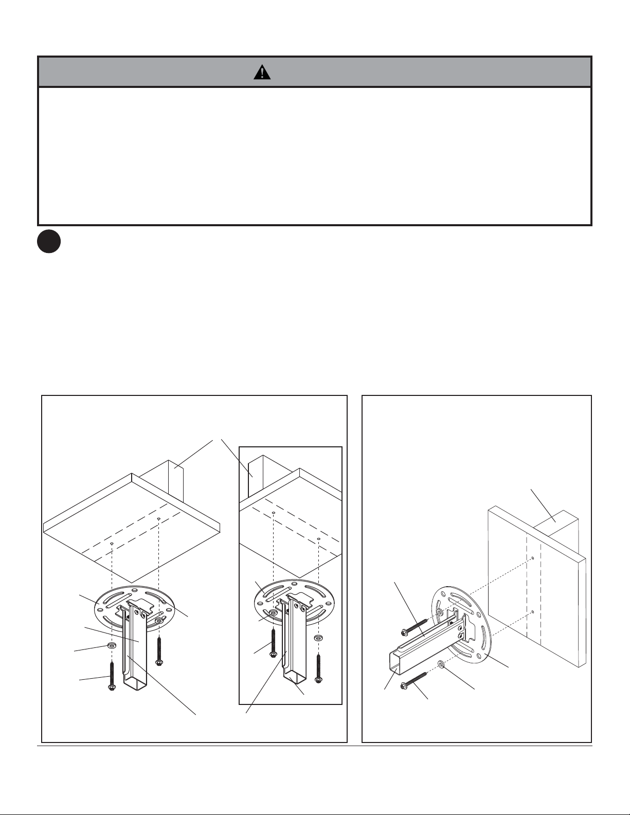
Installation to Wood Joist Ceilings or Wood Stud Walls
WARNING
• Installer must verify that the supporting surface will safely support the combined load of the equipment and all
attached hardware and components.
• Tighten wood screws so that ceiling/wall plate is fi rmly attached, but do not overtighten. Overtightening can damage
the screws, greatly reducing their holding power.
• Never tighten in excess of 80 in. • lb (9 N.M.).
• Make sure that mounting screws are anchored into the center of the stud or joist. The use of an "edge to edge" stud
fi nder is highly recommended.
• Hardware provided is for attachment of mount through standard thickness drywall or plaster into wood studs or
joists. Installers are responsible to provide hardware for other types of mounting situations (Not Evaluated by UL).
NOTE: Wall installation with models PRG-EXC, PRG-EXC-S and PRG-EXC-W is not available.
2
Use a stud fi nder to locate the edges of the stud or joist. Use of an edge-to-edge stud fi nder is highly
recommended. Based on its edges, draw a vertical line down the stud's or joist’s center. Place ceiling/wall plate
(AA) on wall or ceiling as a template, making sure that the two mounting slots are on the centerline.
For ceiling installation: Opening on outer channel (BB) indicates front of mount. Use the correct mounting slots
on the ceiling/wall plate depending on ceiling joist orientation as shown in fi gure 2.1 and fi gure 2.2. Mounting slots
on ceiling plate allow for 45° (±22.5) of rotation before securing to joist.
For wall installation: Opening on outer channel (BB) indicates top of mount.
Mark the center of the two mounting holes. Drill two 5/32" (4 mm) dia. holes 2-1/2" (65 mm) deep. Secure
ceiling/wall plate (AA) to wood stud or joist using two #14 x 2-1/2" wood screws (D) and two 1/4" washers (F)
as shown in fi gure 2.3.
Skip to step 3
CEILING INSTALLATION
WOOD
JOIST
WALL INSTALLATION
(EXCEPT FOR PRG-EXC MODELS)
fi g. 2.1
AA
BB
F
MOUNTING
SLOTS ALLOW
FOR ROTATION
BEFORE
SECURING TO
JOIST
D
OPENING ON OUTER CHANNEL (BB)
INDICATES FRONT OF MOUNT
Visit the Peerless Web Site at www.peerless-av.com
AA
F
D
fi g. 2.2
BB
6 of 14
fi g. 2.3
OPENING ON OUTER
CHANNEL (BB) INDICATES
TOP OF MOUNT
BB
D
ISSUED: 04-24-08 SHEET #: 055-9257-8 10-28-13
For customer care call 1-800-865-2112
WOOD
STUD
AA
F
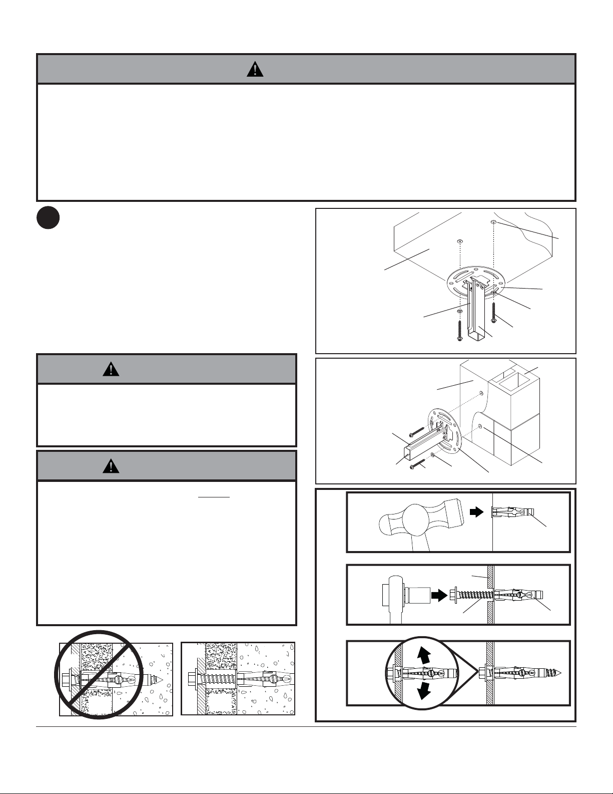
Installation to Concrete Ceilings or Concrete/Cinder Block Walls
WARNING
• When installing Peerless wall mounts on cinder block, verify that you have a minimum of 1-3/8" of actual concrete
thickness in the hole to be used for the concrete anchors. Do not drill into mortar joints! Be sure to mount in a solid
part of the block, generally 1" minimum from the side of the block. Cinder block must meet ASTM C-90 specifi ca-
tions. It is suggested that a standard electric drill on slow setting is used to drill the hole instead of a hammer drill to
avoid breaking out the back of the hole when entering a void or cavity.
• Concrete must be 2000 psi density minimum. Lighter density concrete may not hold concrete anchor.
• Installer must verify that the supporting surface will safely support the combined load of the equipment and all attached hardware and components.
NOTE: Wall installation with models PRG-EXC,
2
PRG-EXC-S and PRG-EXC-W is not available.
Place ceiling/wall plate (AA) on ceiling or wall as a
template. Note: Place ceiling/wall plate according
to position of opening in outer channel (BB) as
shown in fi gure 2.4. or fi gure 2.5. Drill two 5/16"
(8mm) dia. holes to a minimum depth of 2-1/2"
(64 mm). Attach ceiling/wall plate (AA) using two
concrete anchors (C), two #14 x 2-1/2" wood
screws (D) and two 1/4" washers (F) as shown in
fi gure 2.6. Tighten wood screws (D) until ceiling/
wall plate (AA) is fi rmly attached.
WARNING
• Tighten wood screws fi rmly, but do not overtighten.
Overtightening can damage the screws, greatly
reducing their holding power.
• Never tighten in excess of 80 in • lb (9 N.M.).
WARNING
• Always attach concrete anchors directly to loadbearing concrete.
• Never attach concrete anchors to concrete covered
with plaster, drywall, or other fi nishing material.
If mounting to concrete surfaces covered with a
fi nishing surface is unavoidable (not evaluated by
UL), the fi nishing surface must be counterbored
as shown below. Be sure concrete anchors do not
pull away from concrete when tightening screws. If
plaster/drywall is thicker than 5/8", custom fasteners
must be supplied by installer (not evaluated by UL).
AA
INCORRECT
concrete
AA
CORRECT
concrete
CEILING
INSTALLATION
fi g. 2.4
CONCRETE
CEILING
OPENING ON OUTER
CHANNEL (BB) INDICATES
FRONT OF MOUNT
BB
WALL INSTALLATION
(EXCEPT FOR EXC MODELS)
CONCRETE
BB
WALL
D
F
AA
fi g. 2.5
OPENING ON
OUTER CHANNEL
(BB) INDICATES
TOP OF MOUNT
fi g.
1
2.6
Drill holes and insert anchors (C).
2
AA
D
Place plate (AA) over anchors (C) and secure with screws (D).
3
C
AA
F
D
CINDER
BLOCK
WALL
C
concrete
surface
C
C
plaster/
dry wall
plaster/
dry wall
CUTAWAY VIEW
Visit the Peerless Web Site at www.peerless-av.com
7 of 14
Tighten all fasteners.
ISSUED: 04-24-08 SHEET #: 055-9257-8 10-28-13
For customer care call 1-800-865-2112
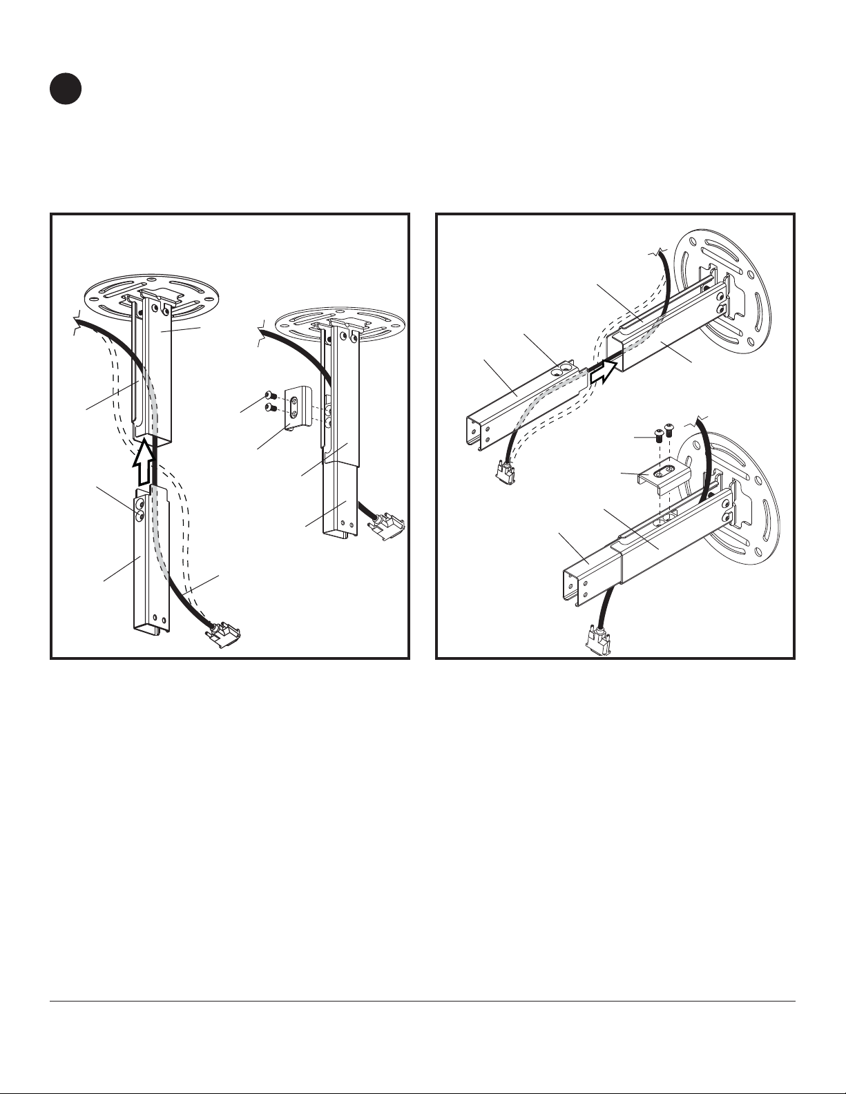
Installing Inner Channel and Routing Cables
Note: Be certain holes on inner channel (CC) face in the same direction of opening on outer channel (BB).
3
Note: Cables must be removed from projector before routing through channels. If cables are not removable from
projector, routing through channels is not an option.
Guide projector cables into openings in channels then insert inner channel (CC) into outer channel (BB) as shown
in fi gure 3.1 or 3.3.
Position inner channel (CC) to the desired extended position and secure using two M6 x 12 mm socket pin
screws (HH) through clamp plate (DD) and into inner channel (CC) as shown in fi gure 3.2 or 3.4.
CEILING INSTALLATION
fi g. 3.1
OPENING
HOLES
CC
BB
HH
DD
GUIDE
CABLES IN
CHANNELS
fi g. 3.2
BB
CC
WALL INSTALLATION
(EXCEPT FOR PRG-EXC MODELS)
OPENING
HOLES
CC
HH
DD
BB
CC
fi g. 3.3
BB
fi g. 3.4
Visit the Peerless Web Site at www.peerless-av.com
8 of 14
ISSUED: 04-24-08 SHEET #: 055-9257-8 10-28-13
For customer care call 1-800-865-2112
Installing Projector Mount
Installing PRG projector mount with ceiling installation: Attach vertical mounting plate (EE) to PRG projector
4
mount (A) using two M5 x 16 mm socket pin screws (GG), four 1/4" washers (F) and two locknuts (KK) as shown
in fi gure 4.1.
Installing PRG projector mount with wall installation: Position PRG projector mount (A) to the orientation
shown in fi gure 4.2 and attach to horizontal mounting plate (FF) using two M5 x 16 mm socket pin screws (GG),
four 1/4" washers (F) and two locknuts (KK).
NOTE:
mounting bracket (EE or FF) can make installation easier as shown in fi gure 4.3.
CEILING INSTALLATION
Placing washer (F) and nut (KK) combination on inside of PRG projector mount fi rst while attaching
fi g. 4.1
EE
A
GG
F
WALL INSTALLATION
(EXCEPT FOR PRG-EXC MODELS)
fi g. 4.2
FF
A
GG
F
ARROW
INDICATES
FRONT OF
MOUNT
F
ARROW
INDICATES
FRONT OF
MOUNT
KK
fi g. 4.3
PLACE WASHER (F) AND NUT
(KK) COMBINATION FIRST
KK
A
Ceiling installation: Insert vertical mounting plate (EE) into inner channel (CC) with PRG projector mount (A) in
5
the correct orientation shown in fi gure 5.1. Secure vertical mounting plate to inner channel using four M5 x 10 mm
socket pin screws (JJ) as shown in fi gure 5.2.
CEILING INSTALLATION
fi g. 5.1
fi g. 5.2
F
CC
F
KK
EE
A
ARROW
INDICATES
FRONT OF
MOUNT
Visit the Peerless Web Site at www.peerless-av.com
9 of 14
EE
CC
ISSUED: 04-24-08 SHEET #: 055-9257-8 10-28-13
For customer care call 1-800-865-2112
JJ

Wall installation: Insert horizontal mounting plate (FF) into inner channel (CC) as shown in fi gure 5.3. Secure
5
horizontal mounting plate to inner channel using four M5 x 10 mm socket pin screws (JJ) as shown in fi gure 5.4.
WALL INSTALLATION
(EXCEPT FOR PRG-EXC MODELS)
fi g. 5.3
ARROW INDICATES
FRONT OF MOUNT
CC
FF
A
Attaching Adapter Plate to Projector
NOTE: The projector you are installing may differ in appearance from the sample illustrated below.
6
Place projector upside down. Locate adapter plate (B) with notch facing forward as close to projector center of
gravity as possible without covering any mounting holes. Loosen channels with 4 mm security allen wrench (I),
and if there are only three mounting holes remove fourth channel. Using one channel for each mounting
hole, position feet of channels over mounting holes as shown below. Important: If projector does not have at least
three mounting holes, do not use this adapter plate.
NOTE: Some projectors have feet which can be removed and the corresponding threaded insert can be used for
a mounting hole.
NOTE: Once channels are in position retighten fasteners.
*Notch indicates front of projector.
fi g. 5.4
CC
JJ
FF
MOUNTING HOLE
*
Visit the Peerless Web Site at www.peerless-av.com
GENERIC PROJECTOR
10 of 14
FOOT OF CHANNEL
CHANNEL
B
ISSUED: 04-24-08 SHEET #: 055-9257-8 10-28-13
For customer care call 1-800-865-2112
Attach adapter plate (B) to projector using one screw (J, K, L or M) for each channel as shown below. Tighten
7
all screws, while keeping the center of gravity. Be sure that adapter plate (B) is straight. Adjust the feet of the
channels to keep the adapter plate level. Tighten all screws with 4 mm security allen wrench (I) while keeping the
center of gravity. If M3 x 8 mm screws (J) are used, tighten using 2 mm security allen wrench (H).
NOTE: Projectors will require different size screws for mounting. Use a combination of screws (J, K, L or M) and
foot adjustment that will result in channels of adapter plate (B) fi tting tightly against projector. Important: In order
to properly engage the threads in the mounting holes, the screw must be turned at least 3 full turns.
NOTE: If using screw (J), place washer (G) between screw (J) and foot of channel.
B
CAUTION
• It is the responsibility of the installer to ensure that
the projector is properly ventilated. Feet of channels
are used to raise the mount off the projector surface.
FOOT OF CHANNEL
WARNING
• Always use an assistant or mechanical lifting equipment to safely lift and position the projector.
J, K, L
or M
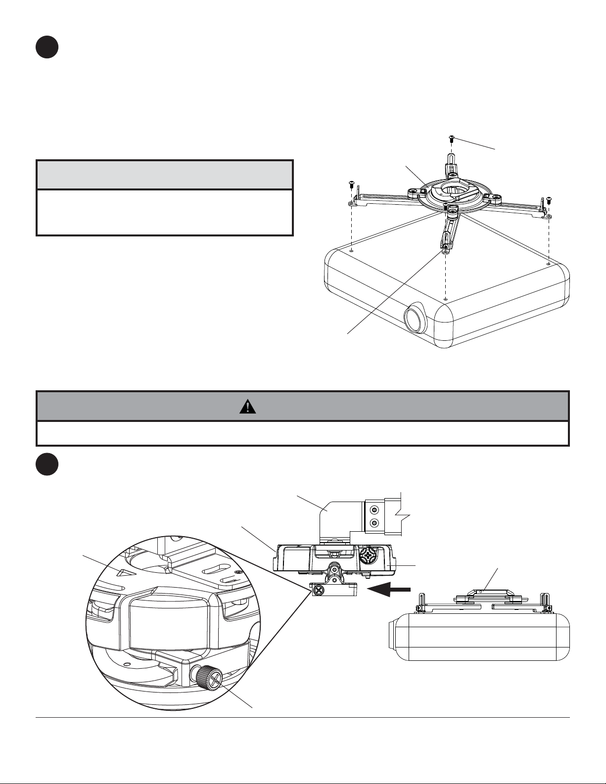
Slide connection block with projector into projector mount assembly (A) as shown. Push in and tighten captive
8
screw to secure projector to projector mount assembly (A).
FRONT OF MOUNT
ARROW
INDICATES
FRONT OF
MOUNT
Visit the Peerless Web Site at www.peerless-av.com
EE or FF
CAPTIVE SCREW
11 of 14
A
ISSUED: 04-24-08 SHEET #: 055-9257-8 10-28-13
For customer care call 1-800-865-2112
CONNECTION BLOCK

IMPORTANT: For security installations, insert one #10-32 x 1/4" socket pin screw (E) through projector mount
9
assembly (A) and into connection block as shown. Tighten screw with 4mm security allen wrench (I).
Projector Alignment
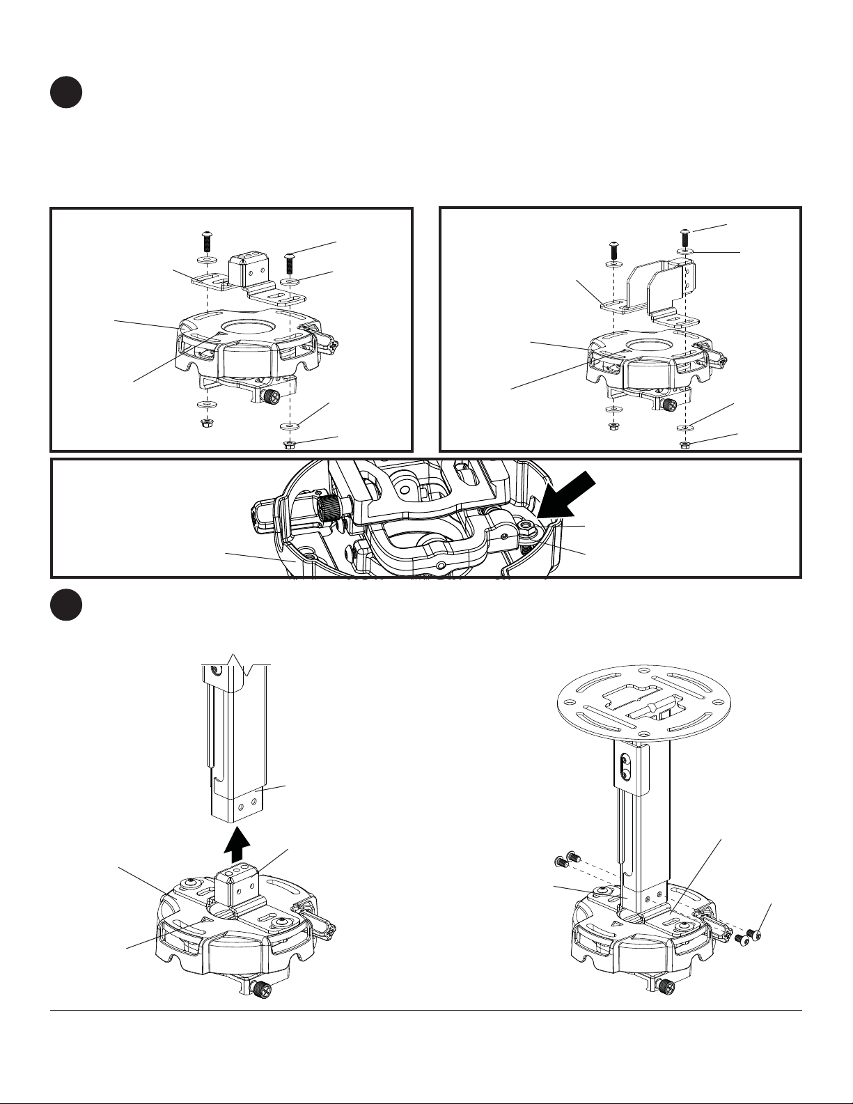
To adjust yaw (swivel): Loosen two screws indicated below half a turn using allen wrench (I). Align projector to
10
the desired swivel position and fully tighten screws indicated.
To adjust pitch (forward and backward tilt): Turn knob on back of mount as shown below. Pull knob out and
turn by hand for easy adjustment or insert #2 phillips screwdriver in end of knob and turn.
To adjust roll (side to side tilt): Turn knob on side of mount as shown below. Pull knob out and turn by hand for
easy adjustment or insert #2 phillips screwdriver in end of knob and turn.
ARROW INDICATES
FRONT OF MOUNT
CONNECTION BLOCK
A
E
KNOB FOR PITCH
ADJUSTMENT
KNOB FOR ROLL
ADJUSTMENT
MOUNT ASSEMBL Y
NOT SHOWN FOR
CLARITY
20° (±10°) SWIVEL
SWIVEL ADJUSTMENT
TOP VIEW
BACK OF MOUNT
SCREWS FOR
SWIVEL ADJUSTMENT
WARNING
• Do not loosen adjustment screws to the point they become disengaged from the mount. Weight of the projector
should be supported in case of accidental disengagement.
NOTE: For tamper proofi ng of projector alignment, see step 10-1 on page 13.
12 of 14
Visit the Peerless Web Site at www.peerless-av.com
ISSUED: 04-24-08 SHEET #: 055-9257-8 10-28-13
For customer care call 1-800-865-2112

10-1
To prevent tampering with the pitch and roll adjustments: Tighten the two tamper resistant security screws
on the projector mount assembly using 4 mm security allen wrench (I) to lock the pitch and roll adjustments as
shown below.
Note: Tighten screws fi rmly, but do not overtighten. Overtightening can damage the mount.
CAUTION
• Do not adjust pitch or roll while tamper resistant security screws are fully engaged.
• Loosen the two tamper resistant security screws one complete turn before adjusting the projector mount assembly
or damage may occur.
TO LOCK ROLL,
TIGHTEN
TAMPER RESISTANT
SECURITY SCREW
TO LOCK PITCH,
TIGHTEN TAMPER
RESISTANT
SECURITY SCREW
FRONT VIEW
SIDE VIEW
Adjusting Mount Extension
11
While supporting the weight of the projector, loosen clamp plate screws half a turn and position projector to the
desired extended position. Retighten clamp plate screws securely.
WARNING
• On ceiling installations, clamp plate adjustment screws support weight of projector when fully tightened. Weight of
the projector will need to be supported if clamp plate screws are loosened.
CEILING INSTALLATION
CLAMP PLATE
SCREWS
Visit the Peerless Web Site at www.peerless-av.com
DD
13 of 14
WALL INSTALLATION
(EXCEPT FOR EXC MODELS)
ISSUED: 04-24-08 SHEET #: 055-9257-8 10-28-13
CLAMP PLATE
SCREWS
DD
For customer care call 1-800-865-2112

Install Cable Covers
12
Cut cable covers (LL) to the length of inner channel (CC) and outer channel (BB) openings, leaving space for
cables if routed through channels. Snap cable covers (LL) into openings as shown.
CEILING INSTALLATION
LL
CUT TO
LENGTH OF
OPENING
BB
CC
LL
CUT TO
LENGTH OF
OPENING
CABLES
WALL INSTALLATION
(EXCEPT FOR EXC MODELS)
CC
LL
CUT TO
LENGTH OF
OPENING
BB
LL
CUT TO
LENGTH OF
OPENING
Visit the Peerless Web Site at www.peerless-av.com
14 of 14
All other brand and product names are trademarks or registered trademarks of their respective owners.
ISSUED: 04-24-08 SHEET #: 055-9257-8 10-28-13
For customer care call 1-800-865-2112
© 2013, Peerless Industries, Inc. All rights reserved.
 Loading...