

Page 1
™
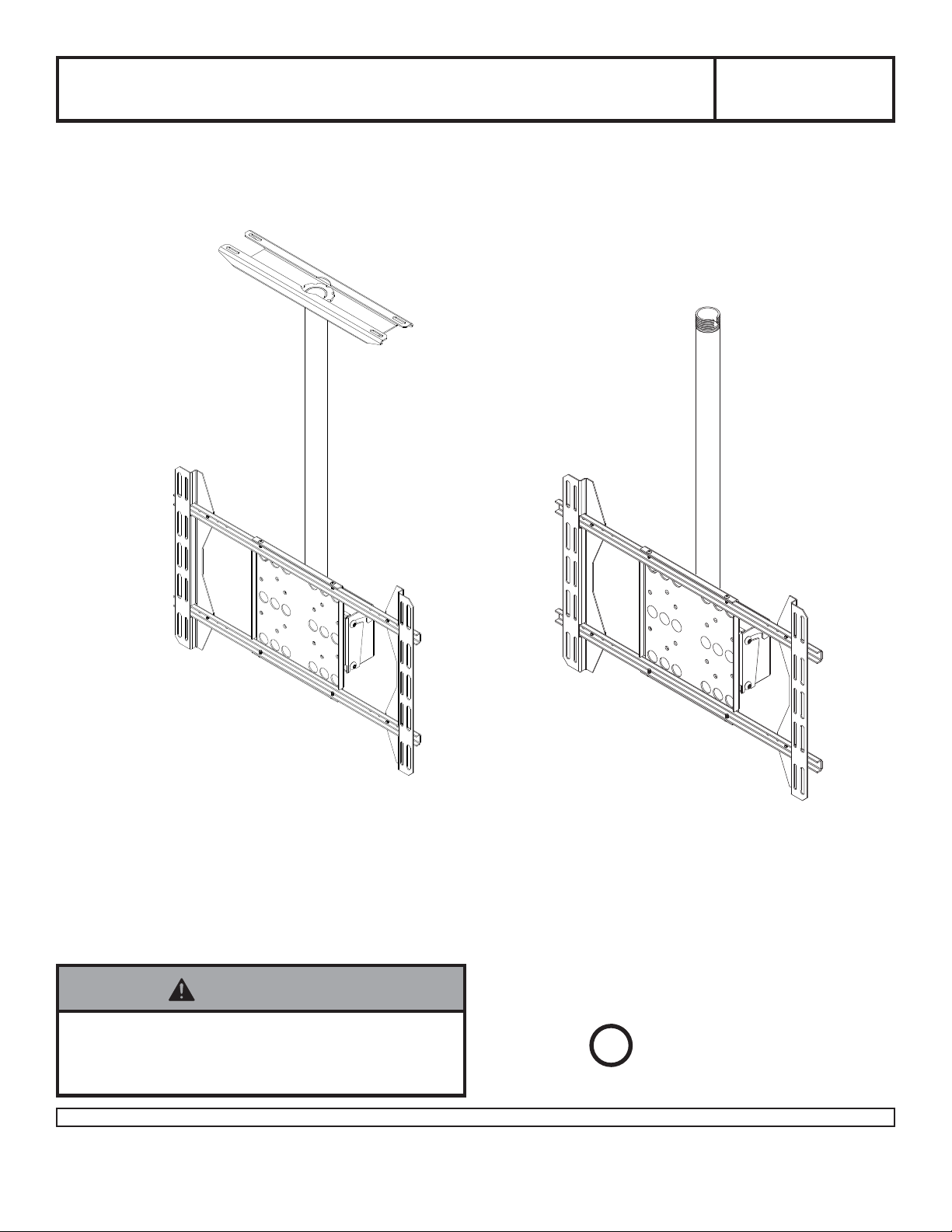
Solid•Point
Flat Panel Straight
Installation and Assembly -
Column Mount
Read instruction sheet before you start installation and assembly.
Model:PLCM-UN1,
PLCM-UN1-CP
PLCM-UN1PLCM-UN1-CP
Note: Installation for 32"-50" LCD and Flat Panel Screens
WARNING
• Installer must verify that the ceiling will safely support
the combined weight of all attached equipment and
hardware.
1 of 9
Visit the Peerless Web Site at www.peerlessmounts.com For customer care call 1-800-729-0307 or 708-865-8870.
U
L
©
Max Load Capacity: 125 lbs (56.7 kg)
This product is intended for use with UL Listed
products and must be installed by a qualified
professional installer.
USC
ISSUED:09-07-07 SHEET #: 202-9199-2 01-13-09
Page 2
WARNING
• Do not begin to install your Peerless product until you have read and understood the instructions and warnings
contained in this Installation Sheet. If you have any questions regarding any of the instructions or warnings, please
call Peerless customer care at 1-800-729-0307.
• This product should only be installed by someone of good mechanical aptitude, and fully understands
these instructions.
• Never exceed the Maximum UL Load Capacity .
• Always use an assistant or mechanical lifting equipment to safely lift and position equipment.
• Tighten screws firmly , but do not overtighten. Overtightening can damage the items, greatly reducing their holding
power.
• Installer must verify that the ceiling will safely support the combined weight of all attached equipment and hardware.
Table of Contents
Parts List..............................................................................................................................................................................3
Installing Ceiling Plate (model PLCM-UN1-CP only)..............................................................................................................4
Installing Flat Panel Straight Column Mount to ceiling .......................................................................................................... 5
Installing Adapter Plate .........................................................................................................................................................6
Installing Adapter Plate to Screen.....................................................................................................................................7, 8
Installation of Screen to Flat Panel Straight Column Mount ..................................................................................................9
2 of 9
Visit the Peerless Web Site at www.peerlessmounts.com For customer care call 1-800-729-0307 or 708-865-8870.
ISSUED:09-07-07 SHEET #: 202-9199-2 01-13-09
Page 3
y
A
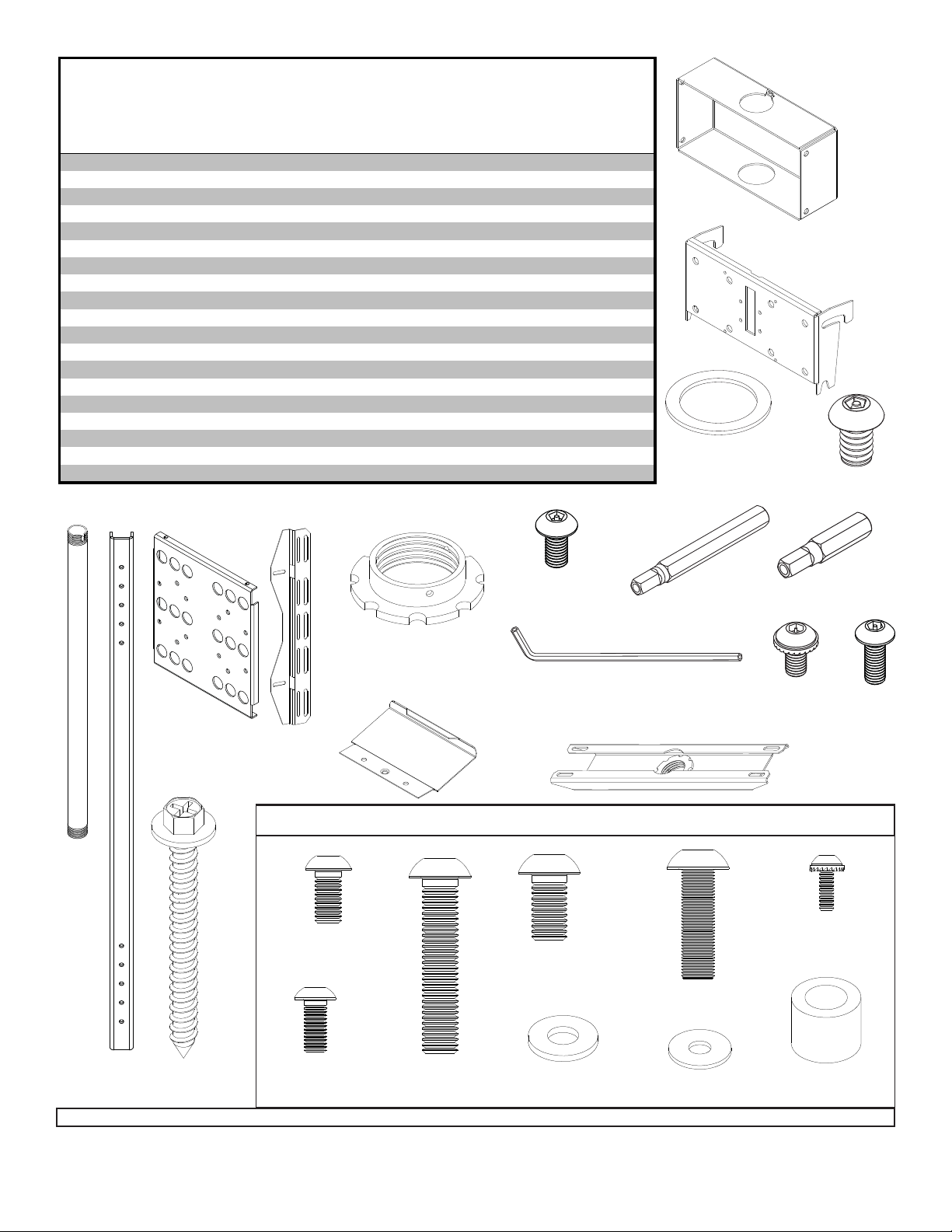
Before you begin, make sure all parts shown are included with your product.
PARTS LIST
PLCM-UN1 PLCM-UN1-CP
Description Qt
ceiling arm box 1 201-1062 201-1062
tilt bracket 1 200-1552 200-1552
B
33" support pipe 1 139-1088 139-1088
C
c-channel 2 200-1331 200-1331
D
adapter plate 1 201-1651 201-1651
E
vertical brackets 2 200-1302 200-1302
F
retaining collar 1 1800-375 1800-375
G
M5 x 10 mm penta-pin screw 4 505-9010 505-9010
H
2.875 OD x 2.125 ID x .062 H fiber washer 1 540-9432 540-9432
I
M10 x 15 mm penta-pin screw 8 520-9263 520-9263
J
M10 x 2" penta-pin tool 1 520-9260 520-9260
K
M5 x 1" penta-pin tool 1 520-9249 520-9249
L
4 mm security allen wrench 1 560-9646 560-9646
N
O #10-32 x 3/8" socket pin screw 4 520-1151 520-1151
P 10-32 x 1/2" socket pin screw 4 520-1055 520-1055
Q ceiling bracket 1 - 128-1039
R ceiling bracket end cap 2 - 2PT-22CA01D
S #14 wood screws 4 - 5S1-015-C03
T M5 x 10 mm penta-pin screw (not shown) 1 - 505-9010
NOTE: Parts may appear slightly different than illustrated
Part # Part #
A
B
I
J
C
E
G
F
M6 x 12 mm (6)
520-1050
H
N
R
Q
Adapter Bracket Fasteners
M8 x 15 mm (6)
520-1068
M8 x 25 mm (4)
520-1 101
K
L
O
M4 x 10 mm(8)
520-1 156
P
D
Visit the Peerless Web Site at www.peerlessmounts.com For customer care call 1-800-729-0307 or 708-865-8870.
S
M5 x 12 mm (8)
520-1064
M8 x 40 mm (4)
520-1 152
3 of 9
1/4" washer (6)
540-9440
#10 washer (8)
540-9400
ISSUED:09-07-07 SHEET #: 202-9199-2 01-13-09
1/2" spacer (4)
540-1015
Page 4

Skip to page 5 for PLCM-UN-1
For Wood Joist Finished Ceiling, Exposed
1
Wood Joists, or Wood Beam Ceiling. Drill four
5/32" (4 mm) dia. holes to a minimum depth of 2.5"
(64 mm) INTO JOIST CENTERS. Attach ceiling
plate (Q) with four #14 x 2.5" (6 mm x 65 mm) wood
screws (S) using a 3/8" (10 mm) socket wrench.
Tighten wood screws (S) so ceiling plate is firmly
attached. Snap end caps (R) into place.
Q
WARNING
• Tighten wood screws so that ceiling plate is firmly
attached, but do not overtighten. Overtightening can
damage screws, greatly reducing their holding power.
• Never tighten in excess of 80 in • lb (9 N.M.).
• Make sure that mounting screws are anchored into the
center of the joists. The use of an "edge to edge" stud
finder is highly recommended.
1
For Concrete Ceilings drill four 5/16" (8 mm) dia.
holes to a minimum depth of 1 3/4" (45 mm).
Attach ceiling plate (Q) using concrete expansion
anchors as shown in 1-1 and 1-2. Then snap end
caps (R) into place.
Align hole in ceiling plate with hole in ceiling.
1-1
Gently hammer in concrete anchor.
Use a 10 mm wrench to tighten concrete anchor to
1-2
80 in • lb (9 N.M.) maximum torque to expand
anchors.
S
R
Q
ACC 210
R
FOR PRODUCT SAFETY USE ONL Y RA WL
#5005 OR HIL TI™ HL814 CONCRETE ANCHORS.
Order accessory kit #ACC 210 which contains four
.312 x 1.625
(8 mm x 41 mm) concrete expansion anchors.
WARNING
• Always attach concrete expansion anchors directly to
load-bearing concrete.
• Never attach concrete expansion anchors to concrete
covered with plaster, drywall, or other finishing material.
Visit the Peerless Web Site at www.peerlessmounts.com For customer care call 1-800-729-0307 or 708-865-8870.
™
1-1
4 of 9
1-2
PLASTER/
DRYWALL
CONCRETE
ISSUED:09-07-07 SHEET #: 202-9199-2 01-13-09
Page 5

Installing Flat Panel Straight Column Mount to ceiling
Thread support pipe (C) into threaded fitting in ceiling plate (UL Listed CMJ470, included with PLCM-UN1-CP).
2
Tighten - four or five complete turns - leaving slot aligned with one small hole in the side of the ceiling plate threaded
fitting. Insert and tighten one M5 x 10 mm penta-pin screw (T) provided with ceiling plate as shown. Use the M5
penta-pin tool (L) to tighten screw. BY HAND, insert four M10 x 15 mm penta-pin screws (J) into threaded holes in
the sides of ceiling arm box (A). Leave approximately 1/4" of exposed thread. Slide ceiling arm box (A) and fiber
washer (I) onto end of support pipe (C). Thread retaining collar (G) onto threaded end of support pipe (C). Tighten four or five complete turns. Slide ceiling arm box (A) down so that it is on top of retaining collar (G). Insert and
tighten one M5 x 10 mm penta-pin screw (H) into retaining collar (G) as shown. Insert one M5 x 10 mm penta-pin
screw (H) through the tab on the back of ceiling arm box (A). Use M5 penta-pin tool (L) to tighten screw just enough
to stabilize support pipe (C).
NOTE: UL Listed ADJ or EXT extension columns series can be used in combination with, or in place of
support pipe (C) to achieve different lengths.
ceiling plate (Q) included with
PLCM-UN1-CP only
G
C
T
C
H
BACK OF CEILING
A
ARM BOX
J
J
I
G
1/4"
H
5 of 9
Visit the Peerless Web Site at www.peerlessmounts.com For customer care call 1-800-729-0307 or 708-865-8870.
ISSUED:09-07-07 SHEET #: 202-9199-2 01-13-09
Page 6

Attach c-channels (D) to adapter plate (E) using four 10-32 x 1/2" socket pin screws (P).
3
P
E
D
Installing Adapter Plate
T o assemble the adapter bracket (E) to your flat screen product, please refer to the compatibility chart and configurations
table on accompanying screen compatibility chart. First, locate your flat screen product in the compatibility chart using the
manufacturers name and model number. Next, note the configuration letter shown in the far right hand column. Finally, use
the configurations table, which appears after the compatibility chart, to determine the correct mounting hardware for your
flat screen product.
Slide vertical brackets (F) onto c-channels (D) as shown below. Refer to the table on the last p age of the screen
4
compatibility chart to determine the proper assembly of the vertical bracket (F). For standard bracket mounting, see
figure 4.1. For reverse bracket mounting, see figure 4.2.
Example: For a Toshiba model 50 HP82 50" screen, assemble the vertical bracket (F) as shown in figure 4.2 below
(reverse bracket mounting).
F
D
E
fig. 4.1
Bracket Mounting: Standard
F
D
E
fig. 4.2
Bracket Mounting: Reverse
6 of 9
Visit the Peerless Web Site at www.peerlessmounts.com For customer care call 1-800-729-0307 or 708-865-8870.
ISSUED:09-07-07 SHEET #: 202-9199-2 01-13-09
Page 7

Attach tilt bracket (B) to adapter bracket (E) using four M10 x 15 mm penta-pin screws (J) as shown below .
5
E
E
B
B
J
J
LANDSCAPE
Installing Adapter Plate to Screen
Set a cloth on the floor to prevent scratching the screen. Place the screen on the floor face down. If the screen has
6
knobs on the back, remove them. Place adapter bracket (E) on the center of the screen. Slide the vertical brackets (F)
along the c-channels (D) of the adapter bracket (E) until the slots on the back of the vertical brackets (F) are aligned to
the holes on the back of the screen. Fasten vertical brackets (F) to c-channels (D) using four 10-32 x 3/8" socket pin
serrated washer head screws (O).
NOTE: Do not fully tighten the screws (O) to allow the adapter bracket to slide along the vertical brackets (F) freely .
PORTRAIT
F
D
O
F
E
7 of 9
Visit the Peerless Web Site at www.peerlessmounts.com For customer care call 1-800-729-0307 or 708-865-8870.
ISSUED:09-07-07 SHEET #: 202-9199-2 01-13-09
Page 8

Installation of Screen to Flat Panel Straight Column Mount
Slide the vertical brackets (F) along the c-channels (D) of the adapter bracket (E) until the slots on the back of the
7
vertical brackets (F) are aligned to the holes on the back of screen. Fully tighten the four 10-32 x 3/8" socket pin
serrated washer head screws (O) which hold the vertical brackets (F) to the c-channels (D). Refer to the
accompanying screen compatibility chart to determine the proper fasteners to use. Attach the assembled adapter
bracket to the back of the screen using screws, upper and lower spacers as pictured. V erify that all holes are
properly aligned, then use the security allen wrench (N) to tighten the screws.
NOTE: See figure 7 below for slot sizes.
Example: For a Toshiba model 50 HP82 50" screen, attach the vertical brackets (F) to the screen using eight
M4 x 10 mm serrated socket pin screws or M5 x 12 mm socket pin screws through the small slots on the vertical
brackets (F). Please refer to the corresponding configuration note for more details. Upper spacers are required for
this configuration.
fig. 7
Mounting Slots
SMALL SLOTS ARE USED
FOR M4 AND M5 SCREWS.
O
F
D
E
SCREWS
UPPER SPACERS
LOWER SPACERS
LARGE SLOTS ARE USED
FOR M6 AND M8 SCREWS.
MOUNTING SLOTS:
LARGE
8 of 9
Visit the Peerless Web Site at www.peerlessmounts.com For customer care call 1-800-729-0307 or 708-865-8870.
MOUNTING SLOTS:
SMALL
ISSUED:09-07-07 SHEET #: 202-9199-2 01-13-09
Page 9

Attach tilt bracket (B) to ceiling arm box (A) by sliding the tilt bracket (B) over four M10 x 15 mm socket pin serrated
8
washer head screws (J) as shown below. Set desired tilt and tighten all fasteners.
NOTE: Wall not shown for clarity .
B
A
J
9 of 9
Visit the Peerless Web Site at www.peerlessmounts.com For customer care call 1-800-729-0307 or 708-865-8870.
©2009 Peerless Industries, Inc. All rights reserved.
Peerless is a registered trademark of Peerless Industries, Inc.
Solid•Point is a trademark of Peerless Industries, Inc.
All other brand and product names are trademarks or registered trademarks of their respective owners.
ISSUED:09-07-07 SHEET #: 202-9199-2 01-13-09
 Loading...