

Page 1
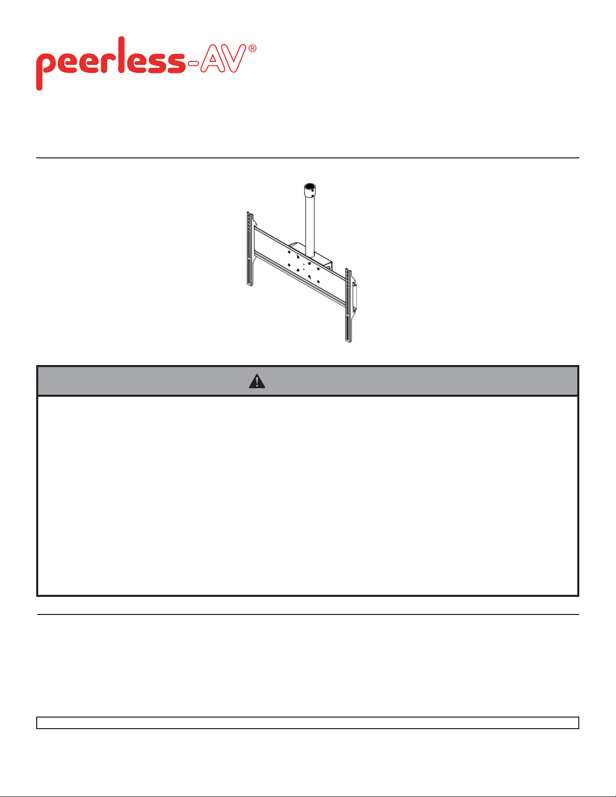
Installation and Assembly: Flat Panel Conversion Kit For
up to 50" LCD and Plasma Screens
Models: PLCK-UNL, PLCK-1
Read instruction sheet before you start installation and assembly.
Maximum Load Capacity: 125 lb (57 kg)
WARNING
• Do not begin to install your Peerless product until you have read and understood the instructions and warnings
contained in this Installation Sheet. If you have any questions regarding any of the instructions or warnings, for US
customers please call Peerless customer care at 1-800-865-2112, for all international customers, please contact
your local distributor.
• This product should only be installed by someone of good mechanical aptitude, has experience with basic building
construction, and fully understands these instructions.
• Make sure that the supporting surface will safely support the combined load of the equipment and all attached
hardware and components.
• Never exceed the Maximum Load Capacity.
• Always use an assistant or mechanical lifting equipment to safely lift and position equipment.
• Tighten screws fi rmly, but do not overtighten. Overtightening can damage the items, greatly reducing their holding
power.
• This product is intended for indoor use only. Use of this product outdoors could lead to product failure and personal
injury.
Table of Contents
Parts List.................................................................................................................................................................................2
Attaching Extension Column To Ceiling Plate Or Existing Extension Column ........................................................................3
Attaching Ceiling Arm Box to Extension Column ....................................................................................................................4
PLCK-1 Installation .................................................................................................................................................................5
PLCK-UNL Installation ........................................................................................................................................................ 6-8
1 of 9
Visit the Peerless Web Site at www.peerless-av.com For customer care call 708-865-2112.
ISSUED:02-22-07 SHEET #: 202-9197-5 (2013-10-01)
Page 2
A
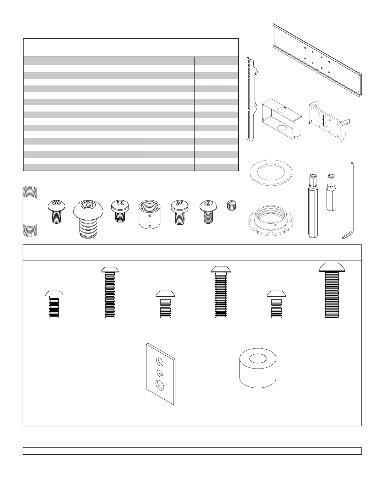
Before you begin, make sure all parts shown are included with your product.
Parts may appear slightly different than illustrated.
Parts List
Description Qty Part # Qty Part #
adapter plate 1 201-1109 -
AA
deep bracket 2
BB
ceiling arm box 1 201-1062 1 201-1062
tilt bracket 1 200-1552 1 200-1552
B
18" extension column connector 1 128-1095 1 128-1095
C
retaining collar 1 1800-375 1 1800-375
D
M5 x .8 x 10 mm penta-pin™ screw 4 505-9010 4 505-9010
E
fiber washer 1 540-9432 1 540-9432
F
M10 x 1.5 x 15 mm penta-pin screw 8 520-9263 8 520-9263
G
M10 x 2" penta-pin tool 1 520-9260 1 520-9260
H
M5 x 1" penta-pin tool 1 520-9249 1 520-9249
I
M5 x .8 x 8 mm phillips Type F screw 4 520-1167 4 520-1167
J
extension column connector
K
M5 x .8 x 10 mm phillips screw
L
M5 x .8 x 10 mm socket pin screw
M
4 mm security allen wrench
N
#10-32 x 3/16" slotted set screw
O
PLCK-UNL PLCK-1
201-1510
1 580-1010 1 580-1010
2 520-9250 2 520-9250
2 520-1063 2 520-1063
1 560-9646 1 560-9646
2 520-1187 2 520-1187
-
C
BB
F
A
AA
H
B
N
I
Security Adapter Bracket Fasteners for PLCK-UNL
M5 x 12 mm (4)
520-1064
GE
M5 x 25 mm (4)
520-1122
J M OK
L
M6 x 12 mm (4)
520-1050
M6 x 25 mm (4)
520-1211
D
M8 x 12 mm (4)
520-1724
M8 x 25 mm (4)
520-1101
spacer (4)
540-1059
multi-washer (4)
580-1398
2 of 9
Visit the Peerless Web Site at www.peerless-av.com For customer care call 708-865-2112.
ISSUED:02-22-07 SHEET #: 202-9197-5 (2013-10-01)
Page 3
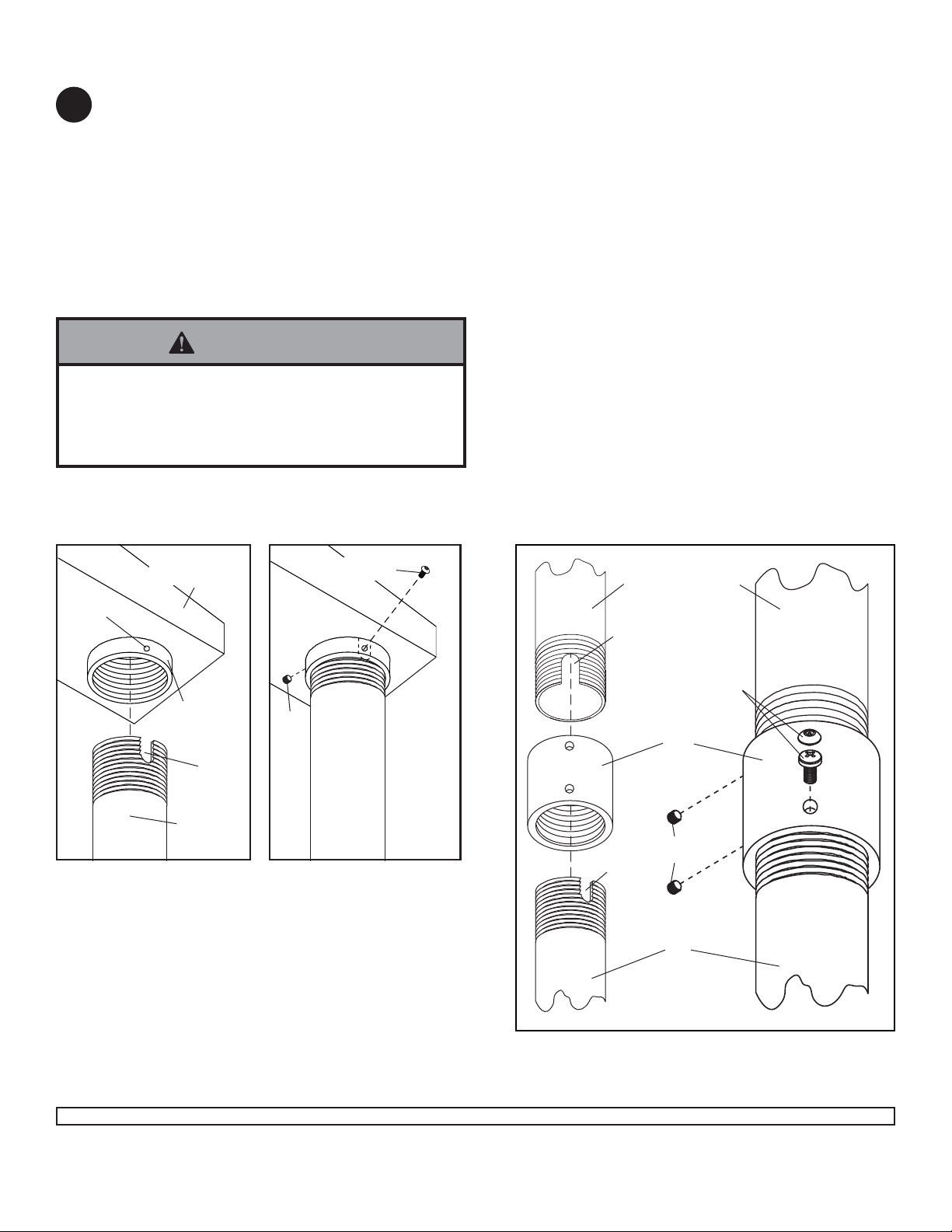
Attaching Extension Column To Ceiling Plate Or Existing Extension Column
Attach extension column (C) to column connector (K) or ceiling plate (not supplied). Align slot in the extension
1
column with one of the small holes in extension column connector (K) or existing retaining collar (not supplied).
Insert and tighten one phillips screw (L) through connector (K) or existing retaining collar into slot on the extension
column.
Note: For security option, use security screw (M) in place of screw (L). Tighten security screw (M) using 4 mm
security allen wrench (N)
Repeat step one to attach column connector (K) to existing extension column (not supplied).
Note: To prevent columns from unwinding when mount is swiveled, both screws (L) or (M) must be inserted.
Note: Slotted set screws (O) are used to jam against the threads of each connecting joint to prevent any excess
movement. Do not overtighten screws; overtightening screws will damage threads making it diffi cult to separate the
products.
WARNING
• For TV mounts: If equipment weighs over 50 lb, and
the extension exceeds 12’, a Stress Decoupler (models DCT 100/DCS 200) must be used in combination
with EXT extension columns.
Small
Hole
Attaching to Ceiling Plate
Ceiling plate
(not supplied)
retaining
collar
Slot
L or M
O
C
Attaching to Existing Extension Column
extension column
(not supplied)
slot
L or M
K
slot
O
C
3 of 9
Visit the Peerless Web Site at www.peerless-av.com For customer care call 708-865-2112.
ISSUED:02-22-07 SHEET #: 202-9197-5 (2013-10-01)
Page 4

Attaching Ceiling Arm Box to Extension Column
Insert four M10 x 15 mm penta-pin screws (G) into threaded holes on the sides of ceiling arm box (A) as shown in
2
fi gure 2.1. Leave approximately 1/4" of exposed thread as shown in detail 1. Tighten screws using M10 penta-pin
tool (H).
Slide ceiling arm box (A) onto end of extension column (C) followed by extension column fi ber washer (F) and
retaining collar (D) as shown in fi gure 2.2. Tighten retaining collar and align slot of extension column (A) with hole
of retaining collar (D).
G
1/4"
A
fi g. 2.1
DETAIL 1
Slot
C
fi g. 2.2
Small hole
Insert and tighten one M5 x 10 mm penta-pin screw (E) through the hole of the retaining collar (D) and slot of exten-
3
sion column (A) as shown in fi gure 3.1.
Insert one M5 x 10 mm penta-pin screw (E) through the tab on the back of ceiling arm box (A) as shown in rear
view.
Use the M5 penta-pin tool (I) to tighten screws.
F
D
E
E
Visit the Peerless Web Site at www.peerless-av.com For customer care call 708-865-2112.
fi g. 3.1
4 of 9
Rear View
ISSUED:02-22-07 SHEET #: 202-9197-5 (2013-10-01)
Page 5

Attaching Tilt Bracket to Plasma Or LCD Screen For PLCK-1
Note: Skip to page 6 for PLCK-UNL installation.
4
Note: Refer to adapter plate instruction sheet (sold separately) for attachment of adapter plate to plasma or LCD
screen before proceeding with step 4. Note: Screen and adapter plate may appear different than illustrated.
LCD SCREEN
Attach tilt bracket (B) to adapter plate using four M5 x 8 mm phillips screws (J) as shown in fi gure 4.1.
LCD SCREEN
ADAPTER PLATE
B
J
fi g. 4.1
PLASMA SCREEN
Attach tilt bracket (B) to adapter plate using four M10 x 15 mm penta-pin screws (G) as shown in fi gure 4.2 and 4.3.
Tighten using M10 penta-pin tool (H).
LANDSCAPE
PLASMA SCREEN
ADAPTER PLATE
B
G
PORTRAIT
(NOT to be used
with UNL models)
fi g. 4.2
Hang The Tilt Bracket on the Ceiling Arm Box For PLCK-1
Hang tilt bracket (B) onto ceiling arm box (A). Adjust
5
tilt as desired and tighten four M10 x 1.5 x 15 mm
penta-pin screws (G) securely using M10 penta-pin
tool (H).
B
PLASMA SCREEN
ADAPTER PLATE
B
G
fi g. 4.3
A
WARNING
• For a safe assembly be sure to fully tighten four
screws (G).
5 of 9
Visit the Peerless Web Site at www.peerless-av.com For customer care call 708-865-2112.
ISSUED:02-22-07 SHEET #: 202-9197-5 (2013-10-01)
G
Page 6

Installing Adapter Brackets for PLCK-UNL
WARNING
• Tighten screws so adapter brackets are fi rmly attached. Do not tighten with excessive force. Overtightening can
cause stress damage to screws, greatly reducing their holding power and possibly causing screw heads to become
detached. Tighten to 40 in. • lb (4.5 N.M.) maximum torque.
• If screws don't get three complete turns in the screen inserts or if screws bottom out and bracket is still not tightly
secured, damage may occur to screen or product may fail.
To prevent scratching the screen, set a cloth on a fl at, level surface that will support the weight of the screen. Place
4
screen face side down. If screen has knobs on the back, remove them to allow the adapter brackets to be attached.
Place adapter brackets (BB) on back of screen, align to holes, and center on back of screen as shown below.
Attach the adapter brackets to the back of the screen using the appropriate combination of screws, multi-washers
and spacers as shown in step 4-1 or 4-2.
NOTE: Top and bottom holes on screen must always be used.
NOTE: Tighten using 4 mm allen wrench (N).
X
BB
Note: "X" dimensions should be equal.
Notes:
• The number of fasteners used will vary,
depending upon the type of screen.
• Multi-washers and spacers may not be
used, depending upon the type of screen.
• Use the corresponding hole in the multi-
washer that matches your screw size.
CENTER BRACKETS
VERTICALLY ON BACK OF
SCREEN
X
MULTI-WASHER
MEDIUM HOLE FOR M5 SCREWS
SMALL HOLE FOR M4 SCREWS
LARGE HOLE FOR M6 SCREWS
NOTE: For fl at back screens proceed to step 4-1. For bump-out or recessed back screen skip to step 4-2
6 of 9
Visit the Peerless Web Site at www.peerless-av.com For customer care call 708-865-2112.
ISSUED:02-22-07 SHEET #: 202-9197-5 (2013-10-01)
Page 7

For Flat Back Screen
Begin with the shortest length screw, hand thread through multi-washer and adapter bracket into screen as
4-1
shown below. Screw must make at least three full turns into the mounting hole and fi t snug into place. Do not
over tighten. If screw cannot make three full turns into the screen, select a longer length screw from the baffl ed
fastener pack. Repeat for remaining mounting holes, level brackets and tighten screws.
NOTE: Spacers may not be used, depending upon the type of screen.
If you have any questions, please call Peerless customer care at 1-800-865-2112.
SCREEN
MULTI-WASHER
SCREW
ADAPTER BRACKET (BB)
For Bump-out or Recessed Back Screen
Begin with longer length screw, hand thread through multi-washer, adapter bracket and spacer in that order into
4-2
screen as shown below. Screw must make at least three full turns into the mounting hole and fi t snug into place.
Do not over tighten. If screw cannot make three full turns into the screen, select a longer length screw from the
baffl ed fastener pack. Repeat for remaining mounting holes, level brackets and tighten screws.
SCREEN
SPACER
If you have any questions, please call Peerless customer care at 1-800-865-2112.
MULTI-WASHER
SCREW
ADAPTER BRACKET (BB)
7 of 9
Visit the Peerless Web Site at www.peerless-av.com For customer care call 708-865-2112.
ISSUED:02-22-07 SHEET #: 202-9197-5 (2013-10-01)
Page 8

Attaching Tilt Bracket to Adapter Plate for PLCK-UNL
Attach tilt bracket (B) to adapter plate (AA) using four
5
M10 x 15 mm penta-pin screws (G) as shown below.
Tighten screws using M10 penta-pin tool (H).
Hang tilt bracket (B) onto ceiling arm box (A). Adjust
6
tilt as desired and tighten four M10 x 15 mm pentapin screws (G) securely using M10 penta-pin tool (H).
AA
• For a safe assembly be sure to fully tighten four
M10 x 15 mm penta-pin screws (G).
WARNING
G
B
B
Mounting and Removing Flat Panel Screen for PLCK-UNL
WARNING
• Always use an assistant or mechanical lifting equipment to safely lift and position the plasma television.
A
G
Hook deep brackets (BB) onto adapter plate (AA),
7
then slowly swing screen in as shown. Turn screws
clockwise at least six times to prevent screen from
being removed as shown in detail 2. Tighten using 4
mm allen wrench (N).
NOTE: It is important to lock screen down! To
lock the screen down, tighten screws to deep bracket
(BB) as shown in detail 2.
To remove screen from mount, loosen screws, swing
screen away from mount, and lift screen off of mount.
AA
AA
SCREWS
BB
BB
DETAIL 2
8 of 9
Visit the Peerless Web Site at www.peerless-av.com For customer care call 708-865-2112.
All other brand and product names are trademarks or registered trademarks of their respective owners.
ISSUED:02-22-07 SHEET #: 202-9197-5 (2013-10-01)
© 2013, Peerless Industries, Inc. All rights reserved.
Peerless Industries, Inc.
2300 White Oak Circle
Aurora, Il. 60502
www.peerless-av.com
Page 9

LIMITED FIVE-YEAR WARRANTY
Peerless Industries, Inc. (“Peerless”) warrants to original end-users of Peerless® products will be free from defects in material and workmanship, under normal
use, for a period of fi ve years from the date of purchase by the original end-user (but in no case longer than six years after the date of the product’s manufacture).
In no event shall the duration of any implied warranty of merchantability or fi tness for a particular purpose be longer than the period of the applicable
express warranty set forth above. Some states do not allow limitations on how long an implied warranty lasts, so the above limitation may not apply to you.
This warranty does not cover damage caused by (a) service or repairs by the customer or a person who is not authorized for such service or repairs by Peerless,
(b) the failure to utilize proper packing when returning the product, (c) incorrect installation or the failure to follow Peerless’ instructions or warnings when installing,
In no event shall Peerless be liable for incidental or consequential damages or damages arising from the theft of any product, whether or not secured
by a security device which may be included with the Peerless® product. Some states do not allow the exclusion or limitation of incidental or consequential
This warranty is in lieu of all other warranties, expressed or implied, and is the sole remedy with respect to product defects. No dealer, distributor, installer or other
person is authorized to modify or extend this Limited Warranty or impose any obligation on Peerless in connection with the sale of any Peerless® product.
At its option, Peerless will repair or replace, or refund the purchase price of, any product which fails to conform with this warranty.
using or storing the product, or (d) misuse or accident, in transit or otherwise, including in cases of third party actions and force majeure.
damages, so the above limitation or exclusion may not apply to you.
This warranty gives specifi c legal rights, and you may also have other rights which vary from state to state.
Patented. Utiltiy Patent No. 8,517,322.
www.peerless-av.com
© 2013 Peerless Industries, Inc.
9 of 9
Visit the Peerless Web Site at www.peerless-av.com For customer care call 708-865-2112.
ISSUED:02-22-07 SHEET #: 202-9197-5 (2013-10-01)
 Loading...