

Page 1
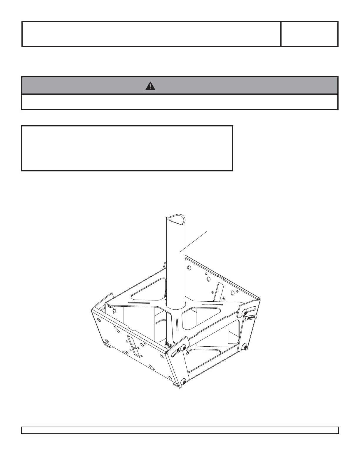
Installation and Assembly - Solid•Point™ Plasma Ceiling Mount
Model: PLB 1
Read instruction sheet before you start
installation and assembly.
WARNING
• Failure to install M5 penta-pin screw (D) can cause the mount to fall!
Applications
Installation of PLP adapter plate................................. Step 3
Installation of LC adapter plate ................................... Step 4
Maximum Load Capacity:
300 lb (136 kg)
EXTENSION COLUMN
(SOLD SEP ARA TEL Y)
Not compatible with
AEC0609, EXT002 and
EXT006 models
Visit the Peerless Web Site at www.peerlessindustries.com
1 1
55
1 of
5 ISSUED: 04-22-03 SHEET #: 201-9046-5 04-20-10
1 1
55
For customer service call 1-800-729-0307 or 708-865-8870.
Page 2
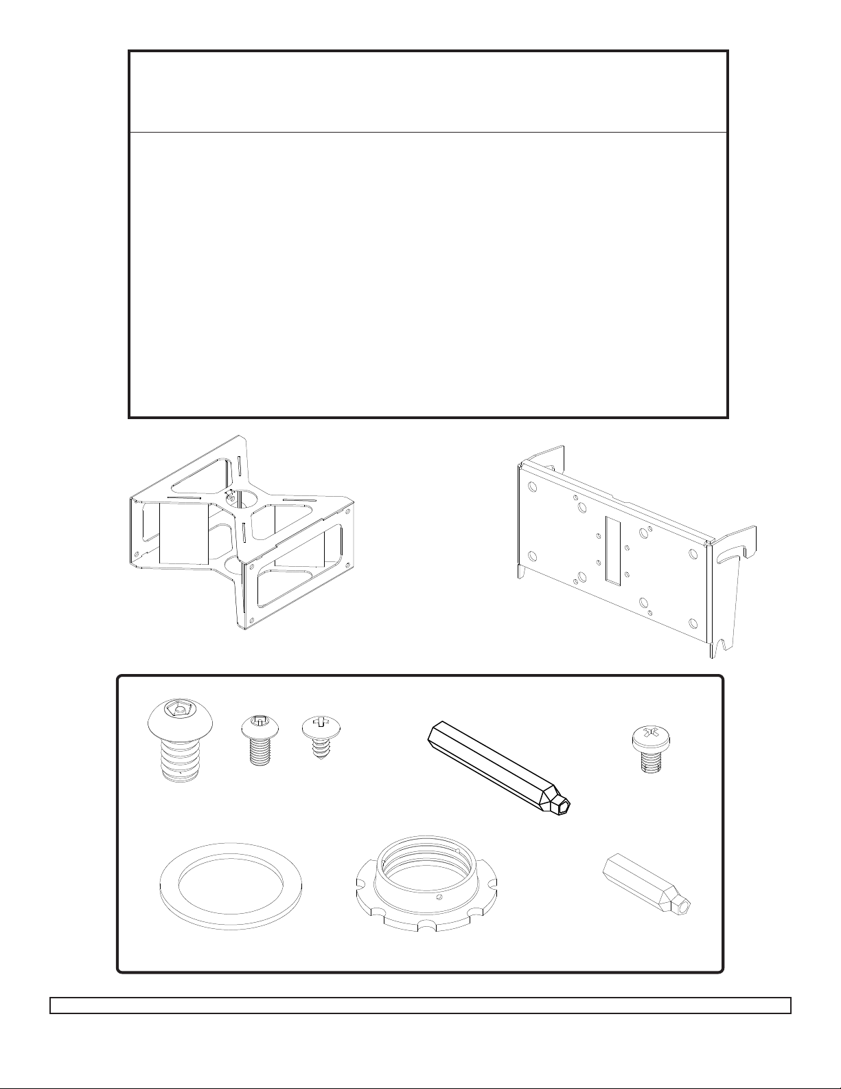
Before you start check the parts list to insure all of the parts shown are included.
Parts List
Description Qty. Part Number
A interface bracket 1 200-1090
B tilt bracket 2 200-1552
C M10 x 1.5 x 15 mm penta-pin™ screw 16 520-9263
D M5 x .8 x 10 mm self-tapping penta-pin screw 1 505-9010
E #8 x 3/8" truss head sheet metal screw 1 520-1078
F M10 x 2" penta-pin tool 1 520-9260
G M5 x 1" penta-pin tool 1 520-9249
H 2.125" ID x 2.875" OD x .062" H fiber washer 1 540-9432
I retaining collar 1 1800-375
J M5 x .8 x 8 mm phillips screw 8 520-1167
Note: Some parts may appear slightly different than illustrated.
C
A
H
D
E
B
J
F
I
G
Fasteners
Visit the Peerless Web Site at www.peerlessindustries.com
2 2
55
2 of
5 ISSUED: 04-22-03 SHEET #: 201-9046-5 04-20-10
2 2
55
For customer service call 1-800-729-0307 or 708-865-8870.
Page 3

Note: Hole with notch indicates bottom of interface bracket as shown in detail 1.
Insert interface bracket (A) onto extension column (sold separately) and attach using fiber
washer (H) and retaining collar (I) as shown (right).
IMPORTANT: Retaining collar (I) requires a M5 x 10 mm penta-pin screw (D). Carefully
thread retaining collar (I) onto end of extension column. Tighten ret aining collar (I) at least
four complete turns ending with one of the small holes aligned with slot in the end of extension column. Insert and tighten M5 x 10 mm penta-pin screw (D) using M5 x 1" penta-pin
tool (G) where shown in Illustration A.
WARNING
• M5 penta-pin screw (D) is self tapping and may be
hard to get started but is essential to this installation.
Failure to install this screw can cause the mount to
fall!
EXTENSION
COLUMN
SLOT
A
A
EXTENSION
COLUMN (SOLD
SEPARATELY)
Not compatible
with AEC0609,
EXT002 and
EXT006 models
D
Detail 1
H
I
A
Illustration A
Screw eight M10 x 15 mm penta-pin screws (C) into holes of interface bracket (A) leaving approximately 1/4" of
exposed thread as shown below and in detail 2.
I
C
1
/4"
A
Detail 2
A
Visit the Peerless Web Site at www.peerlessindustries.com
C
3 3
55
3 of
5 ISSUED: 04-22-03 SHEET #: 201-9046-5 04-20-10
3 3
55
For customer service call 1-800-729-0307 or 708-865-8870.
Page 4

NOTE: Refer to adapter plate instruction sheet for attachment of adapter
plate to screen before proceeding with step 3. If your adapter plate has an
aluminum race attached to it, remove before proceeding and discard race. It is
not used with this product.
Installation of PLP Adapter Plates
Attach tilt bracket (B) to each adapter plate using four M10
x 15 mm penta-pin screws (C). T ighten M10 x 15 mm
penta-pin screws (C) using M10 x 2" penta-pin tool (F).
Skip to step 5.
ADAPTER
PLATE
Note: Screen and adapter
plate may appear different
than illustrated.
NOTE: Refer to adapter plate instruction sheet for attachment of adapter
plate to screen before proceeding with step 4. If your adapter plate has an
aluminum race attached to it, remove before proceeding and discard race. It is
not used with this product.
Installation of LC Adapter Plates
Attach tilt bracket (B) to adapter bracket using four M5 x 8 mm phillips screws (J).
Note: Do not use M5 x 6 mm screws that are included with the adapter bracket.
C
B
Note: Screen and adapter
plate may appear different
than illustrated.
Visit the Peerless Web Site at www.peerlessindustries.com
SCREEN
ADAPTER
BRACKET
B
J
4 4
55
4 of
5 ISSUED: 04-22-03 SHEET #: 201-9046-5 04-20-10
4 4
55
For customer service call 1-800-729-0307 or 708-865-8870.
Page 5

Hang each plasma screen on interface bracket (A) as shown in Illustration B. Adjust tilt as desired for each
screen and tighten eight M10 x 15 mm penta-pin screws (C) on interface bracket (A) using M10 x 2" penta-pin
tool (F).
After both screens are installed, lock interface bracket (A) into
place using one #8 x 3/8" truss head sheet metal screw (E) as
shown in Illustration C and detail 3.
Note: Make sure both screens are installed properly before
locking interface bracket (A) into place.
E
Detail 3
C
Illustration B
A
Illustration C
Visit the Peerless Web Site at www.peerlessindustries.com
© 2007, Peerless Industries, Inc. All rights reserved.
All other brand and product names are trademarks or registered trademarks of their respective owners.
5 5
55
5 of
5 ISSUED: 04-22-03 SHEET #: 201-9046-5 04-20-10
5 5
55
For customer service call 1-800-729-0307 or 708-865-8870.
 Loading...