

Installation and Assembly:
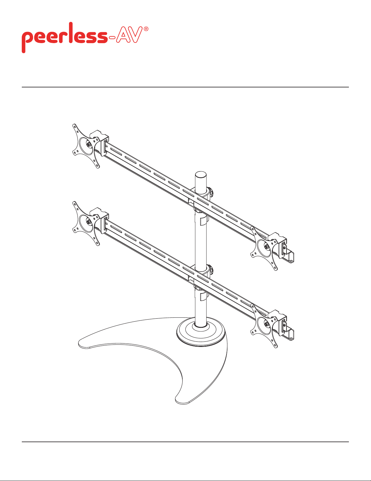
Quad Monitor Stand for up to 24" Monitors
Models: LCZ-4F430B
Max Load Capacity per display: 19.8 lb (9 kg)
2300 White Oak Circle • Aurora, Il 60502 • (800) 865-2112 • Fax: (800) 359-6500 • www.peerless-av.com
ISSUED: 04-05-11 SHEET #: 090-9200-5 (2013-12-03)

NOTE: Read entire instruction sheet before you start installation and assembly.
WARNING
• Do not begin to install your Peerless product until you have read and understood the instructions and warnings
contained in this Installation Sheet. If you have any questions regarding any of the instructions or warnings, please
call Peerless customer care at 1-800-865-2112.
• This product should only be installed by someone of good mechanical aptitude, has experience with basic building
construction, and fully understands these instructions.
• Make sure that the supporting surface will safely support the combined load of the equipment and all attached
hardware and components.
• Never exceed the Maximum Load Capacity. See page one.
• Always use an assistant or mechanical lifting equipment to safely lift and position equipment.
• Tighten screws fi rmly, but do not overtighten. Overtightening can damage the items, greatly reducing their holding
power.
• Be sure to use designated fasteners and tools to assemble product. If correct fasteners and tools are not used,
product may fail.
Table of Contents
Parts List.................................................................................................................................................................................3
Installation of Base .................................................................................................................................................................4
Attaching Mounting Plates to Display .....................................................................................................................................6
2 of 23
ISSUED: 04-05-11 SHEET #: 090-9200-5 (2013-12-03)

Before you begin, make sure all parts shown are included with your product.
y
Parts List
Description
A base 1
B mounting bracket 4
C pole 1
D lock collar 2
E crossbar
F M4 x 12mm screw
G M4 x 30mm screw
H spacer 16
I
knob
J cable clip
K 3mm allen wrench
L 4mm allen wrench
Parts may appear slightly different than illustrated.
Qt
2
16
16
4
2
1
1
CD FG
A
B
H
E
KL MJI
3 of 23
ISSUED: 04-05-11 SHEET #: 090-9200-5 (2013-12-03)

Installation of Base
Hand tighten pole (C) onto base (A) as shown in fi gure 1.1. Tighten set screw to secure pole using 3mm allen
1
wrench (K) as shown in rear view.
C
SET SCREW
REAR VIEW
Feed cables through base cover (M). Insert base
2 3
cover onto pole (C).
M
C
fi g 1.1
Insert lock collar (D) onto pole (C).
Adjust to desired height and tighten by hand.
D
C
4 of 23
ISSUED: 04-05-11 SHEET #: 090-9200-5 (2013-12-03)
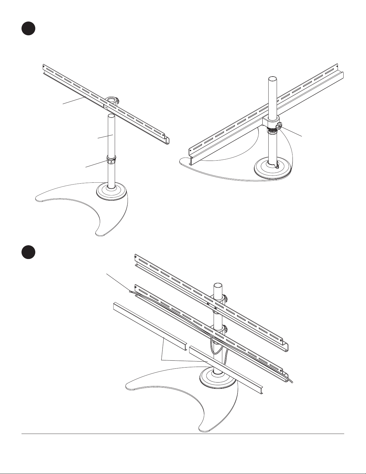
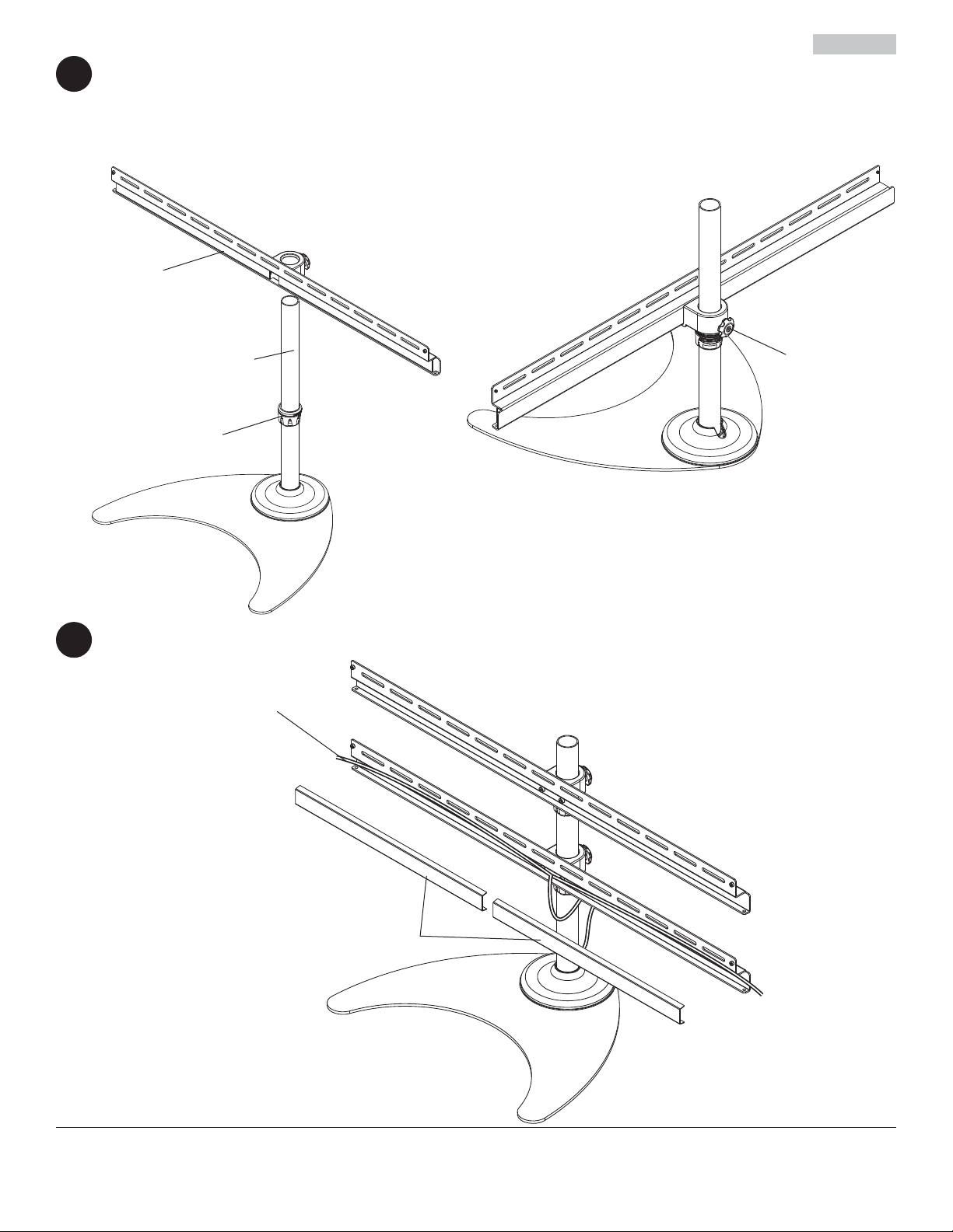
Insert crossbar (E) onto pole (C) and let it rest on lock collar (D) as shown in fi gure 4.1.
4
Adjust rotation of crossbar and hand tighten knob as shown in fi gure 4.2.
Repeat steps 3 and 4 for second lock collar (D) and crossbar (E).
fi g 4.1
E
fi g 4.2
C
D
Cables may be routed through crossbar by removing crossbar covers.
5
CABLES
KNOB
CROSSBAR COVERS
5 of 23
ISSUED: 04-05-11 SHEET #: 090-9200-5 (2013-12-03)

Attaching Mounting Plates to Display
WARNING
• Tighten screws so mounting plates are fi rmly attached. Do not tighten with excessive force. Overtightening can
cause stress damage to screws, greatly reducing their holding power and possibly causing screw heads to become
detached. Tighten to 40 in. • lb (4.5 N.M.) maximum torque.
• If screws don't get three complete turns in the screen inserts or if screws bottom out and bracket is still not tightly
secured, damage may occur to screen or product may fail.
To prevent scratching the screen, set a cloth on a fl at, level surface that will support the weight of the display. Place
6
display face side down. If display has knobs on the back, remove them to allow the mounting plates to be attached.
Place mounting plates (B) on back of display.
Choose hole pattern as shown in detail 1.
FOR DISPLAYS WITH FLAT BACKS: Hand tighten mounting plates (B) to display using four 12mm screws (F) as
shown in fi gure 6.1. Leave 1/64" space between screws (F) and mounting plates (B).
FOR DISPLAYS WITH RECESSED BACKS: Hand tighten mounting plates (B) to display using four 30mm screws
(G) and four spacers (H) as shown in fi gure 6.2. Leave 1/64" space between screws (G) and mounting plates (B).
1/64"
(.4mm)
B
VESA 100mm
VESA 75mm
DETAIL 1
VESA 75mm
VESA 100mm
fi g 6.1
1/64"
(.4mm)
fi g 6.2
F
B
G
H
6 of 23
ISSUED: 04-05-11 SHEET #: 090-9200-5 (2013-12-03)

Remove knobs (I) from rear of mounting brackets (B) as shown in detail 2. Hook mounting brackets (B) onto crossbar (E)
as shown in fi gure 6.3.
Adjust position of displays horizontally to desired location and install knobs (I) into rear of mounting brackets. Displays
need to be the same distance from center of crossbar (E) to ensure weight is evenly distributed. Knobs (I) may be
tightened using 3mm allen wrench (K).
B
I
DETAIL 2
B
E
fi g 6.3
Once displays are aligned, tighten screws (F,G) as shown in fi gure 6.5.
Cables may be routed using cable clip (J) as shown in fi gure 6.6.
I
fi g 6.4
I
J
CABLES
fi g 6.5 fi g 6.6
7 of 23
ISSUED: 04-05-11 SHEET #: 090-9200-5 (2013-12-03)

Instalación y ensamblaje:
•Estante para cuatro monitores para monitores de hasta 24"
Modelo: LCZ-4F430B
Capacidad máxima de soportar carga
por pantalla: 19.8 lb (9kg)
2300 White Oak Circle • Aurora, Il 60502 • (800) 865-2112 • Fax: (800) 359-6500 • www.peerless-av.com
PUBLICADO: 04-05-11 HOJA #: 090-9200-5 (2013-12-03)

Español
Nota:
Lea la hoja de instrucciones completa antes de comenzar la instalación y el ensamblaje.
ADVERTENCIA
• No comience a instalar su producto de Peerless hasta haber leído y entendido las instrucciones y las advertencias
contenidas en la Hoja de Instalación. Si tiene alguna pregunta acerca de cualquiera de las instrucciones o las advertencias, por favor, llame a Servicio al Cliente de Peerless al 1-800-865-2112 si está en EE. UU. Si es un cliente
internacional, por favor, comuníquese con su distribuidor local.
• Este producto sólo debe ser instalado por una persona que tenga una buena aptitud mecánica, que tenga experiencia en construcción básica de edifi cios y que entienda estas instrucciones en su totalidad.
• Asegúrese de que la superfi cie de apoyo sostendrá, con seguridad, la carga combinada del equipo y todos los
fi jadores y componentes.
• Nunca sobrepase la capacidad máxima de soportar carga aceptada.
• Siempre cuente con la ayuda de un asistente o utilice un equipo mecánico de izar para levantar y colocar el equipo
con más seguridad.
• Apriete los tornillos con fi rmeza, pero no en exceso. Apretarlos en exceso puede dañar los artículos y puede dis-
minuir signifi cativamente su fuerza de fi jación.
• Asegúrese de utilizar los sujetadores y las herramientas indicados para armar el producto. Si no utiliza los sujetadores y las herramientas indicados, el producto podría fallar.
Tabla de contenido
Vea la página 8.
Lista de piezas..................................................................................................................................................................... 10
Instalación de la base ...........................................................................................................................................................11
Fijación de las placas de montaje en la pantalla ................................................................................................................. 13
9 de 23
PUBLICADO: 04-05-11 HOJA #: 090-9200-5 (2013-12-03)

Antes de comenzar, asegúrese de que su producto contiene todas las piezas que se muestran.
Lista de piezas
Español
Descripción
A base 1
B soporte de montaje 4
C poste 1
D collar de fijación 2
E barra transversal
F tornillos de M4 x 12mm
G tornillos de M4 x 30mm
H espaciadores 16
I
perillas
J clip para cables
K llave allen de 3mm
L llave allen de 4mm
Las piezas pueden verse un poco distintas a la ilustración.
Cant.
2
16
16
4
2
1
1
CD FG
A
B
H
E
KL MJI
10 de 23
PUBLICADO: 04-05-11 HOJA #: 090-9200-5 (2013-12-03)

Instalación de la base
Apriete el poste (C), con la mano, en la base (A), como se muestra en la fi gura 1.1. Apriete el tornillo de sujeción
1
para fi jar el poste utilizando una llave allen de 3mm (K), como se muestra en la vista trasera.
C
Español
TORNILLO DE SUJECIÓN
VISTA TRASERA
Pase los cables por la cubierta de la base (M).
2 3
Inserte la cubierta de la base en el poste (C).
M
C
fi g 1.1
Inserte el collar de fi jación (D) en el poste (C).
Ajuste a la altura deseada y apriete con la mano.
D
C
11 de 23
PUBLICADO: 04-05-11 HOJA #: 090-9200-5 (2013-12-03)

Inserte la barra transversal (E) en el poste (C) y deje que descanse sobre el collar de fi jación (D), como se muestra
4
en la fi gura 4.1.
Ajuste la rotación de la barra transversal y apriete la perilla con la mano, como se muestra en la fi gura 4.2.
Repita los pasos 3 y 4 para instalar un segundo collar de fi jación (D) y una segunda barra transversal (E).
fi g 4.2
fi g 4.1
E
Español
C
D
Los cables se pueden acomodar por la barra transversal quitando las cubiertas de la barra transversal.
5
CABLES
MANO
CUBIERTAS DE LA
BARRA TRANSVERSAL
12 de 23
PUBLICADO: 04-05-11 HOJA #: 090-9200-5 (2013-12-03)

Español
Fijación de las placas de montaje en la pantalla
ADVERTENCIA
• Apriete los tornillos de manera que los soportes adaptadores se fi jen con fi rmeza. No los apriete con fuerza
excesiva. Apretar los tornillos en exceso puede causarles daño por forzarlos y puede disminuir signifi cativamente
su fuerza de fi jación y podría causar el desprendimiento de las cabezas de los tornillos. Apriete los tornillos a un
máximo de 40 pulg-lb (4.5 N•m) de par torsor.
• Si no se les da tres vueltas completas a los tornillos en los insertos de la pantalla o si los tornillos topan fondo y el
soporte todavía no está fi rme, se podría dañar la pantalla o el producto podría no funcionar bien.
Para no rayar la pantalla, coloque un trapo sobre una superfi cie plana y nivelada que sostenga el peso de la
6
pantalla. Coloque la pantalla boca abajo. Si la pantalla tiene perillas en la parte trasera, quíteselas para poder fi jar
las placas de montaje.Coloque las placas de montaje (B) en la parte trasera de la pantalla.
Escoja una confi guración de agujeros, como se muestra en el detalle 1.
SI LA PANTALLA TIENE LA PARTE TRASERA PLANA: Apriete
las placas de montaje (B) con la mano en la pantalla utilizando
cuatro tornillos de 12 mm (F), como se muestra en la fi gura 6.1.
Deje un espacio de 1/64" entre los tornillos (F) y las placas de
montaje (B).
SI LA PANTALLA TIENE LA PARTE TRASERA EMPOTRADA:
Apriete las placas de montaje (B) con la mano en la pantalla
utilizando cuatro tornillos de 30mm (G) y cuatro espaciadores (H),
como se muestra en la fi gura 6.2. Deje un espacio de 1/64" entre
los tornillos (G) y las placas de montaje (B).
1/64"
(.4mm)
B
VESA 100mm
VESA 75mm
DETALLE 1
VESA 75mm
VESA 100mm
1/64"
(.4mm)
fi g 6.2
F
fi g 6.1
B
G
H
13 de 23
PUBLICADO: 04-05-11 HOJA #: 090-9200-5 (2013-12-03)

Español
Quite las perillas (I) de la parte trasera de los soportes de montaje (B), como se muestra en el detalle 2. Enganche los
soportes de montaje (B) en la barra transversal (E).
Ajuste la posición horizontal de las pantallas como desee e instale las perillas (I) en la parte trasera de los soportes de
montaje. Las pantallas deben estar a la misma distancia del centro de la barra transversal (E) para asegurarse de que el
peso se distribuya uniformemente. Las perillas (I) se pueden apretar utilizando una llave allen de 3mm (K).
B
I
DETALLE 2
B
E
fi g 6.3
I
Cuando haya alineado las pantallas, apriete los tornillos (F,G), como se muestra en la fi gura 6.5.
Los cables se pueden acomodar utilizando el clip para cables (J), como se muestra en la fi gura 6.6.
I
fi g 6.4
J
CABLES
fi g 6.5 fi g 6.6
14 de 23
PUBLICADO: 04-05-11 HOJA #: 090-9200-5 (2013-12-03)

Installation et montage:
Estante con ojete para cuatro monitores para monitores de
hasta 24".
Modele: LCZ-4F430B
Capacité de charge maximale établie
par affi chage: 19.8 lb (9kg)
2300 White Oak Circle • Aurora, Il 60502 • (800) 865-2112 • Fax: (800) 359-6500 • www.peerless-av.com
PUBLIÉ LE : 04-05-11 FEUILLE no : 090-9200-5 (2013-12-03)

Français
Remarque : lisez entièrement la fi che d’instructions avant de commencer l’installation et l’assemblage.
AVERTISSEMENT
• Ne commencez pas à installer votre produit Peerless avant d’avoir lu et assimilé les instructions et les
avertissements contenus dans cette fi che d’installation. Pour toute question concernant les instructions ou
les avertissements, veuillez appeler le service à la clientèle de Peerless au 1-800-865-2112; tous les clients
internationaux sont priés de contacter leur distributeur local.
• Ce produit doit être installé uniquement par quelqu’un possédant une bonne aptitude à la mécanique, une
expérience de la construction immobilière et ayant bien compris ces instructions.
• Assurez-vous que la surface de support puisse soutenir sans danger la charge totale de l’équipement ainsi que des
pièces et composants qui y sont attachés.
• Ne dépassez jamais la capacité de charge maximum établie. Reportez-vous à la page 15.
• Pour lever et positionner l’équipement en toute sécurité, faites-vous toujours aider par une autre personne ou
utilisez un dispositif de levage mécanique.
• Serrez fermement les vis, mais sans excès. Un serrage excessif peut endommager les composants et en réduire
considérablement la capacité de support.
• Assurez-vous d’utiliser les fi xations et outils désignés pour l’assemblage du produit. L’utilisation de fi xations et
d’outils inappropriés peut causer une défaillance du produit.
Table des matières
Liste des pièces ................................................................................................................................................................... 17
Montage de la base ............................................................................................................................................................. 18
Fixation des plaques de montage à l’écran ......................................................................................................................... 20
16 sur 23
PUBLIÉ LE : 04-05-11 FEUILLE no : 090-9200-5 (2013-12-03)

Avant de commencer, assurez-vous que toutes les pièces indiquées sont incluses avec le produit.
Liste des pièces
Français
Description
A base 1
B support de fixation 4
C Montant 1
D Collier d’arrêt 2
E Traverse
F vis de M4 x 12mm
G vis de M4 x 30mm
H entretoises 16
I
boutons
J serre-câble
K clé hexagonale de 3mm
L clé hexagonale de 4mm
Il est possible que les pièces semblent légèrement différentes de l’illustration.
Qté
2
16
16
4
2
1
1
CD FG
A
B
H
E
KL MJI
17 sur 23
PUBLIÉ LE : 04-05-11 FEUILLE no : 090-9200-5 (2013-12-03)

Montage de la base
Vissez à la main le montant (C) sur la base (A) comme illustré à la fi gure 1.1. Serrez la vis de calage pour fi xer le
1
montant à l’aide d’une clé hexagonale de 3mm (K) comme illustré dans la vue arrière.
C
Français
VIS DE CALAGE
VUE ARRIÈRE
Faites passer les câbles dans le couvercle de la
2 3
base (M). Insérez le couvercle de la base dans le
montant (C).
M
C
fi g 1.1
Insérez le collier d’arrêt (D) dans le montant (C).
Réglez-le à la hauteur souhaitée et serrez à la main.
D
C
18 sur 23
PUBLIÉ LE : 04-05-11 FEUILLE no : 090-9200-5 (2013-12-03)
Insérez la traverse (E) dans le montant (C) et laissez-la reposer sur le collier d’arrêt (D)
4
comme illustré à la fi gure 4.1.
Réglez la rotation de la traverse et serrez le bouton à la main comme illustré à la fi gure 4.2.
Répétez les étapes 3 et 4 pour installer un collier de blocage seconde (D) et une seconde barre transversale (E).
fi g 4.2
fi g 4.1
E
Français
C
D
Les câbles peuvent être acheminés dans la traverse en retirant ses couvercles.
5
CÂBLE
BOUTON
COUVERCLES DE LA TRAVERSE
19 sur 23
PUBLIÉ LE : 04-05-11 FEUILLE no : 090-9200-5 (2013-12-03)

Français
Fixation des plaques de montage à l’écran
AVERTISSEMENT
• Serrez les vis de manière à fi xer solidement les supports adaptateurs. N’employez pas une force excessive pour ce
faire. Un serrage excessif peut causer des contraintes risquant d’endommager les vis, de réduire considérablement
leur pouvoir de maintien et d’en détacher les têtes. Serrez les vis à un couple maximum de 4,5 Nm (40 po-lb).
• Si les vis ne sont pas enfoncées de trois tours complets dans les inserts ou si elles sont serrées au maximum sans
parvenir à maintenir solidement le support, l’écran peut être abîmé ou le produit détérioré.
Afi n d’éviter de rayer l’écran, posez un morceau de tissu sur une surface plane et de niveau qui peut supporter le
6
poids de l’écran. Posez l’écran à plat, tourné vers le bas. Si l’écran possède des boutons à l’arrière, enlevez-les
pour pouvoir fi xer les supports adaptateurs. Placez les plaques de montage (B) à l’arrière de l’écran.
Choisissez la confi guration de trous comme illustré dans le dessin de détail 1.
ÉCRANS À DOS PLAT : Serrez à la main les plaques de
montage (B) sur l'écran à l'aide de quatre vis de 12 mm (F)
comme illustré à la fi gure 6.1. Laissez un espace de 1/64 po entre
les vis (F) et les plaques de montage (B).
ÉCRANS À DOS CONCAVE : Serrez à la main les plaques de
montage (B) sur l'écran à l'aide de quatre vis de 30mm (G) et de
quatre entretoises (H) comme illustré à la fi gure 6.2. Laissez un
espace de 1/64 po entre les vis (G) et les plaques de montage
(B).
B
VESA 100mm
1/64"
(.4mm)
VESA 75mm
VESA 75mm
DÉTAIL 1
VESA 100mm
1/64"
(.4mm)
fi g 6.2
F
fi g 6.1
B
G
H
20 sur 23
PUBLIÉ LE : 04-05-11 FEUILLE no : 090-9200-5 (2013-12-03)

Français
Retirez les boutons (I) situés à l’arrière des supports de fi xation (B) comme illustré dans le dessin de détail 2. Accrochez
les supports de fi xation (B) à la traverse (E).
Réglez la position des écrans horizontalement dans la position souhaitée et installez les boutons (I) à l’arrière des
supports de fi xation. Les écrans doivent être à égale distance du centre de la traverse (E) afi n d’assurer une répartition
égale du poids. Les boutons (I) peuvent être resserrés à l’aide d’une clé hexagonale de 3mm (K).
B
I
DÉTAIL 2
B
E
fi g 6.3
I
Une fois les écrans alignés, serrez les vis (F,G) comme illustré à la fi gure 6.5.
Les câbles peuvent être acheminés à l'aide d'un serre-câble (J) comme illustré à la fi gure 6.6.
I
fi g 6.4
J
CÂBLE
fi g 6.5 fi g 6.6
21 sur 23
PUBLIÉ LE : 04-05-11 FEUILLE no : 090-9200-5 (2013-12-03)

LIMITED FIVE-YEAR WARRANTY
Peerless Industries, Inc. (“Peerless”) warrants to original end-users of Peerless® products will be free from defects in material and workmanship, under normal
use, for a period of fi ve years from the date of purchase by the original end-user (but in no case longer than six years after the date of the product’s manufacture).
In no event shall the duration of any implied warranty of merchantability or fi tness for a particular purpose be longer than the period of the applicable
express warranty set forth above. Some states do not allow limitations on how long an implied warranty lasts, so the above limitation may not apply to you.
This warranty does not cover damage caused by (a) service or repairs by the customer or a person who is not authorized for such service or repairs by Peerless,
(b) the failure to utilize proper packing when returning the product, (c) incorrect installation or the failure to follow Peerless’ instructions or warnings when installing,
In no event shall Peerless be liable for incidental or consequential damages or damages arising from the theft of any product, whether or not secured
by a security device which may be included with the Peerless® product. Some states do not allow the exclusion or limitation of incidental or consequential
This warranty is in lieu of all other warranties, expressed or implied, and is the sole remedy with respect to product defects. No dealer, distributor, installer or other
person is authorized to modify or extend this Limited Warranty or impose any obligation on Peerless in connection with the sale of any Peerless® product.
At its option, Peerless will repair or replace, or refund the purchase price of, any product which fails to conform with this warranty.
using or storing the product, or (d) misuse or accident, in transit or otherwise, including in cases of third party actions and force majeure.
damages, so the above limitation or exclusion may not apply to you.
This warranty gives specifi c legal rights, and you may also have other rights which vary from state to state.
www.peerless-av.com
© 2013 Peerless Industries, Inc.
Español
GARANTÍA LIMITADA DE CINCO AÑOS
Peerless Industries, Inc. (Peerless) les garantiza a los usuarios fi nales originales de los productos Peerless® que los productos Peerless® estarán libres de
defectos de materiales o de manufactura, en condiciones de uso normal, durante un periodo de cinco (5) años a partir de la fecha en la que el usuario fi nal
original compre cualquier producto (pero, en ningún caso, durante un periodo mayor de 6 años después de la fecha de manufactura del producto). Queda a la
La duración de toda garantía implícita de comerciabilidad o de idoneidad para un propósito en particular no sobrepasará en caso alguno el periodo
de vigencia de la garantía explícita correspondiente indica en lo anterior. Algunos Estados no permiten que se establezcan limitaciones en relación con el
Esta garantía no cubre daños causados por (a) trabajos de mantenimiento o de reparación hechos por el cliente o alguna persona que no esté autorizada por
Peerless para realizar dichos trabajos de mantenimiento o de reparación, (b) no empacar el producto como es debido si lo devuelve, (c) hacer una instalación
incorrecta o no seguir las instrucciones o las advertencias de Peerless al instalar, utilizar o guardar el producto o (d) el mal uso o los accidentes, en tránsito o en
Peerless no tendrá responsabilidad en ningún caso de daños y perjuicios incidentales o indirectos o de daños y perjuicios que surjan por el robo de
cualquier producto, ya sea que el mismo esté o no esté asegurado con un dispositivo de seguridad que se haya incluido con el producto de Peerless®.
Algunos Estados no permiten que se excluyan o se establezcan limitaciones en relación con los daños y perjuicios incidentales o indirectos, de manera que es
Esta garantía remplaza toda otra garantía, expresa o implícita, y es el único recurso en lo que respecta a los defectos del producto. Ningún concesionario,
distribuidor, instalador ni ninguna otra persona está autorizada a modifi car o extender esta Garantía Limitada ni a imponer obligación alguna a Peerless en
Esta garantía concede derechos específi cos creados por ley y es posible que usted, además, tenga otros derechos que varían de acuerdo con el Estado donde
discreción de Peerless, reparar, reemplazar o rembolsar el precio de compra de cualquier producto que no cumpla esta garantía.
periodo de duración de una garantía implícita, de manera que es posible que la limitación expuesta en lo anterior no sea pertinente a usted.
otras circunstancias, incluidos los casos relacionados con las acciones de terceros o una fuerza mayor.
posible que la limitación o la exclusión expuesta en lo anterior no sea pertinente a usted.
relación con la venta de cualquier producto de Peerless®.
se encuentre.
www.peerless-av.com
22 of 23
© 2013 Peerless Industries, Inc.
ISSUED: 04-05-11 SHEET #: 090-9200-5 (2013-12-03)

Français
GARANTIE DE CINQ ANS
Peerless Industries, Inc. (« Peerless ») garantit aux utilisateurs fi naux d’origine des produits PeerlessMD que lesdits produits ne présenteront aucun défaut de
matériau ou de main-d’œuvre, dans la mesure où ils sont utilisés normalement, pendant une période de cinq ans à compter de la date d’achat par l’utilisateur fi nal
d’origine (mais en aucun cas plus de six ans après la date de fabrication du produit). Peerless, à sa discrétion, réparera ou remplacera tout produit non conforme
La durée de toute garantie implicite de qualité commerciale ou d'application à un usage particulier n'excédera en aucun cas la durée de la garantie
applicable expressément stipulée plus haut. Certains états ou provinces n’autorisent pas la limitation de la durée d’une garantie implicite, et la limitation ci-
Cette garantie ne couvre pas les dommages causés par (a) un entretien ou des réparations effectués par l'acheteur ou une personne non autorisée par Peerless
à effectuer un tel entretien ou de telles réparations, (b) un emballage inadéquat lors de l’expédition d’un produit retourné, (c) une installation incorrecte ou le non-
respect des instructions ou mises en garde de Peerless lors de l'installation, l'utilisation ou le rangement du produit, ou (d) une mauvaise utilisation ou un accident
Peerless ne peut en aucun cas être tenu responsable de quelque dommage accessoire ou indirect que ce soit ni de dommages résultant du vol d’un
quelconque produit, que celui-ci ait été ou non protégé par un dispositif de sécurité intégré à un produit PeerlessMD. Certains états ou provinces
n’autorisent pas l'exclusion ou la restriction des dommages accessoires ou indirects, et il est possible que les restrictions ou exclusions ci-dessus ne s'appliquent
Les dispositions de cette garantie remplacent toute autre garantie expresse ou implicite et constituent le seul recours possible en cas de défectuosité d’un
produit. Aucun marchand, distributeur, installateur ou autre personne n’est autorisé à modifi er ou étendre la portée de cette garantie limitée, ni à imposer quelque
Cette garantie offre des droits juridiques particuliers auxquels peuvent s’ajouter d’autres droits, susceptibles de varier d’une province ou d’un état à l’autre.
survenu lors d’un transport ou autrement, y compris l'intervention de tiers et les cas de force majeure.
obligation ce que soit à Peerless en ce qui concerne la vente de tout produit PeerlessMD.
aux termes de cette garantie, ou en remboursera le prix d’achat.
dessus peut donc ne pas vous être applicable.
pas à votre cas.
www.peerless-av.com
© 2013 Peerless Industries, Inc.
23 of 23
ISSUED: 04-05-11 SHEET #: 090-9200-5 (2013-12-03)
 Loading...