


Installation and Assembly
LCD Swivel Wall Mount
Model: MIS377
Max Load Capacity: 50 lb (23 kg)
3215 W. North Ave. • Melrose Park, IL 60160 • (800) 865-2112 or (708) 865-8870 • Fax: (708) 865-2941 • www.peerlessmounts.com
ISSUED: 03-13-07 SHEET #: 124-9213-1

Note: Read entire instruction sheet before you start installation and assembly .
WARNING
• Do not begin to install your Peerless product until you have read and understood the instructions and warnings
contained in this Installation Sheet. If you have any questions regarding any of the instructions or warnings, please
call Peerless customer care at 1-800-865-21 12.
• This product should only be installed by a qualified professional.
• Make sure that the supporting surface will safely support the combined load of the equipment and all attached
hardware and components.
• Never exceed the Maximum Load Capacity of 50 lb (23 kg).
• Always use an assistant or mechanical lifting equipment to safely lift and position equipment.
• Tighten screws firmly , but do not overtighten. Overtightening can damage the items, greatly reducing their holding
power.
Tools Needed for Assembly
• level
• phillips screwdriver
• drill
• 1/2'' drill bit
• pencil
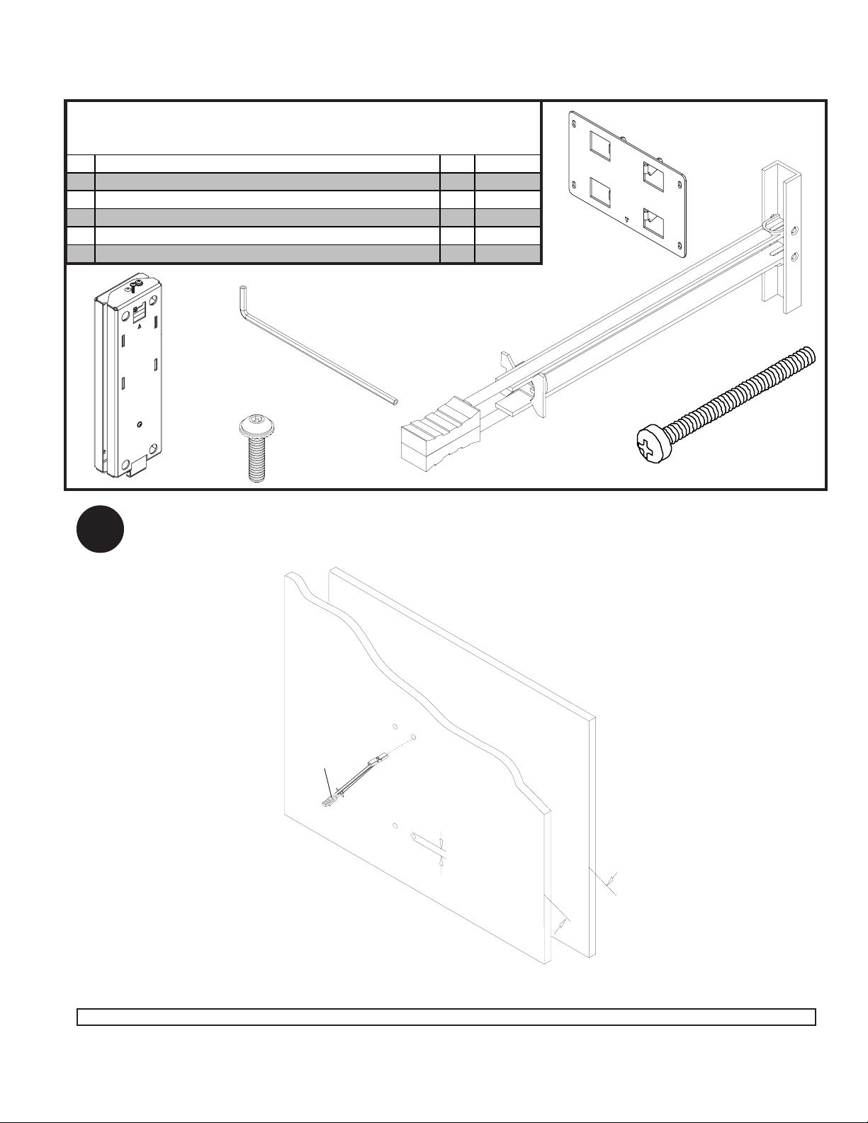
1
NOTE: T op of flange indicates the top of Samsung 23" screen. Arrow on wall template faces up.
Place wall template (AA) on wall (refer to MIS378 wall template instruction sheet). Level template and mark center
of mounting holes. Drill four 1/2" (13mm) dia. holes 2" (50mm) deep.
NOTE: Do not drill through neighboring wall as shown.
ARROW
LEVEL
FLANGE
Ø 1/2”
(13 mm)
NEIGHBORING WALL
WALL TEMPLATE (AA)
2”
(50 mm)
For customer care call (800) 865-21 12 or (708) 865-8870.
2 of 6
Visit the Peerless Web Site at www.peerlessmounts.com For customer care call 1-800-865-2112 or 708-865-8870.
ISSUED: 03-16-07 SHEET #: 124-9213-1
IMPORTANT! Read instruction sheet before you st art installation and assembly .
Before you start make sure all parts listed are included with your product.
Parts List
De scrip tion Qty. Part #
sc reen plat e 1 095-1449
A
wall mount 1 095-0454
B
M4 x 16 mm sock et pin serrated was her head screw 4 510-1087
C
toggler 4 560-9708
D
1/4-20 x 2.5" phill i ps screw 4 520-9521
E
4 mm s ecurity allen wrench 1 560-9646
F
D
F
B
A
2
C
Insert togglers (D) in pre-drilled holes following step 2 through 2-5.
D
Ø 1/2”
(13 mm)
E
2”
(50 mm)
3 of 6
Visit the Peerless Web Site at www.peerlessmounts.com For customer care call 1-800-865-2112 or 708-865-8870.
ISSUED: 03-16-07 SHEET #: 124-9213-1
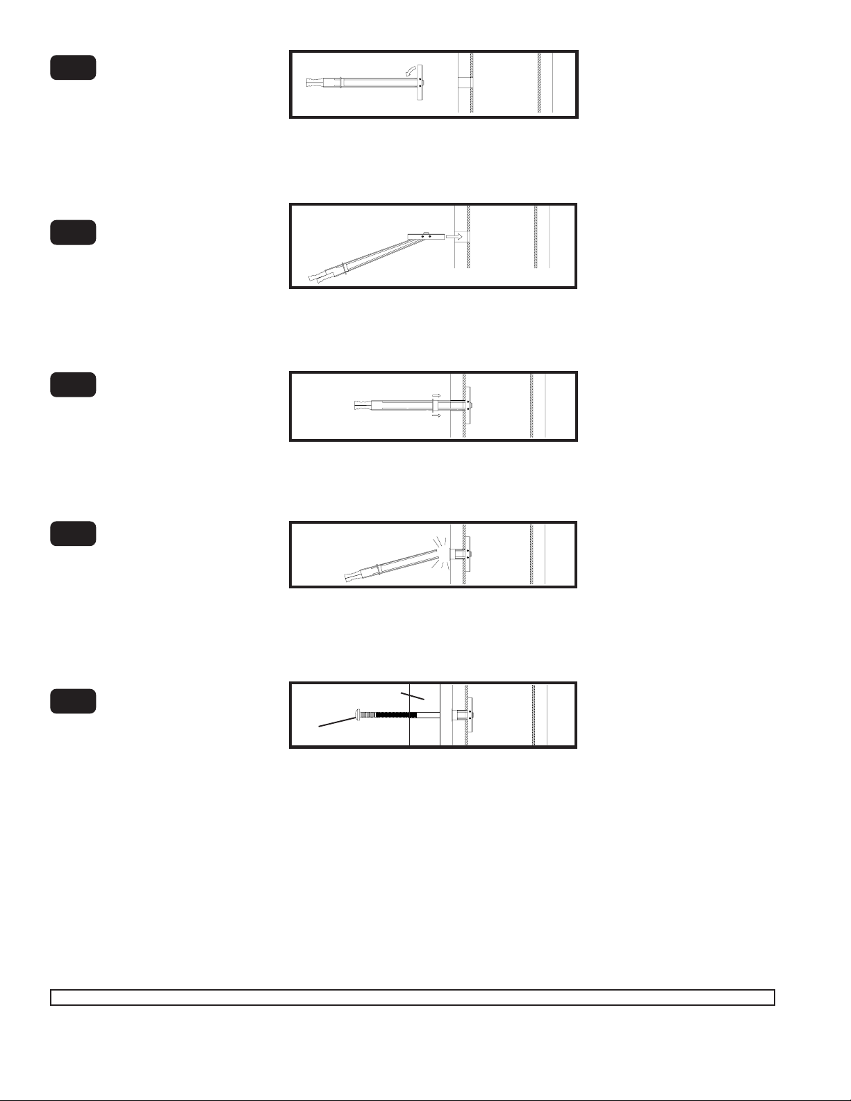
2-1
Pivot end of toggler (D).
D
2-2
2-3
2- 4
Push into hole.
Slide plastic cap forward
while pulling back firmly on
ring.
Break off excess.
E
wall mount
4 of 6
ISSUED: 03-16-07 SHEET #: 124-9213-1
2- 5
Visit the Peerless Web Site at www.peerlessmounts.com For customer care call 1-800-865-2112 or 708-865-8870.
Align wall mount with hole
in wall and fasten using
1/4-20 x 2.5”screw (E).
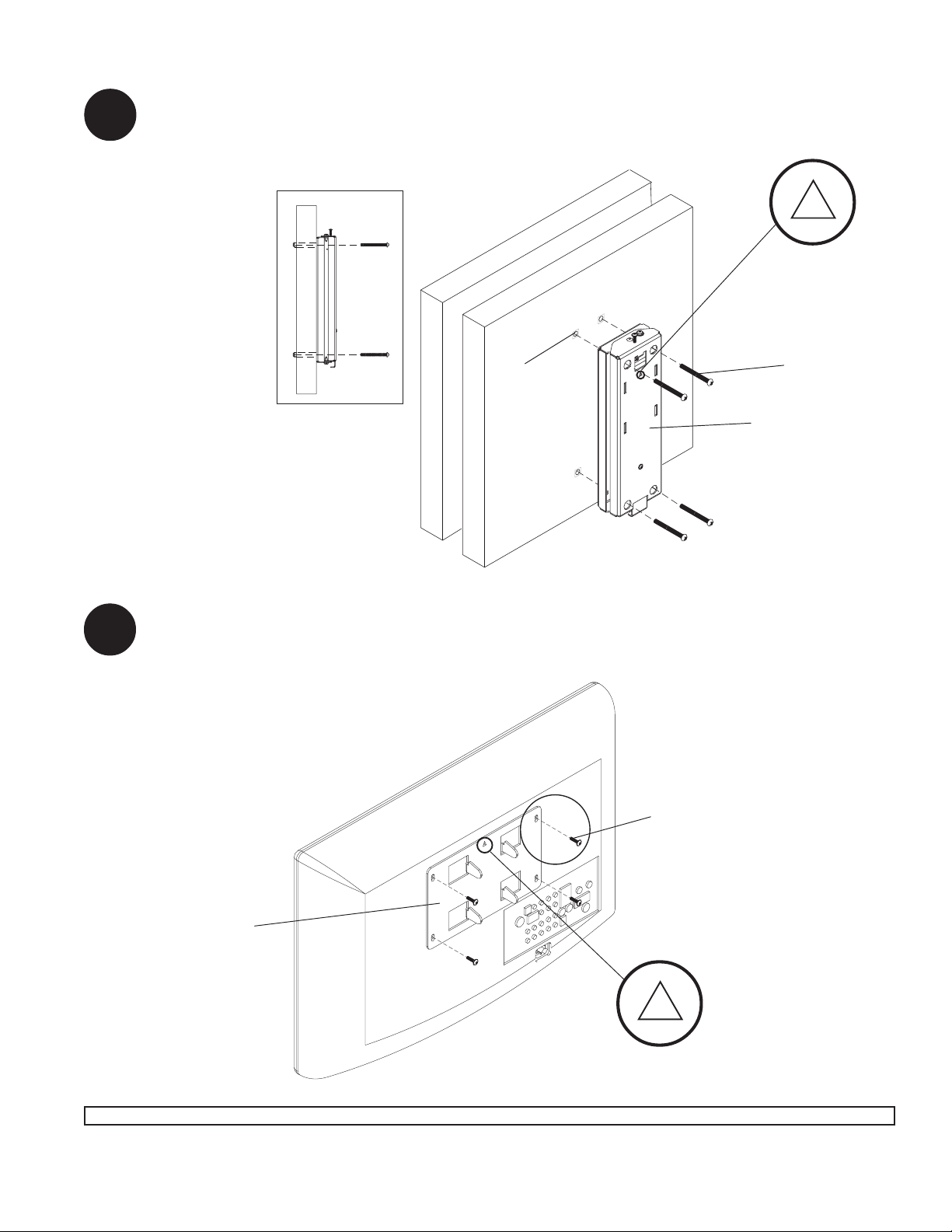
Attaching wall mount to surface
NOTE: Arrow on wall mount faces up.
Attach four 1/4 x 2.5” phillips screws (E) through wall mount (B) to supporting surface.
3
ARROW
Supporting Surface
SIDE VIEW
Attaching Screen Plate
NOTE: Arrow on screen plate faces up.
Attach four M4 x 16 mm socket pin serrated washer head screws (C) through screen plate (A) to
4
screen using 4mm security allen wrench (F).
Screen
D
E
B
C
A
ARROW
5 of 6
Visit the Peerless Web Site at www.peerlessmounts.com For customer care call 1-800-865-2112 or 708-865-8870.
ISSUED: 03-16-07 SHEET #: 124-9213-1
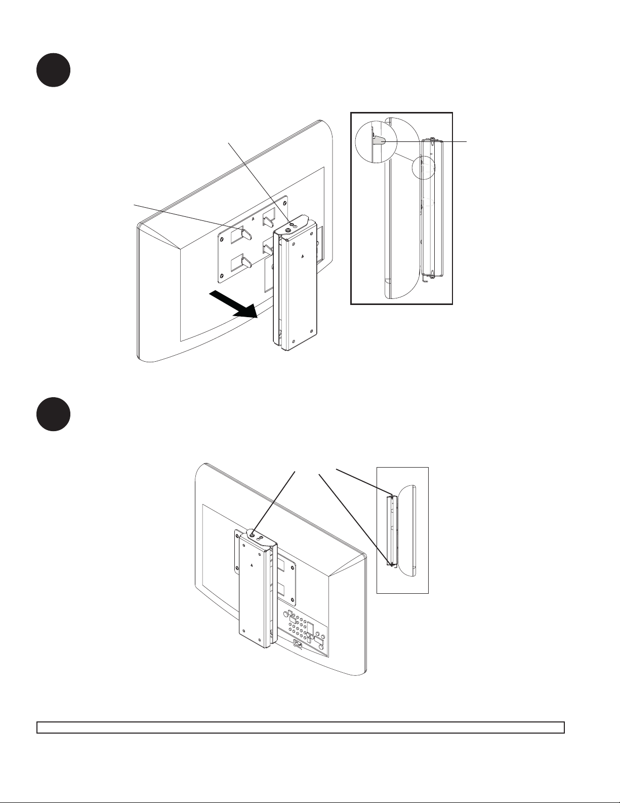
5
Attach screen to wall mount (B), using the hooks from screen plate as shown in fig. 5.1. You will hear a
locking sound when screen plate engages wall mount. Fully tighten the M4 x 16 mm socket pin serrated
washer head screw on the wall mount (B), to secure.
fig. 5.1
M4 x 16 mm socket pin
serrated washer head screw.
screen plate hook.
screen plate hook.
Screen
B
Supporting surface not shown for clarity .
OPTIONAL - Swivel Friction Adjustment
T o decrease friction for wall mount swivel, loosen the two swivel friction screws on wall mount assembly (B)
6
indicated below. Swivel mount to desired position and retighten screws.
SWIVEL FRICTION SCREWS
SIDE VIEW
B
6 of 6
Visit the Peerless Web Site at www.peerlessmounts.com For customer care call 1-800-865-2112 or 708-865-8870.
© 2007 Peerless Industries, Inc. All rights reserved.
Peerless is a registered trademark of Peerless Industries, Inc.
All other brand and product names are trademarks or registered trademarks of their respective owners.
ISSUED: 03-16-07 SHEET #: 124-9213-1
 Loading...