


Installation and Assembly:
20" Column Mount
Model: MIS374A
Max Load Capacity: 80 lb (36.3 kg)
3215 W. North Ave. • Melrose Park, IL 60160 • (800) 729-0307 or (708) 865-8870 • Fax: (708) 865-2941 • www.peerlessmounts.com
ISSUED: 03-30-07 SHEET #: 124-9053-1
Note: Read entire instruction sheet before you start installation and assembly.
WARNING
• Do not begin to install your Peerless product until you have read and understood the instructions and warnings
contained in this Installation Sheet. If you have any questions regarding any of the instructions or warnings, please
call Peerless customer care at 1-800-865-21 12.
• This product should only be installed by a qualified professional.
• Make sure that the column will safely support the combined load of the equipment and all attached hardware and
components.
• Never exceed the Maximum Load Capacity of 80 lb (36.3 kg).
• Always use an assistant or mechanical lifting equipment to safely lift and position equipment.
• Tighten screws firmly , but do not overtighten. Overtightening can damage the items, greatly reducing their holding
power.
Tools Needed for Assembly
• phillips screwdriver
• drill
• 1/4" bit for concrete
• level
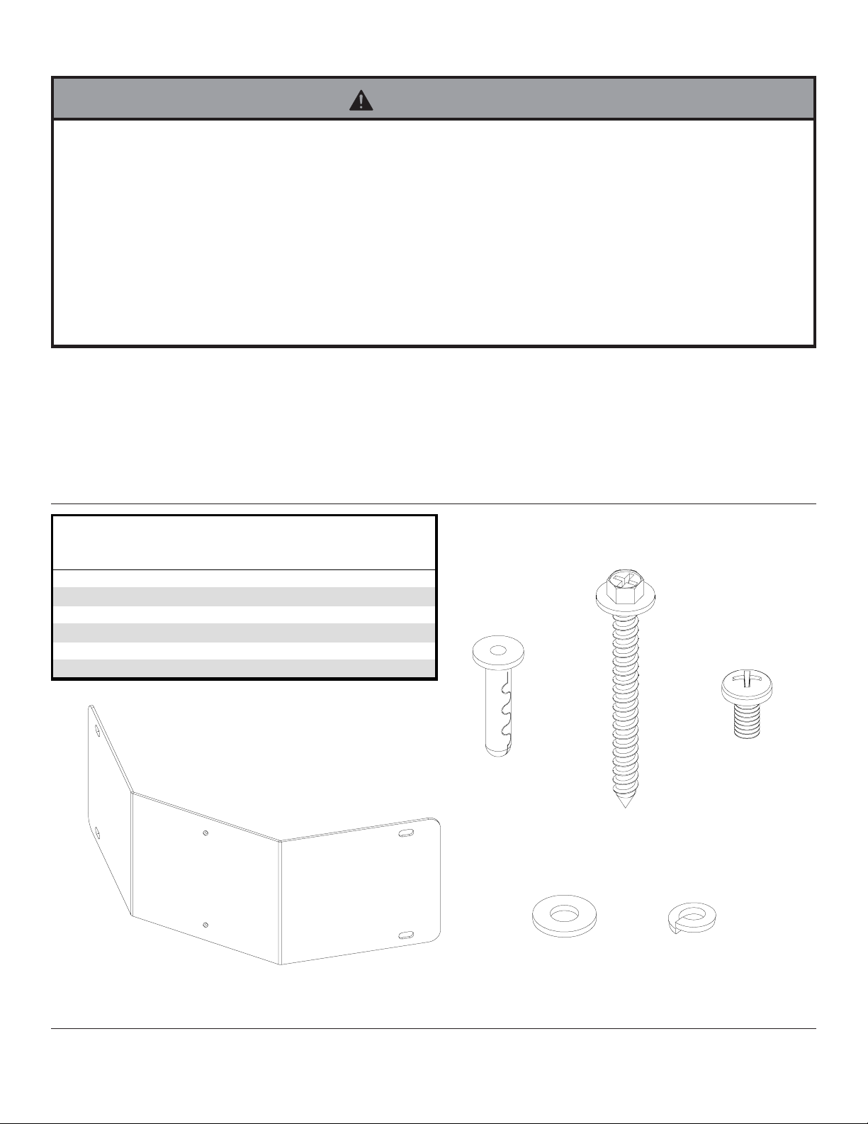
Part s Li st
Description Qty Part #
column plat e 1 201-1291
A
Alligator® anchor 4 590-0097
B
#14 x 2-1/ 2" hex head wood s crew 4 5S1-015-C03
C
1/4-20 x 1/2 phillips s c rew 2 510-9108
D
1/4" flat was her 2 540-9440
E
1/4" spli t was her 2 540-9402
F
MIS374A
A
D
B
C
For customer care call (800) 865-21 12 or (708) 865-8870.
2 of 4
E
F
ISSUED: 03-30-07 SHEET #: 124-9053-1

Installation to Solid Concrete Column
WARNING
• Concrete must be 2000 psi density minimum. Lighter density concrete may not hold concrete anchor .
• Make sure that the column will safely support the combined load of the equipment and all attached hardware and
components.
Make sure that column plate (A) is level, use it as a
1
template to mark four mounting holes. Drill four 1/4"
(6 mm) dia. holes to a minimum depth of 2-1/2"
(64 mm). Insert anchors (B) in holes flush with
column as shown (right). Place column plate over
anchors and secure with four #14 x 2-1/2" screws
(C). Level, then tighten all fasteners.
WARNING
• Tighten screws so that column plate is firmly attached,
but do not overtighten. Overtightening can damage
screws, greatly reducing their holding power.
• Never tighten in excess of 80 in. • lb (9 N.M.).
WARNING
1
concrete
surface
B
Drill holes and insert anchors (B).
2
A
C
Place plate (A) over anchors (B) and secure with screws (C).
3
B
• Always attach concrete expansion anchors directly to
load-bearing concrete.
• Never attach concrete expansion anchors to concrete
covered with plaster, drywall, or other finishing material. If mounting to concrete surfaces covered with a
finishing surface is unavoidable, the finishing surface
must be counterbored as shown below. Be sure
concrete anchors do not pull away from concrete
when tightening screws. If plaster/drywall is thicker
than 5/8", custom fasteners must be supplied by
installer.
column
plate
CORRECT
concrete
plaster/
dry wall
CUT A WA Y VIEW
INCORRECT
column
plate
concrete
plaster/
dry wall
3 of 4
C
A
B
concrete
column
ISSUED: 03-30-07 SHEET #: 124-9053-1

Installation of ST 630 to Column Plate
Note: Model ST 630 is required for assembly.
Tilt assembly of ST 630 is required to complete step 2.
Attach tilt assembly to column plate (A) using two 1/4-20 x 1/2 phillips screws (D), two split washers (F) and two flat
2
washers (E).
TILT
ASSEMBLY
A
E
F
D
Refer to Attaching Adapter Plate to Flat Panel Screen section of ST 630 instruction manual to complete assembly.
4 of 4
All other brand and product names are trademarks or registered trademarks of their respective owners.
ISSUED: 03-30-07 SHEET #: 124-9053-1
© 2007, Peerless Industries, Inc. All rights reserved.
 Loading...