

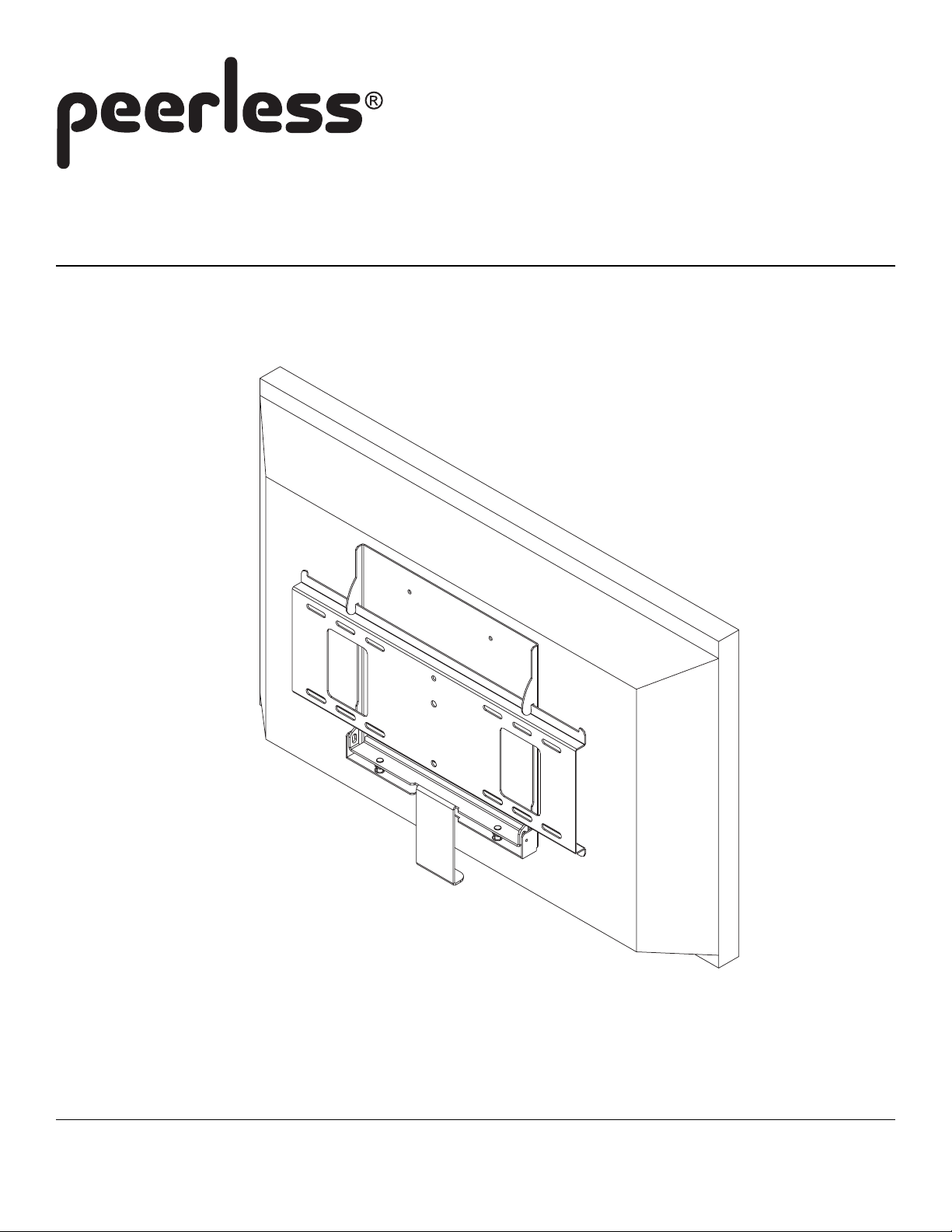
Installation and Assembly:
MIS343
3215 W. North Ave. • Melrose Park, IL 60160 • (800) 865-2112 or (708) 865-8870 • Fax: (708) 865-2941 • www.peerlessmounts.com
ISSUED: 02-01-07 SHEET #: 124-9042-2 04-13-07
4
7
3
1
4
Note: Read entire instruction sheet before you start installation and assembly.
WARNING
• Do not begin to install your Peerless product until you have read and understood the instructions and warnings
contained in this Installation Sheet. If you have any questions regarding any of the instructions or warnings, please
call Peerless customer care at 1-800-729-0307.
• This product should only be installed by someone of good mechanical aptitude, has experience with basic building
construction, and fully understands these instructions.
• Make sure that the supporting surface will safely support the combined load of the equipment and all attached hardware and components.
• Always use an assistant or mechanical lifting equipment to safely lift and position equipment.
• Tighten screws firmly , but do not overtighten. Overtightening can damage the items, greatly reducing their holding
power.
Tools Needed for Assembly
• phillips screwdriver
• drill
• 5/32" bit
• level
IMPORTANT! Read entire instruction sheet before you start inst allation and assembly .
NOTE: Some parts may appear slightly different than illustrated.
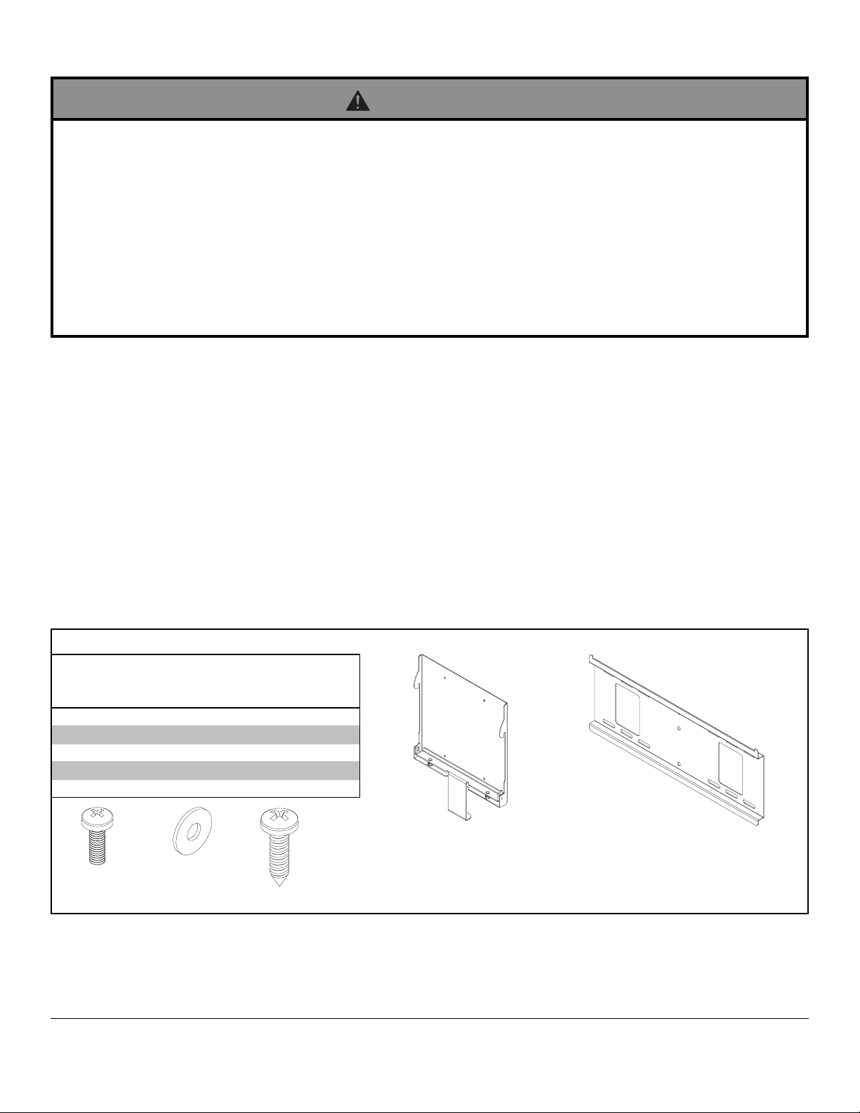
Parts List
De scri ption Qty. Par t #
adapter brack et 1 124-078
A
wall plat e 1 200-179
B
M4 x 12 mm phil l i ps screw 4 504-901
C
#8 SAE flat washer 4 540-100
D
# 14 x 3/ 4 wood screw 4 500-100
E
MIS 343
A
CDE
Before you start make sure all parts listed are included with your product.
For customer care call (800) 729-0307 or (708) 865-8870.
B
2 of 3
ISSUED: 02-01-07 SHEET #: 124-9042-2 04-13-07

WARNING
• Installer must verify that the supporting surface will safely support the combined load of the equipment and all attached
hardware and components.
• Tighten wood screws so that wall plate is firmly attached, but do not overtighten. Overtightening can damage the
screws, greatly reducing their holding power.
• Never tighten in excess of 80 in. • lb (9 N.M.).
• Make sure that the armoire is securely fastened to the wall so tipping will not occur .
• Hardware provided is for attachment of mount through plywood. Installers are responsible to provide hardware for other
types of mounting situations.
Installation to ¾” Plywood
Place wall plate (B) on plywood as a
1
template. The top mounting slots should
be located above the desired screen
center as indicated by dimension X in
figure 1.1. Level plate (B), and mark the
center of the four mounting holes. Drill four
5/32" (4 mm) dia. holes 3/4" (19 mm)
deep. Make sure that the wall plate is
level, secure it using four #14 x 3/4" wood
screws (E) as shown in figure 1.2.
X
CS
CS = center of screen
fig. 1.1
B
PLYWOOD
NOTE: Make sure there is enough space
for screen to be installed and removed
safely.
Installation of Screen to Adapter Plate
T o prevent scratching the screen, set a cloth on a flat,
2
level surface that will support the weight of the screen.
Place screen face side down. Attach adapter bracket
(A) to screen using #8 SAE flat washer (D) and M4 x
12 mm phillips screw (C).
SCREEN
D
C
E
Installing Screen to Wallplate
Hook screen onto wallplate (B) and snap bottom of
3
adapter bracket (A) onto the wallplate (B).
NOTE: T o release, pull down on locking spring bracket as
you pull screen out and up off of wallplate (B).
A
LOCKING
SPRING
BRACKET
fig. 1.2
SCREEN
A
B
3 of 3
All other brand and product names are trademarks or registered trademarks of their respective owners.
ISSUED: 02-01-07 SHEET #: 124-9042-2 04-13-07
SUPPORTING SURF ACE
NOT SHOWN FOR
CLARITY
© 2007, Peerless Industries, Inc. All rights reserved.
 Loading...