

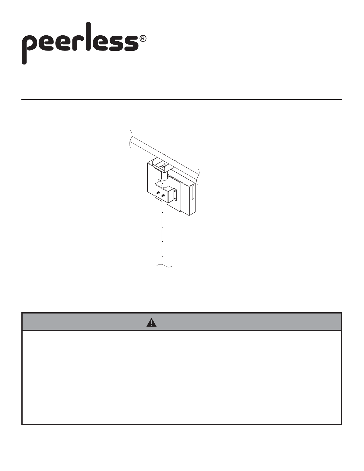
Installation and Assembly:
Pole PC Mount
Model: MIS488
Max Load Capacity: 25 lb (1 1.3 kg)
Note: Read entire instruction sheet before you start installation and assembly .
WARNING
• Do not begin to install your Peerless product until you have read and understood the instructions and warnings
contained in this Installation Sheet. If you have any questions regarding any of the instructions or warnings, please
call Peerless customer care at 1-800-729-0307.
• This product should only be installed by a qualified professional.
• Make sure that the wall will safely support the combined load of the equipment and all attached hardware and components.
• Never exceed the Maximum Load Capacity of 25 lb (1 1.3 kg).
• Always use an assistant or mechanical lifting equipment to safely lift and position equipment.
• Tighten screws firmly , but do not overtighten. Overtightening can damage the items, greatly reducing their holding
power.
2300 White Oak Circle. • Aurora, IL 60502 • (800) 729-0307 or (708) 865-8870 • Fax: (708) 865-2941 • www.peerlessmounts.com
ISSUED: 11-19-07 SHEET #: 124-9135-2 01-06-11
Note: Read instruction sheet before you st art installation and assembly .
1
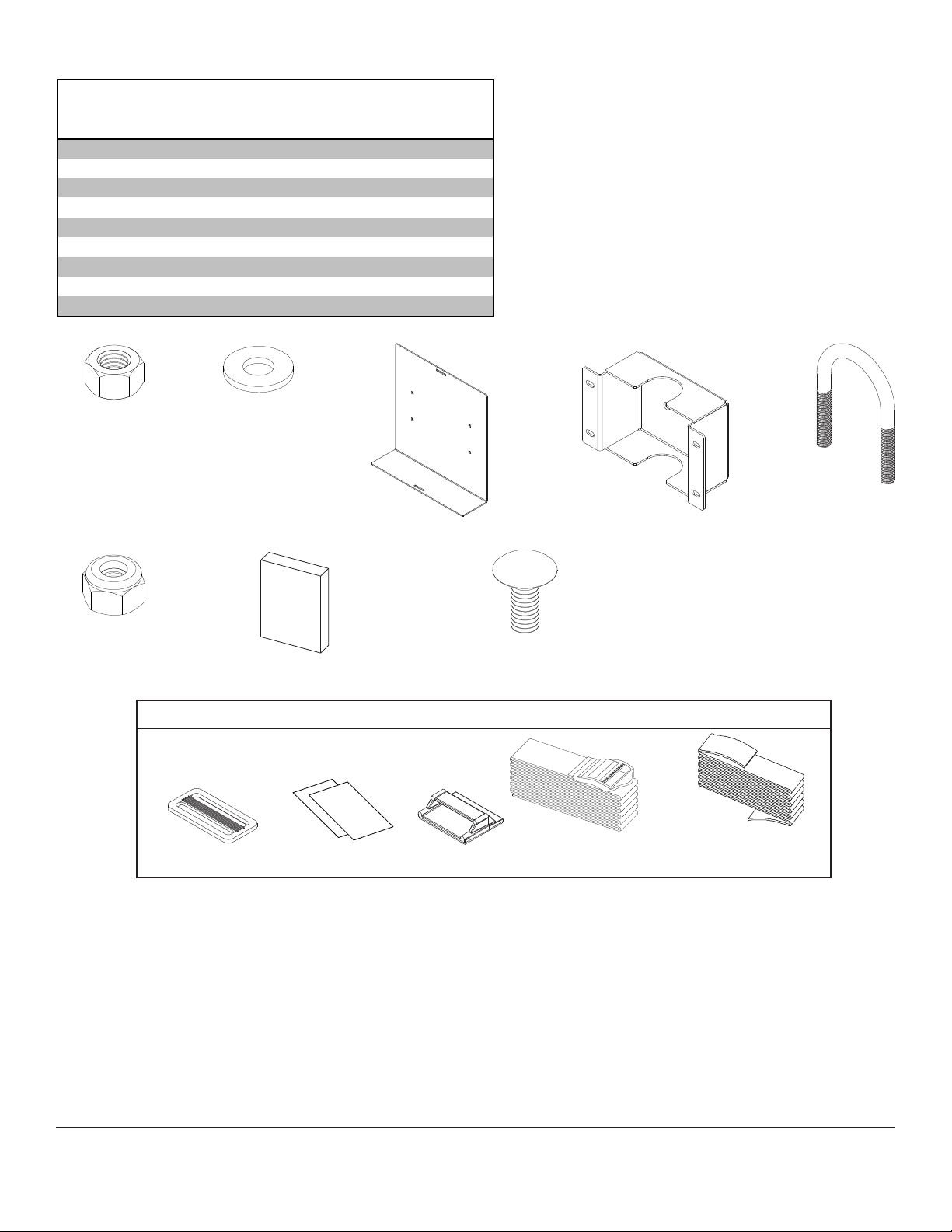
Parts List
De scrip tion Qty. P art #
3/8-16 hex nut 2 530-9310
I
washer 2 540-9407
N
PC bracket 1 124-T1133
Q
3/8-1 6 x 3. 25" u-bolt 1 560-1060
S
1/4-20 nyl oc k nut 4 530-9413
T
PC mount i ng bracket 1 124-T1134
U
bumper 6 590-1159
W
1/4-2 0 x 5/ 8" carrai g e bol t 4 520-1175
Y
safety bel t 1 170-8039-
Z
T
N
W
Y
Safety Belt Kit (Z)
UIQ
S
TRI-BAR BELT CLIP CLEAR STRIPS BELT GUIDE
2 of 4
BELT WITH
CINCH BUCKLE
Note: Some parts may appear slightly different than illustrated.
ISSUED: 11-19-07 SHEET #: 124-9135-2 01-06-11
BELT WITHOUT
CINCH BUCKLE
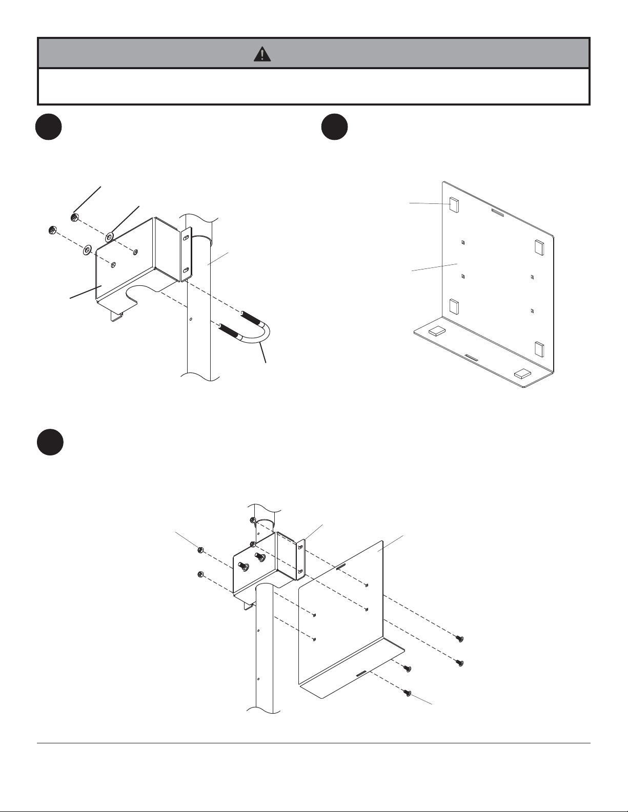
WARNING
• Installer must verify that the supporting surface will safely support the combined weight of all attached equipment and
hardware.
Attach PC mounting bracket (U) to
1 2
using four washers (N) and four hex nuts (I).
existing pole
I
N
EXISTING POLE
U
S
Attach six bumper strips (W) to PC bracket (Q).
W
Q
Attach PC bracket (Q) to PC mounting bracket (U) using four 1/4-20 nylock nuts (T) and four 1/4-20 x 5/8" carraige
3
bolts (Y).
T
U
Q
Y
3 of 4
ISSUED: 11-19-07 SHEET #: 124-9135-2 01-06-11

NOTE: Use safety belt (Z) instruction in conjuction with this step.
4
Fasten clear strips to the two slots in PC bracket (Q). Set HD box into computer plate (B). Fasten belt with
cinch buckle to belt without cinch buckle. Place tri-bar belt clips and belt guide onto belt as shown in the safety
belt instructions. Feed the ends of the belt through the PC bracket (Q) slots and through tri-bar belt clip. Cinch
the end of the belt so that the PC is securely held.
NOTE: Trim of f the end of the belt if necessary , then lightly burn the end of the belt to prevent fraying.
BELT WITH
CINCH BUCKLE
Q
BELT WITHOUT
CINCH BUCKLE
PC
BELT WITH
CINCH BUCKLE
CLEAR STRIPS
BELT WITHOUT
CINCH BUCKLE
BELT GUIDE
PC
TRI-BAR BELT CLIP
4 of 4
All other brand and product names are trademarks or registered trademarks of their respective owners.
ISSUED: 11-19-07 SHEET #: 124-9135-2 01-06-11
© 2011, Peerless Industries, Inc. All rights reserved.
 Loading...