


Installation and Assembly:
Dual Arm Desktop Mount with Desk Clamp and Grommet for
19" - 30" LCD Screens
Models: LCT620AD
GROMMET INSTALLATION DESK CLAMP INSTALLATION
Max Load Capacity per arm: 15 lbs (6.8 kg)
2300 White Oak Circle • Aurora, Il 60502 • (800) 865-2112 • Fax: (800) 359-6500 • www.peerless-av.com
ISSUED: 07-25-11 SHEET #: 090-9205-5 11-30-12

NOTE: Read entire instruction sheet before you start installation and assembly.
WARNING
• Do not begin to install your Peerless product until you have read and understood the instructions and warnings
contained in this Installation Sheet. If you have any questions regarding any of the instructions or warnings, please
call Peerless customer care at 1-800-865-2112.
• This product should only be installed by someone of good mechanical aptitude, has experience with basic building
construction, and fully understands these instructions.
• Make sure that the supporting surface will safely support the combined load of the equipment and all attached
hardware and components.
• Never exceed the Maximum Load Capacity. See page 1.
• Always use an assistant or mechanical lifting equipment to safely lift and position equipment.
• Tighten screws fi rmly, but do not overtighten. Overtightening can damage the items, greatly reducing their holding
power.
• This product is intended for indoor use only. Use of this product outdoors could lead to product failure and personal
injury.
Tools Needed for Assembly
• phillips screwdriver
• drill
• 3/8" (10mm) drill bit
Table of Contents
Parts List.................................................................................................................................................................................3
Installation to Mounting Surface .............................................................................................................................................4
Attaching Arm Assembly to Screen ........................................................................................................................................5
Cable Management ................................................................................................................................................................6
2 of 9
ISSUED: 07-25-11 SHEET #: 090-9205-5 11-30-12
y
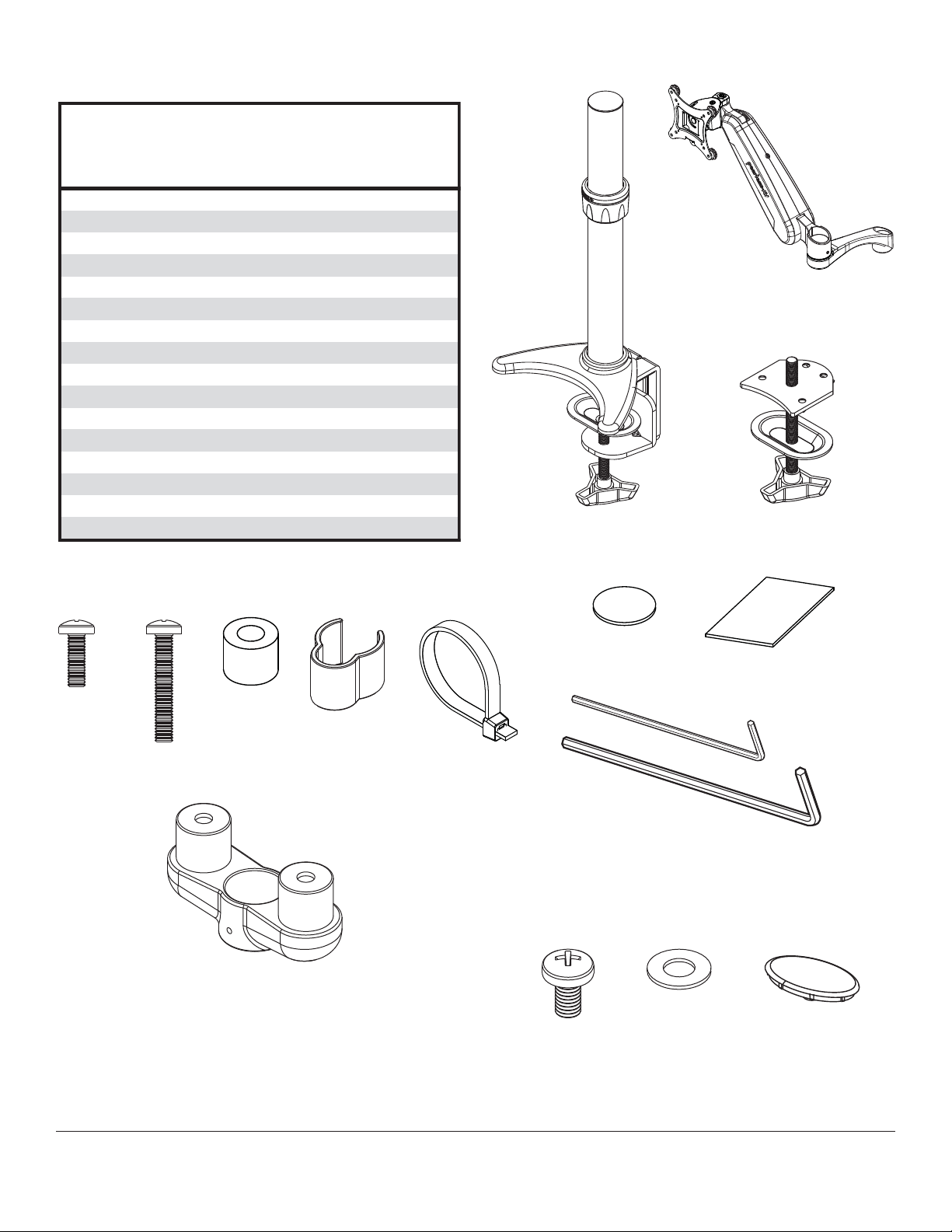
Before you begin, make sure all parts shown are included
with your product.
A
Parts List
LCT620AD
Description
A column assembly 1
B double link arm assembly 2
C grommet assembly 1
D round rubber pads 2
E square rubber pads
F M4 x 12 mm phillips screw
G M4 x 25 mm phillips screw
H spacer 8
I 4 mm allen wrench 1
J 2.5 mm allen wrench 1
K cable clip
L cable tie
M M6 x 12 mm phillips screw
N M6 plastic washer
O cover
P dual arm support
Parts may appear slightly different than illustrated.
FGH
K
Qt
B
2
8
8
1
5
2
2
2
1
D
C
E
L
P
3 of 9
J
I
MN O
ISSUED: 07-25-11 SHEET #: 090-9205-5 11-30-12

Clamp Installation Method
Apply four rubber pads (D, E) to bottom of column
1
assembly (A) as shown below. Attach column
assembly (A) to mounting surface with a maximum
thickness of 3".
Skip to step four.
Grommet Installation Method
Remove clamp assembly from column assembly
1
(A) as shown in fi gure 1.1. Remove mounting plate
from grommet assembly (C) and attach to column
assembly (A) with four M6 x 8mm screws using
4mm allen wrench (I) as shown in fi gure 1.2.
fi g. 1.1
A
M6 X 8MM
SCREWS
D
E
Apply four rubber pads (D, E) to bottom of column
2 3
assembly (A) as shown below.
A
fi g. 1.2
A
CLAMP
ASSEMBLY
MOUNTING
PLATE
M6 X 8MM
SCREWS
Drill a 3/8" (10mm) dia. hole through mounting
surface with a maximum thickness of 3". Place
column assembly (A) on mounting surface and
secure using grommet assembly (C).
A
E
D
4 of 9
A
C
ISSUED: 07-25-11 SHEET #: 090-9205-5 11-30-12

Attaching Adapter Plate to Screen
WARNING
• Tighten screws so adapter plate is fi rmly attached. Do not tighten with excessive force. Overtightening can cause
stress damage to screws, greatly reducing their holding power and possibly causing screw heads to become
detached. Tighten to 40 in. • lb (4.5 N.M.) maximum torque.
• If screws don't get three complete turns into the screen inserts or if screws bottom out and arm is still not tightly
secured, damage may occur to screen or product may fail.
OPTIONAL: To disassemble adapter plate from arm assembly (B), remove knob attached to bottom of adapter
4
plate as shown in fi gure 4.1.
4-1
To prevent scratching the screen, set a cloth on a fl at, level surface that will support the weight of the screen.
Place screen face side down. If screen has knobs on the back, remove them to allow the adapter plate to be
attached. Place adapter plate on back of screen.
Choose hole pattern as shown in detail 1.
FOR DISPLAYS WITH FLAT BACKS: Attach adapter plate to display using four knobs or remove four knobs and
secure with 12mm screws (F) as shown in fi gure 4.2.
FOR DISPLAYS WITH RECESSED BACKS: Remove knobs from adapter plate and attach to display using four
25mm screws (G) and four spacers (H) as shown in fi gure 4.3.
fi g. 4.1
ADAPTER PLATE
fi g. 4.2
ADAPTER PLATE
F
or KNOBS
B
KNOB
VESA 100mm
VESA 75mm
VESA 75mm
DETAIL 1
VESA 100mm
5 of 9
ADAPTER PLATE
fi g. 4.3
G
H
ISSUED: 07-25-11 SHEET #: 090-9205-5 11-30-12

Insert dual arm support (P) onto column assembly (A) fl ush against lock collar as shown in fi gure 5.1. Loosen and
5
position lock collar to desired height and retighten.
arm assembly (B) onto dual arm support (P) as shown in fi gure 5.2.
Insert
Tighten set screws on dual arm support (P) and arm assembly (B) using 2.5mm allen wrench (J) as shown in fi gure
5.3.
fi g. 5.1
P
LOCK
COLLAR
Secure arm assembly (B) to dual arm support with
6
one cover (O), one M6 x 12mm phillips screw (M),
and one M6 plastic washer (N).
Repeat steps fi ve and six for second arm
assembly (B).
fi g. 5.2 fi g. 5.3
B
B
SET SCREW
SET SCREWS
Hook adapter plate onto arm assembly (B).
7
B
O
N
M
6 of 9
ADAPTER PLATE
B
ISSUED: 07-25-11 SHEET #: 090-9205-5 11-30-12

Reinstall knobs through back of arm assemblies (B) and secure into back of adapter plates. Cables may be routed
8
using cavity in arm assembly (B) and cable clip (K). Remove the cable cover on arm assembly (B) by pressing
fi rmly in the middle of the cable cover and then pulling the fl anges of the cable cover. Route the cables in arm
assembly (B) and then reinstall the cable cover.
B
KNOB
CABLE
COVER
FLANGES
B
K
B
CABLES
K
7 of 9
ISSUED: 07-25-11 SHEET #: 090-9205-5 11-30-12

To lock down rotation, tighten set screw shown in detail 2.
9
To lock down tilt, tighten screw shown in detail 3.
To lock down swivel, tighten screw shown in detail 4.
To lock down height adjustment, tighten set screw shown in detail 5.
SET SCREW
DETAIL 2
360°
TILT SCREW
DETAIL 3
+80/-20°
DETAIL 4
SWIVEL
SCREW
+/- 6.25"
180°
SET SCREW
DETAIL 5
8 of 9
All other brand and product names are trademarks or registered trademarks of their respective owners.
ISSUED: 07-25-11 SHEET #: 090-9205-5 11-30-12
© 2012 Peerless Industries, Inc. All rights reserved.

LIMITED FIVE-YEAR WARRANTY
Peerless Industries, Inc. (“Peerless”) warrants to original end-users of Peerless® products will be free from defects in material and workmanship, under normal
use, for a period of fi ve years from the date of purchase by the original end-user (but in no case longer than six years after the date of the product’s manufacture).
In no event shall the duration of any implied warranty of merchantability or fi tness for a particular purpose be longer than the period of the applicable
express warranty set forth above. Some states do not allow limitations on how long an implied warranty lasts, so the above limitation may not apply to you.
This warranty does not cover damage caused by (a) service or repairs by the customer or a person who is not authorized for such service or repairs by Peerless,
(b) the failure to utilize proper packing when returning the product, (c) incorrect installation or the failure to follow Peerless’ instructions or warnings when installing,
In no event shall Peerless be liable for incidental or consequential damages or damages arising from the theft of any product, whether or not secured
by a security device which may be included with the Peerless® product. Some states do not allow the exclusion or limitation of incidental or consequential
This warranty is in lieu of all other warranties, expressed or implied, and is the sole remedy with respect to product defects. No dealer, distributor, installer or other
person is authorized to modify or extend this Limited Warranty or impose any obligation on Peerless in connection with the sale of any Peerless® product.
At its option, Peerless will repair or replace, or refund the purchase price of, any product which fails to conform with this warranty.
using or storing the product, or (d) misuse or accident, in transit or otherwise, including in cases of third party actions and force majeure.
damages, so the above limitation or exclusion may not apply to you.
This warranty gives specifi c legal rights, and you may also have other rights which vary from state to state.
www.peerless-av.com
© 2012 Peerless Industries, Inc.
9 of 9
ISSUED: 07-25-11 SHEET #: 090-9205-5 11-30-12
 Loading...