

Page 1

587M
6400
Automatic Isoperibol Calorimeter
Operating Instruction Manual
For models produced after October 2010
Page 2

Page 3

Table of Contents6400
Preface 4
Scope 4
Related Instructions 4
Purpose 4
Explanation of Symbols 5
Safety Information 5
Intended Usage 5
General Specifications 6
Environmental Conditions 6
Provisions for Lifting and Carrying 6
Cleaning & Maintenance 6
Chapter 1 8
Installation 8
Environmental Conditions 8
Swagelok Tube Fittings 8
Required Consumables, Utilities and Power Requirements 9
Electrical Connection 9
Front Panel Meter 9
Water Connection 11
Gas Connection 12
Bomb Exhaust Connections 12
Communication Connections 13
Printer Connections 13
Balance Connections 13
Chapter 2 16
Quick Start 16
Initial Fill 16
Quick Start 16
Chapter 3 18
Operation 18
Menu System 18
Menu Keys 18
Control Keys 18
Programming 19
Default Settings 19
Sample Preparation 19
Test Process 22
Closing the bomb 22
Cool/Rinse 26
Drain
Fill Cycle 23
Pre-Period 24
Bomb Firing 25
Post-Period 25
Chapter 4 28
Menu Descriptions 28
Main Menu 28
Calorimeter Operation Menu 28
Temperature vs. Time Plot 29
Temperature Plot Setup Menu 29
Operating Controls Menu 30
Spiking Controls 30
Bomb Rinse Tank Controls 31
Program Information and Control Menu 32
Software & Hardware Info 32
User/Factory Settings 33
Calibration Data and Controls Menu 34
Bomb 1 35
Control Plot Chart Plot 35
Thermochemical Corrections Menu 36
Calculation Factors Menu 37
Net Heat/Dry Heat Factors 38
Data Entry Controls Menu 38
Net Heat Data Entry Controls 39
Auto Sample ID Controls 39
Moisture Data Entry Controls 40
Preweigh Sample ID Controls 40
Reporting Controls Menu 40
Communication Controls Menu 41
Balance Port Communications 41
Balance Port Settings 42
File Management Menu 43
Run Data File Manager 43
Diagnostics Menu 44
Data Logger Controls 44
Data Log Items 45
User Defined Buttons 45
I/O Diagnostics:
www.parrinst.com
1
Page 4

Table of Contents
Chapter 5 46
Reports 46
Reports 46
Chapter 6 48
Standardizations 48
Standardizing the Calorimeter 48
Standard Materials 48
Automatic Statistical Calculations 48
Chapter 7 52
Calculations 52
Calculating the Heat of Combustion 52
General Calculations 52
Thermochemical Corrections 52
ASTM and ISO Methods Differ 53
Thermochemical Calculation Details 54
Acid and Sulfur Corrections 54
ASTM Treatment for Acid and Sulfur 56
ISO Calculations 56
Spiking Samples 57
Conversion to Other Moisture Bases 57
Conversion to Net Heat of Combustion 57
Chapter 10 70
Maintenance 70
Inspection of Critical Sealing Surfaces 70
Bomb Removal 70
Fuses 71
Daily Maintenance 71
Quarterly Maintenance 71
50 to 100 Test Maintenance 71
500 Test Maintenance 71
5000 Test Maintenance 72
6400 Maintenance Checklist 73
Chapter 11 74
Troubleshooting 74
Bomb Exhaust Troubleshooting 74
Jacket Temperature Troubleshooting 75
Error List 76
Chapter 12 78
Technical Service 78
Return for Repair 78
Chapter 13 80
Chapter 8 58
Computer Communications 58
Computer Connections 58
Samba Server Feature (Optional) 59
Bar Code Port 66
Chapter 9 68
Memory Management 68
Clearing Memory 68
Removable SD Memory 68
2
Parr Instrument Company
Parts Lists 80
Principal Assemblies in Calorimeter 80
A1250DD2 Controller Assembly 80
A1265DD Bucket and Stirrer Tube Assembly 80
A1255DD Bucket Stirrer Assembly 81
A1266DD Cover Assembly 81
A1457DD Accessory/Installation Kit 81
Chapter 14 82
Drawings 82
1138 Parts Diagram Key 83
Chapter 15 104
Tables 104
Page 5

Table of Contents6400
Figures
Figure 1-1
Swagelok Tube Fittings 8
Figure 1-2
6400 Calorimeter Back Panel 10
Figure 1-3
6400 External Plumbing 11
Figure 1-4
6400 Calorimeter Peripherals 14
Figure 1-5
Multiple Alternate Configurations 14
Figure 3-1
Volatile Sample Technique 21
Figure 3-2
Cotton Thread Assembly 22
Figure 3-3
Bucket Fill Flow Diagram 23
Figure 3-4
Pre-Period/Post-Period Flow Diagram 24
Figure 3-5
Rinse & Cool Flow Diagram 26
Figure 3-6
Drain Flow Diagram 27
Figure 14-1
1138 Parts Diagram 82
Figure 14-2
6400 Cutaway Right 84
Figure 14-3
6400 Cutaway Left 85
Figure 14-4
6400 Cover Open 86
Figure 14-5
A1250DD2 Control Schematic 87
Figure 14-6
A1251DD Oxygen Solenoid Assembly 88
Figure 14-7
A1447DD Water Solenoid Assembly 88
Figure 14-8
A1456DD Rinse Valve Assembly 89
Figure 14-9
6400 Internal Plumbing Diagram 90
Figure 14-10
6400 Water Tank and Jacket Cooling Solenoid 91
Figure 14-11
A1455DD Propeller Assembly 92
Figure 14-12
A1448DD Temperature Control Assembly 92
Figure 14-13
A1268DD Stirrer Motor and Mount 93
Figure 14-14
6400 Bucket Assembly 94
Figure 14-15
6400 Air Can Assembly, Cutaway Left 95
Figure 14-16
6400 Air Can Assembly, Cutaway Front 96
Figure 14-17
A1450DD Bomb Head Assembly, View 1 97
Figure 14-18
A1450DD Bomb Head Assembly, View 2 98
Figure 14-19
A1050DD Rinse Collection Assembly 99
Figure 14-20
Wiring Diagram 100
Figure 14-21
Wiring Diagram 101
Figure 14-22
Fuse Diagram 102
Tables
Table 6-1
Calorimeter Control Limit Values in J/g When Benzoic
Acid is Used as a Test Sample 49
Table 6-2
Calorimeter Control Limit Values in cal/g When Benzoic
Acid is Used as a Test Sample 50
Table 6-3
Calorimeter Control Limit Values in BTU/lb When Benzoic
Acid is Used as a Test Sample 51
Table 8-1
6400 Data File Naming Convention 66
Table 8-2
6400 Calorimeter Run Data Template 67
Table 15-1
Factory Default Settings 104
Table 15-2
Settings for ISO & BSI Methods 106
www.parrinst.com
3
Page 6
Preface
Preface
Scope
This manual contains instructions for installing and
operating the Parr 6400 Calorimeter. For ease of
use, the manual is divided into 15 chapters.
Related Instructions
Additional instructions concerning the installation
and operation of various component parts and
peripheral items used with the 6400 Calorimeter
should be made a part of these instructions. Additional instructions for the optional printer are found
in the respective printer package and should be
made a part of this book.
1. Installation
2. Quick Start
3. Operation
4. Menu Descriptions
5. Reports
6. Standardizations
7. Calculations
8. Computer Communications
9. Memory Management
10. Maintenance
11. Troubleshooting
12. Technical Service
13. Parts Lists
14. Drawings
15. Tables
Subsections of these chapters are identified in the
Table of Contents.
To assure successful installation and operation, the
user must study all instructions carefully before
starting to use the calorimeter to obtain an understanding of the capabilities of the equipment and the
safety precautions to be observed in the operation.
No. Description
201M Limited Warranty
207M Analytical Methods for Oxygen Bombs
230M Safety in the Operation of Laboratory
and Pressure Vessels
483M Introduction to Bomb Calorimetry
Note: The unit of heat used in this manual is
the International Table calorie, which is equal
to 4.1868 absolute joules.
Purpose
Heats of combustion, as determined in an oxygen
bomb calorimeter such as the 6400 Automatic
Isoperibol Calorimeter, are measured by a substitution procedure in which the heat obtained from the
sample is compared with the heat obtained from a
standardizing material. In this test, a representative
sample is burned in a high-pressure oxygen atmosphere within a metal pressure vessel or “bomb”.
The energy released by the combustion is absorbed
within the calorimeter and the resulting temperature
change is recorded.
Note About Nomenclature:
Historically, burning a sample enclosed in a high pressure oxygen
environment is known as Oxygen Bomb Calorimetry and the vessel
containing the sample is known as an Oxygen Bomb. The terms
bomb and vessel are used interchangeably.
Customer Service
Questions concerning the installation or operation of this instrument
can be answered by the Parr Customer Service Department:
1-309-762-7716 • 1-800-872-7720 • Fax: 1-309-762-9453
E-mail: parr@parrinst.com • http://www.parrinst.com
4
Parr Instrument Company
Page 7
6400
Explanation of Symbols
I On Position
O Off Position
~ Alternating Current
Preface
This CAUTION symbol may be present on the Product Instrumentation and literature. If present on the product, the user must consult
the appropriate part of the accompanying product literature for more
information.
ATTENTION, Electrostatic Discharge (ESD) hazards. Observe precautions for handling electrostatic sensitive devices.
Protective Earth (PE) terminal. Provided for connection of the protec-
tive earth (green or green/yellow) supply system conductor.
Chassis Ground. Identifies a connection to the chassis or frame of the
equipment shall be bonded to Protective Earth at the source of supply
in accordance with national and local electrical code requirements.
Earth Ground. Functional earth connection. This connection shall be
bonded to Protective earth at the source of supply in accordance with
national and local electrical code requirements.
Safety Information
To avoid electrical shock, always:
1. Use a properly grounded electrical outlet of
correct voltage and current handling capability.
2. Ensure that the equipment is connected to
electrical service according to local national
electrical codes. Failure to properly connect may
create a fire or shock hazard.
3. For continued protection against possible
hazard, replace fuses with same type and rating
of fuse.
4. Disconnect from the power supply before
maintenance or servicing.
To avoid personal injury:
1. Do not use in the presence of flammable or
combustible materials; fire or explosion may
result. This device contains components which
may ignite such material.
2. Refer servicing to qualified personnel.
Intended Usage
If the instrument is used in a manner not specified
by Parr Instrument Company, the protection provided by the equipment may be impaired.
www.parrinst.com
5
Page 8

Preface
General Specifications
Electrical Ratings
120VAC, 5.0 Amps. 50/60 Hz
240VAC, 3.0 Amps. 50/60 Hz
Before connecting the calorimeter to an electrical
outlet, the user must be certain that the electrical
outlet has an earth ground connection and that the
line, load and other characteristics of the installation
do not exceed the following limits:
Voltage: Fluctuations in the line voltage should not
exceed 10% of the rated nominal voltage shown on
the data plate.
Frequency: Calorimeters can be operated from
either a 50 or 60 Hertz power supply without affecting the operation or calibration.
Current: The total current drawn should not exceed
the rating shown on the data plate on the calorimeter by more than 10 percent.
Environmental Conditions
Provisions for Lifting and Carrying
Before moving the instrument, disconnect all connections from the rear of the apparatus. Lift the
instrument by grabbing underneath each corner.
Cleaning & Maintenance
Periodic cleaning may be performed on the exterior
surfaces of the instrument with a lightly dampened
cloth containing mild soap solution. All power
should be disconnected when cleaning the instrument. There are no user serviceable parts inside the
product other than what is specifically called out
and discussed in this manual. Advanced troubleshooting instructions beyond the scope of this
manual can be obtained by calling Parr Instrument
Company in order to determine which part(s) may
be replaced or serviced.
Operating: 15 ºC to 30 ºC; maximum relative humidity of 80% non-condensing. Installation Category II
(over voltage) in accordance with IEC 664. Pollution
degree 2 in accordance with IEC 664.
Altitude Limit: 2,000 meters.
Storage: -25 ºC and 65 ºC; 10% to 85% relative humidity.
6
Parr Instrument Company
Page 9

6400
Notes
www.parrinst.com
7
Page 10
1
Installation
chaPter 1
Installation
Note: Some of the following manual sections
contain information in the form of warnings,
cautions and notes that require special attention. Read and follow these instructions
carefully to avoid personal injury and damage to the instrument. Only personnel qualified to do so, should conduct the installation
tasks described in this portion of the manual.
Environmental Conditions
The 6400 Calorimeter is completely assembled and
given a thorough test before it is shipped from the
factory. If the user follows these instructions, installation of the calorimeter should be completed with
little or no difficulty. If the factory settings are not
disturbed, only minor adjustments will be needed to
adapt the calorimeter to operating conditions in the
user’s laboratory.
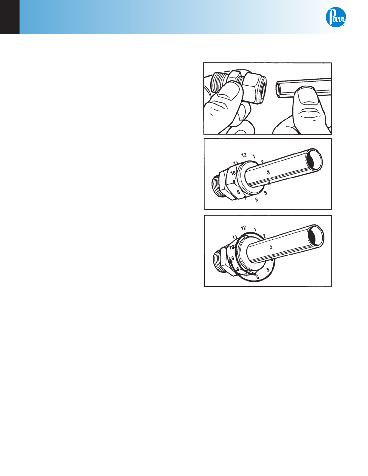
Figure 1-1
Swagelok Tube Fittings
This apparatus is to be used indoors. It requires at
least 4 square feet of workspace on a sturdy bench
or table in a well-ventilated area with convenient
access to an electric outlet, running water and a
drain.
Swagelok Tube Fittings
When Swagelok Tube Fittings are used, the instructions for installation are:
1. Simply insert the tubing into the Swagelok Tube
Fitting. Make sure that the tubing rests firmly
on the shoulder of the fitting and that the nut is
finger-tight.
2. Before tightening the Swagelok nut, scribe the
nut at the 6 o’clock position.
3. While holding the fitting body steady with a
back-up wrench, tighten the nut 1-1/4 turns.
Watch the scribe mark, make one complete revolution and continue to the 9 o’clock position.
4. For 3/16” and 4mm or smaller tube ttings, tight-
en the Swagelok nut 3/4 turns from nger-tight.
Swagelok tubing connections can be disconnected
and retightened many times. The same reliable leakproof seal can be obtained every time the connection is remade using the simple two-step procedure.
1. Insert the tubing with pre-swaged ferrules into
the fitting body until the front ferrule seats.
2. Tighten the nut by hand. Rotate the nut to the
original position with a wrench. An increase in
resistance will be encountered at the original
position. Then tighten slightly with a wrench.
Smaller tube sizes (up to 3/16” or 4mm) take less
tightening to reach the original position than
larger tube sizes.
8
Parr Instrument Company
Page 11

6400
Installation
1
The type of tubing and the wall thickness also has
an effect on the amount of tightening required.
Plastic tubing requires a minimal amount of additional tightening while heavy wall metal tubing
may require somewhat more tightening. In general,
the nut only needs to be tightened about 1/8 turn
beyond finger tight where the ferrule seats in order
to obtain a tight seal.
Over tightening the nut should be avoided. Over
tightening the nut causes distortion (flaring) of the
lip of the tube fitting where the ferrule seats. This
in turn causes the threaded portion of the body to
deform. It becomes difficult to tighten the nut by
hand during a subsequent re-tightening when the
fitting body becomes distorted in this manner.
Required Consumables, Utilities and Power Requirements
The 6400 Calorimeter requires availability of
oxygen, 99.5% purity, with appropriate connection,
2500 psig, maximum.
The 6400 Calorimeter requires availability of nitrogen or air, oil and water free, with appropriate
connection, 2500 psig, maximum.
Electrical Connection
Plug the power line into any grounded outlet providing proper voltage that matches the specification on
the nameplate of the calorimeter. Grounding is very
important not only as a safety measure, but also to
ensure satisfactory controller performance. If there
is any question about the reliability of the ground
connection through the power cord, run a separate
earth ground wire to the controller chassis.
Turn the power switch to the ON position. After
a short time, the Parr logo will appear on the LCD
display followed by a running description of the instrument boot sequence. When the boot sequence
is complete, the Main Menu is displayed.
Front Panel Meter
The panel meter on the front of the calorimeter
controls the temperature of the water in the internal
cooling resorvoir. The setpoint is locked at 15 °C.
A red light will flash in the upper left corner of the
display when the water is being cooled.
Approximately 16L of distilled water are required to
fill the external pressurized rinse tank.
Approximately 2L of distilled, de-ionized, or tap
water, with a total hardness of 85 ppm or less, are
required for filling the internal cooling reservoir.
The power requirements for the sub-assemblies of
the 6400 Calorimeter are:
Calorimeter
5.0 Amps @ 120 VAC
3.0 Amps @ 240 VAC
Printer
(100 to 240 VAC, 50/60 Hz) 0.35 Amps
www.parrinst.com
9
Page 12
1
Installation
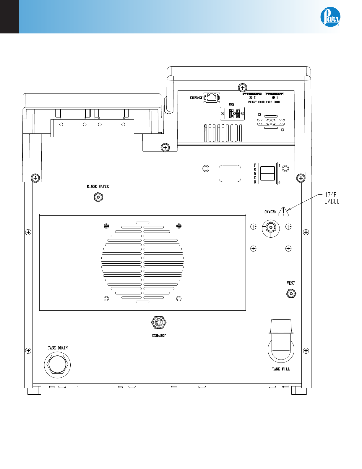
Figure 1-2
6400 Calorimeter Back Panel
10
Parr Instrument Company
Page 13
6400
Water Connection
Installation
1
Remove the cap plug on the water filling elbow and
fill the internal reservoir tank with water having a
total hardness of 85 ppm or less, until the water level
is at the bottom of the filling elbow. The calorimeter
water tank will initially accept about 2 liters.
Fill the external rinse tank with about 16 liters of
distilled water through the large opening at the top
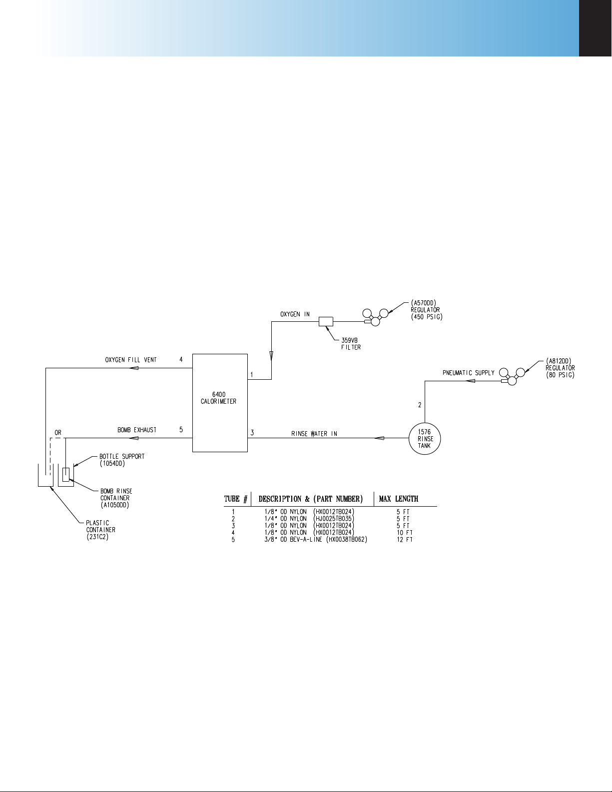
Figure 1-3
6400 External Plumbing
of the tank. The cover for this opening is removed
by lifting up on the handle, pushing down on the lid,
tilting and removing. Replace and close the cover
after filling.
The connection between the calorimeter and the
1576 Rinse Tank should be made with a piece of 1/8”
nylon pressure hose (HX0012TB024). See Figure 1-3.
www.parrinst.com
11
Page 14

1
Installation
Gas Connection
Make the connections to the oxygen supply at this
time. Refer to Figure 1-3. 1/8” O.D. nylon pressure
hose (HX0012TB024) is used to connect the oxygen
supply. The inlet connection incorporates a flow
restrictor just behind the inlet connection. When
making the oxygen connection, a back-up wrench
should be placed on the restrictor to insure a secure
connection and to prevent over tightening the flow
restrictor. The delivery pressure for oxygen should
be set to 450 psig. To install the regulator, unscrew
the protecting cap from the tank and inspect the
threads on the tank outlet to be sure they are clean
and in good condition. Place the ball end of the
regulator in the tank outlet and draw up the union
nut tightly, keeping the gages tilted slightly back
from an upright position. Open the tank valve and
check for leaks. The bomb must never be filled to
more than 600 psig (40 atm).
Make the connections to the nitrogen supply at this
time. 1/4” O.D. nylon pressure hose (HJ0025TB035)
is used to connect the A812DD Nitrogen Regulator
to the 1576 Rinse Tank. When making the nitrogen
connection, a back-up wrench should be placed on
the fitting to insure a secure connection and to prevent over tightening the flow restrictor. The delivery
pressure for nitrogen should be set at 80 psig. To
install the regulator, unscrew the protecting cap
from the tank and inspect the threads on the tank
outlet to be sure they are clean and in good condition. Place the ball end of the regulator in the tank
outlet and draw up the union nut tightly, keeping the
gages tilted slightly back from an upright position.
Open the tank valve and check for leaks.
Note: A hissing sound will occur while the
rinse tank is being pressurized. This is normal. Adjust the pneumatic supply regulator
to 80 psig as needed.
During extended periods of inactivity, close the tank
valve to prevent depleting the tank in the event of
a leak. Close the tank valve prior to removing the
regulator when changing tanks. Do not use oil or
combustible lubricants in connection with any part
of the oxygen filling system. Keep all threads, fittings and gaskets clean and in good condition.
Bomb Exhaust Connections
The exhaust and vent connections at the rear of the
calorimeter, are made with the dual tube A1006DD
assembly. The end of the assembly with the bomb
exhaust diffuser should be placed into the 10 liter
carboy (231C2). The carboy should be placed at or
below the level of the calorimeter to facilitate complete draining of these lines.
Alternatively:
The A1050DD Bomb Rinse Container Assembly is
available as an accessory to the 6400 Calorimeter.
See Figure 14-19. This device allows for complete
and systematic recovery of the bomb combustion
products. These combustion products include the
initial line exhaust after the fill cycle and the portion expelled during the bomb rinse cycle. The
Bomb Rinse Container Assembly is connected to
the rear of the calorimeter, in place of the portion
of the waste tube assembly that is connected to the
bomb exhaust fitting. Combustion products are
discharged from the bomb in two steps. The first
step occurs during the initial rapid release of the
residual bomb gases. The 1053DD bottle has sufficient strength and volume to deal effectively with
this sudden pressure release. Gas is expelled from
the four holes on the perimeter of the 1052DD bottle
cap, leaving any discharged liquid in the bottle. As
an additional safety measure, the bottle is supported
in a 1054DD acrylic cylinder which serves to keep
the bottle upright and contained in the unlikely
event the bottle ruptures. At the end of the bomb
exhaust step the aqueous combustion products
reside in the bomb, associated tubing as well as the
1053DD bottle. The bomb rinse step flushes these
combustion products from the bomb and the tubing
into the 1053DD bottle. The bottle can then be
unscrewed from the assembly and capped, until the
sample is to be analyzed. Some users find it useful
to add the contents of the rinsed combustion capsule to the washings collected in the bottle. Three
1053DD bottles are provided with the assembly.
Additional bottles may be ordered separately from
Parr.
Note: To release the pressure inside the rinse
tank turn off the gas supply and open the gas
relief valve lever. Gas will exhaust through
the relief valve. Once the pressure has equalized remove the lid to refill the rinse tank.
12
Parr Instrument Company
Page 15

6400
Installation
1
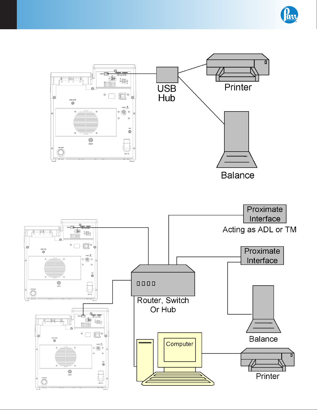
Communication Connections
There is a Universal Serial Buss (USB) port at the
rear of the calorimeter.
The USB port is used to connect to external devices
such as a printer or balance. Multiple devices can be
attached by installing a USB hub.
The 6400 Calorimeter is also equipped with an RJ45
Ethernet port for connection to a computer.
The 6400 will also allow the user to specify the
IP addresses of one or more Balance Interface
devices on the network by selecting the Network
Data Device menu in the Communications Controls
menu. Balance Interface devices are polled from
device 1 to 15 for sample and/or spike weights when
the weight entry mode is set to Network.
Printer Connections
The printer settings are on the Communication
Controls Menu. The default parameters for the 6400
are set up for use with the Parr 1758 Printer.
Mettler 011/012 Interface
The ID field must contain
“S_” to indicate a stable
mass. The data field contains the current mass, right
justified, with a decimal
point. The balance should
be configured to send continuously.
Sartorius Interface
The polarity field must contain either a “+” or a space.
Leading zeros in the data
field are blanked, except
for the one to the left of the
decimal point. The stability
field must contain “g_” for
the calorimeter to accept a
mass. The balance should
be configured to transmit data upon receipt of
the following command string:
[ESC] P [CR] [LF]
Field Length
ID 2
space 1
data 9
space 1
g 1
CR 1
LF 1
Field Length
polarity 1
space 1
data 8
space 1
stability 2
CR 1
LF 1
Balance Connections
The 6400 Calorimeter supports input from multiple
balance types. Additionally, a generic input driver
is provided for communications with balances that
do not conform to the eight supported protocols.
A new feature supported by all balance input drivers is the ability to change the expected number
of characters in the data field. The number of data
characters indicated for each of the drivers, below,
are default values. This feature virtually eliminates
the need for balance input drivers to be re-written
in the event the balance manufacturer elects to alter
the output string of a balance when new models are
introduced.
The format of an unknown balance can be determined by logging the balance output to the printer
attached to the calorimeter. Those protocols which
send a command string to the balance will do so
while logging is active. In order for the logging to
produce meaningful results, the cable connecting
the balance to the balance input port of the calorimeter must be correctly wired or configured. In
addition, the specifics of the data frame, such as the
baud rate, # of data bits, parity, # of stop bits and
handshaking (if used) must be the same for both the
balance and the calorimeter.
Note: The automatic data output option
should not be used.
Generic Interface
The data field should consist of 9 numeric characters
(0 through 9, +, - and space)
terminated with a carriage
return (CR). Leading zeros may be blanked as
spaces and are counted. Non-numeric characters are ignored and will reset the input buffer if
the data field has not been filled. Any characters
received after filling the data field and before the
carriage return are ignored.
Field Length
data 8
CR 1
www.parrinst.com
13
Page 16
1
Installation
Figure 1-4
6400 Calorimeter Peripherals
Figure 1-5
Multiple Alternate Configurations
14
Parr Instrument Company
Page 17

6400
Notes
1
www.parrinst.com
15
Page 18

2
Quick Start
chaPter 2
Quick Start
Initial Fill
When you first fill the calorimeter with water the
main reservoir will be filled. There is also a cooling
water reservoir that is filled from the main reservoir.
Once the calorimeter has been filled with water and
all external connections made:
1. Turn on the calorimeter.
2. Once at the Main Menu go to the Calorimeter Op-
eration screen and turn ON the heater and pump.
Water should start to circulate in the tubing.
3. Press Escape to get back to the Main Menu. Then
press Diagnostics and then I/O Diagnostics.
4. Use the side arrow keys(< >) until the description
reads H2O Cool.
5. Unlock and remove the vessel head.
6. Press “1” to turn on the H2O Cool. You should
hear a click and then gurgling coming from the
bomb cylinder.
7. Once the gurgling stops turn off the H2O cool by
pressing “O”.
8. Refill the main reservoir through the elbow at
the back of the calorimeter.
The above procedure will only need to be done
when the calorimeter is first filled with water after
receiving it.
Quick Start
1. Turn on the heater and pump in the Calorimeter
Operation menu. Allow at least 20 minutes for
the calorimeter to warm up.
2. Initiate a pretest to run the calorimeter through
the ll and cool/rinse cycles. This function is
used to pre-condition the calorimeter if it has
been sitting idle for an extended period of time
(greater than 15 minutes).
3. Prepare and weigh the sample to 0.0001g.
4. Gently tap capsules that contain powdered
samples to compact the material. (Pellets are
easier to handle than loose samples and they
burn slower in the bomb, thereby reducing the
16
Parr Instrument Company
chances for incomplete combustion).
5. Carefully place the capsule into the capsule
holder, attach 10 cm of ignition thread and install
the bomb head in the calorimeter.
6. Close the calorimeter cover making sure that the
latch is engaged.
7. Select determination or standardization as appropriate on the Calorimeter Operation page, by
toggling the OPERATING MODE key. Press the
START Key. The calorimeter will now prompt the
operator for sample ID number, Bomb ID number, sample weight and spike weight in accordance with the instructions set into the operating
controls page.
8. The calorimeter will now take over and conduct
the test. During the time it is establishing the initial equilibrium, it will display PREPERIOD on the
status bar. Just before it res the bomb, it will
sound a series of short beeps to warn the user
to move away from the calorimeter. Once the
bomb has been fired, the status bar will display
POSTPERIOD. The calorimeter will check to make
certain that a temperature rise occurs and will
then look for the final equilibrium conditions to
be met. If it fails to meet either the initial or final
equilibrium conditions, or if it fails to detect a
temperature rise within the allotted time, the test
will terminate and advise the user of the error.
9. At the conclusion of the test, the calorimeter will
signal the user.
10. Open the cover and remove the head. Examine
the interior of the bomb for soot or other evidence of incomplete combustion. If such evidence is found, the test will have to be discarded.
If using the optional A1050DD Rinse Container
Assembly:
1. Titrate the bomb washings with a standard
sodium carbonate solution using methyl orange,
red or purple indicator. A 0.0709N sodium carbonate solution is recommended for this titration to simplify the calculation. This is prepared
by dissolving 3.76 grams of Na2CO3 in the water
and diluting to one liter. NaOH or KOH solutions
of the same normality may be used.
2. Analyze the bomb washings to determine the
sulfur content of the sample if it exceeds 0.1%.
Methods for determining sulfur are discussed in
Analytical Methods for Oxygen Bombs, No. 207M.
Page 19

6400
Notes
2
www.parrinst.com
17
Page 20
3
Operation
chaPter 3
Operation
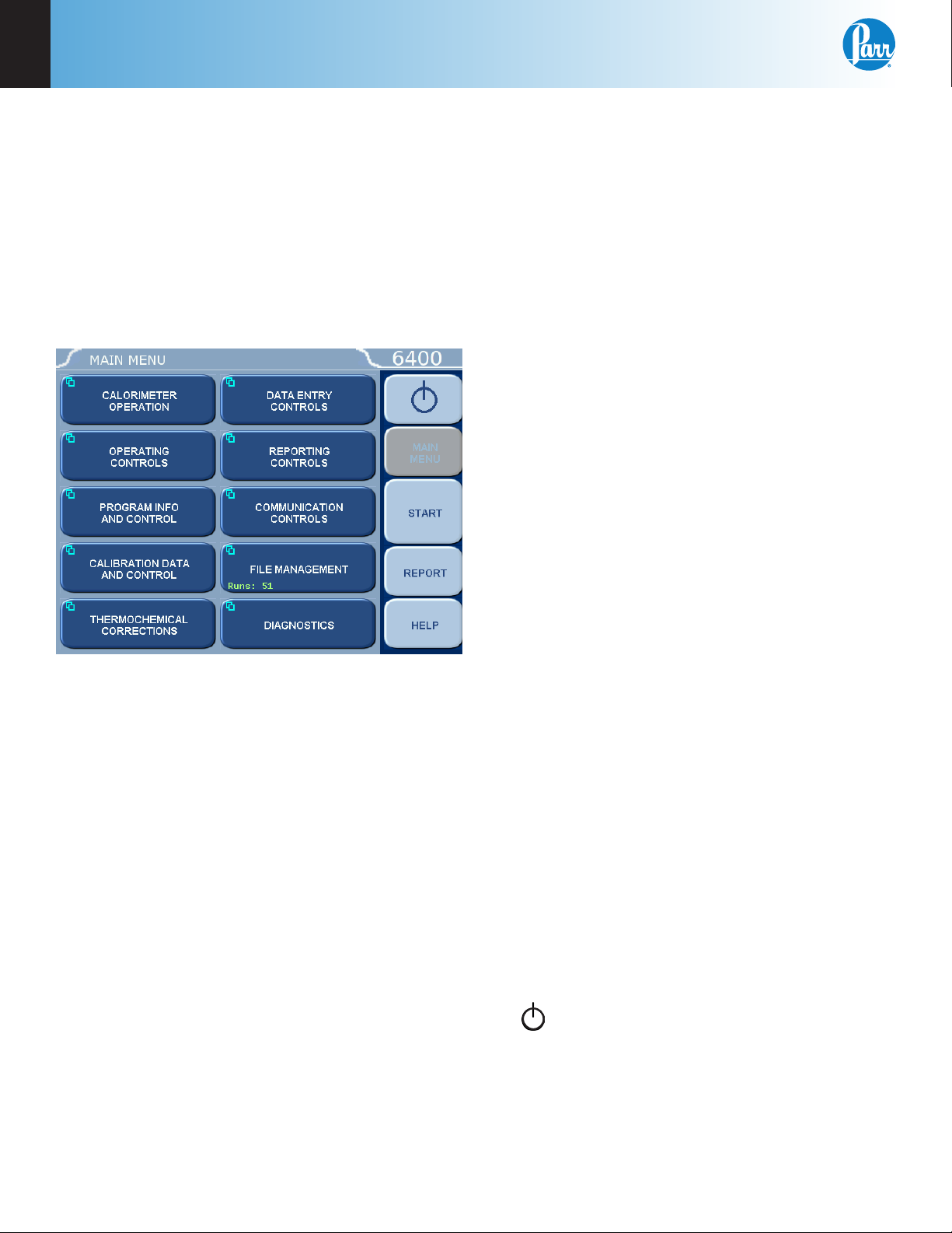
Menu System
All configurations and operations are handled by
a menu-driven system operated from the bright
touch screen display. The settings and controls are
organized into ten main sections as displayed on the
MAIN MENU.
value. Some keys lead to multiple choices.
Always clear the current value before entering a
new value. Once entered the screen will return
to the previous menu and the new value will be
displayed in the lower right corner of the key.
4. Data Displays. Most of these keys display values
that have been calculated by the calorimeter
and are informational only. Certain ones can be
overridden by the user entering a desired value
through a sub-menu. The value is displayed in
the lower right corner of the key.
Note: Some keys will respond with an opportunity for the user to confirm the specified action to minimize accidental disruptions
to the program and/or stored data.
Control Keys
There are five control keys which always appear
in the right column of the primary displays. These
keys are unavailable when they are gray instead of
white.
Note: Keys with a “double box” in the upper
left hand corner lead to sub-menus.
Menu Keys
The controls that change the data field information
in the menus will be one of the following:
1. Toggles. These data elds contain ON/OFF or
YES/NO choices. Simply touching the key on the
screen toggles the choice to the other option.
The current setting is displayed in the lower
right corner of the key.
2. Option Selection. These data fields contain a list
of options. Touching the key on the screen steps
the user through the available choices. The current setting is displayed in the lower right corner
of the key.
3. Value Entry Fields. These data fields are used to
enter data into the Calorimeter. Touching the key
on the screen brings up a sub-menu with a key
pad or similar screen for entering the required
1. Escape. This key is used to go up one level in
the menu structure.
2. Main Menu. This key is used to return to the
main menu touch screen from anywhere in the
menu structure.
3. Start. This key is used to start a test.
4. Abort. When a test is running the Start button
changes to Abort. When pressed it will terminate
the current test or pre-test.
5. Report. This key is used to access the test re-
sults stored in the calorimeter, to enter thermochemical corrections, and to initiate a report on
the display or printer.
6. Help. This key is used to access help screens
related to the menu currently displayed on the
touch screen.
7. This key appears in the Escape key location when the main menu is displayed. This key
is used to shut down the calorimeter program
before turning off the power.
18
Parr Instrument Company
Page 21

6400
Operation
3
Programming
The program in the 6400 Calorimeter can be extensively modified to tailor the unit to a wide variety
of operating conditions, reporting units, laboratory
techniques, available accessories and communication modes. In addition, the calculations, thermochemical corrections and reporting modes can be
modified to conform to a number of standard test
methods and procedures. Numerous provisions are
included to permit the use of other reagent concentrations, techniques, combustion aids and short cuts
appropriate for the user’s work.
Note: Changes to the program are made
by use of the menu structure. Any of these
items can be individually entered at any time
to revise the operating program.
Default Settings
Units are pre programmed with default settings.
See Table 15-1 for a listing of the factory default
settings. A more in-depth explanation of these parameters is found on the corresponding parameter
group help pages. These default settings remain
in effect until changed by the user. Should the user
ever wish to return to the factory default settings, go
to the Program Info and Control Menu, User/Factory
Settings, touch Reload Factory Default Settings and
YES. Non-volatile memory is provided to retain any
and all operator initiated program changes; even
if power is interrupted or the unit is turned off. If
the unit experiences an intentional or unintentional
“Cold Restart”, the controller will return to the last
known settings.
The default parameters of the 6400 Calorimeter can
be changed to guarantee that the calorimeter, when
cold restarted, will always be in the desired configuration before beginning a series of tests. Users who
wish to permanently revise their default settings
may do so using the following procedure:
• Establish the operating parameters to be stored
as the user default settings.
• Go to the Program Info and Control Menu, User/
Factory Settings, User Setup ID, and enter the
desired User Setup ID.
• Select Save User Default Settings
To re-load the user default setting, go to the Pro-
gram Info and Control Page, User/Factory Settings,
Re-load User Default Settings, and YES.
Sample Preparation
Sample Size
To stay within safe limits, the bomb should never be
charged with a sample which will release more than
8000 calories when burned in oxygen. The initial
oxygen pressure is set at 30 atmospheres (450 psig).
This generally limits the mass of the combustible
charge (sample plus benzoic acid, gelatin, firing oil
or any combustion aid) to not more than 1.1 grams.
To avoid damage to the bomb and calorimeter,
and possible injury to the operator, it should be
a standing rule in each laboratory that the bomb
must never be charged with more than 1.5 grams of
combustible material.
When starting tests with new or unfamiliar materials, it is always best to use samples of less than 0.7
grams with the possibility of increasing the amount if
preliminary tests indicate no abnormal behavior and
the sample will not exceed the 8000 calorie limit.
Samples containing sulfur should contain no more
than 50 mg of sulfur and liberate at least 5000
calories.
Samples containing chlorine should be spiked to
insure that sample contains no more than 100 mg of
chlorine and liberates at least 5000 calories
Particle Size and Moisture Content
Solid samples burn best in an oxygen bomb when
reduced to 60 mesh, or smaller, and compressed
into a pellet with a 2811 Parr Pellet Press. Large particles may not burn completely and small particles
are easily swept out of the capsule by turbulent
gases during rapid combustion.
Note: Particle size is important because it
influences the reaction rate. Compression
into a pellet is recommended because the
pressure developed during combustion can
be reduced as much as 40% when compared
to the combustion of the material in the
powder form. In addition to giving controlled
burn rates, the formation of pellets from
sample material keeps the sample in the fuel
capsule during combustion.
Materials, such as coal, burn well in the as-received
or air-dry condition, but do not burn completely dry
samples. A certain amount of moisture is desirable
in order to control the burning rate. Moisture content up to 20% can be tolerated in many cases, but
the optimum moisture is best determined by trial
www.parrinst.com
19
Page 22

3
Operation
combustions. If moisture is to be added to retard
the combustion rate, drop the water directly onto
the loose sample or onto a pellet after the sample
has been weighed. Then let the sample stand to
obtain uniform distribution. Low volatile samples
with high water content, such as urine or blood,
can be burned in an open capsule by absorbing the
liquid on filter paper pulp or by adding a combustion aid, such as ethylene glycol.
Sample Types
Because of the difference in combustion characteristics of the many different materials which
may be burned in an oxygen bomb, it is difficult to
give specific directions which will assure complete
combustions for all samples.
The following fundamental conditions should be
considered when burning samples:
• Some part of the sample must be heated to its
ignition temperature to start the combustion
and, in burning, it must liberate sufficient heat
to support its own combustion regardless of the
chilling effect of the adjacent metal parts.
• The combustion must produce sufficient turbulence within the bomb to bring oxygen into
the fuel cup for burning the last traces of the
sample.
• A loose or powdery condition of the sample
which will permit unburned particles to be
ejected during a violent combustion.
• The use of a sample which contains coarse particles will not burn readily. Coal particles which
are too large to pass a 60 mesh screen may not
burn completely.
• The use of a sample pellet which has been made
too hard or too soft can cause spalling and the
ejection of unburned fragments.
• The bottom of the cup should always be at least
one-half inch above the bottom of the bomb or
above the liquid level in the bomb to prevent
thermal quenching.
• If the moisture, ash and other non combustible
material in the sample totals approximately 20%
or more of the charge, it may be difficult to obtain
complete combustion. This condition can be remedied by adding a small amount of benzoic acid or
other combustion aid.
Foodstuffs and Cellulosic Materials
Fibrous and fluffy materials generally require one of
three modes for controlling the burn rate. Fibrous
materials do not pelletize readily and generally
require either moisture content or a combustion aid
such as mineral oil to retard the burn rate and avoid
development of high pressures. Partial drying may
be necessary if the moisture content is too high to
obtain ignition, but if the sample is heat sensitive
and cannot be dried, a water soluble combustion aid
such as ethylene glycol can be added to promote
ignition. Material such as Napthalene should not be
burned in loose powder form but should be formed
into a pellet.
Coarse Samples
In most cases it may be necessary to burn coarse
samples without size reduction since grinding or
drying may introduce unwanted changes. There
is no objection to this if the coarse sample will
ignite and burn completely. Whole wheat grains
and coarse charcoal chunks are typical of materials
which will burn satisfactorily without grinding and
without additives or a special procedure.
Corrosive Samples
The 1138 bomb is made from alloy 20; a special
niobium stabilized stainless steel selected for its
resistance to the mixed nitric and sulfuric acids produced during the combustion process. The 1138CL
is made from the halogen resistant Hastelloy G30™.
Hastelloy 30™ is an alloy rich in cobalt and molybdenum and is able to resist the corrosive effects
of free chlorine and halogen acids produced when
burning samples with significant chlorine content.
While no alloy will completely resist the corrosive
atmospheres produced when burning samples
containing halogen compounds; users who intend
to test these materials are urged to select the 1138CL
Bomb. These bombs are 250 mL in volume and are
rated to a maximum working pressure of 2000 psi.
The bombs are hydrostatically tested to 3000 psi
and the sample range is ~1g or 5000 – 8000 calories.
Explosives and High Energy Fuels
Materials which release large volumes of gas
which detonate with explosive force or burn with
unusually high energy levels, should not be tested
in this calorimeter. Rather, they should be tested
in a model 6100 or 6200 Calorimeter which can be
equipped with an 1104 High Strength Oxygen Bomb
designed specifically for these types of samples.
20
Parr Instrument Company
Page 23
6400
Operation
3
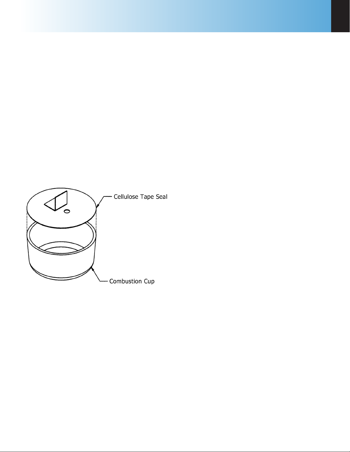
Volatile Sample Holders
Volatile samples are defined as one with an initial
boiling point below 180 ºC. Volatile samples can be
handled in a Parr 43AS Alloy Capsule which has a
sturdy wall with a flat top rim. These holders can be
sealed with a disc of plastic adhesive tape prepared
by stretching tape across the top of the cup and
trimming the excess with a sharp knife. The seal
obtained after pressing this disc firmly against the
rim of the cup with a flat blade will be adequate
for most volatile samples. The tape used for this
purpose should be free of chlorine and as low in
sulfur as possible. Borden Mystic Tape, No. M-169-C
or 3M Transparent Tape, No. 610, are recommended
for this purpose. The 3M Transparent Tape can be
ordered through Parr, Part No. 517A.
Figure 3-1
Volatile Sample Technique
Use the following procedure when filling and handling any of these tape-sealed sample holders:
1. Weigh the empty cup or capsule; then cover the
top with tape, trim with a knife and press the
trimmed edge firmly against the metal rim. Also
cut and attach a small flag to the disc (see Figure
3-1).
2. Puncture the tape at a point below the flag, then
re-weigh the empty cup with its tape cover.
3. Add the sample with a hypodermic syringe;
close the opening with the flag and re-weigh the
filled cup.
4. Set the cup in the capsule holder and arrange
the auxiliary fuse so that it touches the center of
the tape disc.
5. Just before starting the test, prick the disc with
a sharp needle to make a small opening which
is needed to prevent collapse of the disc when
pressure is applied.
The weight of the tape disc must be determined
separately and a correction applied for any elements
in the tape which might interfere with the determination. The approximate Heat of Combustion of
the tape is 6300 cal/g. An actual amount should be
determined by running a blank test with tape alone
using a sample weighing 1.0 gram. The compensation for heat of tape may be done through the spike
option; see Spike Controls, Heat of Combustion of
Spike.
Note: Tape should always be stored in a
sealed container to minimize changes in its
moisture and solvent content.
6. Fill the bomb with the usual oxygen charging
pressure.
7. The calorimeter will fire the bomb and complete
the test in the usual manner.
Combustion Aids
Some samples may be difficult to ignite or they may
burn so slowly that the particles become chilled
below the ignition point before complete combustion is obtained. In such cases white oil or other
suitable material of known purity can be mixed with
the sample. Ethylene glycol, butyl alcohol or decalin
may be used for this purpose.
Note: It must be remembered, that a combustion aid adds to the total energy released
in the bomb and the amount of sample may
have to be reduced to compensate for the
added charge.
When benzoic acid is combusted for standardization
runs, it should be in the form of a pellet to avoid
possible damage to the bomb which might result
from rapid combustion of the loose powder.
www.parrinst.com
21
Page 24

3
Operation
Combustion Capsules
Non-volatile samples to be tested in Parr oxygen
bombs are weighed and burned in shallow capsules
measuring approximately 1” diameter and 7/16”
deep. These are available in stainless steel, fused
silica, fused quartz, and platinum alloyed with
3-1/2% rhodium.
Stainless steel capsules (43AS) are furnished with
each calorimeter. The stainless steel capsules will
acquire a dull gray finish after repeated use in an
oxygen bomb due to the formation of a hard, protective oxide film. This dull finish not only protects the
capsule, but it also promotes combustion and makes
it easier to burn the last traces of the sample. New
capsules are heated in a muffle furnace at 500 ºC for
24 hours to develop this protective coating uniformly on all surfaces. This treatment should be repeated
after a capsule has been polished with an abrasive to
remove any ash or other surface deposits. Heating in
a muffle is also a good way to destroy any traces of
carbon or combustible matter which might remain
in the capsule from a previous test. Capsules should
be monitored for wear. Do not use the capsule if the
wall or base thickness is less than 0.025”.
Note: After heating, place the capsules in
a clean container and handle them only
with forceps when they are removed to be
weighed on an analytical balance.
When combusting samples that contain metal
particles such as aluminum or magnesium, the nonmetallic 43A3 Fused Silica or 43A3KQ Fused Quartz
Capsule is required.
When superior corrosion resistance is needed, the
43A5 Platinum Rhodium Capsule or 43A3KQ Fused
Quartz is required.
Test Process
Loading the sample
Prepare and weigh the sample to 0.0001g. Gently
tap capsules that contain powdered samples to
compact the material. (Pellets are easier to handle
than loose samples and they burn slower in the
bomb, thereby reducing the chances for incomplete
combustion).
Carefully place the
capsule into the capsule
holder. A cotton thread
(845DD2) is used as an
auxiliary fuse to ignite
the sample. Remove any
moisture from the heating wire prior to attaching the cotton thread.
Four inches (10 cm) of
thread is recommended
for this auxiliary thread
which is looped over the
heating wire, doubled
on itself, twisted to form
a single strand and fed
into the sample cup to
lay on the sample. When
contact is made through
the heating wire, the
thread will ignite, drop into the sample cup and
ignite the sample. One spool of thread, part number
845DD, is 563 yards. Part number 845DD2 contains
approximately 1000 pieces of thread pre-cut to 4
inches (10 cm).
Closing the bomb
Care must be taken not to disturb the sample when
moving the bomb head from the support stand to
the bomb cylinder in the calorimeter. Check the
sealing ring to be sure that it is in good condition
and moisten it with a bit of water so that it will slide
freely into the cylinder.
Notice that the bomb head grounding lug extends
beyond the outside diameter of the bomb head. A
slot for this lug is cut into the top of the calorimeter
bucket which holds the bomb cylinder. Position
this lug approximately 20 degrees to the operators
right and slide the head into the cylinder and push it
down as far as it will go. Now rotate the bomb head
20 degrees to the left until the lug contacts the left
edge of the cut out and is pointed to the front of the
calorimeter.
Cotton Thread Assembly
Figure 3-2
22
Parr Instrument Company
Page 25
6400
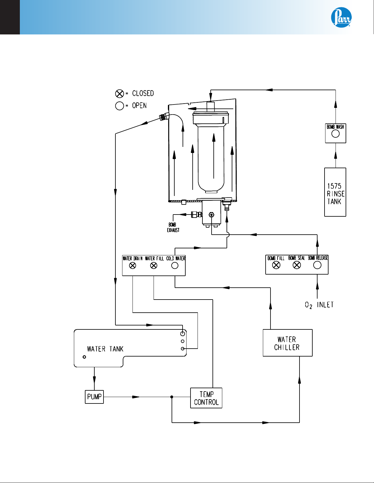
Fill Cycle
Once the calorimeter is started and the cover is closed, the fill sequence begins.
Figure 3-3
Bucket Fill Flow Diagram
Operation
3
1. The calorimeter checks the bomb ignition circuitry for continuity.
2. The water fill solenoid opens and water is pumped from the internal tank into and through the bucket that
surrounds the bomb. Overflow from the bucket is returned to the closed water tank. Because the jacket and
bucket are both filled with water from the closed water tank, initial equilibrium will be reached quickly.
3. The oxygen fill solenoid is opened and oxygen is added slowly to the bomb to bring its pressure to
approximately 30 atm.
www.parrinst.com
23
Page 26
3
Operation
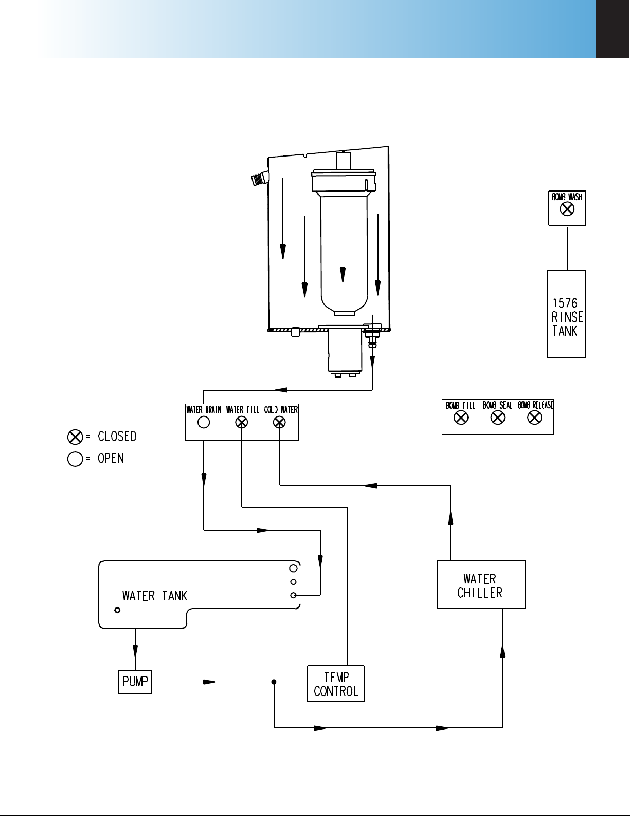
Pre-Period
At the completion of the fill sequence, the pre-period begins.
Figure 3-4
Pre-Period/Post-Period Flow Diagram
1. The water fill solenoid valve closes and isolates the water in the bucket from the rest of the system.
Water within this bucket is circulated by the stirrer. Water continues to circulate from the closed water
system through the jacket surrounding the bucket.
2. The oxygen filling valve closes and the pressure in the filling line is vented. The automatic check valve at
the top of the bomb closes and isolates the bomb from the oxygen filling line.
3. The controller monitors the operating temperature until it confirms that the initial equilibrium has been
established.
24
Parr Instrument Company
Page 27

6400
Operation
3
Bomb Firing
Once the initial equilibrium is confirmed, the controller initiates the firing sequence. There are no
changes to the circulation pattern, as shown in
Figure 3-4, from the pre-period through the bomb
firing and post-period. A warning of short beeps is
sounded indicating the bomb is about to be fired.
Post-Period
A minimal temperature rise will confirm that the
sample has ignited. After this verification, the postperiod begins. See Figure 3-4.
1. The controller monitors the temperature rise
and determines the final temperature rise by
either the dynamic or equilibrium criteria as
established by the user.
2. Once the final temperature rise is determined,
it is recorded with the test results.
www.parrinst.com
25
Page 28
3
Operation
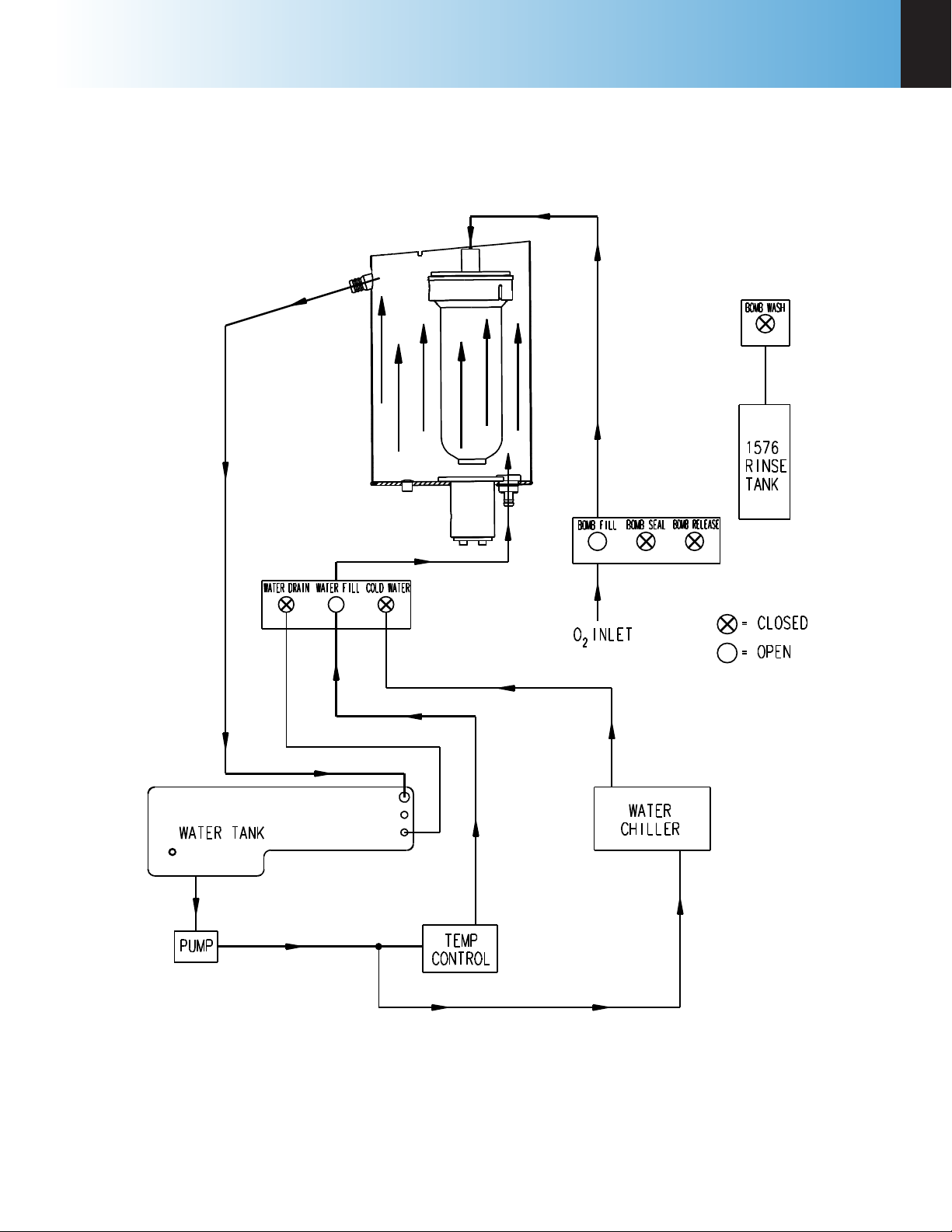
Cool/Rinse
At the completion of the post-period, the rinse and cool sequence begins.
Figure 3-5
Rinse & Cool Flow Diagram
1. Chilled water is circulated through the bucket
to cool the bomb to the
starting temperature.
2. The release valve in the
bottom of the bomb is
opened and the residual
pressure is released
through the bomb exhaust line.
3. Once the excess oxygen
is vented, the bomb rinse
water from the rinse
water tank is admitted
through the bomb rinse
solenoid valve and the
check valve at the top
of the bomb. The bomb
rinse water is released to
the wash bottle.
Note: Several rinse
patterns may be configured by the user to
meet various operational and analytical
requirements.
4. The bomb is filled one
more time with oxygen
to help flush
the water
residue
from the
interior of
the bomb.
26
Parr Instrument Company
Page 29
6400
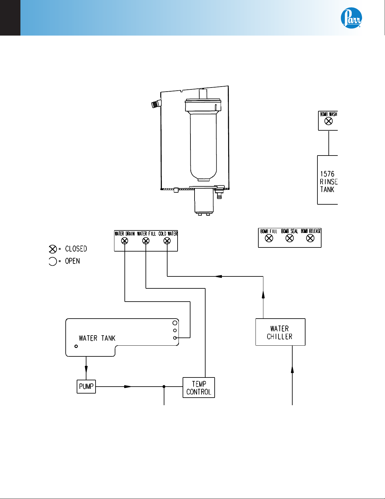
Drain
At the completion of the bomb rinse sequence, the drain sequence begins.
Figure 3-6
Drain Flow Diagram
Operation
3
The water in the bucket is drained out of the bucket and routed to the drain connection. Once the bucket is
drained, the calorimeter may be opened to remove the bomb head and load the next sample.
www.parrinst.com
27
Page 30
4
Menu Descriptions
chaPter 4
Menu Descriptions
Note: Keys which make global changes to
the setup of the calorimeter contain a YES or
NO response to make certain that the user
wishes to proceed. This two step entry is
intended to prevent inadvertent global program changes.
Main Menu
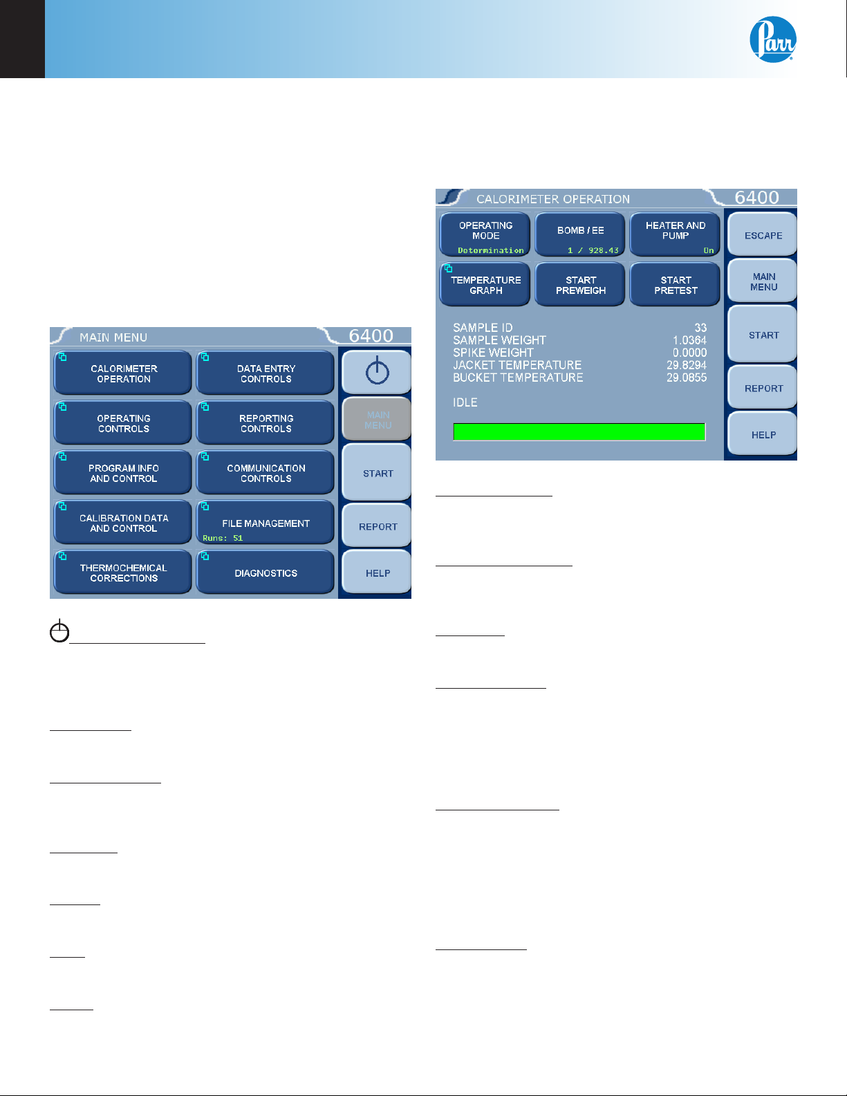
Calorimeter Operation Menu
The Calorimeter will normally be operated from the
Calorimeter Operation Menu, although tests can
always be started from any menu screen.
System Shutdown: This key appears in the
ESCAPE key location when the Main Menu is displayed. Pressing this button will prompt the user to
confirm a system shutdown.
Escape Key: Selecting the Escape key on any menu
will return you to the menu one level up.
Main Menu Key: Selecting the Main Menu key on
any menu will return you to the screen pictured on
the right of this page.
Start Key: Press the Start key to begin any Determination or Standardization run.
Report: Press the Report key to begin the reporting
process.
Operating Mode: Sets the operating mode by
toggling between Standardization (for instrument
calibration) and Determination (for test runs).
Temperature Graph: Press this key to display a real-
time plot of the bucket and/or jacket temperature on
the Temperature vs. Time Plot screen.
Bomb/EE: Used to identify the bomb presently
installed in the Calorimeter and its EE value.
Start Preweigh: This key is used to start the sample
pre-weigh process. The user is presented with or
prompted for a sample ID. Next, the user is asked to
key in the associated sample mass or alternatively
the mass is retrieved from a connected balance or
network.
Heater and Pump: The heater and pump must only
be turned on after the calorimeter water tank is filled
with water.
Note: The heater and pump must be turned
ON to bring the jacket to the correct starting
temperature before testing can commence.
Help: Press the Help key on any screen to display
the explanation text for that screen.
Abort: This key appears in the Start key location
while a test or pretest is running. Pressing this key
will abort the test or pretest in progress.
28
Parr Instrument Company
Start Pretest: This key is used to initiate a pretest
cycle. A pretest will cycle the calorimeter through
the ll and cool/rinse process. This function is used
to pre-condition the calorimeter.
Page 31

6400
Menu Descriptions
4
Temperature vs. Time Plot
Setup: Press the Setup key to access the Temperature Plot Setup Menu, which has many
keys that permit the user to fully customize
both the x (time) axis and the scaling of the y
axis.
Temperature Plot Setup Menu
Bucket Plot Symbol: Toggles between -
» No Point
» Small Dot
» Round
» Square
» Up Triangle
» Down Triangle
» Diamond
Bucket Min Value: Press this key to access its
numeric dialog box to set a minimum bucket
value.
Jacket Plot Symbol: Toggles between (same as
Bucket Plot Symbol, above).
Jacket Min Value: Press this key to access its
numeric dialog box to set a minimum jacket
value.
Time Window: Sets the time scale for the Xaxis.
Time Units: Toggles between minutes and
seconds.
Enable Bucket: Toggles ON/OFF.
Bucket Autoscale: Toggles ON/OFF.
Enable Jacket: Toggles ON/OFF.
Jacket Autoscale: Toggles ON/OFF.
Time Mode: Toggles between Autoscale, Win-
dow, and Range.
Bucket Plot Color: Toggles between -
» Red
» Green
» Yellow
» Blue
» Magenta
» Cyan
» White
» Black
Bucket Max Value: Press this key to access its
numeric dialog box to set a maximum bucket
value.
Jacket Plot Color: Toggles between: (same as
Bucket Plot Color, above).
Jacket Max Value: Press this key to access its
numeric dialog box to set a maximum jacket
value.
Time Minimum: Press this key to access its
numeric dialog box to set the least amount of
time for the display.
Time Maximum: Press this key to access its
numeric dialog box to set the greatest amount
of time for the display.
www.parrinst.com
29
Page 32

4
Menu Descriptions
Operating Controls Menu
Method of Operation: Offers an operating mode of
either dynamic or equilibrium. In most cases, the
dynamic mode with its curve matching capability
will save approximately 3-4 minutes per test and will
produce the same operating precision as the slower
equilibrium mode.
Reporting Units: Offers a choice of BYU/lb, cal/g,
J/kg, or MJ/kg for the reporting units. A user
selected set of reporting units may be chosen by
selecting “other”.
Spiking Correction: Accesses the Spike Controls
sub-menu. “Spiking” is the addition of material,
such as benzoic acid or mineral oil, to samples
which are difficult to burn in order to drive the
combustion to completion.
Spiking Controls
Use Spiking: When set to ON, the calorimeter
will prompt for the weight of the spike added
and will compensate for the heat of combustion in the calculations.
Heat of Combustion of Spike: The heat of
combustion of spike is entered on sub-menu
keyboard in cal/g.
Use Fixed Spike: When set to ON, a constant
amount of spike is to be added to each test.
Weight of Fixed Spike: The weight of the fixed
spike is entered on sub-menu keyboard.
Note: The precision of tests with fixed spikes
can be no better than the accuracy of the
spike weight.
30
Prompt for Spike before Weight: When set to
ON, the calorimeter will prompt the user for
the weight of the spike and then the weight
of the sample. Normally the calorimeter will
prompt the user for the weight of the sample
and then the weight of the spike.
Bomb Rinse Tank Controls: Accesses the Rinse Tank
Controls sub-menu. Wash water for the bomb is
drawn from the Bomb Rinse Tank
Parr Instrument Company
Page 33

6400
Menu Descriptions
4
Bomb Rinse Tank Controls
Report Rinse Tank Empty: When turned on
the calorimeter will notify the user when it
believes the rinse tank is empty based upon
capacity of tank and number of tests.
Rinse Tank Capacity: Sets the number of tests
available from a full container. If the rinse
timing controls have been changed, then the
value must be changed proportionally.
# Rinses Left: This value provides an estimate
of how many rinses are left in the tank. This
number is simply a counter not an actual measurement of the volume in the tank.
Rinse Flush Time: This value is used to establish a time between rinse cycles. During this
time the rinse solenoid is turned OFF. This
off time permits the rinse water to drain out
before the next rinse cycle begins. The factory
default value is 2s.
Clear Time: This time value is used to establish
a post-rinse oxygen filling time for the bomb.
This step is used to clear the lines and valves
of any residual rinse water prior to the next
test. The factory default value is 10s.
# of Rinse Cycles: This value establishes the
number of distinct rinse cycles used to rinse the
bomb. The factory default value is 3 rinse cycles
Note: Rinse Time, Rinse Flush Time, and
Clear Time are input in tenths of a second in
order to enable fine tuning of rinse function.
“Other” Multiplier: Press this key to display the
Other Multiplier dialog box, where the user can
enter a final multiplier to be used when the reporting units are set to “Other”.
Calibrate Touchscreen: This key prompts the user
to touch the screen at predefined points in order to
facilitate touch screen calibration. It is important that
a touch screen stylus, rather than a finger, be used
in order to realize an accurate calibration.
Reset Rinse Tank Counter: Resets the counter
when the rinse tank has been refilled. This
counter must be reset after the rinse tank is
refilled.
Rinse Time: This value establishes the time
that the rinse water solenoid is turned ON for
each rinse cycle. When the rinse water solenoid is ON, distilled water from the rinse tank
is pumped, under pressure, into the bomb
cylinder. This rinses the cylinder walls and the
bomb head. These rinsings are then pooled
and collected at the exhaust port of the calorimeter. The factory default value is 2.5s. This
value, along with the # of rinse cycles, determines the total volume of recovered rinse.
These default values will yield a total of 50 mL
(approx.) of bomb washings.
LCD Backlight Timeout: The unit is equipped with
an automatic circuit to shut off the backlight when it
is not being used. The back light will shut off if there
is no keyboard activity for the number of seconds
entered. Pressing any key will automatically turn
the back lighting ON. A setting of 0 will keep the
backlight ON at all times.
LCD Backlight Intensity: This key accesses a submenu with a slide control which adjusts the brightness on the LCD display for optimum viewing.
Print Error Messages: When turned ON, all error
messages will be printed on the printer as well as
displayed on the screen. When turned OFF, messages will only display on the screen.
Language: Steps the Calorimeter through the
installed operating languages.
www.parrinst.com
31
Page 34

4
Menu Descriptions
Program Information and Control Menu
Date & Time: Accesses a sub-menu to set the current date and time.
Date: Displays current date and accesses
sub-menu on which date is set in (YY/MM/DD)
format.
Time: Displays current time and accesses submenu on which time is set in (HH:MM) format.
Time Zone: Displays the selected time zone
in relation to Greenwich Mean Time. Pressing
this key will step through the time zones and
automatically adjust the time setting.
Volume Level Adjust: Opens a window with a slide
adjustment to set the volume of the key cliks and
alarms of the calorimeter. Default is 85%.
Software and Hardware Info: This screen displays
important information such as the main software
version, I/O board information, CPU information,
and IP address assigned.
Software & Hardware Info
Settings Protect: Provides protection for the
program options and settings on the menus. If
this is turned ON, the user will be warned that
enumeration keys are locked when a key is pressed.
Enumeration Keys either toggle a value (ON/OFF)
or select from a predefined list. This feature is used
primarily to protect the instrument settings from accidental changes if one were to inadvertently touch
or bump up against the touchscreen.
32
Parr Instrument Company
Page 35

6400
Menu Descriptions
4
User/Factory Settings: This key leads to a submenu that allows the user to save or recall user
defined instrument settings. Additionally, factory
pre installed settings supporting different bombs or
special operating modes can also be recalled.
User/Factory Settings
User Setup ID: Used to enter a unique identifier for recalling user settings. Parr offers a
unique program within the 6400 identified as
“64-FAST”. The program will “overlay” the
factory settings and shorten the run time by
approximately 2 minutes however the user
should be aware that a loss of precision may
occur.
Reload Factory Default Settings: Used to erase
all of the settings and restore the factory default settings.
Reload User Default Settings: Used to restore
the user setup ID settings should the program
in the instrument be corrupted for any reason.
Save User Default Settings: Used to record the
setup to the memory once the user has configured the instrument to their operating requirements.
Compare Settings With Factory Defaults: This
button will bring up a screen that will show the
differences in the current settings of the calorimeter with the factory defaults.
Feature Key: This key displays a screen which
allows the user to input a code to access special
calorimeter features such as the bar code capabilities, remote calorimeter operation or Samba server
feature.
Bomb Type Select: This key toggles through the
different bomb models available for the calorimeter.
When the user chooses a bomb, the instrument
must be re-booted to load the correct version of the
software. (Note that the calorimeter will not let you
exit this function without re-booting the system).
Currently, there is only one bomb selection for the
6400.
User Function Setup: This key leads to sub-menus
that support the conguration of ve factory/user
definable function keys. The function keys are accessible from the Diagnostics page.
Cold Restart: This is essentially the same as cycling
power on the unit. All valid test data will be retained during this cold restart procedure.
www.parrinst.com
33
Page 36

4
Menu Descriptions
Calibration Data and Controls Menu
Calibration Run Limit: Displays the maximum
number of runs that will be included in determining
the EE value of a bomb and bucket combination and
accesses the sub-menu on which this limit is set.
Most test methods suggest 10 tests. Tests in excess
of the most recent ones used are still available but
are not used in the calculation of the EE value. For
example if 11 standardization tests have been run,
the calorimeter will only use the most recent 10. The
11th is still stored in the memory and is available
for viewing or printing. Only runs that are at final
status will be used in this calculation.
EE Max Std Deviation: Displays the maximum
relative standard deviation in percent that will be
permitted for any EE value calculated by the Calorimeter and accesses the sub-menu on which this
limit is set. If this value is exceeded, the user will be
warned to take corrective action before proceeding
with testing. A setting of zero disables this check.
Heat of Combustion of Standard: Displays the heat
of combustion in calories per gram for the material
used to standardize the calorimeter and accesses
the sub-menu on which this value is set. For benzoic
acid, this value is 6318.4 calories per gram.
Control Chart Parameters: A control chart is a
graphical tool which can assist the user in determining whether or not their process is in control.
Many standard methods will dictate that a reference
sample be measured periodically and the results
plotted on a graph. Limits for acceptable values are
defined and the process is assumed to be in control
as long as the results stay within these limits. Since
results are expected to scatter with a normal distribution within established limits, systematic trends
or patterns in the data plots may also be an early
warning of problems.
Charted Value: Toggles the charted value between
the HOC Standard (Heat Of Combustion of Standard) and Energy Equivalent.
Process Sigma: In relation to calorimetry, sigma
is used as the classification of the instrument. The
higher the process sigma the higher the limits for
acceptable values for precision control.
Note: The 6400 is a .1 Process Sigma calorimeter.
Temp. Rise High Warning: Sets a limit for the temperature rise during a test. If the temperature rise
exceeds the limit the user will be warned.
Temp. Rise Low Warning: Sets a lower limit warning
for the temperature rise during a test. If the temperature rise is lower than this setting the user will
be warned.
Use Bomb: Displays the ID of the bomb currently
being used in the Calorimeter and toggles through
the four possible bomb numbers.
Bomb 1 - Bomb 4: Leads to sub-menu, Bomb 1 Bobm 4. Displays standardization information for
bomb and bucket combinations. While only one
bomb and bucket is installed in the calorimeter at
a time, a spare may be used for servicing and for
more rapid turn-around. The respective EE values
for each bomb can be stored in memory.
Bomb Service Interval: Displays the maximum
number of times a bomb may be fired before it is
flagged as due for service and accesses the submenu on which this limit is set. Parr recommends
500 firings for this service interval. (Parts may need
to be replaced on a more frequent basis depending
upon the nature of the sample).
34
Parr Instrument Company
Note: For rapid turn around between tests,
the user may wish to use an extra head.
Each head should be assigned a bomb ID.
On the Data Entry Controls Menu, set the
Prompt for Bomb ID to “ON”.
Page 37

6400
Menu Descriptions
4
Bomb 1
The following four values are displayed for the
Bomb # shown in the title on top of the screen.
» Bomb EE Value: Displays the calculated EE value.
» # Runs, EE Val.: Displays how many runs have
been used to determine the EE value.
» Rel. Std. Dev.: Displays the relative standard de-
viation for the series of tests used to determine
the current EE value in percent of the EE value.
» Bomb Fire Count: Displays the current bomb
firing count or the number of times the bomb
has been fired since it was last serviced. When
this count matches the limit set by Bomb Service
Interval (on the Calibration Data and Controls
screen), the user will be informed that the bomb
is ready for service.
Manual EE Entry: This key allows the user to
manually enter an EE or calibration factor for
a given calorimeter ID or bomb head. If an EE
value is manually entered, it is necessary to
turn the Protect EE Value ON in order to prevent this value from being overwritten by an
automatic update.
Print Standardization Runs: This key will print
all of the tests that have been incorporated
into the calculated EE value. This will be helpful in evaluating a series of tests which fail to
produce a satisfactory EE value and relative
standard deviation.
Reset Bomb Fire Count: After bomb service,
press this key to reset the fire count to zero.
Control Chart Plot: Displays the current standardization runs being used to calculate the
Bomb EE Value. The display will either chart
the value of the Heat of Combustion (HOC) of
the Standard or the Energy Equivalent (EE) depending on the selection on the Control Chart
Parameters menu (see Calibration Data and
Controls menu).
Control Plot Chart Plot
You can display the information used for each test
by selecting the appropriate dot.
Name: Enables the operator to assign a
unique alpha-numeric label for the bomb ID.
The ID can be up to 8 characters.
Protect EE Value: Toggles between OFF and
ON. When set to OFF, the 6400 automatically
updates the EE value as new tests are run.
When set to ON, it keeps the EE value protected, whether it has been revised manually via
the Manual EE Entry key or calculated by the
instrument.
Update Statistics: If the Protect EE Value is
set to OFF, pressing this key will cause the EE
Value for this Calorimeter to be updated using
all standardization runs currently in memory
to the limit established in the Calibration Data
and Controls menu. If the Protect EE value is
set to ON, this key is not functional.
Each data point represents a Standardization run
used in the calculation of the EE Value for the Bomb
ID being displayed. The left side of the graph contains the oldest runs and the right represents the
most recent. To view the run data used for a particular data point, click on the data point with a stylus
and the run data for that point is displayed.
www.parrinst.com
35
Page 38

4
Menu Descriptions
Thermochemical Corrections Menu
The Thermochemical Corrections Menu permits
three types of fixed corrections for standardization
(instrument calibration) runs, and the same three
types for determination (test) runs. Pressing the
LEFT side of each key toggles the correction ON or
OFF. Press the RIGHT side of each key to access the
specific numeric dialog box where that fixed value
can be set. Each value entered for these fixed corrections is used in all preliminary reports.
When any fixed correction is set to ON, the specified
value will be used in the final reports, and the 6400
will not prompt for actual corrections to be entered.
(If all corrections are fixed, only a final report will be
generated).
When any fixed correction is set to OFF, during the
data entry reporting steps the user will be prompted
to enter an appropriate desired value which will be
used in the final report.
Further information on the corrections is
located in Chapter 7: Calculations.
Standardization Corrections
Fixed Fuse Correction: Press this key on the LEFT
side to toggle ON or OFF the fixed fuse correction
for standardization runs. Press it on the RIGHT side
to access the Fixed Fuse numeric dialog box on
which the value can be set. An appropriate fixed
fuse value is 50 calories.
Acid Correction: Press this key on the LEFT side
to toggle between Fixed HNO3, Calculated HNO3
, Entered Total, Entered HNO3, and Fixed Total for
the acid correction for standardization runs. Press
it on the RIGHT side to access the Acid Correction
numeric dialog box on which the value can be set.
An appropriate Fixed HNO3 value is 8 calories when
one-gram benzoic acid pellets are used to calibrate
the instrument.
Fixed Sulfur Correction: Press this key on the LEFT
side to toggle ON or OFF the fixed sulfur correction
for standardization runs. Press it on the RIGHT side
to access the Fixed Sulfur numeric dialog box on
which the value can be set. When benzoic acid is
used as the calibrant, a fixed sulfur value of zero
should be used.
Determination Corrections
Fixed Fuse Correction: Press this key on the LEFT
side to toggle ON or OFF the fixed fuse correction
for determination runs. Press it on the RIGHT side
to access the Fixed Fuse numeric dialog box on
which the value can be set. An appropriate fixed
fuse value is 50 calories.
Acid Correction: Press this key on the LEFT side
to toggle between Fixed HNO3, Calculated HNO3 ,
Entered Total, Entered HNO3, and Fixed Total for the
acid correction for determination runs. Press it on
the RIGHT side to access the Acid Correction numeric dialog box on which the value can be set.
Fixed Sulfur Correction: Press this key on the LEFT
side to toggle ON or OFF the fixed sulfur correction
for determination runs. Press it on the RIGHT side
to access the Fixed Sulfur numeric dialog box on
which the value can be set.
Note: When fixed corrections are turned ON,
the value in the specified field will be used
in both the preliminary and final reports.
The calorimeter will not prompt for actual
corrections. If all corrections are fixed, only
final reports will be generated. If any correction value is entered and the toggle is set to
OFF, then the preliminary report will use the
displayed fixed value, but the final report will
use the value entered when prompted during
the reporting process.
36
Parr Instrument Company
Page 39

6400
Menu Descriptions
4
Calculation Factors: Accesses the Calculation Factors sub-menu, which provides for setting a number
of options for the way the thermochemical corrections are applied.
Calculation Factors Menu
Nitric Acid Factor: The default is 1.58 calories
per 1000 calories of released energy.
Acid Multiplier: This multiplier is the normality
of the sodium carbonate used during the acid
correction titration. The default value of 0.0709
allows for direct entry of the acid correction
in calories. If the bomb rinses are titrated in
order to determine the acid correction, press
this key to display the Acid Multiplier numeric
dialog box, where you can change the multiplier to represent the concentration of the base
(equivalents/L) or normality used for titration.
If this is the case, the acid correction is entered
as milliliters of base used to titrate the bomb
rinses.
Sulfur Value is Percent: When set to ON, the
sulfur value is being entered as weight percent
sulfur. If another system is to be used, this
must be turned OFF and the sulfur multiplier
set accordingly.
Sulfur Multiplier: Values entered by the user to
be used for the sulfur correction are multiplied
by this value to get the product into units of
milliequivalents. The default number (0.6238)
requires that the sulfur value be entered in
weight percent.
Fuse Multiplier: The fuse corrections represent the number of calories liberated by the
burning fuse wire used to ignite the sample. If
another measurement is used, the correction
factor must be entered here. Press this key to
access the Fuse Multiplier numeric dialog box
and enter this multiplier value.
Use Offset Correction (ISO): The thermochemical calculations used for treatment of nitric
acid and sulfuric acid corrections in the ISO
and B. S. methods require an offset correction to compensate for the back titration that
is made. To use these calculations, toggle this
to ON and enter the appropriate value as the
offset value.
Offset Value: The value used when Offset
Correction is turned ON. Press this key to access the Offset Value numeric dialog box and
change its value.
Heat of Formation Sulfuric Acid: Different
methods use different values for the heat of
formation of sulfuric acid. The value can be set
to match the specific method being followed.
Default = 36.1.
Heat of Formation Nitric Acid: Different
methods use different values for the heat of
formation of nitric acid. The value can be set
to match the specific method being followed.
Default = 14.1.
www.parrinst.com
37
Page 40

4
Menu Descriptions
Net Heat/Dry Factors: Accesses the Net Heat/Dry
Factors sub-menu, which provides for setting the net
heat of combustion and Dry Factors Thermochemical
Corrections.
Net Heat/Dry Heat Factors
Fixed Hydrogen: Press the LEFT side to toggle
this setting ON/OFF. Press the RIGHT side to
display the Fixed Hydrogen numeric dialog
box and change its value.
Data Entry Controls Menu
Prompt for Bomb ID: Toggles ON or OFF. In the ON
position the controller will prompt for a Bomb ID
(1-4) when a test is started.
Weight Entry Mode: This key steps through the
options for entering sample weights either manually through the touch screen, balance (USB) port or
through the network.
Fixed Oxygen: ON/OFF and value entry.
Fixed Nitrogen: ON/OFF and value entry.
Calculate Net Heat of Combustion: ON/OFF.
Turn On to have the calorimeter calculate the
net heat of combustion.
Fixed Moisture as Determined: Press the LEFT
side to toggle ON or OFF whether to use the
entered moisture correction. Press the RIGHT
side to access the Fixed Moisture as Determined numeric dialog box and set the value.
Units are weight %.
Fixed Moisture as Received: Press the LEFT
side to toggle ON or OFF whether to use the
entered moisture correction. Press the RIGHT
side to access the Fixed Moisture as Received
numeric dialog box and set the value. Units
are weight %.
Dry Calculation: Toggles the dry calculation
ON or OFF.
Acid Entry Mode: This key steps through the options for entering acid correction value either
manually through the touch screen or automatically
through the balance (USB) port.
Net Heat Entry Mode: This key accesses a sub-menu
listing options for entering hydrogen, oxygen, and
nitrogen content for calculating the net heat of
combustion.
Net Heat Data Entry Controls
38
Parr Instrument Company
Page 41

6400
Menu Descriptions
4
Hydrogen Entry Mode: This key steps through
the options for entering hydrogen content for
calculating the net heat of combustion either
manually through the touch screen or automatically through the balance (USB) port.
Oxygen Entry Mode: This key steps through
the options for entering oxygen content for
calculating the net heat of combustion either
manually through the touch screen or automatically through the balance (USB) port.
Nitrogen Entry Mode: This key steps through
the options for entering nitrogen content for
calculating the net heat of combustion either
manually through the touch screen or automatically through the balance (USB) port.
Auto Sample ID Controls: Accesses sub-menu for
controlling the automatic assignment of sample
identification numbers.
Auto Sample ID Controls
Next Auto Sample ID Number: Establishes the
initial sample number for a series of tests and
then shows the next sample ID which will be
assigned. Used when the Automatic Sample
ID is set to ON. Press this key to access a submenu for entering a numeric increment.
Auto Sample ID Increment: Establishes the increment between sample numbers; used when
the Automatic Sample ID is set to ON. Press
this key to access a sub-menu for entering a
numeric increment.
Sample Weight Warning Above: This key displays
and leads to a sub-menu used to set the maximum
allowable sample weight (including spike) in grams.
A warning will be given if sample weights above
this value are entered.
Spike Weight Entry Mode: This key steps through
the options for entering spike weights either manually through the touch screen, balance (USB) port or
network.
Automatic Sample ID: When set to ON the unit
will automatically assign sample identification
numbers in accordance with parameters set by
the other three keys on this menu. When set
to OFF, the user manually enters each sample
ID when prompted to do so.
Auto Sample ID Prefix: An entry here will be
used as a prefix for all sample IDs, if the Automatic Sample ID is set to ON. Press this key
to access a sub-menu for entering an alphanumeric prefix.
Sulfur Entry Mode: This key steps through the options for entering the sulfur correction value either
manually through the touch screen or automatically
through the balance (USB) port.
Moisture Entry Mode: This key steps through the
options for entering the moisture percentage whether manually through touch screen or automatically
through the balance (USB) port.
Moisture Data Entry Controls
www.parrinst.com
39
Page 42

4
Menu Descriptions
Moisture as Determined (MAD) Entry Mode:
This key steps through the options for entering
the moisture as determined correction value
either manually or through the touch screen or
automatically through the balance (USB) port.
Moisture as Received (MAR) Entry Mode: This
key steps through the options for entering the
moisture as received correction value either
manually or through the touch screen or automatically through the balance (USB) port.
Auto Preweigh ID Controls: Accesses sub-menu,
used to automatically assign Sample ID numbers
when a series of samples are pre weighed ahead of
the time they are actually tested.
Preweigh Sample ID Controls
Reporting Controls Menu
Report Width: Toggle this key to set the column
width of the printer to either 40 or 80 columns.
Select 40 when the 1758 Printer is used.
Automatic Reporting: Toggles the automatic report-
ing ON/OFF. When ON, preliminary reports will be
generated at the conclusion of the test and final
reports will be generated as soon as all of the thermochemical corrections are available. When OFF, reports
will only be generated by selecting the Report key.
Automatic Preweigh ID: ON/OFF toggle for
this feature.
Automatic Preweigh ID Prefix: An entry here
will be used as a prefix for all pre-weigh
sample IDs.
Next Automatic Preweigh ID Number: Shows
the next Sample ID which will be assigned and
is used to enter the beginning Sample ID of
any series
Automatic Preweigh ID Increment: Establishes
the increment between samples.
Auto Report Destination: Toggles to direct the
reports to the Printer or the screen display.
Individual Printed Reports: When set to ON, will
generate extra line feeds for each report printed. In
the OFF position, these extra line feeds will not be
inserted.
Edit Final Reports: When set to ON, enables the user
to revise sample weight and thermochemical corrections of finalized reports from the report menu.
Recalculate Final Reports: When set to ON, causes a
recalculation of stored final reports using calibration
data and menu settings currently in the Calorimeter.
Use New EE Value in Recalculation: When set to
ON, any recalculation made will use the most recent
EE value in the calculations. In the OFF position, all
calculations will be made using the EE value which
was effective when the test was originally run.
Report Schedule: Toggles between End of Post
Period and end of Cool/Rinse. This setting determines when the report will be printed or displayed.
40
Parr Instrument Company
Page 43

6400
Menu Descriptions
4
Communication Controls Menu
Accesses sub-menus which set the communications
protocols for the printer and balances.
Printer Type: Toggles between Parr 1758 and Generic.
Balance Port: Accesses sub-menu, Balance Port
Communications.
Balance Port Communications
Customize Balance Setting. Sets the communication parameters for the balance port.
Standard options for data bits, parity, stop bits,
handshaking, baud rate and balance type are
provided to match any devices that might be
connected to these ports.
Balance Port Settings
» Number of Data Bits. Standard options
for data bits. Toggles between 7 and 8.
Balance Type. Toggles through the available
balance templates.
Balance Port Device. This key displays a screen
which allows the user to specify the balance port
device. The default (dev/ttyUSB0) is the designation for the first USB to serial converter cable
assigned by the calorimeter upon power up.
» Parity. Standard options for parity.
Choose from None, Odd or Even.
» Number of Stop Bits. Standard options
for stop bits. Toggles between 1 and 2.
» Handshaking. Standard options for hand-
shaking. Choose from Xon/Xoff, RTS/CTS
and None
» Baud Rate. Standard options for baud
rate. Choose from 19.2K , 9600, 4800,
2400, 1800, 1200, 600, 300, 150, 134.5,
110, and 75.
» Data Characters from Balance. This
setting is only used when the generic
balance format is selected. This value
determines the number of numeric data
characters (0-9 . + -) to accept. Any additional characters after this value and
before the string terminating <CR> are
discarded.
» Data Precision. This key allows the user
to establish the number of digits to the
right of the decimal point that are passed
from the balance handler.
www.parrinst.com
41
Page 44

4
Menu Descriptions
» Transfer Timeout (seconds). This value
determines how long the interface will
wait before giving up on a weight transfer. The value is entered in seconds.
» Balance Handler Strings. This key leads to
a submenu that allows balance template
to be customized for unique balances or
needs.
Log Balance to Display. Directs the incoming
data stream from the balance to a display buffer. This function can be used to determine the
data format from an unknown balance type.
The display buffer is 40 characters in length.
The balance must be forced to issue at least 40
characters before the contents of the buffer are
displayed.
Balance Port LoopBack Test. Initiates a loopback test on the port. A special loopback plug
is required in order to perform this test.
File Management Menu
Run Data File Manager: This key activates the File
Manager. The File Manager is used to delete or
rename test report files. It is also used to convert file
types.
Network Interface: Accesses a submenu for entering details needed to communicate over a network.
Options include using a DHCP server or static IP
address.
Printer Destination: Accesses a submenu for choosing whether to print to an attached printer or to a
network printer. If a network printer is to be used the
IP address of the printer will also be entered here.
Bar Code Port: Accesses a submenu to set up a Bar
Code Scanner for use with the calorimeter.
Network Data Devices: Accesses a submenu to
input the IP addresses of networked devices such as
balances and proximate analyzers.
Further information on establishing communications for the Printer, Balance, Network Interface,
Bar Code and other Network Data Devices can
be found in Chapter 1 Installation and Chapter 8
Computer Communications of this manual.
Format the SD Card: This key allows the user to
format an installed SD card in a manner that is
compatible with the calorimeter.
Note: Formatting will erase all files on the card!
Copy Run Data to SD Card: This key copies all test
data to an SD card inserted into the rear of the calorimeter controller. This feature is used as a means
of either archiving data or transferring it to a PC.
Note: Subsequent use of the same SD card
will overwrite the data currently on the card.
Copy User Settings to SD Card: This key copies all
previously saved user setups to SD.
Copy User Settings From SD Card: This key copies
all user setups previously saved to SD back to the
calorimeter controller memory. This feature can be
used to configure multiple calorimeters in an identical manner.
42
Parr Instrument Company
Page 45

6400
Menu Descriptions
4
Run Data File Manager
The white upper portion of the Run Data File Manager screen presents all tests in memory in a scrollable
window. Test attributes include filename (sample
ID), test type, status, and date. Touching anywhere in
the column related to a given test attribute will sort
the file list by that attribute. Successive touches will
toggle between an ascending and descending sort.
Select: This key is used to begin the file selection
process. The up/down (single arrow) and page up/
page down (double arrow) keys are used to scroll
up and down the file list. Pressing the select key
when a file is highlighted blue will highlight the file
with a cyan color. This indicates that it is selected.
Multiple files throughout the list can be selected in
this fashion.
Diagnostics Menu
Provides the user with the means to test many of
the components and subsystems of the calorimeter.
These capabilities should be used in conjunction
with this instruction manual in order to obtain the
maximum benefits from these capabilities.
Pretesting Cycle: This key initiates a pretest to run
the calorimeter through the ll and cool/rinse cycles.
This function is used to pre-condition the calorimeter if it has been sitting idle for an extended period
of time (greater than 15 minutes).
Test Ignition Circuit: Activates the ignition circuit. A
volt meter can be placed across the firing connections to ensure that the actual firing charge is reaching these contacts.
Extend Sel: This key selects all files between the last
file selected and the file that is highlighted in blue.
Desel All: This key deselects all files previously
selected.
Rename: This key allows the user to rename the
blue highlighted filename.
Delete: This key deletes all selected files.
Convert Type: This key allows one or more selected
tests to be converted from determinations to standardizations and vice versa.
Data Logger: Displays ON/OFF status and accesses
the Data Logger Controls Menu for setting the
specific logging controls.
www.parrinst.com
43
Page 46

4
Menu Descriptions
Data Logger Controls
Data Logger: This key toggles the data logging
function ON/OFF.
Data Log Interval: This key displays the interval of which the selected data is logged. The
interval in seconds is defined in the Select
Data Items sub-menu (normally 12 seconds).
This roughly matches the update interval for
the bucket temperature.
Data Log Items
Select Data Log Items: Press this key to access
the Data Log Items sub-menu, which provides
keys for fifteen items that can be individually selected for logging. By default, both the
bucket and jacket temperatures are logged. All
records are date and time stamped. Helpful
items to log are:
» D0 - Corrected calorimeter drift rate
» Tsum - Accumulated temperature rise
Data Log Destination: Options are logfile,
printer or both. When the logfile option is selected, the logfile is located at /flash/log/datalog.csv. The maximum allowed size for this file
is roughly one megabyte. If the file reaches
this size, logging is halted.
» T1 - Extrapolated temperature rise
» C0 - Temperature conversion counter
Data Log Format: Toggles between Text Format
and Data Format (csv). Data is either logged
with the supporting tag information (text) or in
a comma separated variable (csv) data format
as selected by the user. The text setting is useful if the data log destination is a printer. The
data (csv) format is especially useful if the data
is ultimately transferred to another computer
for post processing, graphing, etc. The log file
can be transferred to another computer via FTP.
Delete Data Log File: When this key is pressed
the contents of the data log file are deleted.
View System Log: This key accesses its sub-menu
which displays the contents of /ash/log/messages.
This file is used primarily to log application program
debug messages. Press the Print key to print these
messages.
44
User Defined Functions: This key leads to a sub-
menu that offers ve special purpose user/factory
definable function keys.
Parr Instrument Company
Page 47

6400
Menu Descriptions
4
User Defined Buttons
Combine Det. Reports: Pressing this key combines all determination reports into a single
file named /tmp/bigdetfile.txt.
Combine Std. Reports: Pressing this key combines all determination reports into a single
file named /tmp/bigstdfile.txt.
Logged Data to SD: Pressing this key copies
the log file to an SD memory card inserted into
the back of the controller.
Rinse Bomb: This key initiates a bomb rinse. This
function can be used to clean out the cylinder in the
event a sample is spilled inside the cylinder.
I/O Diagnostics:
Press this key to display the I/O Diagnostics sub-
menu, which allows the user to manipulate digital
outputs for troubleshooting. The I/O Diagnostics
screen is used to display the digital outputs at a
basic level for troubleshooting. Both the bucket
and jacket temperatures are also displayed on this
screen. Any output can be selected using the left
and right arrow keys. The selected output is turned
ON (1) or OFF (0) using the 1 and 0 keys. Prior
to entering the Diagnostics Menu, the controller
stores the present state of the outputs. This state is
restored when you exit this screen. Digital outputs
cannot be manipulated while a test is in progress.
Instrument Monitor: This key accesses its sub-menu
screen which provides a summary of most of the
important instrument parameters. This screen is
used to detail the course of a test or to observe the
heating/cooling performance of the calorimeter.
View System Info: Press this key to display a screen
with current operating system information/statistics
such as:
• Processes and their associated PIDs
• Memory
• Mass Storage
• Network
• Press the Print key to print this information.
View Instrument Log: Press this key to display
a screen with contents of the /tmp/instlog le. It
contains a sequential log of the instrument’s processing. Press the Print key to print this log.
www.parrinst.com
45
Page 48

5
Reports
chaPter 5
• Select From List. This key displays the stored
results specified with the following two keys.
Reports
Reports
The 6400 Calorimeter can transmit its stored test
data in either of two ways. The AUTO REPORT
DESTINATION key on the Reporting Controls Menu
toggles the report destination between the display
and an optional printer connected to the USB port
of the calorimeter. This menu also selects the type
of reports that are generated automatically by the
calorimeter.
There are two kinds of reports: Preliminary and Final.
• Run Data Type. This key enables the operator to
display only determination runs, only standardization runs, only solution runs (not applicable to
the 6400) or all runs.
• Run Data Status. This key enables the operator
to display only preliminary reports, only final
reports, only pre weighed samples reports, all
stored reports or preliminary and final reports.
• Prompt For Final Values. When turned on, the
controller will prompt the operator to enter any
missing corrections for fuse, sulfur and acid in
any selected preliminary reports. When turned off
preliminary reports will be displayed as entered.
The displayed files can be sorted by sample ID
number, by type, by status or by date of test by
simply touching the appropriate column. Individual
files can be chosen by highlighting them using the
up and down arrow keys to move the cursor. Press
the SELECT key to actually enter the selection. Once
selected the highlight will turn from dark blue to
light blue. A series of tests can be selected by scrolling through the list and selecting individual files.
The double up and down keys will jump the cursor
to the top or bottom of the current display. If a range
of tests is to be selected, select the first test in the
series, scroll the selection bar to the last test in the
series and press EXTEND SEL to select the series.
• Preliminary Reports are generated at the conclu-
sion of a test. They are intended to confirm to
the operator that the results of the test fell within
the expected range.
• Final reports are generated once all of the ther-
mochemical corrections have been entered into
the file. If fixed corrections are used for all of the
thermochemical corrections, a preliminary report
will not be generated. The report will automatically become finalized.
Thermochemical corrections are entered by using
the following steps to select and edit preliminary
reports. Test results are stored as files using the
sample ID number as the file name. A listing of the
stored results is accessed by pressing the REPORT
command key. The REPORT command key brings
up a sub-menu on which the operator specifies.
46
Parr Instrument Company
The DESEL ALL key is used to cancel the current selection of files. To bring the selected report or series
of reports to the display, press the DISPLAY key. To
send the reports to the printer press the PRINT key.
The EDIT key brings up a sub-menu which enables
the operator to edit any of the data in the report or
add thermochemical corrections to convert preliminary reports to final reports. Final reports can
only be edited if Edit Final Reports on the Reporting
Controls Menu is turned on.
To have the Net Heat of Combustion print as part
of preliminary and final reports, go to the Thermo-
chemical Corrections Menu and then to the Net Heat/
Dry Factors Menu. Then turn ON Calculate Net Heat
of Combustion. During the reporting process, the
controller will prompt for the hydrogen (H) value.
Page 49

6400
Notes
5
www.parrinst.com
47
Page 50

6
Standardizations
chaPter 6
Standardizations
Standardizing the Calorimeter
The Energy Equivalent Factor
The term “standardization”, as used here, denotes
the operation of the calorimeter on a standard
sample from which the energy equivalent or effective heat capacity of the system can be determined.
The energy equivalent, W or EE of the calorimeter
is the energy required to raise the temperature one
degree, usually expressed as calories per degree
Celsius. Standardization tests should be repeated
after changing any parts of the calorimeter, and
occasionally as a check on both the calorimeter and
operating technique.
Standard Materials
A bottle of 100 one-gram benzoic acid pellets (Part
No. 3415) is furnished with each calorimeter for
standardizing purposes. The Parr benzoic acid has
been calibrated against NIST benzoic acid. Additional benzoic acid pellets can be obtained from Parr.
For very high precision measurements, a primary
standard benzoic acid powder can be purchased
from the National Institute of Standards & Technology, Washington, D.C.
It is not common to have sulfur in standard materials, or to use spikes in standardizations, but the
capabilities have been included in this calorimeter.
Users should take great care to ensure that the
conditions during standardization runs and determinations are as identical as possible.
Standardization Procedure
The procedure for a standardization test is exactly
the same as for testing a fuel sample. Use a pellet
of calorific grade benzoic acid weighing not less
than 0.9 nor more than 1.1 grams. The corrected
temperature rise, T, is determined from the observed
test data and the bomb washings are titrated to
determine the nitric acid correction. The energy
equivalent is computed by substituting the following equation:
Hm + e1 + e2 + e3
W =
T
Where:
W = Energy equivalent of the calorimeter in
calories per °C.
H = Heat of combustion of the standard
benzoic acid sample in calories per
gram.
m = Mass of the sample.
T = Temperature rise in °C.
e1= Correction for heat of formation of
nitric acid in calories. The default value
in the 6400 is 8.
e2= Correction for sulfur which is usually 0.
e3= Correction for heating wire and com-
bustion of cotton thread. The default
value in the 6400 is 50 cal.
Caution!
Benzoic acid must always be compressed
into a pellet before it is burned in an oxygen
bomb to avoid possible damage from rapid
combustion of the loose powder. This is best
accomplished by using a Parr 2811 Pellet Press.
Automatic Statistical Calculations
The 6400 Calorimeter includes a provision for
calculating and using a mean energy equivalent for
each of up to 4 separate bomb and bucket combinations. ASTM procedures recommend that the energy
equivalent be determined by averaging ten tests.
The 6400 Calorimeter automatically determines and
uses up to ten tests in its memory and will update
the EE Value as additional standardizations are run.
Only Final Tests will be used in determining and
updating EE values. These values, the number of
tests, and the relative standard deviation for the
tests used in determining the EE value are stored
in the Calibration Data Page under the EE Value for
each bomb.
The user can chose to turn off the automatic averaging and updating procedure and protect the EE
Values by turning ON the protection feature for
the appropriate bomb on the Calibration Data and
Control Page using Protected EE Value.
48
Parr Instrument Company
Page 51

6400
Standardizations
6
Any outliers or other tests which should not be
included in the average EE Value must be deleted
from the memory using the memory management
procedures (see Chapter 8). A list of all tests associated with any Cal ID can be printed from the Calibration Data Page using Print Standardization Runs.
The user can elect to have any number of stored
standardization runs used in determining the EE
Table 6-1
Calorimeter Control Limit Values in J/g When Benzoic Acid is Used as a Test Sample
Accepted heat of combustion taken as 26454 J/g.
Instrument precision 0.10%.
Control limits based on 99% confidence (3 sigma) values.
Values are in J/g.
NUMBER OF
OBSERVATIONS
IN A GROUP
1 79.4
2 97.5 0.261% 56.1
3 115.3 0.228% 45.8
4 124.3 0.209% 39.7
5 130.1 0.196% 35.5
6 134.3 0.187% 32.4
7 137.6 0.181% 30.0
8 140.4 0.175% 28.1
9 142.7 0.171% 26.5
10 144.7 0.167% 25.1
11 146.4 0.164% 23.9
12 147.9 0.161% 22.9
13 149.4 0.159% 22.0
14 150.7 0.156% 21.2
15 151.8 0.154% 20.5
16 153.0 0.151% 19.8
17 154.0 0.151% 19.2
18 154.9 0.150% 18.7
19 155.8 0.148% 18.2
20 156.7 0.147% 1 7. 7
21 157.4 0.146% 1 7. 3
22 158.2 0.145% 16.9
23 158.9 0.144% 16.5
24 159.5 0.143% 16.2
25 160.2 0.142% 15.9
UCL FOR THE RANGE
(HIGH – LOW) WITHIN
THE GROUP
UCL FOR THE
RSD WITHIN THE
GROUP
value by entering this number on Calibration Data &
Controls Page - Calibration Run Limit.
EE Max Std Deviation on this same page establishes
the maximum allowable standard deviation for the
EE Value before an error condition is reported. The
default value is zero which turns off this limit. But
the user should enter a value appropriate for the
test being made.
MAXIMUM PERMISSIBLE
DEVIATION OF THE GROUP MEAN
FROM THE ACCEPTED VALUE OR
GRAND MEAN
www.parrinst.com
49
Page 52

6
Standardizations
Table 6-2
Calorimeter Control Limit Values in cal/g When Benzoic Acid is Used as a Test Sample
Accepted heat of combustion taken as 6318 cal/g.
Instrument precision 0.10%.
Control limits based on 99% confidence (3 sigma) values.
Values are in cal/g.
NUMBER OF
OBSERVATIONS
IN A GROUP
1 19.0
2 23.3 0.261% 13.4
3 27.5 0.228% 10.9
4 29.7 0.209% 9.5
5 31.1 0.196% 8.5
6 32.1 0.187% 7. 7
7 32.9 0.181% 7. 2
8 33.5 0.175% 6.7
9 34.1 0.171% 6.3
10 34.6 0.167% 6.0
11 35.0 0.164% 5.7
12 35.3 0.161% 5.5
13 35.7 0.159% 5.3
14 36.0 0.156% 5.1
15 36.3 0.154% 4.9
16 36.5 0.153% 4.7
17 36.8 0.151% 4.6
18 37.0 0.150% 4.5
19 37.2 0.148% 4.3
20 37.4 0.147% 4.2
21 37.6 0.145% 4.1
22 37.8 0.145% 4.0
23 37.9 0.144% 4.0
24 38.1 0.143% 3.9
25 38.3 0.142% 3.8
UCL FOR THE RANGE
(HIGH – LOW) WITHIN
THE GROUP
UCL FOR THE
RSD WITHIN
THE GROUP
MAXIMUM PERMISSIBLE
DEVIATION OF THE GROUP MEAN
FROM THE ACCEPTED VALUE OR
GRAND MEAN
50
Parr Instrument Company
Page 53

6400
Table 6-3
Calorimeter Control Limit Values in BTU/lb When Benzoic Acid is Used as a Test Sample
Accepted heat of combustion taken as 11373 BTU/lb.
Instrument precision 0.10%.
Control limits based on 99% confidence (3 sigma) values.
Values are in BTU/lb.
Standardizations
6
NUMBER OF
OBSERVATIONS
IN A GROUP
1 34.1
2 41.9 0.261% 24.1
3 49.6 0.228% 19.7
4 53.4 0.209% 1 7. 1
5 55.9 0.196% 15.3
6 57.8 0.187% 13.9
7 59.2 0.181% 12.9
8 60.4 0.175% 12.1
9 61.3 0.171% 11. 4
10 62.2 0.167% 10.8
11 62.9 0.164% 10.3
12 63.6 0.161% 9.8
13 64.2 0.159% 9.5
14 64.8 0.156% 9.1
15 65.3 0.154% 8.8
16 65.8 0.153% 8.5
17 66.2 0.151% 8.3
18 66.6 0.150% 8.0
19 67.0 0.148% 7. 8
20 67.4 0.147% 7. 6
21 67.7 0.146% 7. 4
22 68.0 0.145% 7. 3
23 68.3 0.144% 7. 1
24 68.6 0.143% 7. 0
25 68.9 0.142% 6.8
UCL FOR THE RANGE
(HIGH – LOW) WITHIN
THE GROUP
UCL FOR THE
RSD WITHIN
THE GROUP
MAXIMUM PERMISSIBLE
DEVIATION OF THE GROUP MEAN
FROM THE ACCEPTED VALUE OR
GRAND MEAN
www.parrinst.com
51
Page 54

7
Calculations
chaPter 7
Calculations
Calculating the Heat of Combustion
The 6400 Calorimeter will automatically make all of
the calculations necessary to produce a gross heat
of combustion for the sample. However, it is important that the user understand these calculations to
ensure the instrument is set up so the calculations
match the procedures and the units are consistent
throughout the process.
General Calculations
The calculation for the gross heat of combustion is
done by:
Hc =
Where:
H
T = Observed temperature rise.
W = Energy equivalent of the
e1 = Heat produced by burning
e2 = The heat produced by the
e3 = Heat produced by the heating
m = Mass of the sample.
These calculations are made in cal/g and degrees
Celsius and then converted to other units if required.
Temperature Rise
The 6400 Calorimeter produces a corrected temperature rise reading automatically. Corrections for heat
leaks during the test are applied. For a complete
discussion of this process see Introduction to Bomb
Calorimetry, Manual No. 483M.
WT-e1 - e2 - e
m
= Gross heat of combustion.
c
calorimeter being used.
the nitrogen portion of the air
trapped in the bomb to form
nitric acid.
formation of sulfuric acid from
the reaction of sulfur dioxide,
water and oxygen.
wire and cotton thread.
3
Energy Equivalent
The energy equivalent (represented by W in the
formula, or abbreviated as EE) is determined by
standardizing the calorimeter as described in Chapter 6 - Standardization. It is an expression of the
amount of energy required to raise the temperature
of the calorimeter one degree. It is commonly
expressed in calories per degree Celsius. Since it
is directly related to the mass of the calorimeter,
it will change whenever any of the components of
the calorimeter (i.e. the bomb, bucket or amount of
water) is changed.
Thermochemical Corrections
Nitric Acid Correction
In the high pressure oxygen environment within the
oxygen bomb, nitrogen that was present as part of
the air trapped in the bomb is burned to nitric oxide
which combines with water vapor to form nitric
acid. All of this heat is artificial since it is not a result
of the sample burning. The nitric acid correction
removes this excess heat from the calculation.
Sulfur Correction
In the oxygen rich atmosphere within the bomb,
sulfur in the sample is oxidized to sulfur trioxide
which combines with water vapor to form sulfuric
acid. This liberates additional heat over the normal
combustion process which converts sulfur to sulfur
dioxide. The sulfur correction removes this excess
heat from the calculation.
Fuse Correction
The fuse correction applied by the calorimeter is
calculated as:
e3 = (fuse value) (fuse multiplier from
calculation factors page)
“Fuse Value” is the number entered by the user and
the value which appears in the test report.
Note: Calculation Factors - Fuse Multiplier is
normally set to 1.0 so the entered value is in
calories.
52
Parr Instrument Company
Page 55

6400
Calculations
7
Users may find it convenient to enter a fixed value
for the fuse correction and avoid the need to determine this correction for each test. Fixed fuse
corrections can be entered when Thermochemical
Corrections, is set to ON.
By default a fixed fuse correction of 50 calories
is applied to all tests. Total errors of more than 3
calories will seldom occur when using a fixed fuse
correction and the thread supplied by Parr.
When using the 6400, there are two components to
the fuse correction:
• The heat introduced by heating the wire used to
ignite the cotton thread.
• The heat of combustion of the cotton thread
used to ignite the sample.
The semi-permanent heating wire is heated by dissipating an electrical charge from a capacitor. Since
this charge is controlled by the size of the capacitor
and the charging voltage, and because the capacitor
is fully discharged for each test, the energy released
can be calculated. In the 6400 Calorimeter this is a
fixed correction of 10 calories per test.
Cotton has a heat of combustion of 4000 calories
per gram. The actual thread being used should be
weighed to see how much is being burned. Ten centimeters of a fine thread will weigh approximately
0.003 grams which would release 12 calories as it
burns. Heavier threads weigh up to 0.010 grams per
10 centimeters and increase this correction to 40 calories per test. The finer the thread, the smaller errors
will be if the thread is not exactly ten centimeters in
length. Polyester thread is not recommended for use
in the bomb because it has a tendency to melt and
fall away from the heating wire before it ignites.
ASTM and ISO Methods Differ
Current ASTM, ISO, and British Standard Methods
differ on their treatment of the nitric and sulfuric
acid thermochemical corrections. ASTM Methods
call for titrating the bomb washings to determine
the total acid present. This is assumed to be all nitric
acid with a heat of combustion of -14.1 Kcal per
mole. The amount of sulfur is then determined and
converted to equivalents of sulfuric acid. The difference between the heat of formation of sulfuric acid
(-72.2 Kcal per mole or -36.1 calories per milliequivalent) and nitric acid is then subtracted as the sulfur
correction.
Most other test methods treat nitric and sulfuric acid
corrections as entirely separate values instead of
combined values. This eliminates the requirement
for a total acid determination and permits the nitric
acid correction to be handled in a variety of ways,
including the assumption of a fixed nitric acid correction.
The 6400 Calorimeter can be set up to apply the acid
correction by either the ASTM or ISO convention, as
the user prefers. Care must be used to ensure the
proper corrections are applied, and the calculations
made are consistent with the procedure used.
Note: Please review the following section on
Acid and Sulfur Corrections. Different standard test methods use different values for
the heat of formation of sulfuric acid. These
differences are generally insignificant. The
6400 Calorimeter uses the most recent, published values for all thermochemical data.
Using the fine thread mentioned above, the fuse
correction for the calorimeter would be the 10
calories from electrical heating plus 12 calories from
the burning thread for a total of 22 calories per test.
The thread supplied by Parr has a mass of approximately 1 milligram per centimeter. This results in a
total fuse correction of 50 calories.
www.parrinst.com
53
Page 56

7
Calculations
Thermochemical Calculation Details
Traditionally, standard solutions and procedures
have been established to simplify the calculations
related to the thermochemical corrections. The 6400
Calorimeter has been programmed to permit the
user to use standard solutions and units which are
most convenient, since the microprocessor can
easily apply any conversion factors required.
Acid and Sulfur Corrections
• Total acid is the amount of base required to
titrate the bomb washings (milliliters).
• Nitric acid is that portion of the total acid in the
bomb washings that result when the nitrogen
in the air that is trapped in the bomb is burned
at high pressure. Since this nitric acid does not
result from the sample, and the combustion conditions are reasonably constant from test to test,
the amount of nitric acid formed is also constant.
• Acid multiplier is multiplied by the user entered
acid value to arrive at the number of milliequivalents of acid. This value is normally the concentration (normality) of the base in equivalents per
liter (N).
• Percent sulfur is the concentration of sulfur in
the sample (weight %).
• Molecular weight of sulfur is 32.06.
Sulfur Correction:
e2 = (percent sulfur)(sample mass)(sulfur multiplier)(heat of formation of H2SO4).
Acid Correction:
In the 6400 there are a number of settings for the
acid correction.
e1 is the nitric acid portion of the correction.
Fixed HNO3: The Acid Correction is a fixed value set
by the operator.
The calculation is:
e1 = (nitric acid value)(acid multiplier)(heat of
formation of nitric acid)
For an 1138 bomb the default nitric acid value is 8
and acid multiplier is .0709. The heat of formation
of nitric acid is 14.1 calories/milliequivalent so the
calculation is:
e1 = (8)(.0709)(14.1) or e1 = 7.9975 (rounds to 8)
When the Acid Correction is set to Fixed HNO3 the
value is considered a final value and the operator is
not prompted for an acid value when reporting the
results.
Entered HNO3: The Acid Correction is entered by the
operator when reporting the results.
• Equivalent weight of sulfur in H2SO4 is 16.03
(one half of the molecular weight).
• Heat of formation of nitric acid is 14.1 calories/
milliequivalent.
• Heat of formation of sulfuric acid (from SO2) is
36.1 calories/milliequivalent.
• Sample mass is the mass of sample burned in
the bomb (grams).
• Sulfur multiplier is multiplied by the product of
the user entered sulfur value and the sample
mass to arrive at the number of milliequivalents
of sulfuric acid in the bomb washings.
54
Parr Instrument Company
The calculation is the same as Fixed HNO3 above.
The value listed on the Acid Correction button is
used for preliminary calculations. When finalizing
the report the operator will be prompted for the acid
value.
Fixed Total: The Acid Correction represents the total
base required to titrate the bomb washings (in milliliters). This includes both nitric and sulfuric acid.
The correction is a fixed value set by the operator.
The calculation is:
e1 = [((total acid)(acid multiplier)) – (% sulfur)
(sample mass)(sulfur multiplier)](heat of formation of nitric acid)
Page 57

6400
Calculations
7
Using the default acid and sulfur multipliers as well as
a heat of formation of nitric acid of 14.1 cal/milliequivalent a 1 gram sample with 25 ml of washings and 2
% sulfur would result in the following calculation:
e1 = [((25)(.0709)) – (2)(1)(.6238)] 14.1
e1 = [(1.7725) – (1.2476)] 14.1
e1 = [.5249] 14.1
e1 = 7.40
When the Acid Correction is set to Fixed Total the
value is considered a final value and the operator is
not prompted for an acid value when reporting the
results.
Entered Total: The Acid Correction represents the
total base required to titrate the bomb washings
(in milliliters). This includes both nitric and sulfuric
acid. The correction is entered by the operator when
reporting the results.
The calculation is the same as the Fixed Total above.
The value listed on the Acid Correction button is
used for preliminary calculations. When finalizing
the report the operator will be prompted for the acid
value.
Calculated HNO3: In ASTM D5865 there are provisions for calculating the nitric acid contribution.
For test samples that contain no nitrogen, the
quantity of nitric acid formed during the combustion
process is a function of the volume of the bomb, the
oxygen filling pressure, and the quantity of energy
released.
For the calculated nitric acid method:
e1 = (nitric acid factor/1000) x (Energy Equivalent) x (corrected temperature rise)
Example: For a test run with energy equivalent of
927.40 and a corrected temperature rise of 6.892
would result:
e1 = (1.58/1000)(927.4022)(6.892)
e1 = 10.10 calories
The calculated nitric acid method can be applied
to samples containing up to 2% nitrogen without
introducing a significant error in the resulting heat
of combustion value.
Users may find it convenient to enter a fixed
value for the acid correction and avoid the need
to determine this correction for each test. Use of a
fixed value for the acid correction is highly recommended. Fixed acid corrections can be entered
when Acid Correction - Thermochemical Corrections,
is set to Fixed HNO3. A correction of 8 calories is
a good number for the fixed nitric acid value. For
most work, it is recommended to set “Acid Value is
Nitric Acid Only”, in Calculation Factors to ON. Total
errors of more than 3 calories will seldom occur
when using fixed nitric acid corrections.
Fixed sulfur corrections can be entered if a series of
samples contain a constant amount of sulfur. Fixed
sulfur corrections can be entered when Fixed Sulfur
- Thermochemical Corrections, is set to ON and then
enter percent sulfur as indicated on this line. Any
errors will be proportional to the difference between
the actual and assumed value for sulfur.
For ordinary work where benzoic acid is used, for
standardizing the calorimeter, the Fixed Sulfur Correction, for Standardizations should be ON applying
a fixed value of 0.0 to all standardization tests.
Benzoic acid contains no sulfur.
Please note that the values entered into the test
report appear as entered in the report. Values for e1,
e2 and e3 are calculated and used as energy corrections in accordance with the formulas and settings
given above. The formulas used above to arrive at
e1 or e2 are not the same as the formulas used for
e1 and e2 which appear in most ASTM bomb calorimetric procedures. However, the sum of e1 and e2,
above, is equal to the sum of the ASTM treatment of
e1 and e2.
www.parrinst.com
55
Page 58

7
Calculations
ASTM Treatment for Acid and Sulfur
In the ASTM treatment, the correction for acid
formation assumes that all the acid titrated is nitric
acid. Obviously, if sulfur is present in the sample,
which in turn produces sulfuric acid, part of the
correction for the sulfuric acid formed is already
included in the ASTM nitric acid correction (e1). This
is adjusted by a separate computation based upon
the sulfur content of the sample. An additional correction of 1.37 kcal must be applied for each gram
of sulfur converted to sulfuric from sulfur dioxide.
This is based upon the heat of formation of sulfuric
acid, from sulfur dioxide, under bomb conditions,
which is -72.2 kcal per mole or -36.1 calories per
milliequivalent. But remember, a correction of 14.1
calories per milliequivalent of sulfuric acid is already
included in the ASTM nitric acid correction (e1).
Therefore the additional correction which must be
applied for sulfur will be the difference between 36.1
and 14.1 or 22.0 calories per milliequivalent (44.0
Kcal per mole). For convenience, this is expressed,
in the ASTM e2 formula, as 13.7 calories (44.0/32.06)
for each percentage point of sulfur per gram of
sample.
ISO Calculations
Both the ISO 1928 and BSI 1016: Part 5 methods
for testing the calorific value of coal and coke, deal
with acid and sulfur corrections in a manner which
is somewhat different than ASTM procedures.
Provision has been made in the 6400 Controller for
dealing with these different procedures.
The analysis of bomb washings in these methods
call for a titration, first using 0.1N barium hydroxide
(V2) followed by filtering, and a second titration
using 0.1N HCL(V1) after 20 mL of a 0.1N sodium
carbonate has been added to the filtrate. Table
B-1 gives the settings which allows the results of
the two titrations, V1 and V2, to be entered into the
controller directly for the calculation of the total
acid correction. V1 should be entered at the prompt
for acid and V2 is entered at the prompt for sulfur.
The settings in Table 15-2 assume that the same
procedure is carried out for both standardization
and determination.
The offset value is the product of -1, the Heat of Formation of Nitric Acid, the acid multiplier, and the 20
mL of 0.1 N sodium carbonate used in the analysis.
The formula used to get the total correction in
calories is as follows: =
V1(Acid Multiplier)(Heat of Formation of Nitric
Acid)
V2(Sulfur Multiplier)(Heat of Formation of Sulfuric Acid) + offset value.
The values for fixed acid and sulfur, which are used
in preliminary reports, will reflect a sulfur correction
of 0, and a nitric acid correction of 10 calories.
56
Parr Instrument Company
Page 59

6400
Calculations
7
Spiking Samples
It is sometimes necessary to add a spiking material
to samples which are very small, have a low heat of
combustion, or have a high moisture content to add
sufficient heat to drive the combustion to completion. Benzoic acid is an excellent material for spiking
for all of the same reasons it is a good standard
material. White oil is also an excellent material,
particularly for liquid samples. The 6400 Calorimeter
can automatically compensate for the addition of
spiking materials to these samples. The calculations
are modified in these cases as follows:
WT-e1 - e2 - e3 - (Hcs)(Ms)
Hc =
m
Where:
Hcs = The spiking material (cal/g)
Ms= Mass of spiking material
This factor is added to the calculations when Spike
Controls, Use Spiking is set to ON. Heat of Combustion of Spike is entered as calories per gram. The
controller will prompt the user to enter the weight
of spiking material. Fixed spikes can be used when,
Use Fixed Spike is set to ON and entering the mass
of the spike on - Weight of Fixed Spike.
Conversion to Other Moisture Bases
The calculations described above give the calorific
value of the sample with moisture as it existed when
the sample was weighed. For example, if an airdried coal sample was tested, the results will be in
terms of heat units per weight of air-dry sample. This
can be converted to a moisture free or other basis
by determining the moisture content of the air-dry
sample and using conversion formulae published in
ASTM Method D3180 and in other references on fuel
technology.
Conversion to Net Heat of Combustion
The calorific value obtained in a bomb calorimeter
test represents the gross heat of combustion for
the sample. This is the heat produced when the
sample burns, plus the heat given up when the
newly formed water vapor condenses and cools to
the temperature of the bomb. In nearly all industrial
operations, this water vapor escapes as steam in the
flue gases and the latent heat of vaporization, which
it contains, is not available for useful work. The net
heat of combustion obtained by subtracting the
latent heat from the gross calorific value is therefore
an important figure in power plant calculations.
If the percentage of hydrogen H, in the sample is
known, the net heat of combustion, H
pound can be calculated as follows:
H
net
To calculate H
D5865.
1.8Hc - 91.23H
=
(Liquid fuels, ASTM D240)
for solid fuels please refer to ASTM
net
BTU per
net
www.parrinst.com
57
Page 60

8
Computer Communications
chaPter 8
Computer Communications
Computer Connections
If the 6400 Calorimeter is to be connected to a
computer, the Ethernet connection should be used.
Test data can be transferred to an Ethernet network
connected computer using the FTP File Transfer
Protocol. First, you must know the IP address of
the network-connected calorimeter. The network
DHCP (Dynamic Host Configuration Protocol) server
provides this address shortly after the calorimeter is
turned on or a static IP address can be assigned. The
address can be seen on the “Software & Hardware
Info” screen, under Program Info and Control Menu
(see the example screenshot on page 41). Users
who don’t have a network infrastructure can create
a simple network by connecting a router with DHCP
server capability to the calorimeter using an ordinary CAT 5 network cable. The calorimeter should
be connected to LAN side of the router. The PC in
turn is also connected to the LAN side of the router
using a similar CAT 5 cable. A D-Link 614+ router
is recommended for this purpose. For this router,
operated without a WAN connection, the primary
DNS address of the router (WAN setup) must be
set to the IP address of the router found on the
LAN setup page. Other routers behave differently
in the absence of a WAN connection. Providing an
active upstream connection to the WAN port of most
routers generally minimizes the use of any obscure
setup configurations. An FTP enabled web browser
can be used to access stored test data. The URL is
of the following form:
ftp://root:rootroot@192.168.0.125/../ash/data/
The datalog file can be accessed at:
ftp://root:rootroot@192.168.0.125/../ash/log/
datalog.csv
In this case, 192.168.0.125 is the IP address of the
calorimeter.
The following screenshot illustrates the contents of the calorimeter data directory as presented by a web browser.
You can drag and drop or copy and paste test data files (with the csv suffix) from the web browser window
to any convenient folder or directory on the PC.
58
Parr Instrument Company
Page 61

6400
Computer Communications
8
Samba Server Feature (Optional)
Samba was originally developed as an implementation of the SMB (Server Message Block) protocol.
The most common use of SMB is in Microsoft’s CIFS
(Common Internet File System) implementation. As
a result, Samba has become a de facto Microsoft
network compatibility tool. In relation to CIFS,
Samba allows non-Microsoft operating systems to
enjoy effectively seamless server and client operation in networks catering to the needs of Windows
computers. It is an “open” standard and defined in
IETF RFC1001 and RFC1002.
The Samba server feature option in the Parr 6400
Calorimeter offers seamless file services to Windows based clients. It allows the calorimeter to
interact with a Microsoft Windows client as if it is
a Windows file server. The Samba server feature
can be used to facilitate data file transfer from a
To access the test data open the run data folder. To access the log file open the log data folder.
calorimeter or proximate interface to a PC running
the Windows operating system. This method of file
transfer, for some users, may be less cumbersome
and more intuitive than using a web browser as an
FTP client program to retrieve or log files.
When purchasing this feature, the user must supply
Parr with the MAC address of the calorimeter (found
in the Software & Hardware Info menu screen). This
allows Parr to activate the feature key. In order to
enable the calorimeter to use the bar code feature, the
feature key needs to be entered into the instrument.
Select the PROGRAM INFORMATION AND CONTROL
key from the Main Menu. Next, select FEATURE
KEY and enter the feature key purchased from Parr
Instrument Company into the instrument by using the
touchpad. Pressing the key labeled “ABC” allows the
user to switch from upper case letters, to lower case
letters, to numerals, and finally to symbols.
www.parrinst.com
59
Page 62

8
Computer Communications
The calorimeter offers a web server service. Test reports can be viewed with a web browser using a URL of
the following form.
http://10.1.5.10
Where 10.1.5.10 is the IP address of the calorimeter. The following screenshot illustrates the calorimeter
home page.
60
Parr Instrument Company
Page 63

6400
Clicking on the Config button will display the screen below. Changes made on this screen will change the
settings in the calorimeter.
Computer Communications
8
www.parrinst.com
61
Page 64

8
Computer Communications
Clicking on the Run Data button displays a list of reports currently in the instrument memory.
Clicking on a test under the select sample ID box will display the data for the selected sample ID.
62
Parr Instrument Company
Page 65

6400
Clicking on the System Info button will display the screen below.
Computer Communications
8
www.parrinst.com
63
Page 66

8
Computer Communications
Clicking on the LCD Snap Shot button will display the current menu screen displayed by the calorimeter. If
the backlight is not on, this screen will display a blank blue square.
Note: This is a picture only. The calorimeter cannot be remotely operated from this screen. Remote
operation requires the appropriate Feature Key.
Please contact Parr Instrument Company for more details about available Feature Keys.
64
Parr Instrument Company
Page 67

6400
Clicking on the Documentation button will display the screen below. Clicking on any of the links will open the
corresponding web page.
Note: Connection to the internet is required for these links.
Computer Communications
8
www.parrinst.com
’
65
Page 68

8
Computer Communications
Bar Code Port
The use of barcodes in the laboratory has become
a highly accurate, rapid and inexpensive way to
identify samples. When purchasing this feature,
the user must supply Parr with the MAC address of
the calorimeter (found in the Software & Hardware
Info menu screen). This allows Parr to activate the
feature key. In order to enable the calorimeter to
use the bar code feature, the feature key needs to
be entered into the instrument. Select the Program
Information and Control key from the Main Menu.
Next, select Feature Key and enter the feature key
purchased from Parr Instrument Company into the
instrument by using the touchpad.
Pressing the key labeled “ABC” allows the user
to switch from upper case letters, to lower case
letters, to numerals, and finally to symbols. A CD
containing all the necessary documentation and
setup information for using both the scanner and
the printer is provided at the time of purchase. A PC
based program used for printing bar coded labels is
also provided on this CD.
Table 8-1
6400 Data File Naming Convention
Test data files are named with the following convention.
Test Type Filename
Preliminary
Standardization
Final Standardization <ID>.std.finl.csv
Preliminary
Determination
Final Determination <ID>.det.finl.csv
Pre-weigh <ID>.---.pwgh.csv
<ID>.std.plim.csv
<ID>.det.plim.csv
66
Parr Instrument Company
Page 69

6400
Field Description
SampleID char[16]
Timestamp MM/DD/YY HH:mm:ss
Mode 0 = determination, 1 = standardization
Method 0 = equilibrium, 1 = dynamic
State 0 = preweigh, 1 = preliminary, 2 = final
Units 0 = MJ/kg, 1 = BTU/lb, 2 = cal/g, 3 = J/kg, 4 = other
UnitMultIfOther unit multiplier in effect at time of report
BombID [1,4]
BombEE bomb energy equivalent
SampleWt sample weight
SpikeWt spike weight
Fuse fuse value
FuseFinal fuse value is final
Acid acid value
AcidFinal acid value is final
Sulfur sulfur value
SulfurFinal sulfur value is final
Hydrogen hydrogen value (net calc option)
HydrogenFinal hydrogen value is final (net calc option)
MAD moisture as determined value (dry calc option)
MAD Final moisture as determined is final
JacketTemp jacket temperature
InitTemp initial temperature
DeltaT temperature rise
HOC gross heat of combustion
NetHOC dry net HOC (net calc options enabled)
DryHOC dry gross HOC (if dry calc option enabled)
DryNetHOC dry net HOC (if both dry and net calc options enabled)
Oxygen oxygen value (net calc option)
Oxygen Final oxygen value is final
Nitrogen nitrogen value (net calc option)
Nitrogen Final nitrogen value is final
MAR moisture as received (dry calc option)
MAR Final moisture as received value is final
Dry Net HOC_AR Dry net HOC as received value (if both dry and net calc option enabled)
Bomb Name bomb name assigned to bomb ID
Table 8-2
6400 Calorimeter Run Data Template
Computer Communications
8
www.parrinst.com
67
Page 70

9
Memory Management
chaPter 9
Memory Management
The 6400 Calorimeter will hold data for 1000 tests
in its memory. These tests may be pre weights,
preliminary or final reports for either standardization or determination runs. Once the memory of the
controller is filled, the controller will not start a new
analysis until the user clears some of the memory.
Clearing Memory
The FILE MANAGEMENT key on the main menu
leads to the file management sub-menu. The RUN
DATA FILE MANAGER key leads to a listing of the
files.
• Single files can be deleted by highlighting the
file and pressing the DELETE key. The controller
will then ask the user to confirm that this file is
to be deleted.
• A series of files can be deleted by selecting the
first file in the series and then the last file in
the series using the EXTEND SEL key and then
pressing the DELETE key.
Removable SD Memory
The controller of the 6400 Calorimeter can accept
SD memory cards, Parr part number 2201E. These
cards can be used to:
• Copy test file data for transfer to a computer
• Copy user settings for back up
• Reload user settings to the controller
• Restore or update the controller’s operating
system.
• Copy the log file
SD memory cards are inserted into either slot on the
back of the control section of the Calorimeter. Keys
are provided on the FILE MANAGEMENT sub-menu
to initiate each of the above actions except restoring
or updating the controller’s operating system and
copying the log file.
68
Parr Instrument Company
Page 71

6400
Notes
9
www.parrinst.com
69
Page 72

10
Maintenance
chaPter 10
Maintenance
Note: Some of the following manual sections
contain information in the form of warnings,
cautions and notes that require special attention. Read and follow these instructions
carefully to avoid personal injury and damage
to the instrument. Only personnel qualified to
do so, should conduct the maintenance tasks
described in this portion of the manual.
CAUTION!
Risk of Electrical Shock: Disconnect the
electrical power before servicing or replacing
any components!
Inspection of Critical Sealing Surfaces
The sealing grooves and related surfaces for most of
the Parr bombs are machined to tolerances as small
as +/- 0.001” (0.03mm). As a result, any imperfection
in a sealing surface resulting from either normal use
or carelessness in handling the bomb can cause the
bomb to leak. If the damage or accumulated wear is
much less than 0.001” (0.03mm), then careful polishing will restore the bomb sealing to an as new condition. Imperfections that penetrate the sealing surface
more than one or two thousandths of an inch (0.03-
0.06mm) may render the seal surface unserviceable.
The use of dental picks and other metallic tools to
pry the seals from their grooves must be avoided.
These hard steel tools, if misused, can leave permanent tool marks on the sealing surface, which are
difficult or impossible to remove. These blemishes
are hidden by the seal during normal use and as
a result, are not readily apparent as the cause of a
leaking bomb.
Larger size seals (0.8” or 20 mm O.D.) typically used
to seal the bomb head can be extracted from its
groove using either of the following two methods:
1. Grasp the outer circumference of the seal with
the thumb and forefinger and slide them together while applying sufficient pressure on the seal
to cause it to pucker out of the groove. With the
other hand, grab the exposed, pinched section
and pull the seal from the groove.
2. Use a non-metallic object, such as the rounded
corner of a plastic credit card, to simply pry the
seal from its groove.
Smaller diameter seals usually require a different
approach. A portion of the seal should be carefully
pulled, not pried, from the groove with a small pair
of pliers or a hemostat. The exposed portion of the
seal can then be cut, or pulled further to remove the
seal. The pliers or hemostat should never contact
the sealing surface, only the seal.
Any surface that comes in contact with an elastomer
seal should be carefully examined for imperfections
that would compromise its ability to seal. A freshly
sharpened pencil can be used to probe the metal
sealing surfaces for significant imperfection. If the
pencil point hangs up in the imperfection, further
attention is warranted. An attempt should be made
to polish (remove) any significant imperfections.
This operation generally requires the use of a lathe
in order to guarantee that the sealing surface to
be repaired remains concentric with the mating
surface. Knowledge of the dimensional tolerances
and the ability to accurately measure or gauge the
affected area is required in order to insure that too
much polishing (metal removal) has not taken place.
We recommend that bombs with significant imperfection of this nature be serviced at Parr.
CAUTION!
Do not pry elastomer seals (O-rings and quadrings) from seal grooves with metallic tools.
70
Parr Instrument Company
Bomb Removal
To service or remove the bomb cylinder from
the bucket assembly, remove the 668DD Check
Valve from the bomb cylinder. Remove the 941DD
Wedge with needle nose pliers. Remove the two
SA1632RD18 Machine Screws (see Figure 14-16),
then remove the 942DD plastic bushings and the
1071DD Quad-ring.
The entire bucket can be removed by disconnecting
the bucket probe at the quick disconnect. Carefully
lift the bucket and bomb assembly out of the air
chamber and position horizontally on the calorimeter to remove the 925DD Oxygen Bomb Retainer
Nut (see Figure 14-14). Now the cylinder can be
removed from the bucket assembly. Note the position of the locating pin.
To replace, follow these steps in reverse.
Page 73

6400
Maintenance
10
Fuses
The replacement of protective fuses for the 6400
Calorimeter should be performed by qualified
personnel.
All fuses except Parr part # 139E23 are located on
the A2140E board located inside the instrument.
Contact Parr Customer Service for instructions on
how to access the fuses.
Note: Check the labels on the instrument for
correct fuse rating.
Part No. Description Type Ratings
139E23 Lines Protective
Fuses
1641E2 Heater Fuse (F2) Fast-Acting 2.5 Amps,
1641E Pump Fuse (F1) Fast-Acting 1 Amp,
997E5 Bomb Rinse (F5) Slo-Blo 5 Amps,
Daily Maintenance
Clean the 1444DDJB O-ring that seals the bomb
head and cylinder by wiping with a tissue. Wet this
sealing area with water prior to starting a series of
tests. Clean the corresponding sealing area in the
cylinder in a similar fashion. Both surfaces must
be free of any accumulated foreign matter, such as
unburned sample material or combustion by-products. Wet the hole in the center of the head which
contains the check valve.
With a tissue, clean the head where the large bucket
quad-ring (1071DD) contacts the head perimeter.
Wet this sealing area with water prior to starting a
series of tests.
Remove, inspect and clean the cylinder check
valve (668DD) and corresponding sealing area in
the bomb cylinder. In extreme cases, i.e. a spilled
sample, use soap and water to clean the area.
Fast-Acting 15 Amps,
250Vac
250VAC
250VAC
250VAC
50 to 100 Test Maintenance
Replace the heating wire, with 2.5” of 840DD2. Wind
the wire 360 degrees clockwise around screws.
Clean the 986DD Electrode Contact Pins with a
mild abrasive, such as a pencil eraser. Clean the
bomb head electrode points in a similar fashion and
tighten the screws holding the heating wire in place.
500 Test Maintenance
Clean the ignition contacts.
Under normal usage Parr oxygen bombs will give
long service if handled with reasonable care. However, the user must remember that these bombs
are continually subjected to high temperatures and
pressures which apply heavy stresses to the sealing
mechanism. The mechanical condition of the bomb
must therefore be watched carefully and any parts
that show signs of weakness or deterioration should
be replaced before they fail.
For your convenience, these parts may be purchased
as kit number 6038, Firing Maintenance Kit.
Parr recommends that the following parts on the
oxygen bomb head be changed every 500 tests
or six months whichever comes first: 840DD2,
1374HCJV (2), 394HC, 821DD (1), 1071DD, 1444DDJB,
659DD, 519AJV, 694DD. See Figure 14-1 for parts
locations. When reassembling the bomb head, take
care not to roll the 694DD O-ring as this will cause
an oxygen leak.
Note: Samples that contain chlorine or are
abrasive may require this maintenance to be
performed on a more frequent interval such
as every 250 tests.
The 882DD and 969DD O-rings should also be
replaced. See Figures 14-14 and 14-15 for O-ring
locations.
Quarterly Maintenance
Change water in the Water Tank and replace the 149C
water filter. Clean the grill on the heat sink at the
rear of the calorimeter.
Periodic cleaning may be performed on the exterior
surfaces of the instrument with a damp cloth. All
power should be disconnected when cleaning the
instrument.
www.parrinst.com
71
Page 74

10
Maintenance
The 1140DD Seal/Release mechanism should be serviced with the same frequency as the bomb head.
This includes the replacement and lubrication of the
659DDJU (2), 1138DD, 1143DD and 357HCJB O-rings
with 811DD lubricant. See Figure 14-15 and Figure
14-16 for O-ring locations. The tools required are:
screwdriver, snap ring pliers and needle nose pliers.
1. Turn off the gas supply to the calorimeter. Raise
the lid. Go to the I/O Diagnostics Screen and
turn on the bomb seal command. Turn on the O2
Fill Command. Wait for the oxygen tube in the
lid to stop hissing. These steps are necessary
to release the gas pressure in the seal/release
mechanism before disassembling.
2. Turn off the calorimeter.
3. Insert the bomb head into the cylinder and lock
into place.
4. Disengage the screws, SA163X2RD018 that hold
the bucket in the air can. Remove the 941DD
plastic wedge that secures the front of the air
can assembly.
5. Lift the bomb and bucket as a unit from the
calorimeter air can chamber and disconnect the
bucket thermistor probe. Set this unit aside.
6. Remove the vessel spacer, 964DD and the associated O-ring, 969DD.
7. Remove the cylinder spacer, 1141DD, which sits
on top of the snap ring, 1137DD.
8. Remove the snap ring that retains the cylinder
insert in the release mechanism at the bottom
of the air can. Withdraw both the insert and the
release pin as a unit using needle nose pliers.
9. If present, remove any scoring on the 966DD2
release pin, above the smaller O-rings, with
crocus cloth. Replace the 659DDJU O-rings on
the release pin as well as the 1138DD O-ring that
seals the cylinder insert. Replace the 659DDJU
and 357HCJB O-rings.
10. Lightly lubricate the 659DDJU (2), 1138DD,
1143DD, and 357HCJB O-rings.
500 0 Test Maintenance
To deal with the realities of today’s test loads and
cycle times, the ASTM Committee recommends
in method E144 Standard Practice for Safe Use of
Oxygen Combustion Bombs that “all seals and other
parts that are recommended by the manufacturer
be replaced or renewed after each 5000th firing or
a more frequent interval if the seals or other parts
show evidence of deterioration.” Oxygen bombs
returned to Parr for service will be tested in accordance with ASTM E144. A test certificate is provided
with each repair.
This service includes:
• Disassembly, cleaning and inspection of all parts
• Re-polishing of the inner surfaces of the bomb
• Re-assembly with new insulators, and seals,
sealing rings, and valve seats
• Proof testing
• Hydrostatic testing
The hydrostatic and proof testing of the oxygen
bomb should be performed after every 5000 firings
or if:
• The bomb has been fired with an excessive
charge
• The ignition of any of the internal components
has occurred
• There have been any changes in the lugs on the
bomb cylinder
• The bomb has been machined by any source
other than Parr Instrument Company
After repeated use with samples high in chlorine
(over 1%), the inner surfaces of the bomb will
become etched to the point where appreciable
amounts of metal salts will be introduced during
each combustion. Any bomb which is being used for
chlorine determination should be polished at more
frequent intervals to prevent the development of
deep pits. If the interior of the bomb should become
etched or severely pitted, the resistance of the metal
to further attack can be improved by restoring the
surface to its original polished condition.
11. Reverse the above procedure to reinstall the
cylinder insert/pin as well as the bomb bucket
assembly. Make sure that the large side hole
in the 1139DD insert is oriented toward the left
side of the instrument. The insert is keyed to the
cylinder and can not be fully inserted unless it is
properly oriented
72
Parr Instrument Company
There are no user serviceable parts inside the product other than what is specifically called out and discussed in this manual. Advanced troubleshooting
instructions beyond the scope of this manual can be
obtained by contacting Parr Instrument Company in
order to determine which part(s) may be replaced or
serviced.
Page 75

6400
6400 Maintenance Checklist
Date Date Date Date
1. Change water
2. Replace 149C
3. Clean grill on
heat sink.
Date Date Date Date
1. Replace 8400DD2
Heating Wire
2. Clean 986DD
Electrode Contact
Pins
Quarterly Maintenance
50 to 100 Test Maintenance
Maintenance
10
Replace the following:
Date Date Date Date
Head:
1374HCJV (2) O-rings
394HC O-ring
694DD O-ring
519AJV O-ring
659DD O-ring
1444DDJB O-ring
Cylinder:
1071DD Quad ring
821DD O-ring
882DD O-ring
Bucket and Bomb Seal/Exhaust area:
969DD O-ring
1143DD O-ring
1138DD O-ring
659DDJU (2) O-rings
357HCJB O-ring
500 Test Maintenance
www.parrinst.com
73
Page 76

11
Troubleshooting
chaPter 11
1. Make sure the 668DD check valve is installed at
the bottom of the cylinder.
Troubleshooting
Bomb Exhaust Troubleshooting
The bomb exhaust and sealing is controlled by
movement of the 966DD2 piston inside of the
1140DD bomb seal/release cylinder. This assembly
is mounted on the bottom of the calorimeter air can.
The piston is driven to the up position (exhaust)
by applying oxygen at 30 atm to the 1/8 male connector (344VB). The piston is driven down (bomb
seal) by applying pressure to the 376VB elbow. The
application of the oxygen pressure is controlled by
the A1251DD three station solenoid valves. There
is a flow restrictor, part 527VB, on the inlet side of
this solenoid which limits the maximum flow rate
of oxygen and in turn creates a gradual increase in
pressure at the 1140DD bomb seal/release cylinder
when the solenoid is turned on. Failure of the bomb
to exhaust in a timely fashion can have more than
one cause. Certain causes can be eliminated systematically by checking the bomb exhaust diffuser,
at the end of the bomb exhaust line, for any restrictions in the six small cross drilled holes. This fitting
should be removed from the tubing, inspected
thoroughly and cleaned as required.
Service the O-rings on the 966DD2 Piston
This process is described in the 500 test maintenance section.
Confirm function of the 966DD2 piston
In order to reduce the amount of time it takes to
duplicate and troubleshoot this type of situation,
the I/O diagnostics can be used to pressurize and
exhaust the bomb without having to run lengthy
combustion or pre-tests.
2. Lock the head into the cylinder and close the
calorimeter lid.
3. Confirm the Exhaust is off.
4. Turn Bomb Seal on then off to retract the
966DD2 piston.
5. Turn on O2 Fill to begin filling the bomb. The
bomb will be completely filled in one minute,
at which time O2 Fill should be turned off. This
seats the check valve in the head which in turn
seals the contents of the bomb.
6. The calorimeter lid can be unlocked at this time.
7. Activating the Exhaust should initiate a bomb
exhaust within two seconds. If it takes much
longer than two seconds before the bomb begins to vent, then at least one of the following
conditions outlined below exist.
If the bomb exhaust is initiated in a timely manner
but fails to complete in 10 seconds, a blockage or
restriction in the bomb exhaust circuit is indicated.
This must be investigated and corrected.
If the bomb fails to exhaust, the 899DD Head Handle
and SN1632HX 8/32 Hex Nut can slowly be removed
to release the pressure in the bomb. See Figure 14-1.
If the piston moves properly with no applied bomb
pressure, but still fails to initiate an exhaust of a
pressurized bomb in a timely fashion, at least one of
the following conditions exist:
1. The 527VB restrictor is partially blocked.
2. The exhaust line is blocked.
74
Caution!
This screen allows unconditional and arbitrary
output control for testing purposes. Be aware
that all user and instrument protection is
disconnected while on this screen. This is
very important and you should take proper
precaution.
Parr Instrument Company
3. There is a gas leak between the outlet of the
solenoid and the 1140DD cylinder. This also
includes the 357HCJB O-ring seal on the piston
inside of the cylinder.
The first condition can be eliminated by cleaning or
replacing the 527VB restrictor.
The second condition can be eliminated by replacing the tubing and clearing all connections.
Page 77

6400
Troubleshooting
11
The third condition can be eliminated by following
the procedure outlined in the section servicing the
O-rings on the 966DD2 piston and carefully inspect-
ing the 1/8 nylon pressure hose and associated
compression fittings for leaks while this circuit is
maintained at operating pressure, using the calorim-
eter I/O diagnostics. A minute leak will result in a
significant reduction in upward thrust.
Confirm Correct Operation of the A1251DD Solenoid Valve
If the piston does not move, it is worthwhile at this
point to confirm that both sections of the A1251DD
are working properly (Figure 14-6). For the location
of the A1251DD assembly, Figure 14-3.
Disconnect the 1/8 nylon pressure hose at the elbow
connection nearest the back panel by using a 7/16
wrench. Apply power to the unit and re-enter the
I/O diagnostics. Turn the exhaust output on. The
solenoid should click and oxygen should flow from
the elbow connection on the A1251DD. Turn the
exhaust output off and re-connect the nylon pres-
sure hose. Disconnect the 1/8 nylon pressure hose
at the middle connection. Activating the bomb seal
output should produce a click from the solenoid and
a flow of oxygen at the elbow.
Turn off the bomb seal output and reconnect the
nylon pressure hose. If neither solenoid produces a
flow of gas when activated and the O2 FILL key does
not produce a flow of gas, then, in all likelihood,
the 527VB flow restrictor is plugged and should be
replaced. If only one of the solenoids sources gas
when activated, then the problem must be further
diagnosed as either being electrical (I/O board,
solenoid coil or external wiring) vs. mechanical (in
the valve) and dealt with in an appropriate manner.
If either solenoid sources gas when it is off (i.e.
leaks) then replacement of the entire A1251DD solenoid assembly is indicated. For reference purposes,
the normal upward thrust generated by the 966DD2
piston is 50 pounds. The downward thrust is 20
pounds. Far less than 20 pounds are required to
move the piston in either direction when the bomb
is not pressurized.
Jacket Temperature Troubleshooting
The jacket temperature is monitored with the use
of a thermistor installed in the A1448DD temperature control assembly. This assembly is heated by
a heater cartridge, A1459DD. In the Diagnostics
Menu, select Instrument Monitor. If the heater PID
is ON and reading 100%, yet the jacket is at ambient
temperature, check the following possible causes.
If the heater PID is OFF, the heater and pump must
be turned on in the Calorimeter Operation screen to
perform the troubleshooting steps.
Caution!
Turn off the power to the calorimeter prior
to attempting to reset the thermostat. The
temperature control assembly can become
very hot. Use caution when servicing this
area of the calorimeter.
If line voltage (115V or 230V) is present across the
heater cartridge connection, check the resistance
across the heater cartridge. Approximately 70 ohms
will be seen with a 115V calorimeter. Approximately
140 ohms will be seen with a 230V calorimeter. If
the resistance is not correct the heater may have
failed.
If the voltage is not present, then examine the 2040E
thermostat reset button. If the reset button extrudes
this means that the temperature in the temperature
control assembly has exceeded 75ºC. Confirm that
water is flowing through the system, turn off the
power and then reset the switch by depressing the
button. If the thermostat continues to trip even
though water is flowing through the system, refer to
the error code “There Is A Problem With The Jacket
Thermistor” for further troubleshooting.
If there is no voltage present, and the reset button
on the thermostat is not tripped, refer to the error
code “There Is A Problem With The Jacket Thermistor” for further troubleshooting. There may also
be a problem with the calorimeter controller,
A1250DD2, and Parr service should be contacted.
www.parrinst.com
75
Page 78

11
Troubleshooting
Error List
The calorimeter will run a number of diagnostic
checks upon itself and will advise the operator if it
detects any error conditions. Most of these errors
and reports will be self-explanatory. The following
list contains errors that are not necessarily selfevident and suggestions for correcting the error
condition.
Start and Pretest buttons dim.
The Start and Pretest buttons will be dim (not lit)
when the calorimeter is not ready to begin a test or
pretest. When the heater and pump are first turned
on the jacket temperature will be less than 30 °C.
Once the jacket temperature reaches 30 °C ± .5 °C it
will be another 10 minutes before the Start and Pretest buttons light up. This is to make sure that all of
the jacket water is stable at the correct temperature.
A Misfire Condition Has Been Detected.
This error will be generated in the event the total
temperature rise fails to exceed 0.5 °C after the first
minute of the post-period. Possible causes for this
error are listed below:
• Fuse wire not intact, too long or improperly
formed
• Poor bucket stirring
• Bomb not filled with oxygen
• A bomb leak
• Breakdown of the insulator and O-ring on the
insulated electrode assembly
A Preperiod Timeout Has Occurred.
The calorimeter has failed to establish an acceptable
initial temperature, prior to firing the bomb, within
the time allowed. Possible causes for this error are
listed below:
• A bomb leak
• Poor bucket stirring
• Lid not tight
A Postperiod Timeout has Occurred
The calorimeter has failed to establish an acceptable
final temperature within the time allowed.
Possible causes for this error are listed below:
• A bomb leak
• Poor bucket stirring
• Unstable room temperature
There Is A Problem With The Bucket Thermistor. Possible
electrical open. These errors will result if the temperature probe response is not within the expected
range. Probe substitution can be useful in determining the cause of the problem (probe or electronics).
The valid working range of the probe resistance is
1000 to 5000 ohms
• Check connection to the board
• Check quick disconnect
• Room temperature is below 10 °C (50 °F)
• Replace probe
• Replace board
There Is A Problem With The Jacket Thermistor.
Possible electrical open. These errors will result if
the temperature probe response is not within the
expected range. Probe substitution can be useful
in determining the cause of the problem (probe or
electronics). The valid working range of the probe
resistance is 1000 to 5000 ohms
• Check connection to the board
• Room temperature is below 10 °C (50 °F)
• Replace probe
• Replace board
A/D Initialization Failed.
Shortly after power is applied to the calorimeter
controller and the operating system has started, the
CPU attempts to read the unique I/O board calibration information from the I/O board. If the I/O board
is not connected to the CPU, or the information on
the board is not valid, this error will be issued.
76
Parr Instrument Company
Page 79

6400
Troubleshooting
11
Bomb ID – Has Been Fired – Times Which Exceeds the Bomb
Service Interval.
The calorimeter controller keeps track of how many
times the bomb has been fired. When this count
exceeds a preset limit (usually 500) this message
will be issued each time the bomb is used for a test.
Perform bomb maintenance and reset counter on
Calibration Data and Control page for appropriate
bomb number.
You Have Exceeded the Run Data File Limit (1000 Files).
The memory set aside for test runs has been filled.
Use the memory management techniques to clear
out non-current tests.
Bomb EE Standard Deviation Warning.
The relative standard deviation for the calibration
runs in memory for the indicated bomb exceeds the
preset limit.
Sample Weight Warning.
The entered sample mass exceeds the value entered
via the Sample Weight Warning Above key on the
Data Entry Controls page. This warning threshold is
normally 2 grams.
The Lid has Failed to Lock or is not Closed Properly.
This error will be reported when the controller fails
to detect continuity through the bomb ignition circuit. The most probable cause will be either a poor
electrical connection between the bomb’s internal
electrodes and the fuse wire, carbon build up on
the electrodes or a fuse wire that has burned out.
This will also occur if the lid is not down before the
pretest or test is initiated.
The heater loop break limit has been detected. The heater
will now be shutdown.
This error means that the calorimeter is trying to
heat the water in the unit for an extended period of
time. When the heater and pump are initially turned
on the heater will be at 100% power until the jacket
temperature approaches 29.5 C. Once it gets close
the power being applied to the heater will be cut
back to avoid overshooting the target of 30 °C.
The calorimeter will turn off the heater and pump
if the heater is at 100% power for more than 10
minutes. If the jacket water is approximately 21 ºC or
less when the heater and pump is first turned on it
is not unusual to get this error. In this case clear the
error and restart the heater and pump. If the error
occurs again then there could be a problem.
• Check the 2040E Thermostat reset
• Check the water level in the calorimeter
Could Not Cool the Bomb Successfully.
The calorimeter has failed to establish the desired cool
down temperature within the time allowed. Check the
flow of cooling water to see that it is not restricted. It
may also be that the water is not cold enough.
Rinse Tank Level May Be Low.
The controller decrements the rinse tank counter
each time the bomb is rinsed. This message will be
issued when the counter is at or below zero when the
bomb rinse sequence is executed. This message is a
reminder that the rinse tank needs refilling, followed
by a manual resetting of the bomb rinse counter.
Note: To release the pressure inside the rinse
tank turn off the gas supply and open the gas
release lever. Gas will exhaust out of this
connection. Once the pressure has equalized
remove the lid to refill the rinse tank.
www.parrinst.com
77
Page 80

12
Technical Service
chaPter 12
Technical Service
Should you need assistance in the operation or service of your instrument, please
contact the Technical Service Department.
Telephone: (309) 762-7716
Toll Free: 1-800-872-7720
Fax: (309) 762-9453
E-mail: parr@parrinst.com
Any correspondence must include the following basic information:
• The model and serial # of the instrument.
• Software version(s) shown on the “Software and Hardware Information” page.
When calling by phone, it is helpful if the person is close to the instrument
in order to implement any changes recommended by the Technical Service
Department.
Return for Repair
To return the instrument for repair, please call the Technical Service Department
for shipping instructions and a RETURN AUTHORIZATION NUMBER. This number
must be clearly shown on the outside of the shipping carton in order to expedite
the repair process.
If you have not saved the original carton and traps, please request a packaging
return kit.
We prefer the calorimeter to be shipped in our cartons and traps to prevent
shipping damage.
Ship repair to:
Parr Instrument Company
Attn: Service Department
RMA # XXXX
211- 53rd Street
Moline, Illinois 61265
78
Parr Instrument Company
Page 81

6400
Notes
12
www.parrinst.com
79
Page 82

13
Parts Lists
chaPter 13
Parts Lists
Principal Assemblies in Calorimeter
Item Description
1138/1138CL Oxygen Combustion Vessel
1795E Power Supply, 24V
1796E Power Supply, 5/12V
897E Capacitor, Ignition
A1250DD2 Controller Assembly
A1251DD Oxygen Solenoid Assembly
A1447DD Water Solenoid Assembly
A1448DD Temp Control Sub-Assy
A1449DD Water Chiller Assembly
A1254DD2EB Pump Assembly Circulating 115V
A1254DD2EE Pump Assembly Circulating 230V
A1255DD Propeller Assembly, stirrer
1433DD Tank, Water (A1435DD/6400)
A1449DD Water Chiller Assembly
A1456DD Rinse Valve Assembly
A1275DDEB Cartridge, Heater Assembly, 120V
A1275DDEE Cartridge, Heater Assembly, 230V
139E23 Fuse Fast/Act 15 AMP 250V
Caution!
For continued protection against possible
hazard, replace fuses with same type and
rating of fuse.
A1250DD2 Controller Assembly
Item Description
1926E Film Guard, LCD 1802E
A1821E Speaker Assembly with Cable
A1822E Power Cable Assembly
A1823E Touchscreen Cable Assembly, 12”
A2140E I/O Board
A2141E LCD Transition Board
A2154E6 CPU Board (GCM) - 6400
A2163E LCD Cable
A2164E Backlight Control Cable
A2166E I/O to CPU USB Cable
A2167E USB Peripheral Cable
1477DD Display Kyrocera/Hantronix Gasket
2147E LCD
1472DD LCD Encasement - Kyrocera
A1265DD Bucket and Stirrer Tube Assembly
Item Description
944DD O-ring, Buna-N .237 ID
946DD Seal ¼ SS
1129DD Pin, Anti-rotating (A940DD)
1416E Thermistor, Bucket
1462E2 Thermistor Cable
A940DD Tube Assy, Bucket; Soldered
A1255DD Bucket Stirrer Assembly
659DD O-ring NBR 5/32 ID x 1/16 CS
80
Parr Instrument Company
Page 83

6400
Parts Lists
13
A1255DD Bucket Stirrer Assembly
Item Description
682DD Snap Ring, Internal .50
683DD Wave Spring, .50 OD
684DD Ball Bearing, .50 OD
690DD V-Seal, Nitrile
715HC O-ring NBR 1-1/4 ID
954DD Propeller
1029DD Baffle Assembly
1242DD2 Pulley, Timing
SA1140RD04 4-40 X ¼ RHMS 18-8 SS
SN1140HLHJ Nut, 4-40 Hex Lock
1327DD Housing, Bearing Brass
1030DD Shaft, Stirrer
A1266DD Cover Assembly
Item Description
Contact Pin Assembly
986DD Pin Contact
987DD Block Contact Pin
988DD Spring Compression
989DD Snap Ring External .219”
1021DD Bushing 0.125 ID
SN1332HX 6-32 Hex Nut 18-8 SS
A1400DD Plunger/Knob Assembly
1218DD Cover, Air
1229DD3 Plate
1237DD2 Friction Hinge
1396DD Latch Block
1324DD2 Post, Latch Locking
A1230DD2 Cover/Tubing Assembly
HA0012TB031 Tubing PTFE
A1457DD Accessory/Installation Kit
Item Description
231C2 Container, PP 10L Foldable
3415 Benzoic Acid Pellets 100 Gram Bottle
356HCW Pliers for Snap Ring
43AS Capsule, SS
811DD Lube/Sealant
840DD2 Heating Wire
845DD2 Ignition Thread, 4”
876DD Cutter, Plastic Tubing
1005DD Forceps
A1006DD Waste Tube Assembly
A38A Bomb Head Support Stand
TX03SKMM Metric Hex Wrench .89mm
TX14SK 9/64 Socket Screw Key
149C In-line Filter
1344DD LCD Stylus
1889E LCD Screen Protector
HJ0025TB035 Tubing, Nylon 1/4 OD X .35W
HX0012TB024 1/8 OD Tubing, Pressure Nylon
www.parrinst.com
81
Page 84

14
Drawings
chaPter 14
Drawings
Figure 14-1
1138 Parts Diagram
82
Parr Instrument Company
Page 85

6400
1138 Parts Diagram Key
Key Item Description
1 888DD2 Cylinder
2 889DD Outer Ring
3 821DD O-ring 1/16 ID NBR
4 668DD Check Valve
5 882DD O-ring 1/2 ID NBR
6 925DD Bomb Retainer
7 SA1632RD06 (2) 8-32 x 3/8 RHMS
8 902DD Ground Stud Head
9 899DD Head Handle
10 1454DD Funnel
11 904DD (2) Standoff 8-32 x 5/8 M-F
12 905DD Standoff 8-32 x 3/8 M-F
13 SA1632FT06 (2) 8-32 x 3/8 FHMS
14 898DD Locator Cap
15 SN1632HX 8/32 Hex Nut
16 1374HCJV (2) O-ring 1/8 ID FKM
17 394HC O-ring 3/8 ID FKM
18 663DD Contact Bushing
19 1071DD Quad Ring 2.88 ID NBR
20 1444DDJB O-ring 1-5/8 ID NBR
21 1452DD Head
1452DDCL Head for Chlorine Service
22 655DD (2) Electrode Spacer
23 1095DD Electrode
24 PA1332RD04 (2) 6-32 x 1/4 RHMS
25 656DD Reducer Bushing
26 653DD Electrode Nut
27 43AS Capsule
28 906DD Capsule Holder
29 658DD Insulator
30 654DD Electrode Washer
31 1094DD Electrode
32 643DD Check Valve
33 645DD Water Diffuser
34 647DD Anti-Rotator
35 SC1332SC02 (3) 6-32 x 1/8 SHSS
36 SA1332FP04 6-32 x 1/4 FHMS
37 659DD O-ring 5/32 ID NBR
38 840DD2 60” Ignition Wire (2” per use)
39 694DD O-ring 5/16 ID NBR
40 1453DD Adapter, Bomb Cap
41 519AJV O-ring, FKM 5/64 ID x 1/16CS
Item Complete Assemblies
A1450DD Oxygen Bomb Head Assembly
A1450DDCL Oxygen Bomb Head Assembly for Chlorine Service
A890DD2 Cylinder Assembly
A890DD2CL Cylinder Assembly for Chlorine Service
Drawings
14
www.parrinst.com
83
Page 86

14
Drawings
Figure 14-2
6400 Cutaway Right
84
Parr Instrument Company
Page 87

6400
Figure 14-3
6400 Cutaway Left
Drawings
14
www.parrinst.com
85
Page 88

14
1324DD2
Locking
Post
Drawings
Figure 14-4
6400 Cover Open
86
Parr Instrument Company
Page 89

6400
BY
BY
SCALE
DWG NO.
DATE
DRAWN
DESCRIPTION
REVISIONS
FOR
DATE
CONTROLLER SCHEMATIC
02-22-10
NTS
6300/6400 CALORIMETER
MAW
SIZE
C
A1250DD2
COMPANY.
DRAWN IN 3rd ANGLE PROJECTION
.000 .... ±.003
APPROVED
PARR INSTRUMENT CO.
211 53rd STREET
MOLINE, ILLINOIS 61265
DO NOT SCALE DRAWING
TOLERANCES
IN INCHES
UNLESS OTHERWISE SPECIFIED
1/X .... ±1/64
.00 .... ±.010
OR BETTER
64
MACHINED SURFACES:
UNMARKED RADII .03"
ANGULAR ... ±1/2°
PROPRIETARY
NEITHER THE DRAWING
NOR INFORMATION
CONTAINED HEREIN
MAY BE COPIED,
REPRODUCED, OR
OTHERWISE USED
WITHOUT WRITTEN
PERMISSION FROM
PARR INSTRUMENT
SHEET 1 OF *
02-26-10
MAW FOR HJA
ON ENCASEMENT)
A2141E
(SEE SHEET 2 FOR INSTALLATION
LCD TRANSISTION
BOARD
1472DD
LCD ENCASEMENT
A2164E BACKLIGHT CONTROL CABLE ASSY
TRANSITION
BOARD TO
A2165E
J6
J9
Figure 14-5
A1250DD2 Control Schematic
DISPLAY CABLE
CONTACTS ARE
EXPOSED
IN THIS VIEW
A
J1
J10
J2
J8
2147E
LCD DISPLAY
A1821E
ASSEMBLY
CABLE
SPEAKER
A2165E
REF
DETAIL "A"
J1
A1823E TOUCH
SCREEN CABLE ASSY
A2163E LCD CABLE ASSY
J5
J17
J19
J100
J4
J8
J1
J6
USB PORT
BACK PANEL
A2167E USB PERIPHERAL
CABLE ASSY
CONNECTS IN UPPER PORT
OF J4 OF CPU
J9
Drawings
14
IO BOARD
A2140E
A1822E POWER CABLE ASSY
PIN #1
P8
CONNECTS IN LOWER PORT OF J4 ON CPU
A2166E IO TO CPU USB CABLE ASSY
(RED WIRE ON CABLE CONNECTS TO PIN #1)
PIN #1
P6
USB PORT
A2154E
CPU BOARD
J10
Electrostatic Discharge (ESD) hazards. Observe precautions for
handling electrostatic sensitive devices.
ATTENTION:
www.parrinst.com
87
Page 90

14
Drawings
Figure 14-6
A1251DD Oxygen Solenoid Assembly
Figure 14-7
A1447DD Water Solenoid Assembly
88
Parr Instrument Company
Page 91

6400
Figure 14-8
A1456DD Rinse Valve Assembly
Drawings
14
www.parrinst.com
89
Page 92

14
Drawings
Figure 14-9
6400 Internal Plumbing Diagram
90
Parr Instrument Company
Page 93

6400
Figure 14-10
6400 Water Tank and Jacket Cooling Solenoid
Drawings
14
www.parrinst.com
91
Page 94

14
Drawings
Figure 14-11
A1455DD Propeller Assembly
Apply thread sealant (Locktite or equivalent to set screw in 1242DD2 pulley before installing.
Figure 14-12
A1448DD Temperature Control Assembly
92
Parr Instrument Company
Page 95

6400
Figure 14-13
A1268DD Stirrer Motor and Mount
Drawings
14
www.parrinst.com
93
Page 96

14
Drawings
Figure 14-14
6400 Bucket Assembly
94
Parr Instrument Company
Page 97

6400
Figure 14-15
6400 Air Can Assembly, Cutaway Left
Drawings
14
www.parrinst.com
95
Page 98

14
Drawings
Figure 14-16
6400 Air Can Assembly, Cutaway Front
96
Parr Instrument Company
Page 99

6400
Figure 14-17
A1450DD Bomb Head Assembly, View 1
Drawings
14
www.parrinst.com
97
Page 100

14
Drawings
Figure 14-18
A1450DD Bomb Head Assembly, View 2
98
Parr Instrument Company
 Loading...