


TH-42PZ80U
Table of contents
 Loading...
Panasonic th 42pz80u, th 46pz80u, th 50pz80u, th 42pz85u, th 46pz85u schematic
...
Technical Guide
Technical Guide
Troubleshooting Handbook
Troubleshooting Handbook
Model : TH-42PZ80U
TH-46PZ80U
TH-50PZ80U
TH-42PZ85U
TH-46PZ85U
TH-50PZ85U
TH-42PZ800U
Plasma
Plasma
(GPH11DU Chassis)
(GPH11DU Chassis)
HD Models
HD Models
TH-46PZ800U
TH-50PZ800U
TH-46PZ850U
TH-50PZ850U
Panasonic Technology and Service Company
National Training

This page is purposely left blank.
2
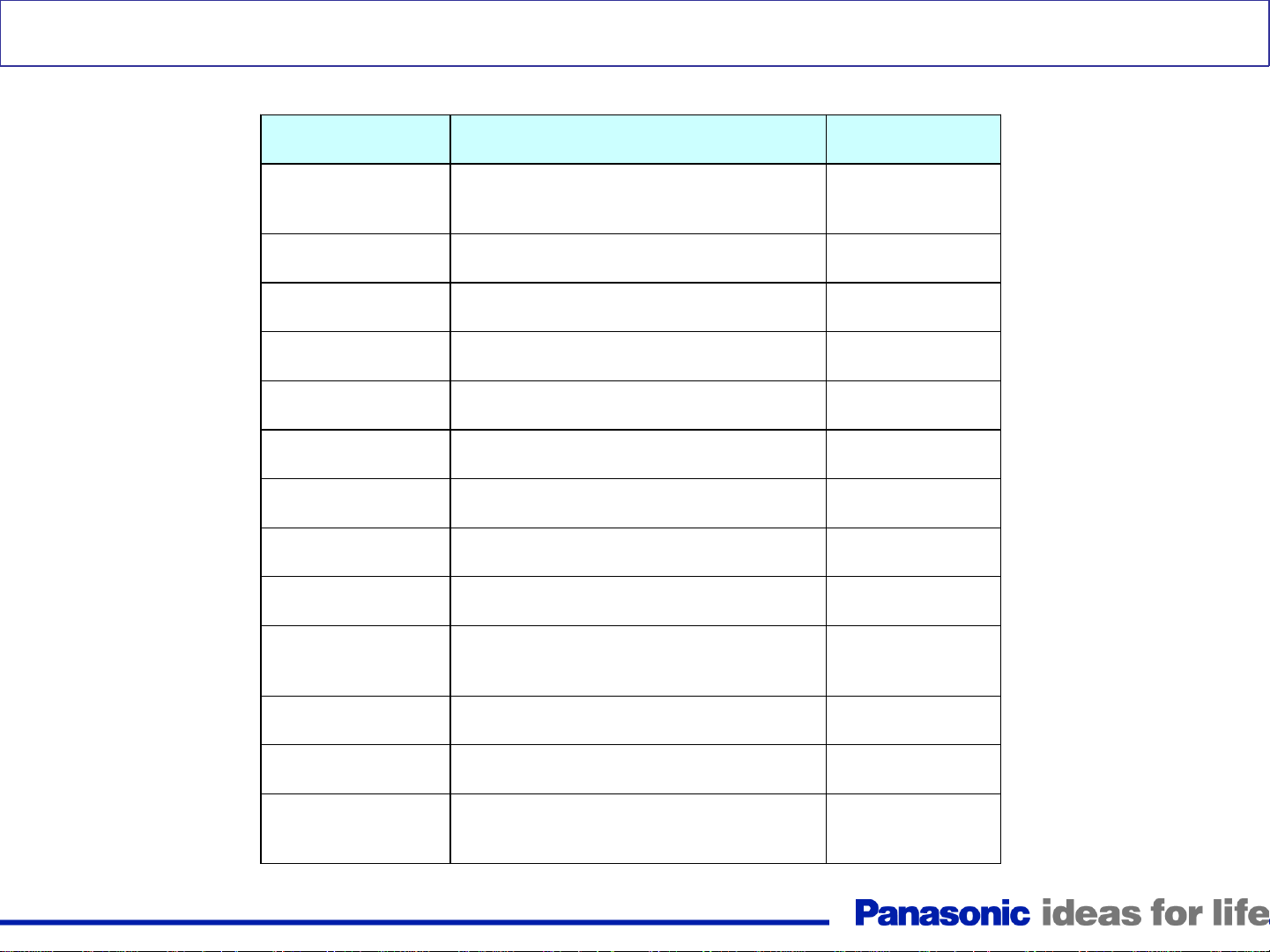
Table of Contents
Subject Page
Connector’s Location (TH-42PX80U)
Power LED’s Response to Shutdown Operation
LED blinks 1 time
LED blinks 2 times
LED blinks 3 times
LED blinks 4 times
LED blinks 5 times (Quick Troubleshooting)
LED blinks 5 times
LED blinks 6 times
SU/SD Board Isolation Procedure
LED blinks 7 times
LED blinks 8 times
LED blinks 9 times
LED blinks 10 times before pressing the power button
LED blinks 10 times after pressing the power button
LED blinks 11 times
LED blinks 12 times
5
7
8
9-11
12
13
14
15 - 18
19
20
21
23
24
25 - 27
28 - 29
30
31
Subject
No Sound
Troubleshooting for Picture Problems
Diagnostic Method for Troubleshooting PDP
Television
Troubleshooting for Picture Trouble
Diagnosis for Picture Problem (All Over the Screen)
Diagnosis of Vertical Line Problem
Picture Trouble at Upper or Lower half
Picture Trouble at Right or Left half (50 Inch)
Picture Trouble at Right or Left half (42/37 Inch)
Picture Trouble in 50 Inch Models
Picture Trouble all Over the Screen
Examples of Symptoms and Remedies
Self-check Procedure
Reset
Driver Setup Adjustment
Page
35
38
39
40
42
43
44
45
46
47
48
50
56
56
57
LED blinks 13 times
No Power / Dead
32
33 - 34
3
Introduction
<Introduction>
1. Basic concept of how to determine the defective board
1) Verification of voltages
Normally, when there is a power problem, shutdown occurs immediately.
So, to resolve a power problem, voltage checks are necessary before shutdown.
2) Check if the power comes up after disconnecting the board under suspicion.
If power comes up (*) after disconnecting a board, the board is defective.
(*) “Power comes up” equals “no shutdown”.
2. Troubleshooting Video and Audio problems
3. Examples of video problems
4. Adjustment after PCB exchange
1) After exchanging the following boards, voltage adjustment is required.
P board, SC board, SS board => Please refer to the “Service Manual”.
4
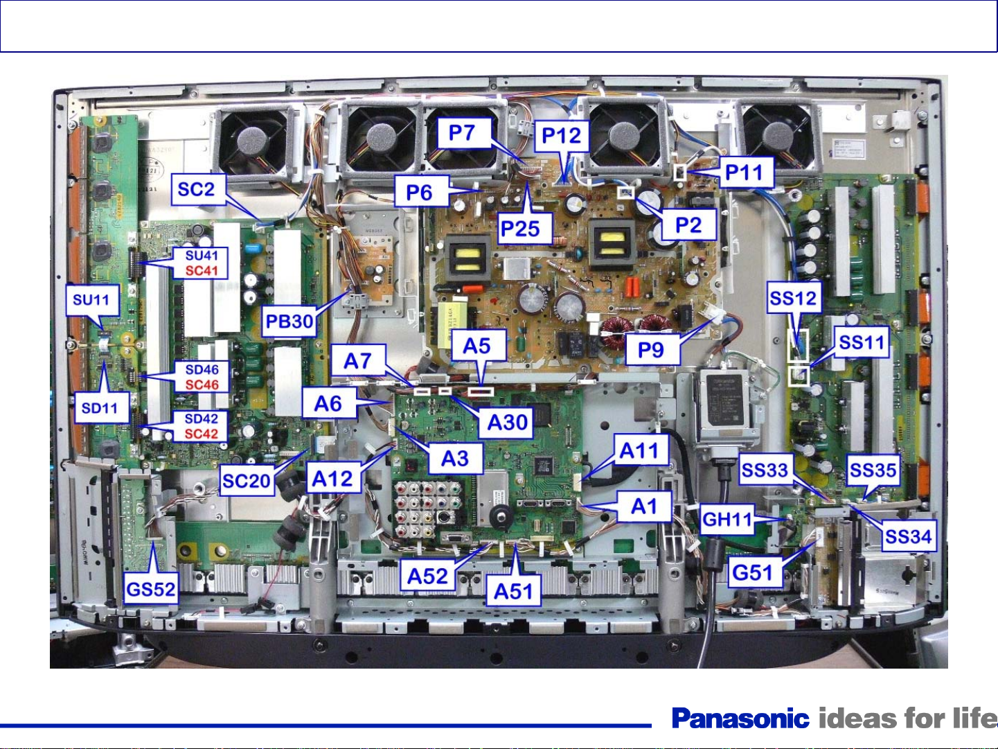
Connector’s Location (TH-42PZ85U)
Figure 1
5
1. Troubleshooting Shutdown Problems
CAUTION: Some steps requires removal of connectors and
sometimes PC boards removal. Do not let the TV run for more
than 30 seconds while connectors or boards are disconnected.
6
Power LED’s Response to Shutdown Operation
<LED Blinking timing>
Number of blinks Contents Check point
Communication Error with
1
2 15V SOS D
3 3.3V SOS D
4 Power Supply SOS P
5 5V SOS D
Microcomputer
D, A
6
7
8
9
10
11 Fan SOS PB, A
12 Sound SOS A
13
SC Energy recovery SOS
SC floating voltage SOS
SS Energy recovery SOS
Panel Configuration SOS
Sub 5V SOS, Main 3.3V SOS, DTV9V
SOS, Tuner SOS
Communication Error with Peaks
Lite-2
SC, D, P
SC, SU, SD, D, P
SS, D, P
D
A
A
7
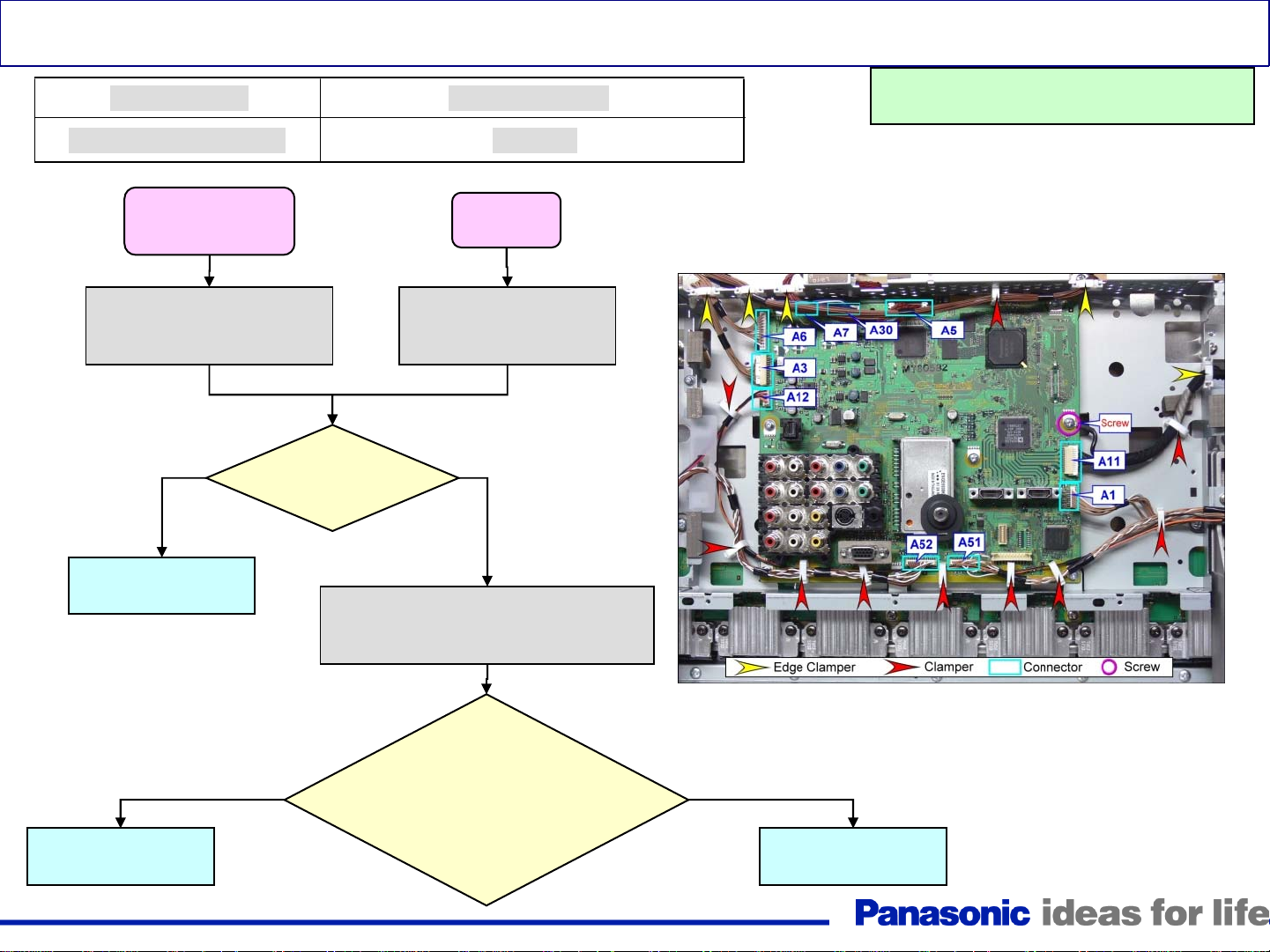
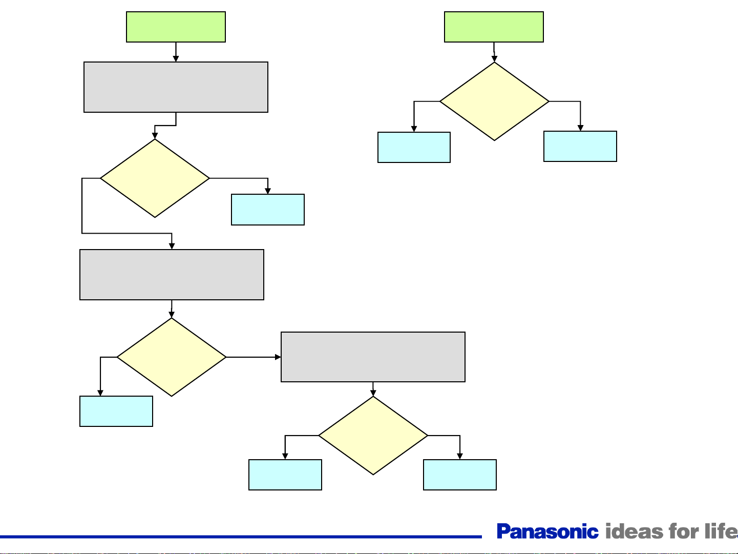
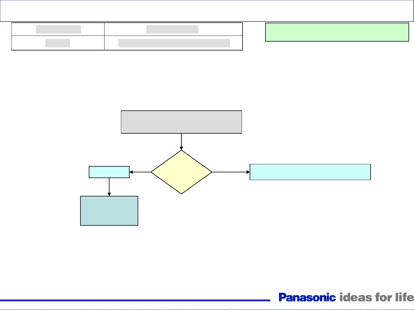
LED blinks 1 time
Trouble Mode
Communication Error
TH-42PZ80/85/800U
TH-46PZ80/85/800U
TH-50PZ80/85/800U
Disconnect A52 on the A
Board (See Figure 1). Plug
in the TV and turn it on
No Yes
Replace the GS
board
Defective Board
D, GS, A
TH-46PZ850U
TH-50PZ850U
Disconnect A9 on the A
Board. Plug in the TV
and turn it on
Is the power
LED still
blinking?
Unplug the TV and disconnect
connectors P6 and P7 on the P Board
(See Figure 1). Plug in the TV.
Warning: Disconnect AC Power prior t o
making any disconnection or connection
A board Connectors Location
Replace the D
board
No
Is the TV turning on by
itself with the following
conditions?
Power LED = Off
SC LED= On
SS LED = ON
Figure 2
Yes
Replace the A
board
8
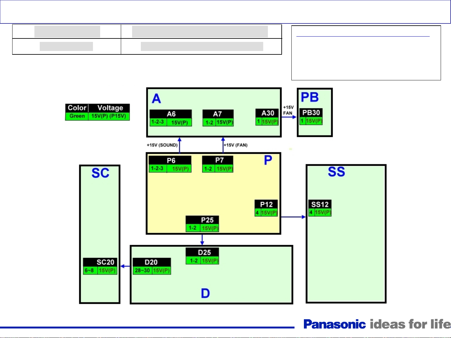
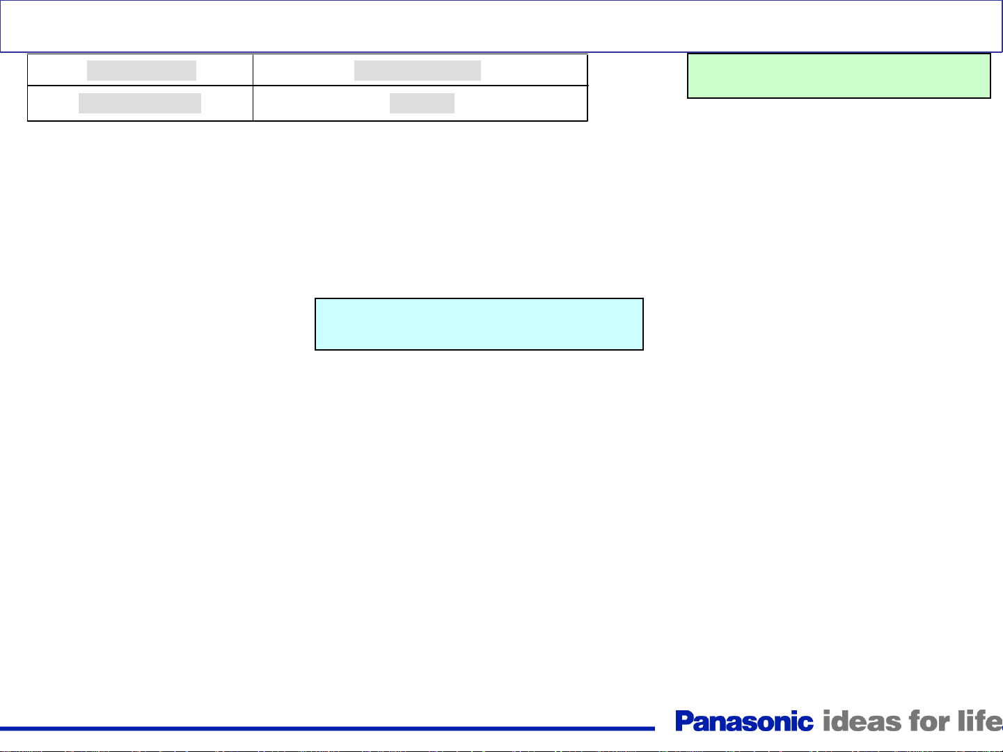
LED blinks 2 times
Trouble Mode
15V down SOS
Defective Board (Possibility)
P, A, SC, SS Board (P > A, SC, SS)
P15V Distribution
2 Blinks Condition can be caused by:
• Missing P15V
• A short of the P15V
• Wrong diagnostic by the D board
Figure 3
9
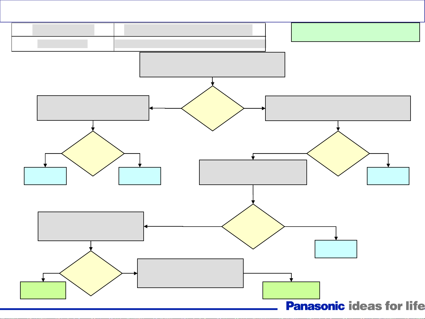
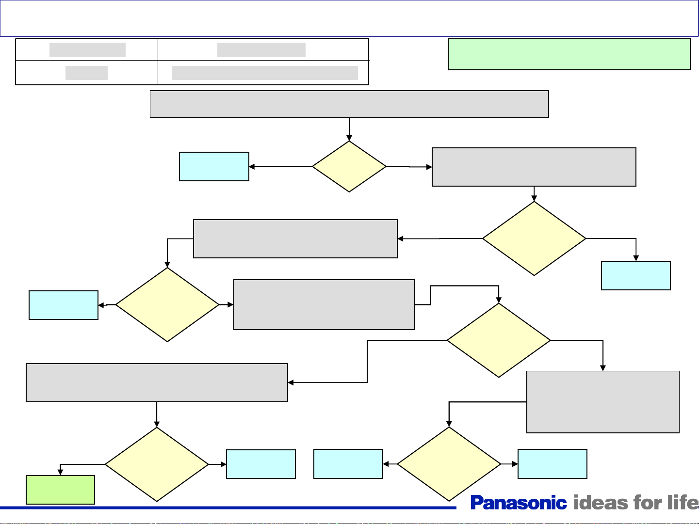
LED blinks 2 times
Trouble Mode
15V down SOS
Plug in the TV and turn it on. Measure
the voltage at pin 1 of connector P7
No
Replace
The P board
Is there
15V
present?
Defective Board (Possibility)
P, A, D, SC, SS, PB Board (P > A, SC, SS, PB)
Unplug the TV and check the resistance between
pin 1 of connector P7 and ground (Chassis)
Yes
Replace
The D board
Is there a
short
circuit?
Reconnect P12 and measure the
resistance between pin 1 of
connector P7 and ground (Chassis)
YesNo
Warning: Disconnect AC Power prior t o
making any disconnection or connection
Unplug connectors P6, P7, P12, and P25 on the P
board. Measure the resistance between pin 1 of
connector P7 and ground (Chassis)
No
Is there a
short
circuit?
Yes
Replace
The P board
Reconnect P25 and measure the
resistance between pin 1 of
connector P7 and ground (Chassis)
No
Go to the
Next slide (A)
Is there a
short
circuit?
Yes
No
Disconnect SC20 on the SC board
and measure the resistance between
pin 1 of connector P7 and ground
(Chassis
10
Is there a
short
circuit?
Yes
Replace
The SS board
Go to the
Next slide (B)
Continue from the
previous slide (A)
Reconnect P6 and measure the
resistance between pin 1 of
connector P7 and ground (Chassis
Continue from the
previous slide (B)
No
Is there a
short
circuit?
Yes
No
Is there a
short
circuit?
Is there a
short
circuit?
No
Reconnect P7 and measure the
resistance between pin 1 of
connector P7 and ground (Chassis)
Replace
The D board
Yes
Yes
Replace
The A board
Disconnect PB30 on the PB board
and measure the resistance between
pin 1 of connector P7 and ground
(Chassis)
No
The SC board
Is there a
short
circuit?
Replace
Yes
Replace
The D board
Replace
The PB board
Replace
The A board
11
LED blinks 3 times
Trouble Mode
3.3V down SOS
Defective Board
D Board
Replace the D board
Warning: Disconnect AC Power prior t o
making any disconnection or connection
12
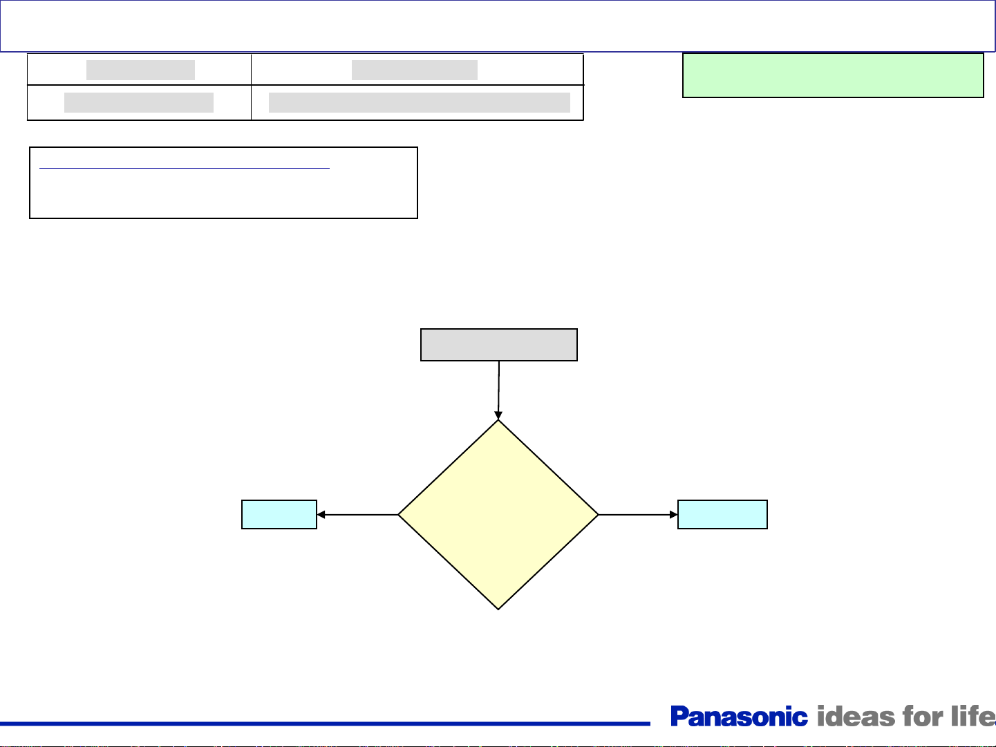
LED blinks 4 times
Trouble Mode
Power Supply SOS
Primarily P board followed by D board
Defective Board
4 blinks condition can be caused by:
An abnormal increase in any of the voltages generated
by the power supply (Vsus, Vda, P15V, P5V, STB5V)
Warning: Disconnect AC Power prior t o
making any disconnection or connection
Turn the TV on.
Is pin
Yes No
12 of CN P25
on the P
board high
before the TV
shuts down?
13
D BoardP Board
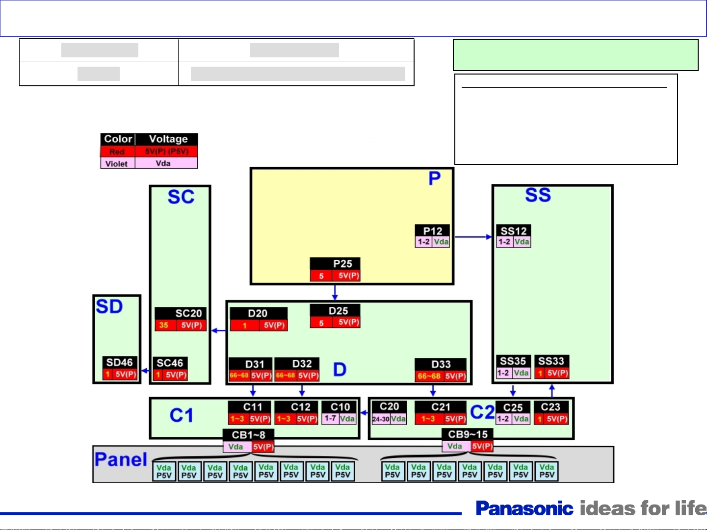
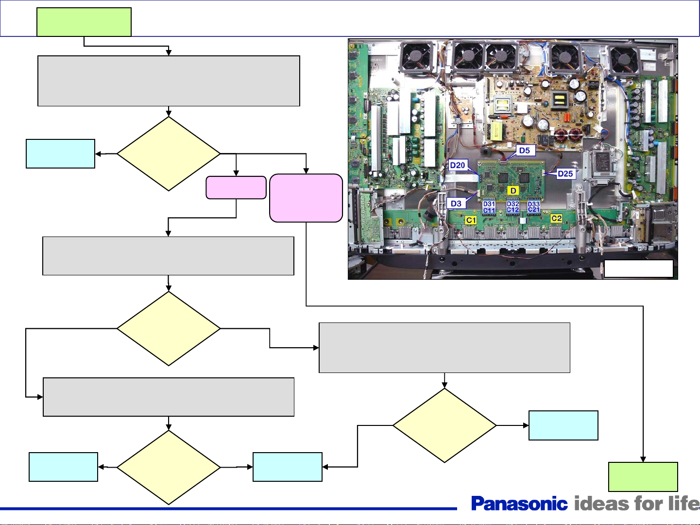
LED blinks 5 times
Trouble Mode
5V SOS
Defective Board
P, D, Cs, SC, SD, SS, D board or Panel
P5V and Vda Distribution
Warning: Disconnect AC Power prior to making any
disconnection or connection
5 blinks condition can be caused by:
• Missing P5V
• A short of the P5V
• A short of the Vda line (Note: missing
Vda from the P board does not cause 5
blinks)
• Wrong diagnostic by the D board
Figure 4
14
LED blinks 5 times (Quick Troubleshooting)
Trouble Mode
5V SOS
Defective Board
P, D, Cs, SC, SS, D board or Panel
Disconnect the TV. Measure the resistance
between pin 1 of connector P12 on the P
board and ground (Chassis).
Yes
Panel
Is there a
short to
ground?
No
Warning: Disconnect AC Power prior to making any
disconnection or connection
Proceed to more extensive troubleshooting
of the slides that follow.
Note: Even though it
does not happen often,
the 5 blinks shutdown
can also be caused by
one of the C boards
15
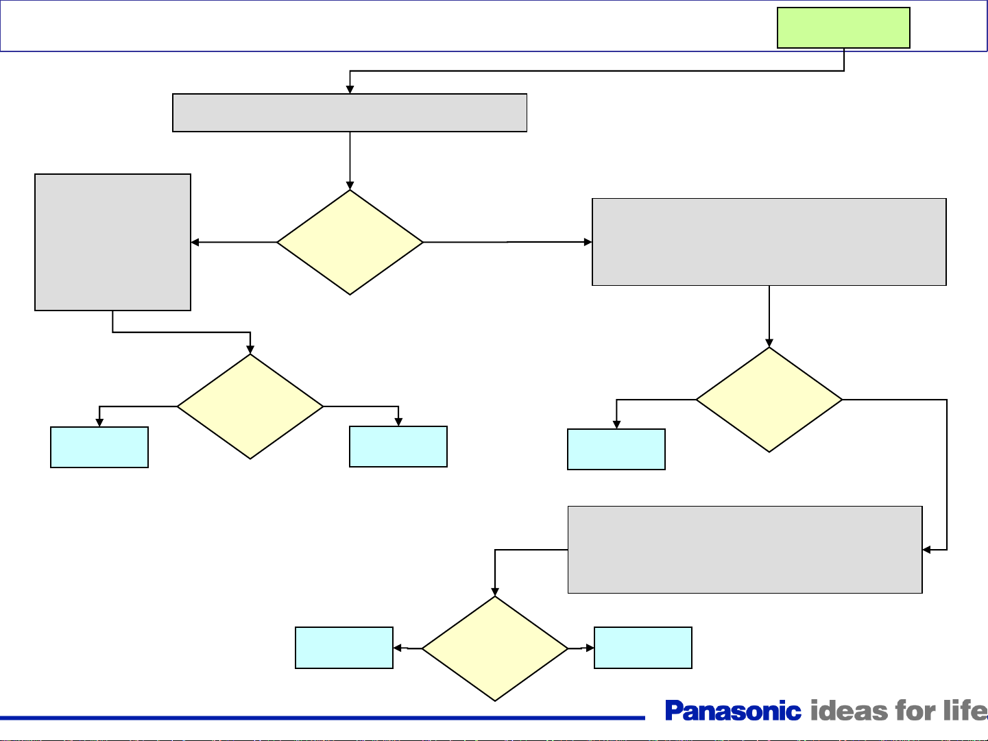
LED blinks 5 times
Trouble Mode
5V SOS
Replace
the P board
Yes
Defective Board
Warning: Disconnect AC Power prior to making any
disconnection or connection
P, C, SC, SS,SD, D board or Panel
Use a volt-meter and place the positive probe on pin 5 of connector P25 on the P board
while the negative probe is grounded. Plug in the TV and turn it on
Yes No
Replace
the D board
Is
there
5V?
Disconnect the TV and measure the
resistance between pin 5 of connector P25 on
the P board and ground (Chassis).
Yes
Disconnect P25 on the P board. Measure the
resistance between pin 5 of connector P25 on
the P board and ground (Chassis).
Reconnect P25 and disconnect SC20 on
Is there a
short to
ground?
No
the SC board. Measure the resistance
between pin 5 of connector P25 on the P
board and ground (Chassis).
Yes No
Is there a
short to
ground?
No
Is there a
short to
ground?
Replace
the P board
Reconnect SC20 and disconnect SS33 on the SS board.
Measure the resistance between pin 5 of connector P25 on
the P board and ground (Chassis).
Go to the
next slide (A)
Yes
Is there a
short to
ground?
No
Replace
the SS board
Replace
the SC board
16
Yes
Is there a
short to
ground?
Disconnect SC46 and reconnect
SC20 on the SC board. Measure
the resistance between pin 5 of
connector P25 on the P board and
ground Chassis).
No
Replace
the SD board
Continue from the
previous slide (A)
Reconnect SS33 and disconnect D31, D32, and D33 on the
D board (To get to this connectors, remove the A Board
Block Assembly). Measure the resistance between pin 5 of
connector P25 on the P board and ground (Chassis).
LED blinks 5 times
Yes No
Replace
the D board
Reconnect D31 and D32 only. Measure the resistance
between pin 5 of connector P25 on the P board and
Yes
Disconnect the Flex cables between the panel and the C1
board (CB1~CB8). Measure the resistance between pin 5
of connector P25 on the P board and ground (Chassis).
Yes
Replace
the C1 board
Is there a
short to
ground?
ground (Chassis).
Is there a
short to
ground?
Is there a
short to
ground?
TH-42PZ80/85U
No
No
TH-46PZ80/85U
TH-50PZ80/85U
TH-46PZ800/850U
TH-50PZ800/850U
Replace
the Panel
Figure 5
Reconnect D33 and disconnect the Flex cables between
the panel and the C2 board (CB9~CB15). Measure the
resistance between pin 5 of connector P25 on the P
board and ground (Chassis).
No
Is there a
short to
ground?
Yes
Replace
the C2 board
TH-42PZ85U
Go to the
next slide (B)
17
Reconnect D31 only. Measure the resistance between pin
Disconnect the Flex
cables between the
panel and the C1 board
(CB1~CB6). Measure
the resistance between
pin 5 of connector P25
on the P board and
ground (Chassis).
LED blinks 5 times
5 of connector P25 on the P board and ground (Chassis).
Yes
Is there a
short to
ground?
No
Continue from the
previous slide (B)
Reconnect D32 and D33 and disconnect C26 on the C2
board. Also disconnect the Flex cables between the panel
and the C2 board (CB7~CB11). Measure the resistance
between pin 5 of connector P25 on the P board and
ground (Chassis).
Replace
the C1 board
Yes
Is there a
short to
ground?
No
Replace
the Panel
Replace
the C3 board
Yes
Is there a
short to
ground?
18
Yes No
Replace
the C2 board
Reconnect C26 and the Flex-cables between the panel
and the C2 board. Disconnect the Flex cables between
the panel and the C3 board (CB12~CB15). Measure the
resistance between pin 5 of connector P25 on the P
board and ground (Chassis).
Is there a
short to
ground?
No
Replace
the Panel
Loading...