

Panasonic SC-CH717 Owner’s Manual
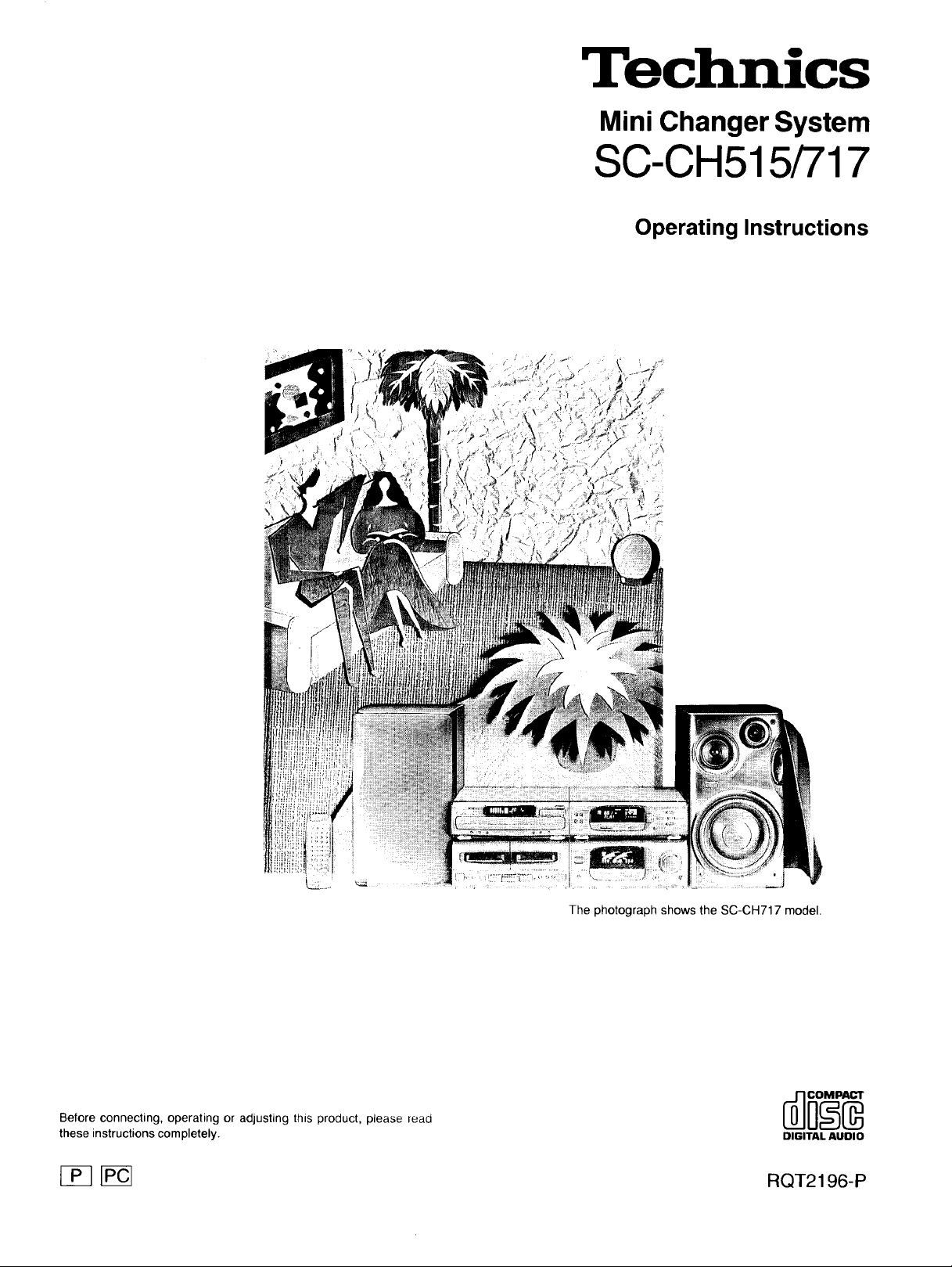
Technics
Mini Changer System
SC-CH515/717
Operating Instructions
The photograph shows the SC-CH717 model.
Before connecting, operating or adjusting this product, please read
these instructions completely. DIGITALAUDIO
[_ [_ RQT2196-P
Thank you for purchasing this product.
For optimum performance and safety, please read these operating
instructions carefully.
These operating instructions are applicable to models
SC-CH717 and SC-CH515.
These operating instructions, however, fundamentally
explain the operation of model SC-CH717.
The model number and serial number of this product can be
found on either the back or the bottom of the unit.
Please note them in the space provided below and retain
them for future reference.
MODEL NUMBER
Tuner/Sound processor
Amplifier
CD changer
Cassette deck
Speaker system
SERIAL NUMBER
CAUTION!
THIS PRODUCT UTILIZES A LASER.
USE OF CONTROLS OR ADJUSTMENTS OR PER-
FORMANCE OF PROCEDURES OTHER THAN
THOSE SPECIFIED HEREIN MAY RESULT IN HAZ-
ARDOUS RADIATION EXPOSURE.
DO NOT OPEN COVERS AND DO NOT REPAIR
YOURSELF. REFER SERVICING TO QUALIFIED
PERSONNEL.
WARNING:
TO REDUCE THE RISK OF FIRE OR ELEC-
TRIC SHOCK, DO NOT EXPOSE THIS APPLI-
ANCE TO RAIN OR MOISTURE.
CAUTION
CAUTION: TO REDUCE THE RISK OF ELECTRIC
___i= The lightning flash with arrowhead symbol, within
CAUTION:
TO PREVENT ELECTRIC SHOCK MATCH
WIDE BLADE OF PLUG TO WIDE SLOT,
FULLYINSERT.
SHOCK, DO NOT REMOVE SCREWS.
NO USER-SERVICEABLE PARTS
INSIDE.
REFER SERVICING TO QUALIFIED
SERVICE PERSONNEL.
an equilateral triangle, is intended to alert the user
to the presence of uninsulated "dangerous voltage"
within the product's enclosure that may be of suffi-
cient magnitude to constitute a risk of electric shock
to persons.
The exclamation point within an equilateral triangle
is intended to alert the user to the presence of
important operating and maintenance (servicing)
instructions in the literature accompanying the ap-
2
CAUTION:
This equipment has been tested and found to comply with the
limitsfor a Class B digital device, pursuant to Part 15 of the FCC
Rules.
These limits are designed to provide reasonable protection
against harmful interference in a residential installation. This
equipment generates, uses and can radiate radio frequency en-
ergy and, if not installed and used in accordance with the instruc-
tions, may cause harmful interference to radio communications.
However, there is no guarantee that interference will not occur in
a particular installation. If this equipment does cause harmful
interference to radio or television reception, which can be deter-
mined by turning the equipment off and on, the user is encour-
aged to try to correct the interference by one of the following
measures:
eReorient or relocate the receiving antenna.
elncrease the separation between the equipment and receiver.
• Connect the equipment into an outlet on a circuit different from
that towhich the receiver is connected.
eConsult the dealer or an experienced radio/TV technician for
help.
FCC Notice: This system complies with new Part 15, except for
the radio receiver, which complies with old Part 15, Subpart C of
the FCC Rules. Operation is subject to the following two condi-
tions: (1) This device may not cause harmful interference, and
(2) this device must accept any interference received, including
interference that may cause undesirable operation. The radio re-
ceiver is not subject to above item (2).
Any unauthorized changes or modifications to this equipment
would void the user's authority to operate this device.
Before use
Recording operations
Precautions .............................. 4
Supplied accessories ...................... 6
Installation ............................... 7
Stacking the components ............................. 7
Connections ............................. 8
Optional antenna connections ......................... 10
External unit connection .............................. 11
Location of controls ....................... 12
Amplifier section .................................... 12
Tuner/sound processor section ........................ 12
Compact disc changer section ......................... 13
Cassette deck section ................................ 13
Preparations
Concerning the remote control .............. 14
Battery instaffation ................................... 14
Correct method of use ............................... 14
Concerning the multi-control section ......... 15
Setting the time ........................... 16
Memory presetting ........................ 17
Automatic memory presetting .......................... 17
Manual memory presetting ............................ 18
Compact disc operations
Listening to compact discs ................. 19
Sequential play ..................................... 19
Program play ....................................... 22
Direct access play ................................... 24
Random play ....................................... 24
Radio operations
Listening to radio broadcasts ............... 25
Manual tuner operation ............................... 25
Memory tuner operation .............................. 25
Making a recording from radio broadcasts .... 30
Recording from compact discs .............. 33
One-touch editing preparation ......................... 34
To start one-touch editing ............................ 34
Program edit-recording (LAST FADE mode only) .......... 36
Linking up several discs (LINK) ........................ 37
Synchro recording .................................. 38
Tape-to-tape recording ..................... 39
Volume level mode operations
Changing the volume level mode ............ 40
Changing the output level display ...................... 40
Changing the output level scale ........................ 40
Tone quality operations
Changing the tone ........................ 41
About equalization curves (EQ) ........................ 41
About simulated listening environments (SPACE) .......... 41
To retrieve the preprogrammed equalization curves
(EQ mode) ...................................... 42
To retrieve the preprogrammed simulated listening
environments (SPACE mode) ........................ 43
To adjust EQ and SPACE ("USER" mode) ............... 44
To listen with augmented bass (V.BASS) ................ 44
Timer operations
Using the timer ........................... 45
About the types of timer operation ...................... 45
Setting the play timer ................................ 46
Setting the record timer .............................. 48
To use the sleep timer ............................... 50
To use each timer mode in conjunction .................. 51
Microphone mixing
Tape deck operations
Listening to tapes ......................... 26
Playback .......................................... 26
Sequential playback between 2 tapes ................... 28
Convenient functions
Convenient functions ...................... 29
Easy play ......................................... 29
To mute the volume ................................. 29
To adjust the left-right volume balance ................... 29
To use headphones ................................. 29
Enjoying microphone mixing ............... 52
External unit operations
Using an external unit ..................... 53
Listening to an external source ........................ 53
Recording from an external source ..................... 53
Reference
Remote control operations
mquick referencem . .................... 54
Concerning compact discs ................. 56
Maintenance ............................. 57
Concerning cassette tapes ................. 57
Troubleshooting guide ..................... 58
Product service ........................... 59
Technical specifications ........... Back cover
3
Before using this unit please read these operating instructions care-
fully. Take special care to follow the warnings indicated on the unit
itself as well as the safety suggestions listed below.
Afterwards keep them handy for future reference.
1. Power Source--The unit should be connected to power supply
only of the type described in the operating instructions or as
marked on the unit.
2. Polarization--If the unit is equipped with a polarized AC power
plug (a plug having one blade wider than the other), that plug will
fit into the AC outlet only ORe way. This is a safety feature. If you
are unable to insert the plug fully into the outlet, try reversing the
plug. If the plug should still fail to fit, contact your electrician to
replace your obsolete outlet. Do not defeat the safety purpose of
the polarized plug.
3. Power Cord Protection--AC power supply cords should be
routed so that they are not likely to be walked on or pinched by
items placed upon or against them. Never take hold of the plug or
cord if your hand is wet, and always grasp the plug body when
connecting or disconnecting it.
4. Nonuse Periods--When the unit is not used, turn the power off.
When left unused for a long period of time, the unit should be
unplugged from the household AC outlet.
Installation
Environment
1,
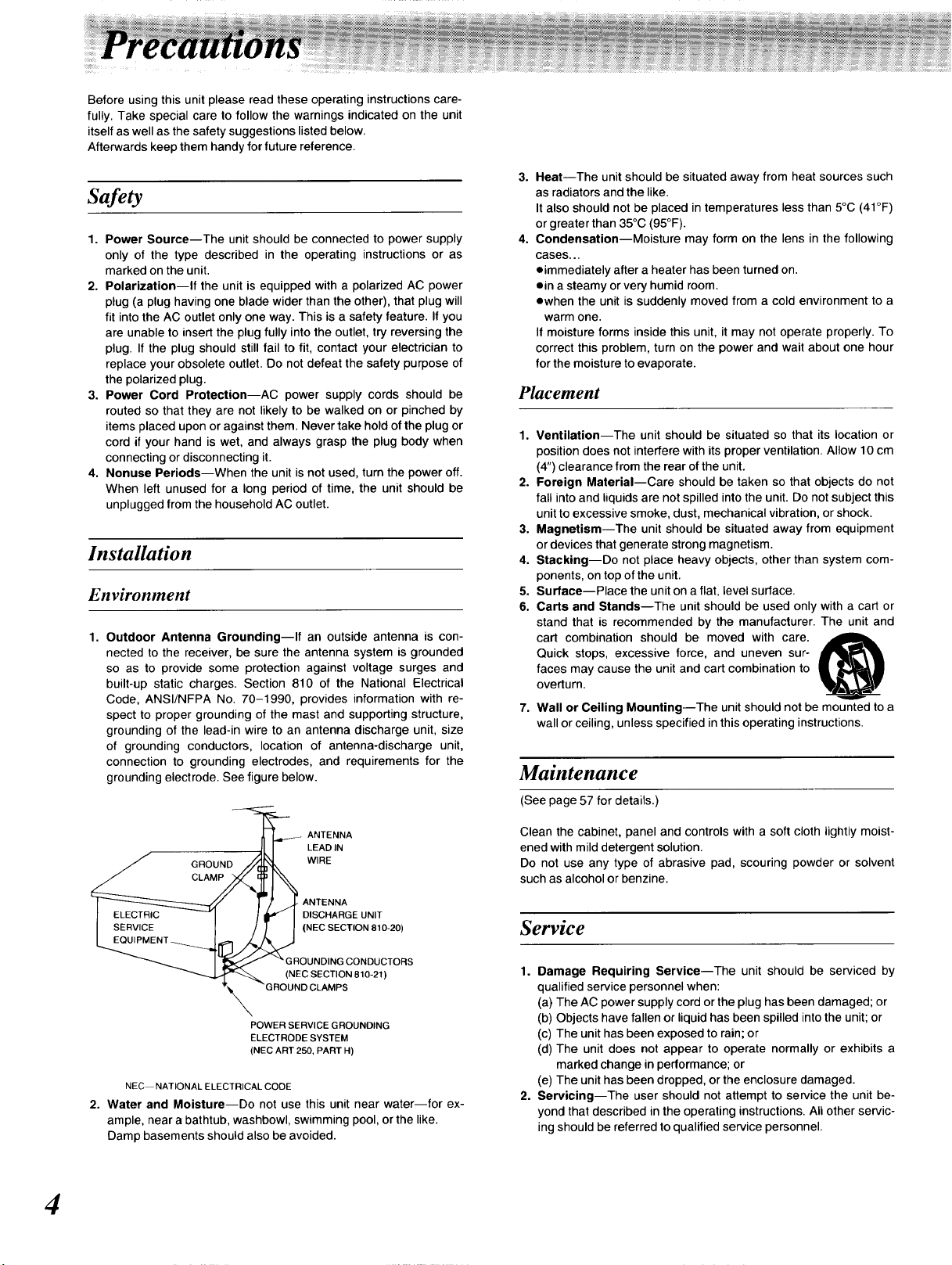
Outdoor Antenna Grounding--If an outside antenna is con-
nected to the receiver, be sure the antenna system is grounded
so as to provide some protection against voltage surges and
built-up static charges. Section 810 of the National Electrical
Code, ANSI/NFPA No. 70-1990, provides information with re-
spect to proper grounding of the mast and supporting structure,
grounding of the lead-in wire to an antenna discharge unit, size
of grounding conductors, location of antenna-discharge unit,
connection to grounding electrodes, and requirements for the
grounding electrode. See figure below.
3.
Heat--The unit should be situated away from heat sources such
as radiators and the like.
It also should not be placed in temperatures less than 5°C (41°F)
or greater than 35°C (95°F).
4,
Condensation--Moisture may form on the lens in the following
cases...
eimmediately after a heater has been turned on.
ein a steamy or very humid room.
ewhen the unit is suddenly moved from a cold environment to a
warm one.
If moisture forms inside this unit, it may not operate properly. To
correct this problem, turn on the power and wait about one hour
for the moisture to evaporate.
Placement
1. Ventilation--The unit should be situated so that its location or
position does not interfere with its proper ventilation. Allow 10 cm
(4") clearance from the rear of the unit.
2. Foreign Material--Care should be taken so that objects do not
fall into and liquids are not spilled into the unit. Do not subject this
unit to excessive smoke, dust, mechanical vibration, or shock.
3. Magnetism--The unit should be situated away from equipment
or devices that generate strong magnetism.
4. Stacking--Do not place heavy objects, other than system com-
ponents, on top of the unit.
5. Surface--Place the unit on a flat, level surface.
6. Carts and Stands--The unit should be used only with a cart or
stand that is recommended by the manufacturer. The unit and
cart combination should be moved with care.
Quick stops, excessive force, and uneven sur-
faces may cause the unit and cart combination to
overturn.
7. Wall or Ceiling Mounting--The unit should not be mounted to a
wall or ceiling, unless specified in this operating instructions.
Maintenance
(See page 57 for details.)
_ ANTENNA
,ILI LEADIN
GRoo.o W,RE
[ _ ! / 14"ANTENNA
J ELECTRIC --I / it" I DISCHARGEUNIT
_;CENT _._J[_ _ 'NEe SECTION 810-20)
I _ - GROUNDING CONDUCTORS
_'_,_ (NEC SECTION 810-21 )
"_'x "GROUND CLAMPS
POWER SERVICE GROUNDING
ELECTRODE SYSTEM
(NEC ART 250, PART H)
NEC NATIONAL ELECTRICALCODE
2. Water and Moisture--Do not use this unit near water--for ex-
ample, near a bathtub, washbowl, swimming pool, or the like.
Damp basements should also be avoided.
4
Clean the cabinet, panel and controls with a soft cloth lightly moist-
ened with mild detergent solution.
Do not use any type of abrasive pad, scouring powder or solvent
such as alcohol or benzine.
Service
1. Damage Requiring Service--The unit should be serviced by
qualified service personnel when:
(a) The AC power supply cord or the plug has been damaged; or
(b) Objects have fallen or liquid has been spilled into the unit; or
(c) The unit has been exposed to rain; or
(d) The unit does not appear to operate normally or exhibits a
marked change in performance; or
(e) The unit has been dropped, or the enclosure damaged.
2. Servicing--The user should not attempt to service the unit be-
yond that described in the operating instructions. All other servic-
ing should be referred to qualified service personnel.
Listening caution
Selecting fine audio equipment such as the unit you've just pur-
chased is only the start of your musical enjoyment. Now it's time to
consider how you can maximize the fun and excitement your equip-
ment offers. This manufacturer and the Electronic Industries Associ-
ation's Consumer Electronics Group want you to get the most out of
your equipment by playing it at a safe level. One that lets the sound
come through loud and clear without annoying blaring or
distortion--and, most importantly, without affecting your sensitive
hearing.
Sound can be deceiving. Over time your hearing "comfort level"
adapts to higher volumes of sound. So what sounds "normal" can
actually be loud and harmful to your hearing.
Guard against this by setting your equipment at a safe level BE-
FORE your hearing adapts.
To establish a safe level:
oStart your volume control at a low setting.
oSIowly increase the sound until you can hear it comfortably and
clearly, and without distortion.
Once you have established a comfortable sound level:
oSet the dial and leave it there.
Taking a minute to do this now will help to prevent hearing damage or
loss in the future. After all, we want you listening for a lifetime.
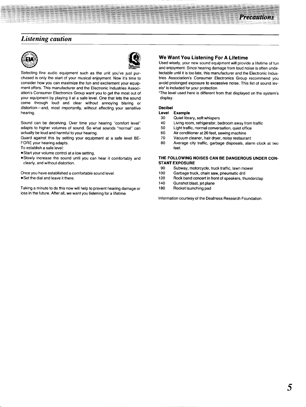
We Want You Listening For A Lifetime
Used wisely, your new sound equipment will provide a lifetime of fun
and enjoyment. Since hearing damage from loud noise is often unde-
tectable until it is too late, this manufacturer and the Electronic Indus-
tries Association's Consumer Electronics Group recommend you
avoid prolonged exposure to excessive noise. This list of sound lev-
els* is included for your protection.
*The level used here is different from that displayed on the system's
display.
Decibel
Level
Example
30
Quiet library, soft whispers
40
Living room, refrigerator, bedroom away from traffic
5O
Light traffic, normal conversation, quiet office
60
Air conditioner at 20 feet, sewing machine
70
Vacuum cleaner, hair dryer, noisy restaurant
8O
Average city traffic, garbage disposals, alarm clock at two
feet.
THE FOLLOWING NOISES CAN BE DANGEROUS UNDER CON-
STANT EXPOSURE
90 Subway, motorcycle, truck traffic, lawn mower
100 Garbage truck, chain saw, pneumatic drill
120 Rock band concert infront ofspeakers, thunderclap
140 Gunshot blast, jet plane
180 Rocket launching pad
Information courtesy of the Deafness Research Foundation.
5
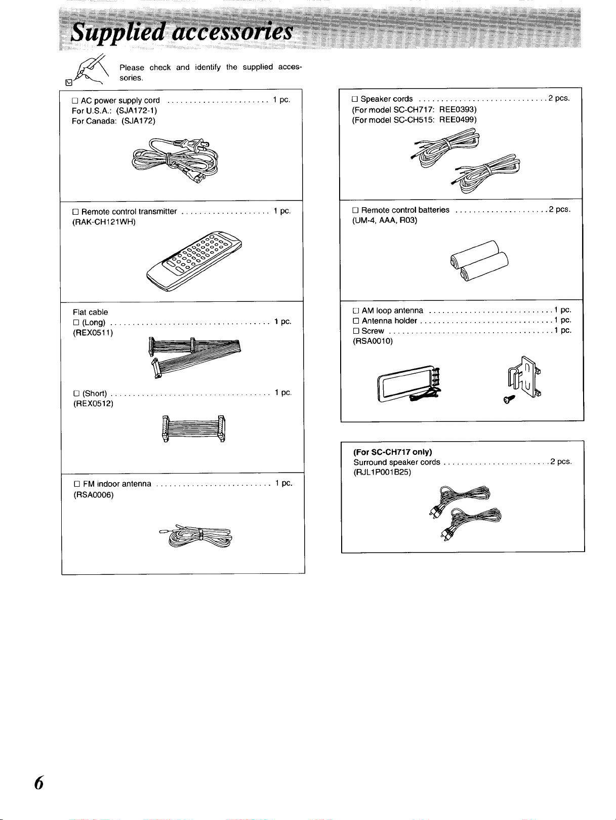
Please check and identify the supplied acces-
[]
[] AC power supply cord ....................... 1 pc.
For U.S.A.: (SJA172-1)
For Canada: (SJA172)
sories.
[] Speaker cords ............................. 2 pcs.
(For model SC-CH717: REE0393)
(For model SC-CH515: REE0499)
[] Remote control transmitter .................... 1 pc.
(RAK-CH121WH)
Flat cable
[] (Long) .................................... 1 pc.
(REX0511 )
[] (Short) .................................... 1 pc.
(REX0512)
[] FM indoor antenna .......................... 1 pc.
(RSA0006)
[] Remote control batteries ..................... 2 pcs.
(UM-4, AAA, R03)
[] AM loop antenna ............................ 1 pc.
[] Antenna holder .............................. 1 pc.
[] Screw ..................................... 1 pc.
(RSA0010)
(For SC-CH717 only)
Surround speaker cords ........................ 2 pcs.
(RJL1P001 B25)
6
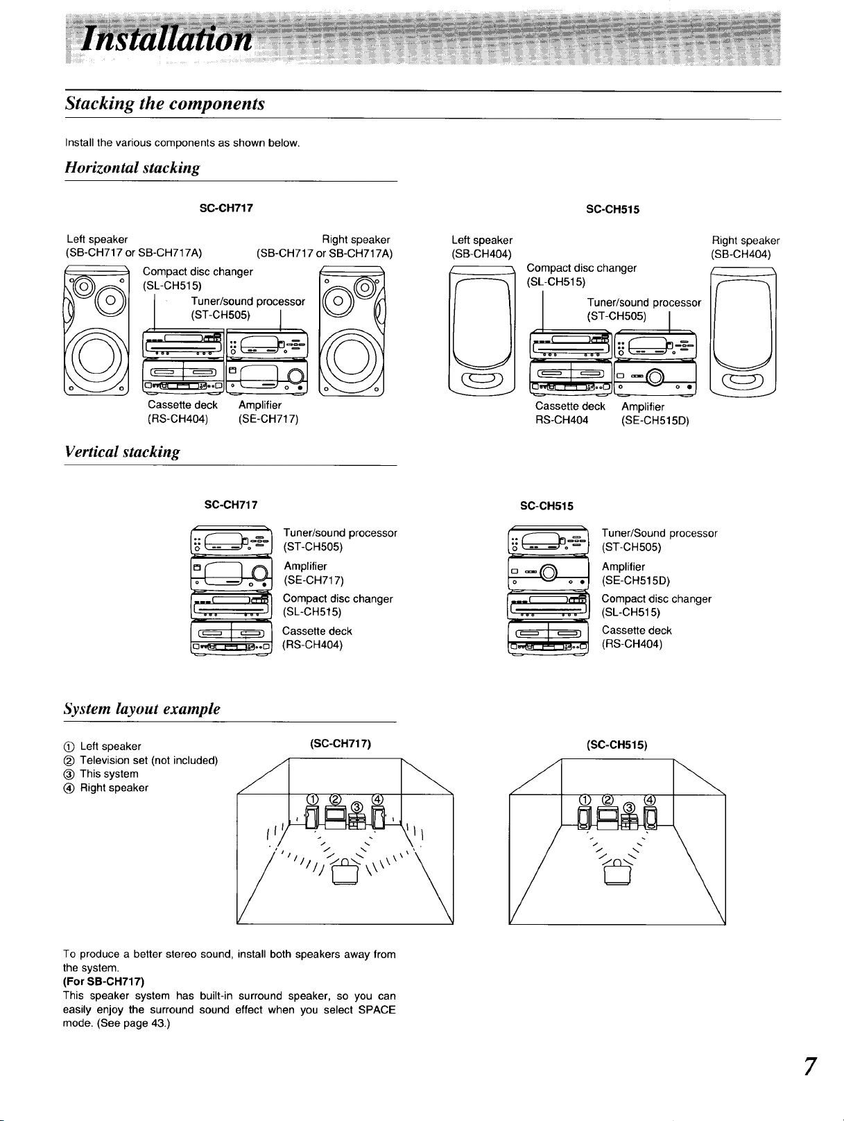
Stacking the components
Install the various components as shown below.
Horizontal stacking
Left speaker
SB-CH717 or SB-CH717A)
Compact disc changer
(SL-CH515)
Cassette deck Amplifier
(RS-CH404) (SE-CH717)
Vertical stacking
S0-CH717
(SB-CH717 or SB-CH717A)
Tuner/sound processor
(ST-CH505) I
SC-CH717
Tuner/sound processor
(ST-CH505)
Amplifier
(SE-CH717)
Compact disc changer
(SL-CH515)
Cassette deck
(RS-CH404)
Right speaker
Left speaker
(SB-CH404
S0-0H515
Compact disc changer
(SL-CH515)
Tuner/sound processor
I iST-CHSO )I
Cassette deck Amplifier
NS-CH404 (SE-CH515D)
SC-0H515
( -i
:j
.___,"PR
[ ooo ooo
Tuner/Sound processor
(ST-CH505)
Amplifier
(SE-CH515D)
Compact disc changer
(SL-CH515)
Cassette deck
(RS-CH404)
Right speaker
(SB-CH404)
System layout example
(_) Left speaker
_) Television set (not included)
(_) This system
(_ Right speaker
To produce a better stereo sound, install both speakers away from
the system.
(For SB-CH717)
This speaker system has built-in surround speaker, so you can
easily enjoy the surround sound effect when you select SPACE
mode. (See page 43.)
(SO-OH717)
(SC-CH515)
\\
7
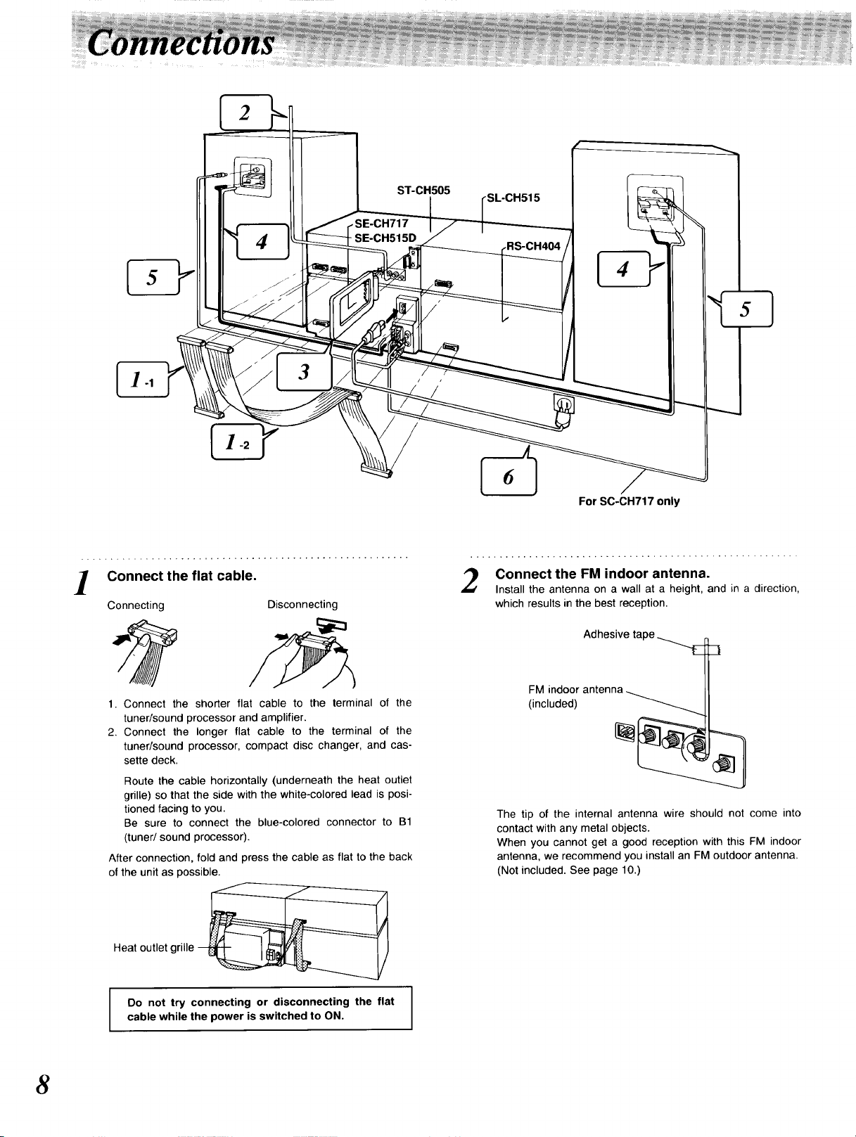
ST-CH505
E-CH717
- SE-CH515D
_L-CH515
For SC-CH717 only
Connect the flat cable.
Connecting
1. Connect the shorter flat cable to the terminal of the
tuner/sound processor and amplifier.
2. Connect the longer flat cable to the terminal of the
tuner/sound processor, compact disc changer, and cas-
sette deck.
Route the cable horizontally (underneath the heat outlet
grille) so that the side with the white-colored lead is posi-
tioned facing to you.
Be sure to connect the blue-colored connector to B1
(tuner/sound processor).
After connection, fold and press the cable as flat to the back
of the unit as possible.
Heat outlet grille
Disconnecting
Connect the FM indoor antenna.
Install the antenna on a wall at a height, and in a direction,
which results in the best reception.
Adhesive tape
FM indoor antenna
(included)
The tip of the internal antenna wire should not come into
contact with any metal objects.
When you cannot get a good reception with this FM indoor
antenna, we recommend you install an FM outdoor antenna.
(Not included. See page 10.)
8
Do not try connecting or disconnecting the flat
cable while the power is switched to ON.
_ _ !i!_ _!_, !_ _!!_i!! i_ _!_!_!i__!_i_i !!i!,z!!!__ i!!_i_i!!_!!!!i_!_!__!i!_z_i!!_!!!!!!!_i!¸i_i_i!_!_!ii_ii!!!!_!i!!i!_i_i!!i!!!!_!!i!iiiiiii_!_!!iiii_i_!!!!_!iiii!_!_!_iiiiiiii_!_!!iiiiiiii_!!i!iiiii!_!_!iii!ii!iii_ii!i!i!i!i!i_iz!_i!!i!i!_ _:_ __:_____z_:_ __ __ _ _ __ ___ _ _ _ __ __ __ _¸_i_iiiii_i__z_i_iiiiiii!iiiii_ii_iiiiiii_i_i_iii_iii_i_i_i_iiii_i_i_iiii_i_i_i_i_i_i_iiiiiiiiii_i_i_iil
_iiiiiii_iiiii_iiiiii_iiiiiiiiiiiiiiiiiiiiiiiiiiiiiiiiiiiiiiiiiiiiiiiiiiiiiiiiiiiiiiiiiiiiiiiiiiiiiiiiiiiiii iiiiiiiii_iiiiii_iiiiiiiiiiiiiii_iiii_i iiiiii!iiiiiiiiiiiiii_!iiiii!iiiii!ii!iiiiiii!iiiiiii_ iiiiii_iiiii_iiiii_i iiii_iiii_ii i_ iiii_iii _iii_ii_iiii_ii _ii_ ii_i ii_ i_iiiil _iiii_iii_i_i_i_i_i_i_ii_i_i_iii_i_i_i_i_i_i_i_i_i_i_i_i_i_i_i_i_i_i_ _i_'_'_ _'__i_'_'_'_ _ii_
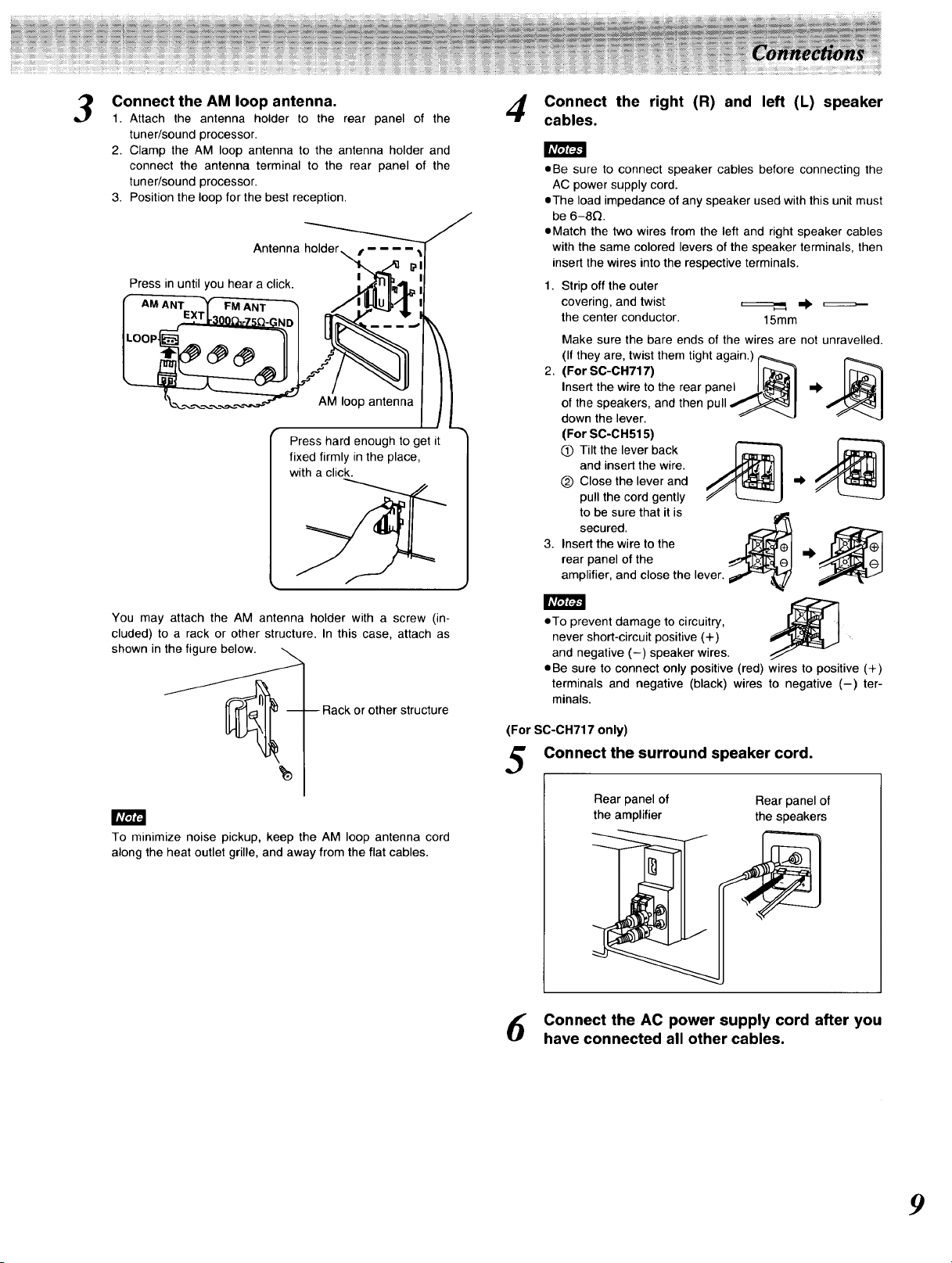
Connect the AM loop antenna. /,_ Connect the right (R) and left (L) speaker
1. Attach the antenna holder to the rear panel of the "7' cables.
tuner/sound processor.
2. Clamp the AM loop antenna to the antenna holder and
connect the antenna terminal to the rear panel of the
tuner/sound processor.
3. Position the loop for the best reception.
Antenna holder
Press in until you hear a click.
AM loop antenna
Press hard enough to get it
fixed firmly in the place,
with a click.
• Be sure to connect speaker cables before connecting the
AC power supply cord.
eThe load impedance of any speaker used with this unit must
be 6-8£_.
• Match the two wires from the left and right speaker cables
with the same colored levers of the speaker terminals, then
insert the wires into the respective terminals.
1. Strip off the outer
covering, and twist =_====,, _),
the center conductor. 15mm
Make sure the bare ends of the wires are not unravelled.
(If they are, twist them tight again.) I'_
2.
(For SC-CH717) II_--_]
Insert the wire to the rear panel .._11_ I _
of the speakers, and then pull _ I
down the lever. _ "'J
(For SC-CH515)
Q Tilt the lever back
and insert the wire.
(_ Close the lever and
pull the cord gently
to be sure that it is
secured.
3. Insert the wire to the
rear panel of the
amplifier, and close the lever.
You may attach the AM antenna holder with a screw (in-
cluded) to a rack or other structure. In this case, attach as
-- -- Rack or other structure
shown in _
To minimize noise pickup, keep the AM loop antenna cord
along the heat outlet grille, and away from the flat cables.
• To prevent damage to circuitry, J,_F_ t
never short-circuit positive (+)
and negative (-) speaker wires.
• Be sure to connect only positive (red) wires to positive (+)
terminals and negative (black) wires to negative (-) ter-
minals.
(For SC-CH717 only)
Connect the surround speaker cord.
Rear panel of Rear panel of
the amplifier the speakers
Connect the AC power supply cord after you
have connected all other cables.
9
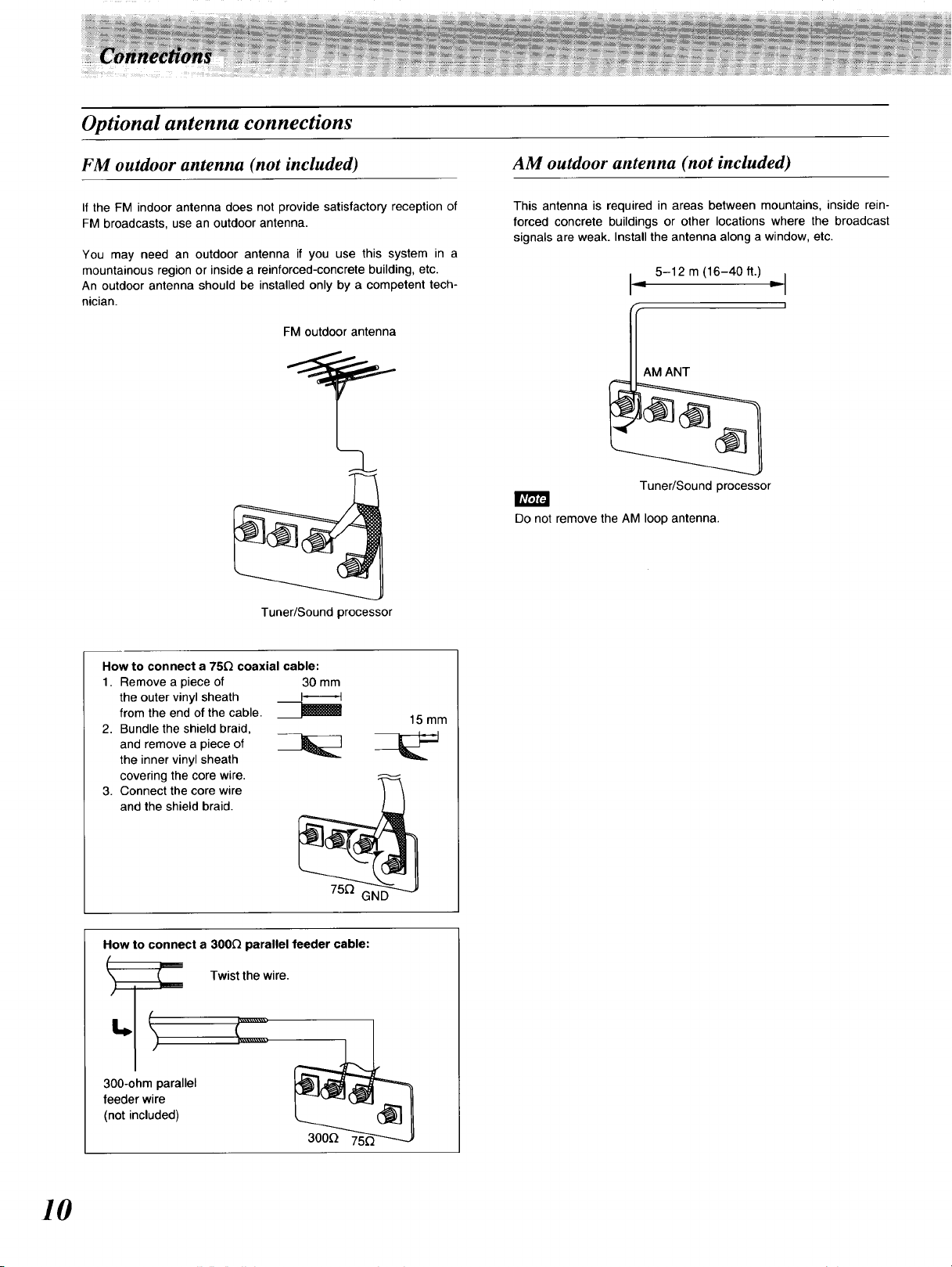
Optional antenna connections
FM outdoor antenna (not included)
If the FM indoor antenna does not provide satisfactory reception of
FM broadcasts, use an outdoor antenna.
You may need an outdoor antenna if you use this system in a
mountainous region or inside a reinforced-concrete building, etc.
An outdoor antenna should be installed only by a competent tech-
nician.
FM outdoor antenna
Tuner/Sound processor
AM outdoor antenna (not included)
This antenna is required in areas between mountains, inside rein-
forced concrete buildings or other locations where the broadcast
signals are weak. Install the antenna along a window, etc.
_ 5-12 m (16-40 ft.) _11
]
AM ANT
Tuner/Sound processor
Do not remove the AM loop antenna.
How to connect a 75£2 coaxial cable:
1. Remove a piece of 30 mm
the outer vinyl sheath _
from the end of the cable. __,l_ll
2. Bundle the shield braid,
and remove a piece of __]___
the inner vinyl sheath
covering the core wire.
3. Connect the core wire
and the shield braid.
How to connect a 300_ parallel feeder cable:
Twist the wire.
C
300-ohm parallel
feeder wire
(not included)
15ram
10
_ _ _:_:_: _ _ _:::__::::__ _:_:_:___:_=::_:_:_::::::::::__::::::::=_:=:::_:::_:_:: _:_:_!_!:::__:_ _:z_: ___zz__ ___ ____ _____ ____:: _:::::_........................i= iii_:::i i ii::i ii i!!:i:ii!i!!izi:ii!!!!ii_:i:i!ii!i!i!i_iz_!_!i!i!iii_i_i__iiiiiiii_i!iii!]ii_ii:_!_i_iiiii]iii___i]iiiiiii___iiii]i]ii_iii_i_iiiiiiiii_i_iii_ii_]i_i__iiiiiiiii_i_ii_iiiiiiii_ii__iiiiiiiii__i_i]iii_ii__iiiii]i_i_i_iii]iiiiiii___i]iiii_ii_ii_i iiii_ii_iiiiiiiii_i]iiii_i_i_i_i_iiiiiii_i_i_i_iiiii_i_iii]i]iiii_iiiiiii]ii_i_i_iiiiiiiii____i_ __i_ _iiii_i__ii¸iiii_ iii]iiiii_iii_iiiiiii_ii_iiiiiiii_i_i iiiiiii_i
_i_i_i_i_i_i_ii_i_i_i_i_i_ii_iiiiiiii_i_i_!_!iiiiiii!i!_!_!!!i!iii!i!ii!!!!!i!i!i!i!!!i!i!i!i_i!!!i!i!i_i!!i!!!i!_!iiii_i!iiiiii_!iiiiiiiiiiiiiiiiii_i_i!iiii_i_i_iii_iiiiiiii iiiiiiiiiiii iiiiiiiiiiiiiiiiiiiiiiiiiii iiiiiii_iiiiii_iiiiiii;ii!iiiii_iiiii __________________________________________________________________________________________________________`________________________________________________`_________________________________<___________________,,,,:,/_:_.......... _:::::::ii_..... _:_:::_i : ::i" ::_iiiiiiiiiii_!
i_!_i_!i_i!i!i_i_i_i_i!i_i_iii_i_:i:=_i_ilii:::i!_i_i!i!i!i!_:_i_!_!_!_!_!_!:!:!_!_!_!_!_!_!_!_!_!_!_!_!_!_!_!_!_!_!_!_!_!_!_!_!_!_!_!_!_!_!_!_!_!_!_!_!_!_!_!_!_!_!_!_!_!_!_!_!_!_!_!_!_!_!_!_!_i_!_!_!_i_i_!_i_!_!_!_ii!_!_!:i_!:!_!'!_i_ii!i!i!'ii!_!!!i!i!i!i!i!!!:!_!!!!!!!!!!!!!!_!!!!!!!!!!!iii!i!i!i!i!!!!ii!i!!!!_!i!!!!i!!!!!!!!!!!!!!!!!!!!!!!!!!_!!!!!!!!!!!!!!!_!!!!!!!!!!!!_!!!!!!!!!!!!!_!!!!!!!!!!_!!!!!!!!_!!!i!!!i!_i!!!!!i!i_i!!i!i!i!!_i !i!i!i!i_i!i!i!i_i!i!iii_iiiiiii_iiiiiiii_iiiiii_]iiiii i_]iiii ii_i i]iiii_iii_iiiiiii_i iiiiiii_iiiiii_iiii i_iii ii_iiiiii@iiiii i_i iiii@iiiiii,_!,iiiii_ii_iiiii i!_!i!_!_!_ _!_!_!_!_!_!_!_!i!_!_!
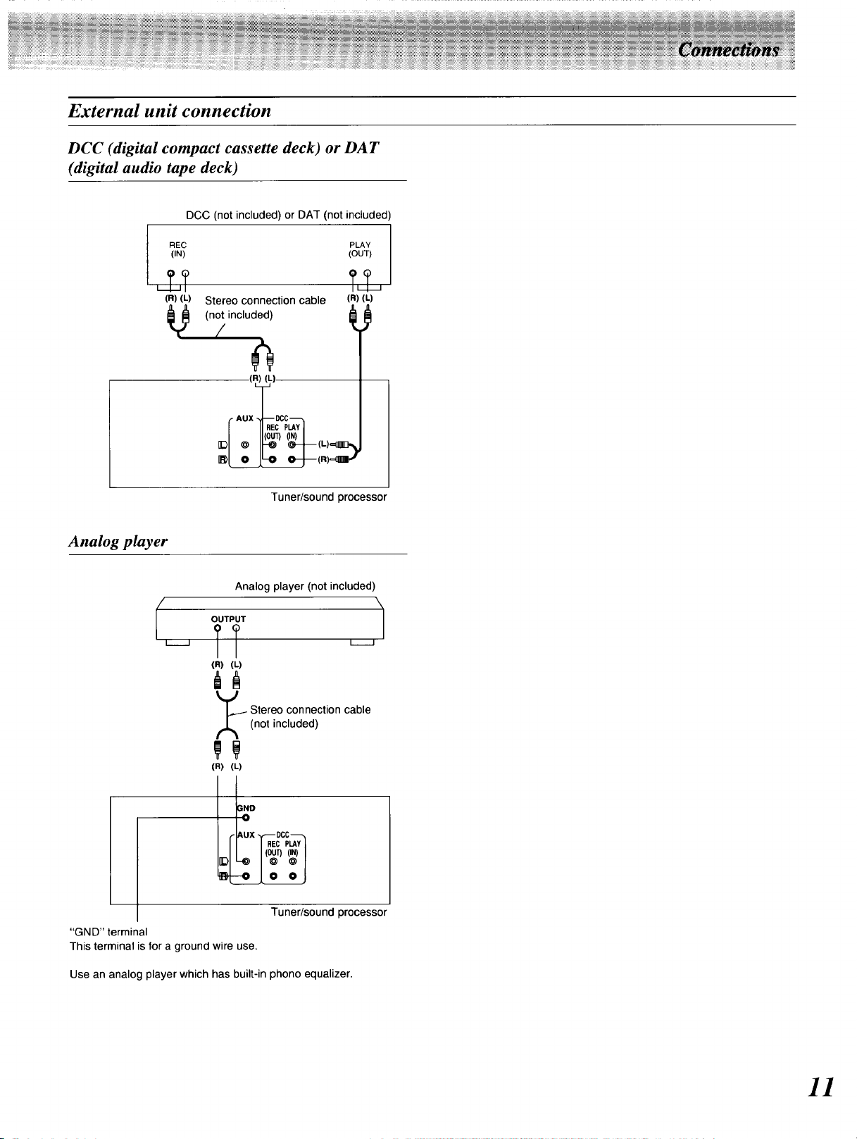
External unit connection
DCC (digital compact cassette deck) or DAT
(digital audio tape deck)
DCC (not included) or DA-r (not included)
REC
(iN)
(OUT)
PLAY 1
?&
(R) (L)
Stereo connection cable
(not included)
/
(R) (L)
, x gcc
(R) (L)
Analog player
I I
®/ o I_ _-j-(._-
Tuner/sound processor
Analog player (not included)
OUTPUT
TT
(R) (L)
_ tereo connection cable
(not included)
(R) (L)
IND
--0
AUX - _ DCC--
REC PLAY
I_ -_ © @
IR--O 0 O,
(ou (,.)I
I I
Tuner/sound processor
"GND" terminal
This terminal is for a ground wire use.
Use an analog player which has built-in phono equalizer.
11
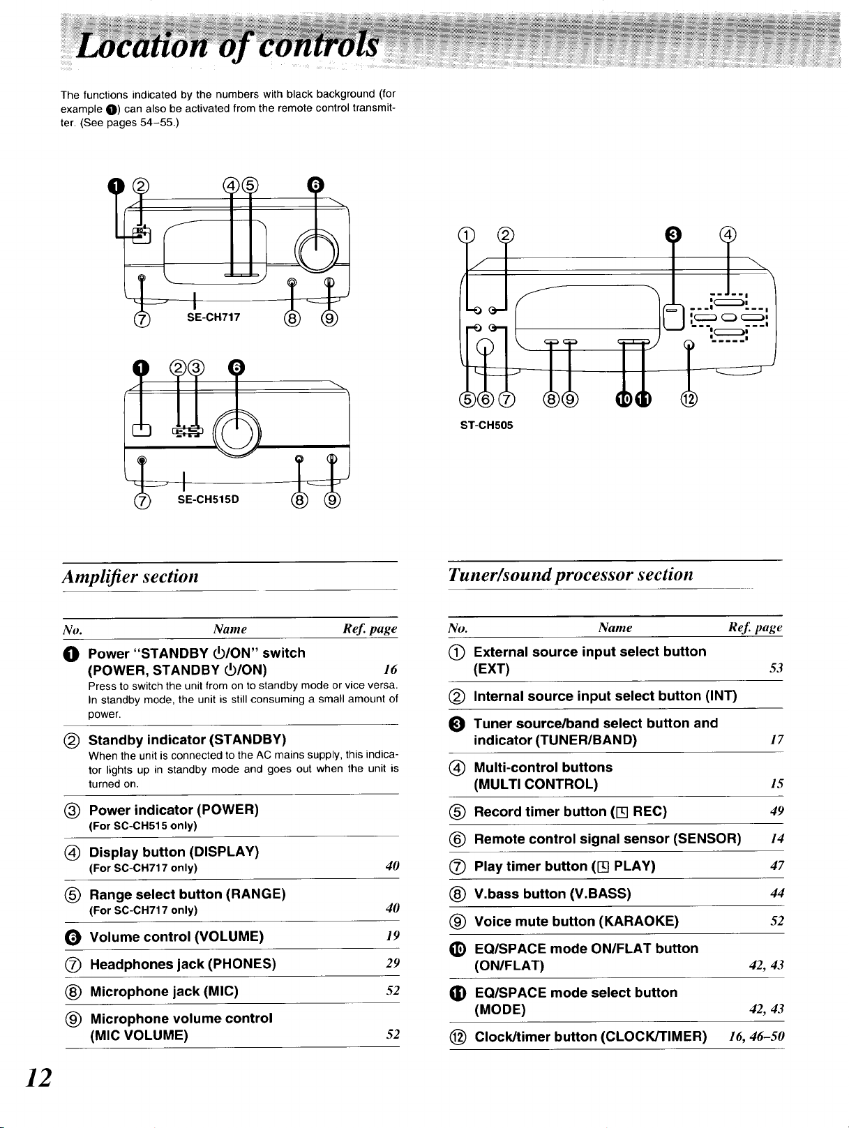
The functions indicated by the numbers with black background (for
example O) can also be activated from the remote control transmit-
ter. (See pages 54-55.)
)
II
Amplifier section
No. Name Ref. page
_D Power "STANDBY _/ON" switch
(POWER, STANDBY PO/ON) 16
Press to switch the unit from on to standby mode or vice versa.
In standby mode, the unit is still consuming a small amount of
power.
(_ Standby indicator (STANDBY)
When the unit is connected to the AC mains supply, this indica-
tor lights up in standby mode and goes out when the unit is
turned on.
(_ Power indicator (POWER)
(For SC-CH515 only)
(_) Display button (DISPLAY)
(For SC-CH717 only) 40
(_ Range select button (RANGE)
(For SC-CH717 only) 40
_) Volume control (VOLUME) 19
(_) Headphones jack (PHONES) 29
Tuner/sound processor section
No. Name ReJ_page
(_ External source input select button
(EXT) 53
(_) Internal source input select button (INT)
_1 Tuner source/band select button and
indicator (TUNER/BAND) 17
(_) Multi-control buttons
(MULTI CONTROL) 15
(_) Record timer button (I-q REC) 49
Remote control signal sensor (SENSOR) 14
(_ Play timer button (I-q PLAY) 47
V.bass button (V.BASS) 44
(_ Voice mute button (KARAOKE) 52
_) EQISPACE mode ON/FLAT button
(ON/FLAT) 42, 43
(_ Microphone jack (MIC) 52
(_) Microphone volume control
(MIC VOLUME) 52
12
G) EQ/SPACE mode select button
(MODE) 42, 43
(_) Clock/timer button (CLOCK/TIMER) 16, 46-50
z:
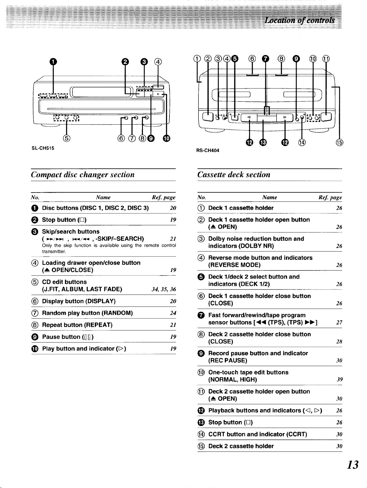
SL-CH515
Compact disc changer section
No. Name Ref. page
_0) Disc buttons (DISC 1, DISC 2, DISC 3) 20
Stop button (D) 19
_) Skip/search buttons
( ,_=-/_ , _._/_,_ ,-SKIP/-SEARCH) 21
Only the skip function is available using the remote control
transmitter.
(_ Loading drawer open/close button
(_ OPEN/CLOSE) 19
CD edit buttons
(J.FIT, ALBUM, LAST FADE) 34, 35, 36
(_ Display button (DISPLAY) 20
(_ Random play button (RANDOM) 24
Repeat button (REPEAT) 21
_) Pause button (DD) 19
_) Play button and indicator (D) /9
RS-CH404
Cassette deck section
No. Name Ref. page
(_ Deck I cassette holder 26
(_) Deck I cassette holder open button
(_ OPEN) 26
(_) Dolby noise reduction button and
indicators (DOLBY NR) 26
Reverse mode button and indicators
(REVERSE MODE) 26
_[_ Deck l/deck 2 select button and
indicators (DECK 1/2) 26
(_) Deck I cassette holder close button
(CLOSE) 26
Fast forward/rewind/tape program
sensor buttons [<1<1(TPS), (TPS) IH_] 27
(_) Deck 2 cassette holder close button
(CLOSE) 28
Record pause button and indicator
(REC PAUSE) 30
_) One-touch tape edit buttons
(NORMAL, HIGH) 39
(_ Deck 2 cassette holder open button
(_ OPEN) 30
(_) Playback buttons and indicators (<_, D) 26
_) Stop button (M) 26
(_) CCRT button and indicator (CCRT) 30
Deck 2 cassette holder 30
13
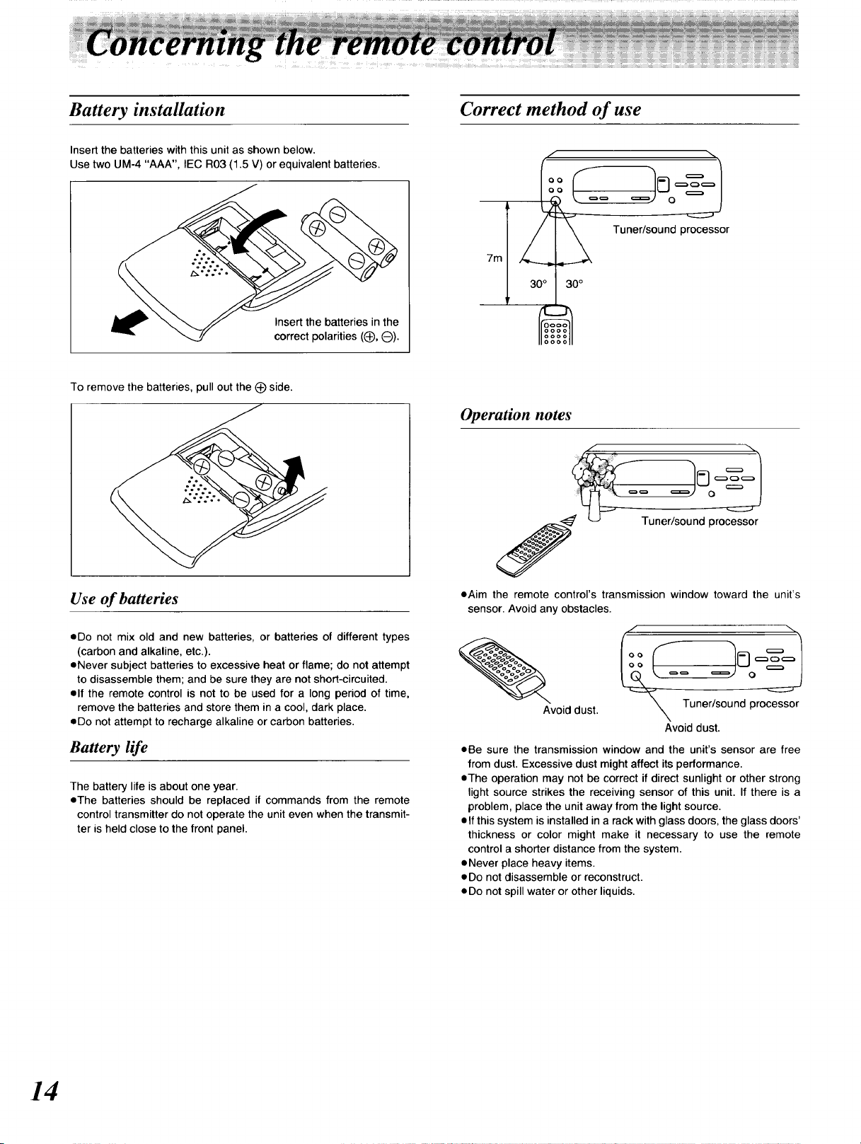
Battery installation
Insert the batteries with this unit as shown below.
Use two UM-4 "AAA", IEC R03 (1.5 V) or equivalent batteries.
Insert the batteries in the
correct polarities ((_, O).
To remove the batteries, pull out the (_)side.
Correct method of use
Tuner/sound processor
7m
30°
t
Operation notes
Use of batteries
eDo not mix old and new batteries, or batteries of different types
(carbon and alkaline, etc.).
eNever subject batteries to excessive heat or flame; do not attempt
to disassemble them; and be sure they are not short-circuited.
elf the remote control is not to be used for a long period of time,
remove the batteries and store them in a cool, dark place.
eDo not attempt to recharge alkaline or carbon batteries.
Battery life
The battery life is about one year.
eThe batteries should be replaced if commands from the remote
control transmitter do not operate the unit even when the transmit-
ter is held close to the front panel.
eAim the remote control's transmission window toward the unit's
sensor. Avoid any obstacles.
Avoid dust. _ Tuner/sound processor
Avoid dust.
eBe sure the transmission window and the unit's sensor are free
from dust. Excessive dust might affect its performance.
eThe operation may not be correct if direct sunlight or other strong
light source strikes the receiving sensor of this unit. If there is a
problem, place the unit away from the light source.
elf this system is installed in a rack with glass doors, the glass doors'
thickness or color might make it necessary to use the remote
control a shorter distance from the system.
eNever place heavy items.
• Do not disassemble or reconstruct.
eDo not spill water or other liquids.
14
Using the multi-control buttons, the following oper-
ations can be performed.
• Clock/timer settings
eTuning or presetting the radio station
eSelecting or adjusting the EQ or SPACE mode
When operating, the display shows which buttons
are available for the operation.
The chart below shows the display and the available buttons for
each operation.
For your reference:
When you press and hold V.BASS, the display will change alter-
nately showing the display example when the multi control buttons
are used.
To cancel, press any button on the system.
/
I°°
V,BASS
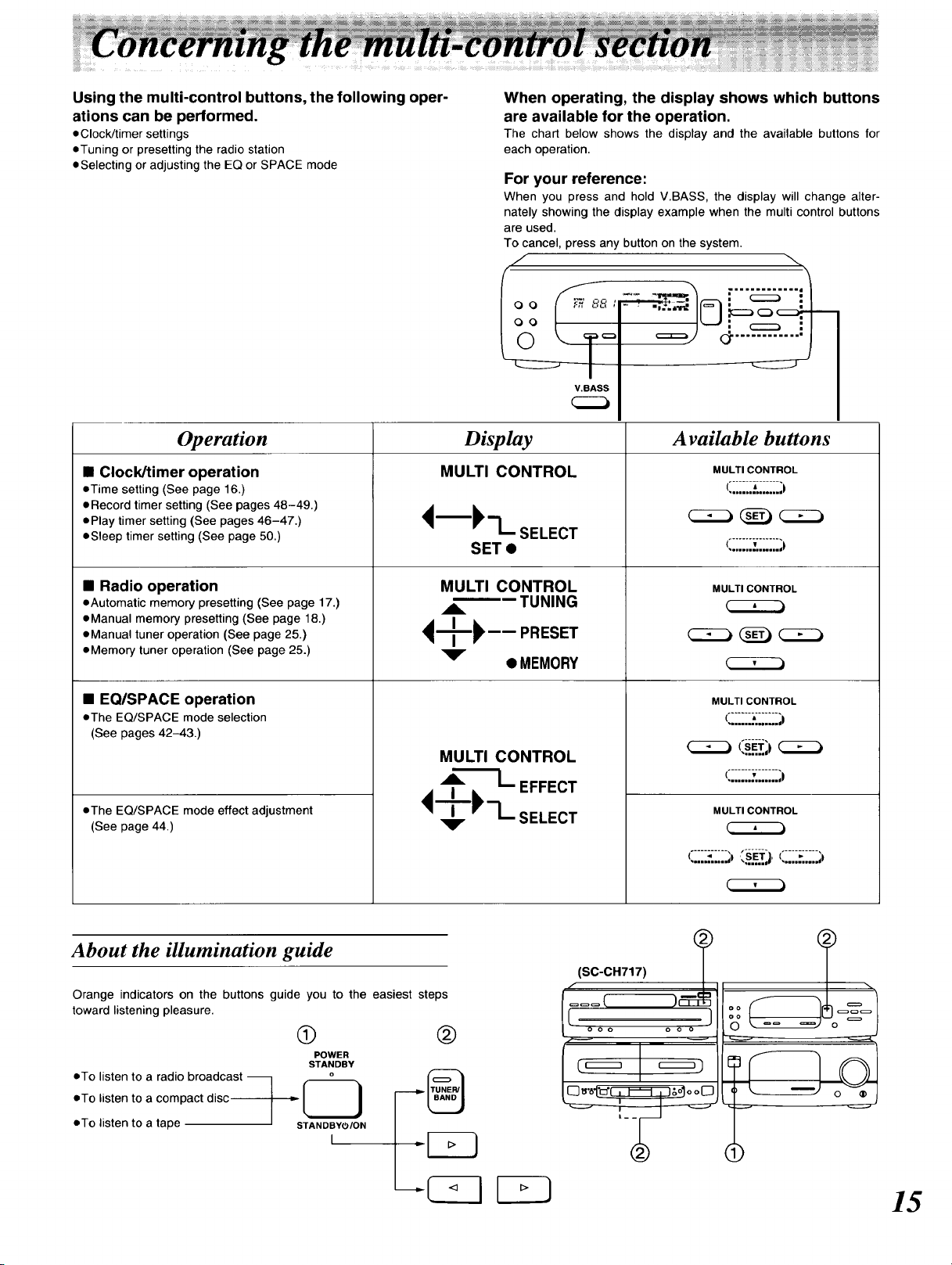
Operation
• Clock/timer operation
eTime setting (See page 16.)
eRecord timer setting (See pages 48-49.)
ePlay timer setting (See pages 46-47.)
eSleep timer setting (See page 50.)
• Radio operation
eAutomatic memory presetting (See page 17.)
eManual memory presetting (See page 18.)
eManual tuner operation (See page 25.)
eMemory tuner operation (See page 25.)
• EQ/SPACE operation
• The EQ/SPACE mode selection
(See pages 42-43.)
• The EQ/SPACE mode effect adjustment
(See page 44.)
Display
MULTI CONTROL
<Ik"L SELECT
SET •
MULTI CONTROL
_k_ TUNING
<q-i,--...s..
• MEMORY
MULTI CONTROL
Available buttons
MULTI CONTROL
(......._-.......
,o.ononon.nl)
C222_ _) _
,o.°..°.°°°o..._)
MULTI CONTROL
MULTI CONTROL
(......._-.......
,° ...... °°=iui_)
(......._-.......
,.°H°°.°°.u..€)
MULTI CONTROL
..... ._.,..,_|
About the illumination guide
Orange indicators on the buttons guide you to the easiest steps
toward listening pleasure.
®
POWER
• To listen to a radio broadcast --
eTo listen to a compact disc
eTo listen to a tape
STANDBY
STANDBY_5/ON
I
@
o oo o o o
©
o ®
15
I
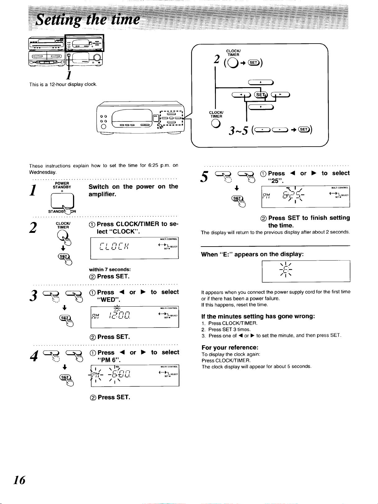
This is a 12-hour display clock.
,/ \
These instructions explain how to set the time for 6:25 p.m. on
Wednesday.
POWER
STA,OBV Switch on the power on the
S_N amplifier.
TIMER
CLOCK/
%
4,
Q Press CLOCK/TIMER to se-
lect "CLOCK".
I--I I'-I1--11 4
/._ /._ I I /._ I'1 SELECT
within 7 seconds:
@ Press SET,
F
CLOCK/
TIMER
2 (0.,
CLOCK/
TIMER
O
3-5
(_ Press 41 or • to select
"25".
I--. "-/I-- 4"---I'-L.SE_Ec_
_,1/
_F._
/t .%
/1",_
' 111:"_l/ ............
(_) Press SET to finish setting
the time.
The display will return to the previous display after about 2 seconds.
When "E:" appears on the display:
(DPress "< or • to select
"WED".
I I'._'./.I/_l. S_LECT
(_ Press SET.
4 _ _ (_Press <1 or • to select
"PM 6".
F';I- "-"-' '-' _-
-- f._'l.'l'l /._1. _SELECT
i_ /i %
(_) Press SET.
It appears when you connect the power supply cord for the first time
or if there has been a power failure.
If this happens, reset the time.
If the minutes setting has gone wrong:
1. Press CLOCK/TIMER.
2. Press SET 3 times.
3. Press one of _1or • to set the minute, and then press SET.
For your reference:
To display the clock again:
Press CLOCK/TIMER.
The clock display will appear for about 5 seconds.
16
This feature allows you to set broadcast frequencies into the mem-
ory. You can then easily retrieve any of those broadcast frequencies
by pressing • or II,, on the tuner/sound processor.
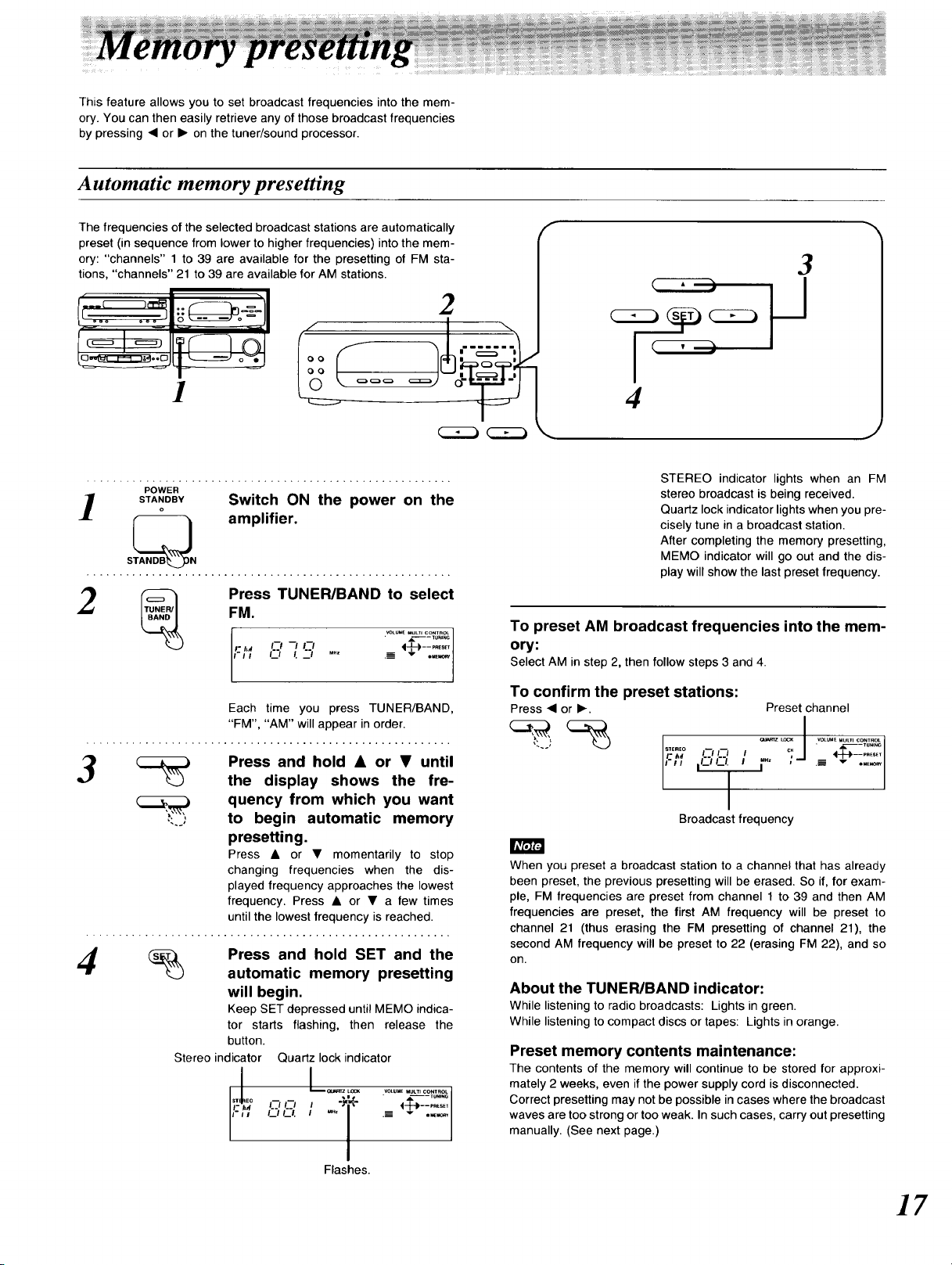
Automatic memory presetting
The frequencies of the selected broadcast stations are automatically
preset (in sequence from lower to higher frequencies) into the mem-
ory: "channels" 1 to 39 are available for the presetting of FM sta-
tions, "channels" 21 to 39 are available for AM stations.
2
1
POWER
S_ANoOBY Switch ON the power on the
S_N amplifier.
Press TUNER/BAND to select
FM.
'/; .................
Each time you press TUNER/BAND,
"FM", "AM" will appear in order.
F
3
4
STEREO indicator lights when an FM
stereo broadcast is being received.
Quartz lock indicator lights when you pre-
cisely tune in a broadcast station.
After completing the memory presetting,
MEMO indicator will go out and the dis-
play will show the last preset frequency.
To preset AM broadcast frequencies into the mem-
ory:
Select AM in step 2, then follow steps 3 and 4.
To confirm the preset stations:
Press • or I_. Preset channel
3
Press and hold • or • until
the display shows the fre-
quency from which you want
,- : to begin automatic memory
presetting.
Press • or • momentarily to stop
changing frequencies when the dis-
played frequency approaches the lowest
frequency. Press • or • a few times
until the lowest frequency is reached.
_ Press and hold SET and the
automatic memory presetting
will begin.
Keep SET depressed until MEMO indica-
tor starts flashing, then release the
button.
Stereo indicator Quartz lock indicator
Flashes.
s,.,,EoII-'llIlll_.l. II I"" ; .-= I-+-_,..........,,_
Broadcast frequency
Ir_t;'J3F3
When you preset a broadcast station to a channel that has already
been preset, the previous presetting will be erased. So if, for exam-
ple, FM frequencies are preset from channel 1 to 39 and then AM
frequencies are preset, the first AM frequency will be preset to
channel 21 (thus erasing the FM presetting of channel 21), the
second AM frequency will be preset to 22 (erasing FM 22), and so
on.
About the TUNER/BAND indicator:
While listening to radio broadcasts: Lights in green.
While listening to compact discs or tapes: Lights in orange.
Preset memory contents maintenance:
The contents of the memory will continue to be stored for approxi-
mately 2 weeks, even if the power supply cord is disconnected.
Correct presetting may not be possible in cases where the broadcast
waves are too strong or too weak. In such cases, carry out presetting
manually. (See next page.)
17
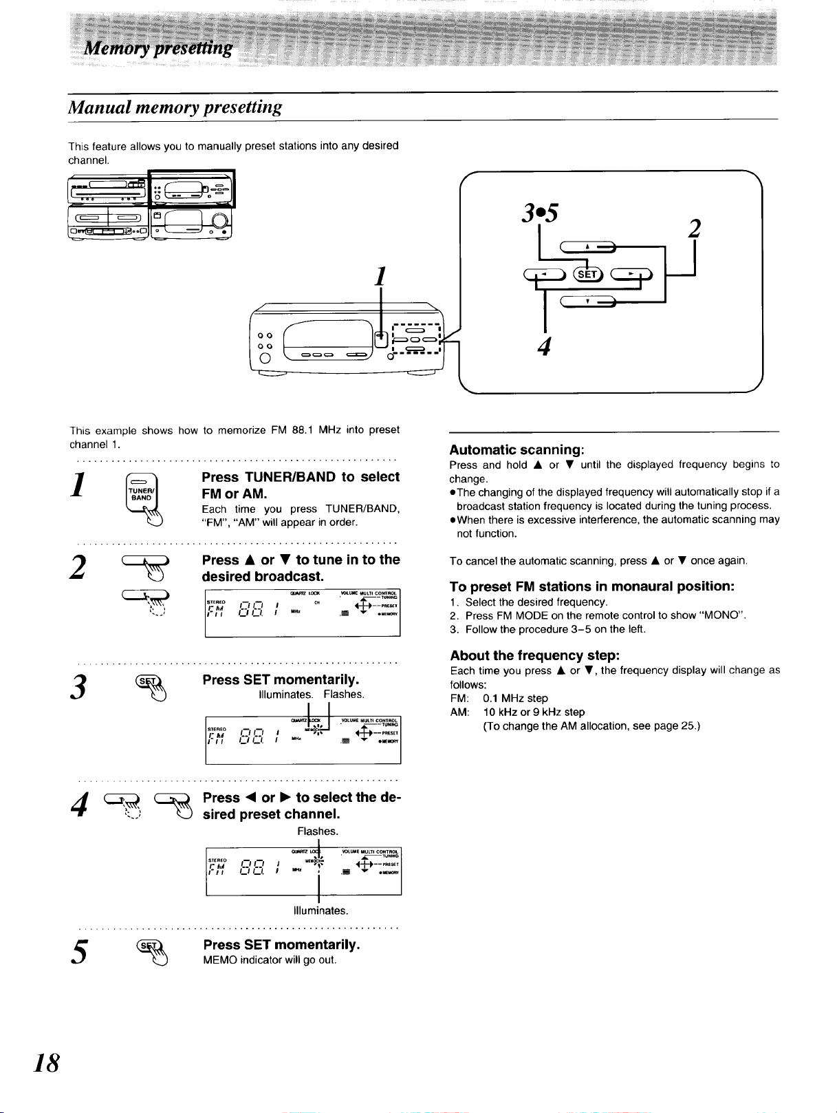
Manual memory presetting
This feature allows you to manually preset stations into any desired
channel•
o_ -_:
1
This example shows how to memorize FM 88.1 MHz into preset
channel 1.
FM or AM.
_ Press TUNER/BAND to select
Each time you press TUNER/BAND,
"FM", "AM" will appear in order.
3.5
2
4
Automatic scanning:
Press and hold • or • until the displayed frequency begins to
change.
eThe changing of the displayed frequency will automatically stop ifa
broadcast station frequency is located during the tuning process.
eWhen there is excessive interference, the automatic scanning may
not function.
2
3
Press • or • to tune in to the
desired broadcast.
• _- TUN*NG
_LUME MULTi CONTROL I
Press SET momentarily.
".-'"°° o,-, , *%
,,; :??:2
Press <1 or • to select the de-
sired preset channel.
,,,.Eo f--/ I'--/ t .s._c_ 4 i____ p.Ese,
Illuminates. Flashes,
-- , |, ----PRESET
Flashes.
"": I ...............
Illuminates.
% Press SET momentarily.
MEMO indicator will go out.
To cancel the automatic scanning, press • or • once again.
To preset FM stations in monaural position:
1. Select the desired frequency.
2. Press FM MODE on the remote control to show "MONO".
l
3. Follow the procedure 3-5 on the left.
About the frequency step:
Each time you press • or •, the frequency display will change as
follows:
FM: 0.1 MHz step
AM: 10 kHz or 9 kHz step
(To change the AM allocation, see page 25.)
18
 Loading...