


The illustration shows SC-HT740.
Operating Instructions
DVD Home Theater Sound System
Model No. SC-HT740/SC-HT940/
SC-HT743
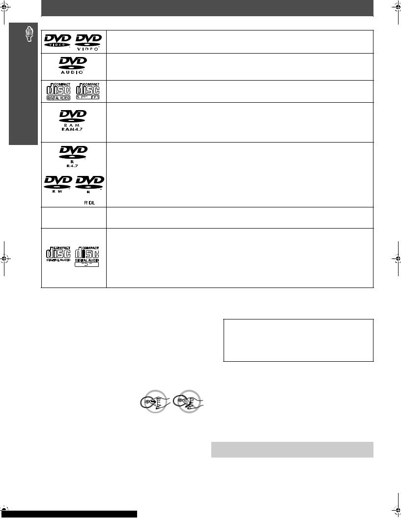
Region number
The player plays DVD-Video marked with labels containing the region number “1” or “ALL”.
Example:
1 ALL 124
[U.S.A.[and[Canada[
As an ENERGY STAR® Partner, Panasonic has determined that
this product meets the ENERGY STAR® guidelines for energy efficiency.
§For Canada only: The word “Participant” is used in place of the word “Partner”.
P 
 PC
PC 
 PX
PX
|
|
|
|
|
|
|
|
|
|
|
|
|
|
|
|
|
|
|
|
|
|
|
|
|
|
|
|
|
|
|
|
|
|
|
|
|
|
|
|
|
|
|
|
|
|
|
|
|
|
|
|
|
|
|
|
|
|
|
|
|
|
|
|
|
|
|
|
|
|
|
|
|
|
|
|
|
|
|
|
|
|
|
|
|
|
|
|
|
|
|
|
|
|
High-quality |
|
8 |
||||||||
|
|
|
|
|
picture |
page |
||||||||
|
|
|
|
HDMI capability, Advanced |
|
|
||||||||
|
|
|
|
|
progressive scan and more. |
|
|
|||||||
|
|
|
|
|
|
|
|
|
||||||
|
|
|
|
|
U.S.A. and Canada |
-ready |
|
|
||||||
|
|
|
|
|
Wireless |
|
8 |
|||||||
|
|
|
|
|
surround sound |
page |
||||||||
|
|
|
|
Optional wireless surround |
|
|
||||||||
|
|
|
|
|
speaker connection. |
|
|
|||||||
|
|
|
|
High-performance |
page 28 |
|||||||||
|
|
|
|
|
sound effects |
|||||||||
Sound quality enhancement,
Bass enhancement and more.
Before connecting, operating or adjusting this product, please read the instructions completely.
Please keep this manual for future reference.
If you have any questions contact
In the U.S.A.: 1-800-211-PANA (7262) In Canada: 1-800-561-5505
RQT8582-4P
IMPORTANT SAFETY INSTRUCTIONS
Dear customer
Thank you for purchasing this product. For optimum performance and safety, please read these instructions carefully.
≥These operating instructions are applicable to models SC-HT740, SC-HT743 and SC-HT940 for a variety of regions.
≥Unless otherwise indicated, illustrations in these operating instructions are of SC-HT740 for U.S.A. and Canada.
≥Operations in these instructions are described mainly with the remote control, but you can perform the operations on the main unit if the controls are the same.
[HT740]: indicates features applicable to SC-HT740 only. [HT743]: SC-HT743 only.
[HT940]: SC-HT940 only.
System |
SC-HT740 |
SC-HT743 |
SC-HT940 |
Main unit |
SA-HT740 |
SA-HT743 |
SA-HT940 |
|
|
|
|
Front speakers |
SB-FS740 |
SB-FS740 |
SB-FS940 |
|
|
|
|
Center speaker |
SB-PC740 |
SB-PC740 |
SB-PC940 |
|
|
|
|
Surround speakers |
SB-FS741 |
SB-FS741 |
SB-FS941 |
|
|
|
|
Subwoofer |
SB-W740 |
SB-W740 |
SB-W940 |
|
|
|
|
CAUTION!
THIS PRODUCT UTILIZES A LASER.
USE OF CONTROLS OR ADJUSTMENTS OR PERFORMANCE OF PROCEDURES OTHER THAN THOSE SPECIFIED HEREIN MAY RESULT IN HAZARDOUS RADIATION EXPOSURE.
DO NOT OPEN COVERS AND DO NOT REPAIR YOURSELF. REFER SERVICING TO QUALIFIED PERSONNEL.
WARNING:
TO REDUCE THE RISK OF FIRE, ELECTRIC SHOCK OR PRODUCT DAMAGE, DO NOT EXPOSE THIS APPARATUS TO RAIN, MOISTURE, DRIPPING OR SPLASHING AND THAT NO OBJECTS FILLED WITH LIQUIDS, SUCH AS VASES, SHALL BE PLACED ON THE APPARATUS.
THE FOLLOWING APPLIES ONLY IN THE U.S.A.
FCC Note:
This equipment has been tested and found to comply with the limits for a Class B digital device, pursuant to Part 15 of the FCC Rules. These limits are designed to provide reasonable protection against harmful interference in a residential installation. This equipment generates, uses and can radiate radio frequency energy and, if not installed and used in accordance with the instructions, may cause harmful interference to radio communications. However, there is no guarantee that interference will not occur in a particular installation. If this equipment does cause harmful interference to radio or television reception, which can be determined by turning the equipment off and on, the user is encouraged to try to correct the interference by one or more of the following measures:
≥Reorient or relocate the receiving antenna.
≥Increase the separation between the equipment and receiver.
≥Connect the equipment into an outlet on a circuit different from that to which the receiver is connected.
≥Consult the dealer or an experienced radio/TV technician for help.
Any unauthorized changes or modifications to this equipment would void the user’s authority to operate this device.
This device complies with Part 15 of the FCC Rules. Operation is subject to the following two conditions: (1) This device may not cause harmful interference, and (2) this device must accept any interference received, including interference that may cause undesired operation.
Responsible Party:
Panasonic Corporation of North America
One Panasonic Way
Secaucus, NJ 07094
Telephone No.: 1-800-211-7262
CAUTION!
≥DO NOT INSTALL OR PLACE THIS UNIT IN A BOOKCASE, BUILT-IN CABINET OR IN ANOTHER CONFINED SPACE. ENSURE THE UNIT IS WELL VENTILATED. TO PREVENT RISK OF ELECTRIC SHOCK OR FIRE HAZARD DUE TO OVERHEATING, ENSURE THAT CURTAINS AND ANY OTHER MATERIALS DO NOT OBSTRUCT THE VENTILATION VENTS.
≥DO NOT OBSTRUCT THE UNIT’S VENTILATION OPENINGS WITH NEWSPAPERS, TABLECLOTHS, CURTAINS, AND SIMILAR ITEMS.
≥DO NOT PLACE SOURCES OF NAKED FLAMES, SUCH AS LIGHTED CANDLES, ON THE UNIT.
≥DISPOSE OF BATTERIES IN AN ENVIRONMENTALLY FRIENDLY MANNER.
The socket outlet shall be installed near the equipment and easily accessible. The mains plug of the power supply cord shall remain readily operable.
To completely disconnect this apparatus from the AC Mains, disconnect the power supply cord plug from AC receptacle.
THE FOLLOWING APPLIES ONLY IN THE U.S.A. AND CANADA
CAUTION
RISK OF ELECTRIC SHOCK
DO NOT OPEN
CAUTION: TO REDUCE THE RISK OF ELECTRIC SHOCK, DO NOT REMOVE SCREWS. NO USER-SERVICEABLE PARTS INSIDE. REFER SERVICING TO QUALIFIED SERVICE PERSONNEL.
The lightning flash with arrowhead symbol, within an equilateral triangle, is intended to alert the user to the presence of uninsulated “dangerous voltage” within the product’s enclosure that may be of sufficient magnitude to constitute a risk of electric shock to persons.
The exclamation point within an equilateral triangle is intended to alert the user to the presence of important operating and maintenance (servicing) instructions in the literature accompanying the appliance.
RQT8582
2
IMPORTANT SAFETY INSTRUCTIONS
Read these operating instructions carefully before using the unit. Follow the safety instructions on the unit and the applicable safety instructions listed below. Keep these operating instructions handy for future reference.
1)Read these instructions.
2)Keep these instructions.
3)Heed all warnings.
4)Follow all instructions.
5)Do not use this apparatus near water.
6)Clean only with dry cloth.
7)Do not block any ventilation openings. Install in accordance with the manufacturer’s instructions.
8)Do not install near any heat sources such as radiators, heat registers, stoves, or other apparatus (including amplifiers) that produce heat.
9)\U.S.A.\and\Canada]
Do not defeat the safety purpose of the polarized or grounding-type plug. A polarized plug has two blades with one wider than the other. A grounding-type plug has two blades and a third grounding prong. The wide blade or the third prong are provided for your safety. If the provided plug does not fit into your outlet, consult an electrician for replacement of the obsolete outlet.
10)Protect the power cord from being walked on or pinched particularly at plugs, convenience receptacles, and the point where they exit from the apparatus.
11)Only use attachments/accessories specified by the manufacturer.
12)Use only with the cart, stand, tripod, bracket, or table
specified by the manufacturer, or sold with the apparatus. When a cart is used, use caution when moving the cart/apparatus combination to avoid injury from tip-over.
13) Unplug this apparatus during lightning storms or when unused for long periods of time.
14)Refer all servicing to qualified service personnel. Servicing is required when the apparatus has been damaged in any way, such as powersupply cord or plug is damaged, liquid has been spilled or objects have fallen into the apparatus, the apparatus has been exposed to rain or moisture, does not operate normally, or has been dropped.
TABLE OF CONTENTS |
|
||
|
IMPORTANT SAFETY INSTRUCTIONS . . . . . . . |
2 |
|
Getting |
Simple Setup |
|
|
Started |
STEP 1 |
Assembling the front speakers . . . . |
4 |
|
|
Speaker installation options . . . . . . . . . . . . . |
6 |
|
STEP 2 |
Positioning the speakers . . . . . . . . . |
7 |
|
STEP 3 |
Speaker connections . . . . . . . . . . . . . |
8 |
|
STEP 4 |
Audio and video connections. . . . . . |
8 |
|
|
Television with an HDMI terminal . . . . . . . . . |
8 |
|
|
Basic audio connection. . . . . . . . . . . . . . . . . |
9 |
|
|
Basic video connection. . . . . . . . . . . . . . . . . |
9 |
STEP 5 Radio and AC cord connections . . . . 10
STEP 6 Preparing the remote control . . . . 10
STEP 7 Performing QUICK SETUP . . . . . . 11
Control reference guide . . . . . . . . . . . . . . . . . 11 Discs that can be played. . . . . . . . . . . . . . . . . 12 Disc caution . . . . . . . . . . . . . . . . . . . . . . . . . . . 12 Maintenance. . . . . . . . . . . . . . . . . . . . . . . . . . . 12 Product Service . . . . . . . . . . . . . . . . . . . . . . . . 13 Glossary . . . . . . . . . . . . . . . . . . . . . . . . . . . . . . 13
Playing
Discs
Basic play. . . . . . . . . . . . . . . . . . . . . . . . . . . . . . 14
Using the main unit. . . . . . . . . . . . . . . . . . . . . . . . . . . 14 Using the remote control . . . . . . . . . . . . . . . . . . . . . . 15
Convenient functions . . . . . . . . . . . . . . . . . . . . 16
Checking the disc type in each tray . . . . . . . . . . . . . . 16 Displaying current playback condition. . . . . . . . . . . . . 16 Playing CDs sequentially . . . . . . . . . . . . . . . . . . . . . . 16 Changing the zoom ratio. . . . . . . . . . . . . . . . . . . . . . . 16 Repeat play. . . . . . . . . . . . . . . . . . . . . . . . . . . . . . . . . 16 Program and Random play. . . . . . . . . . . . . . . . . . . . . 17
Playing data discs using navigation menus . . . 18
Playing data discs . . . . . . . . . . . . . . . . . . . . . . . . . . . 18 Selecting a track using CD text . . . . . . . . . . . . . . . . . 18 Playing HighMATTM discs . . . . . . . . . . . . . . . . . . . . . . 19 Playing RAM and DVD-R/-RW (DVD-VR) discs . . . . . 19
Using on-screen menus . . . . . . . . . . . . . . . . . . 20
Main menu . . . . . . . . . . . . . . . . . . . . . . . . . . . . . . . . . 20 Other Settings . . . . . . . . . . . . . . . . . . . . . . . . . . . . . . 21
Changing the player settings . . . . . . . . . . . . . . 23
Changing the delay time of the speakers. . . . . . . . . . 25
Other
Operations
Using the radio . . . . . . . . . . . . . . . . . . . . . . . . . 26
Presetting stations automatically . . . . . . . . . . . . . . . . 26 Selecting the preset channels . . . . . . . . . . . . . . . . . . 26 Manual tuning . . . . . . . . . . . . . . . . . . . . . . . . . . . . . . . 26 Using an outdoor antenna (optional) . . . . . . . . . . . . . 27
Using sound effects . . . . . . . . . . . . . . . . . . . . . 28
Changing the sound quality: Sound Field Control . . . 28 Enhancing the sound from the center speaker:
Center Focus . . . . . . . . . . . . . . . . . . . . . . . . . . . . . . 28 Enhancing the stereo sound: Dolby Pro Logic II . . . . 28 [HT940] Enhancing the surround sound effect:
Surround Enhancer. . . . . . . . . . . . . . . . . . . . . . . . . 28 Enhancing the bass sound: H.BASS . . . . . . . . . . . . . 29 Adjusting the amount of bass: Subwoofer level . . . . . 29
Adjusting the volume of each speaker:
Speaker level adjustments . . . . . . . . . . . . . . . . . . . 29
Operating other equipment . . . . . . . . . . . . . . . 30
Operating the television . . . . . . . . . . . . . . . . . . . . . . . 30 Changing the remote control code. . . . . . . . . . . . . . . 30 [HT940] Operating both the television and
the home theater system: Control with HDMI
(HDAVI ControlTM) . . . . . . . . . . . . . . . . . . . . . . . . . . . 30
Using other useful functions . . . . . . . . . . . . . . 31
Setting the sleep timer . . . . . . . . . . . . . . . . . . . . . . . . 31 Muting the sound . . . . . . . . . . . . . . . . . . . . . . . . . . . . 31 Using headphones. . . . . . . . . . . . . . . . . . . . . . . . . . . 31 Using the Music Port . . . . . . . . . . . . . . . . . . . . . . . . . 31
Troubleshooting guide . . . . . . . . . . . . . . . . . . . 32
Specifications . . . . . . . . . . . . . . . . . . . . . . . . . . 35
Reference
Limited Warranty (ONLY FOR U.S.A.) . . . . . . . 37
Limited Warranty (ONLY FOR CANADA). . . . . 38  Accessories . . . . . . . . . . . . . . . . . . . . Back cover
RQT8582
3
Simple Setup
STEP1 Assembling the front speakers |
The supplied stands are specially designed for |
front speakers. Use only as indicated in this setup. |
|
|
attachment to Panasonic SB-FS740 or SB-FS940 |
Preparation
≥To prevent damage or scratches, lay down a soft cloth and perform assembly on it.
≥For assembly, use a Phillips-head screwdriver.
≥Make sure you have all the indicated components before starting assembly, setup, and connection.
≥There is no difference between the right and left speakers and stands.
≥For optional wall mount, refer to page 6.
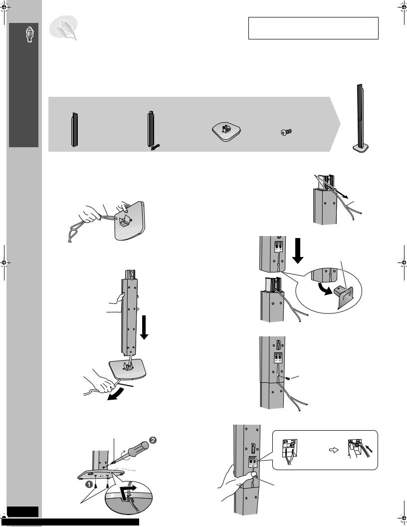
[HT740] [HT743]
2 Front speakers |
2 Stands |
2 Bases |
8 Screws |
(with cover plate) |
(with cable) |
|
|
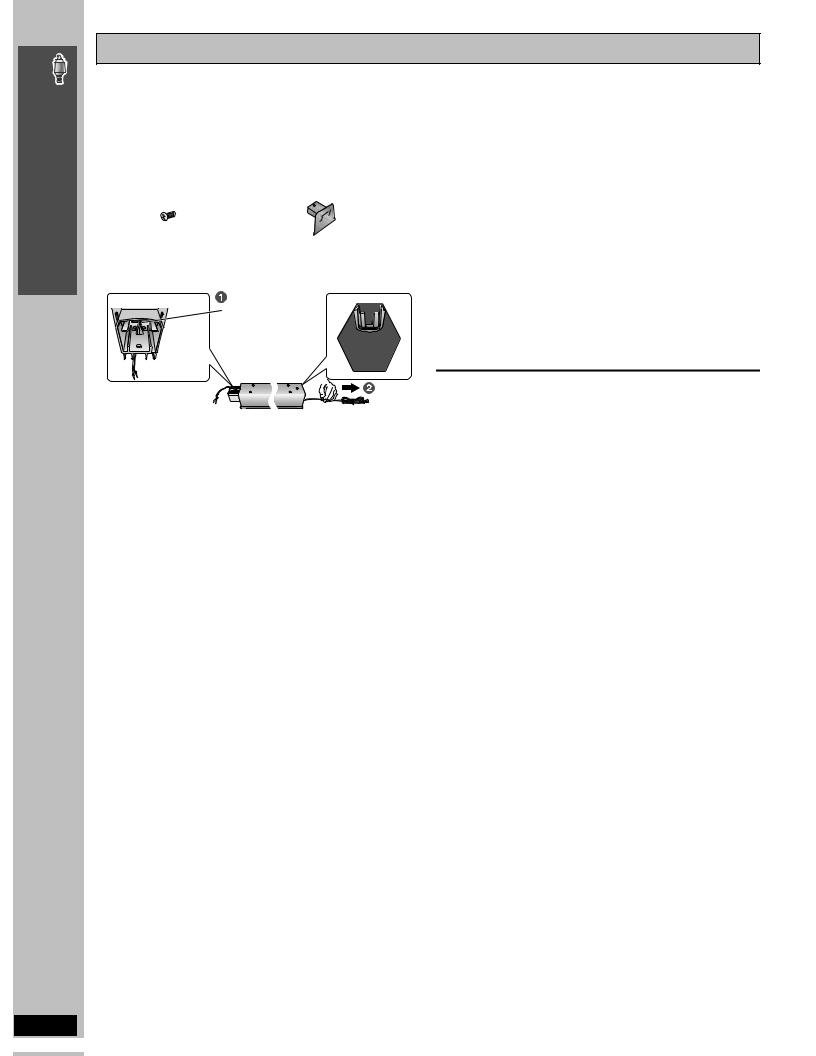
Assembling the front speakers
1 Attach the stand to the base.
1Thread the speaker cable through the base.
For quicker threading, loosely fold the cable in half (do not crease), pass the folded portion through the hole, and then pull the rest of the cable through the base.
Cable
Base
2Attach the stand to the base while gently pulling on the end of the speaker cable.
 Stand
Stand
3
4
Attach the speaker to the stand.
1 Pull out the end of |
Ridges |
|
the speaker cable |
||
|
||
and position it |
|
|
between the ridges. |
|
|
|
Cable |
|
|
Stand |
|
2 Attach the speaker to the stand. |
||
|
Cover plate |
|
Speaker |
Remove before attaching |
|
|
the speaker and keep for |
|
|
wall-mount use ( page 6). |
|
Stand
Secure the speaker to the stand.
RQT8582
4
|
Speaker |
|
Base |
|
|
|
|
Screw |
Cable |
|
Tighten securely. |
Stand |
Ensure the speaker cable is |
|
Pull gently. |
centered in the groove. |
2 Secure the stand to the base. |
5 Connect the speaker cable. |
Screw |
|
Tighten securely. |
Insert the wire fully. |
|
_: White |
Stand |
`: Blue |
|
Push! |
Base |
|
|
Press the speaker cable |
Slide the speaker |
into the groove. |
cable into the groove. |
|
Screws |
|
Tighten securely. |
|
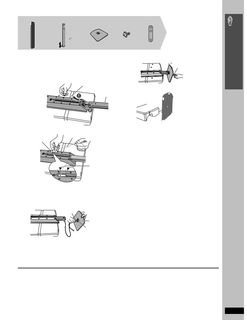
[HT940]
2 Front speakers 2 Stands (with cable) |
2 Bases |
6 Screws |
2 Sliders |
The speaker height can be adjusted.
Min: 110 cm (431/4z)
Max: 135 cm (535/32z)
1 Attach the speaker to the stand.
Place the polyfoam underneath the speaker for stability while attaching the speaker to the stand.
1Feed the speaker cable (the shorter part) into the bottom of the speaker and through the slot at the rear.
2While pulling the speaker cable up through the slot, slide the speaker stand into the bottom of the speaker.
Cable
3
Speaker
Stand
Polyfoam |
|
3 Thread the cable through the middle hole of the slider and |
4 |
fasten the slider with the two screws. Cable
Slider
Screws |
Tighten securely. 5
2 Attach the stand to the base.
1Thread the speaker cable through the base.
For quicker threading, loosely fold the cable in half (do not crease), pass the folded portion through the hole, and then pull the rest of the cable through the base.
Cable
Rounded side |
6 |
Large hole
Base
2Insert the stand into the base while gently pulling on the end of the cable.
 Cable
Cable
Secure the stand to the base.

 Screw
Screw
Tighten securely.
Adjust the speaker height.
1 |
Loosen the screws until |
|
|
the speaker can slide up |
|
|
and down the stand. |
Phillips-head |
2 |
Raise the speaker to the |
|
|
desired height, and then |
screwdriver |
|
re-tighten the screws . |
|
Connect the speaker cable.
Insert the wire fully.
_: White
`: Blue
Push!
Press the speaker cable into the groove.
Push excess cable back through the slider holder.
Secure the speaker cable to the base.
Slide the cable
into the groove.
Cable
Simple Setup
Assembling the front speakers
∫ Preventing the speakers from falling |
e.g. [HT740] [HT743] |
≥You will need to obtain the appropriate screw eyes to match the |
|
walls or pillars to which they are going to be fastened. |
|
≥Consult a qualified housing contractor concerning the |
|
appropriate procedure when attaching to a concrete wall or a |
|
surface that may not have strong enough support. Improper |
|
attachment may result in damage to the wall or speakers. |
|
|
Rear of the speaker |
String (not included)
Thread from the wall to the speaker and tie tightly.
|
|
Approx. |
|
Screw eye |
Wall |
150 mm |
|
(not included) |
(529/32z) |
||
|
RQT8582
5
Simple Setup
Assembling the front speakers
Speaker installation options
∫ Attaching to a wall
You can attach all of the speakers (except subwoofer) to a wall.
≥The wall or pillar on which the speakers are to be attached should be capable of supporting over 10 kg (22 lbs) [[HT940] 15 kg (33 lbs) for the front speakers] per screw. Consult a qualified building contractor when attaching the speakers to a wall. Improper attachment may result in damage to the wall and speakers.
≥When mounting the front speakers to a wall, we recommend using a string (not included) to prevent it from falling.
2 Screws [HT740] [HT743] |
2 Cover plates [HT740] [HT743] |
|
|
Preparation for front speakers
[HT740] [HT743]
1 Remove the speaker cable from the stand.
Release the cable from the groove.
2 Connect the cable ( page 4).
[HT940]
1 Pull down the longer part
of the cable to release 

 the cable from the groove


 inside the stand, and
then pull the speaker cable out from the stand.
2 Feed the cable into the bottom of the speaker and through the slot at the rear.
3 Connect the cable ( page 5).
1 [HT740] [HT743] Attach the cover plate to the front speaker.
Cover plate |
Screw |
Tighten securely.
Front speaker |
[HT940] |
Center speaker |
[HT940] |
|
255 mm |
|
|
190 mm |
|
(101/16z) |
|
|
|
|
|
|
|
(715/32z) |
|
|
|
|
Surround speaker [HT940] |
|
|
320 mm |
|
|
|
|
(1219/32z) |
|
|
|
e.g. |
In this position, the |
Move the speaker |
||
|
speaker will likely |
so that the screw |
||
|
fall if moved to the |
is in this position. |
||
|
left or right. |
|
|
|
Reattaching the speaker cable to the stand |
|
|
[HT740] [HT743] |
|
|
1 |
Remove the eight screws |
Screw |
|
from the stand, and remove |
|
|
the speaker net. |
|
2 |
Position the cable. |
|
Press the cable into the groove.
Approx.
15 cm Cable
(529/32z)
3 Attach the speaker net with the screws.
[HT940]
1 Remove the two screws from the stand, and remove the metal cover.
Screw |
Screw |
Metal cover
Plastic cover 
2Pull the cable out about 40 cm (153/4z) from the hole in the metal cover, and insert the plastic cover.
2 Drive a screw (not included) into the wall.
|
|
|
|
|
|
|
‰7.5 to 9.5 mm |
‰4.0 mm (5/32q) |
|
|
|
|
|
||
|
|
|
|
|
|||
|
|
|
|
|
(19/64q to 3/8q) |
||
Wall or pillar |
|
|
|
|
|||
|
|
|
|
|
|||
|
|
5.0 to 7.0 mm (3/16q to 9/32q) |
|||||
Approx. 40 cm (153/4z)
3 Insert the metal cover so it does not disturb the cable and close
tightly with the two screws.
∫ Fitting speaker stands (not included)
3 Fit the speaker securely onto the screw(s) with the hole(s).
Front speaker [HT740] [HT743] Center speaker [HT740] [HT743]
106 mm |
|
|
(43/16z) |
|
|
|
200 mm |
|
|
(77/8z) |
|
340 mm |
|
|
(133/8z) |
Surround speaker |
[HT740][HT743] |
|
||
RQT8582 |
|
|
6
(Except front speakers)
Ensure the stands meet these conditions before purchasing them. Note the diameter and length of the screws and the distance between screws as shown in the diagram.
≥The stands must be able to support over 10 kg (22 lbs).
≥The stands must be stable even if the speakers are in a high position.
e.g. Center speaker [HT740] [HT743]
Metal screw holes
For attaching to speaker stands
5 mm (3/16q), pitch 0.8 mm (1/32q)
Plate thickness plus 7 mm |
|
to 10 mm (plus 9/32q to 13/32q) |
60 mm (23/8q) |
Speaker stand (not included)
STEP2 Positioning the speakers
How you set up your speakers can affect the bass and the sound field. Note the following points:
≥Place speakers on flat secure bases.
≥Placing speakers too close to floors, walls, and corners can result in excessive bass. Cover walls and windows with thick curtains.
≥Left and right speakers are interchangeable, but front and surround speakers are not.
FRONT |
SURROUND |
CENTER |
SUBWOOFER |
(L, R) |
(L, R) |
|
|
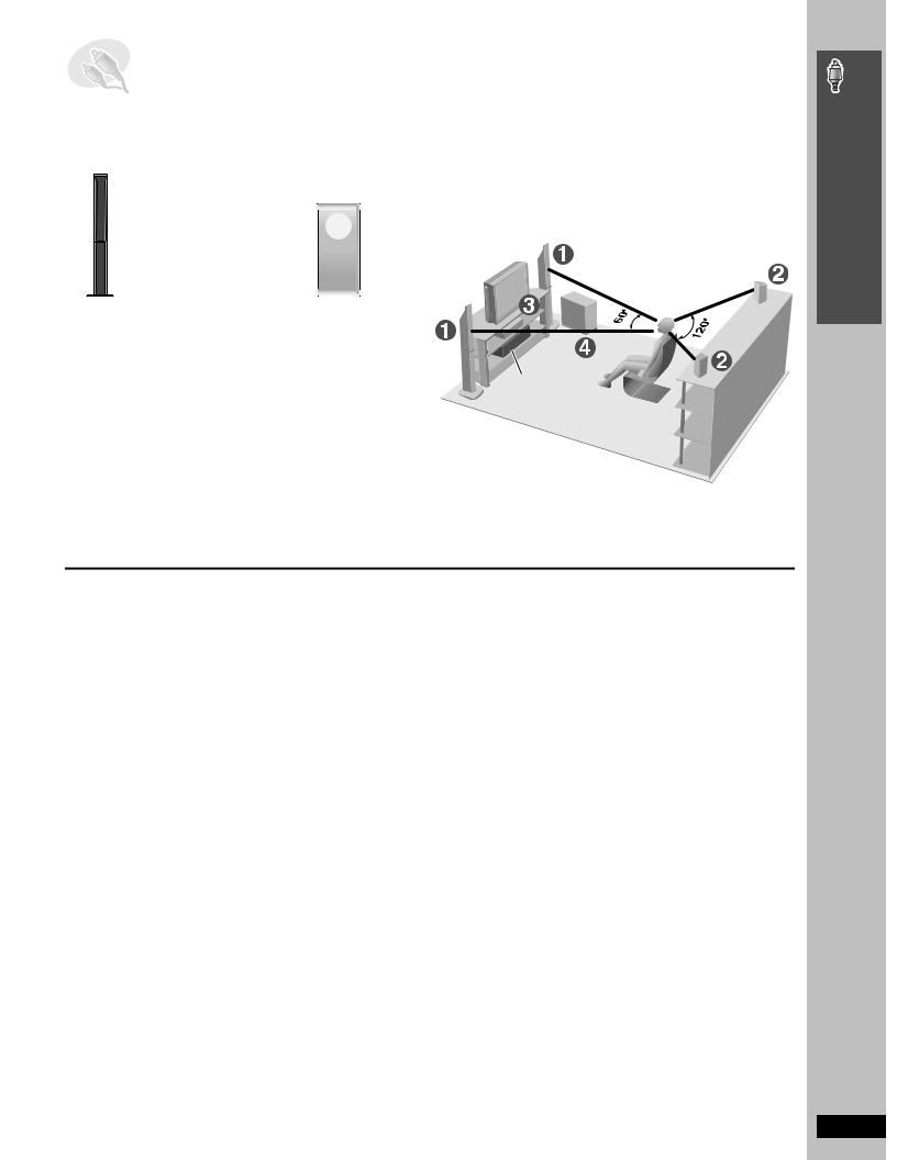
Setup example
Place the front, center, and surround speakers at approximately the same distance from the seating position.
The angles in the diagram are approximate.
e.g. [HT740] [HT743]
Main unit
|
|
|
|
|
|
|
|
|
|
FRONT |
SURROUND CENTER |
SUBWOOFER |
||
(L, R) |
(L, R) |
|
||
≥Use only supplied speakers
Using other speakers can damage the unit, and sound quality will be negatively affected.
≥Set the speakers up on an even surface to prevent them from falling. Take proper precautions to prevent the speakers from falling if you cannot set them up on an even surface.
Main unit
[Note]
≥Keep your speakers at least 10 mm (13/32q) away from the system for proper ventilation.
≥To allow for proper ventilation and to maintain good airflow around the main unit, position it with at least 5 cm (2q) of space on all sides.
≥Do not block the ventilation holes of the main unit.
Notes on speaker use
≥You can damage your speakers and shorten their useful life if you play sound at high levels over extended periods.
≥Reduce the volume in the following cases to avoid damage:
–When playing distorted sound.
–When the speakers are reverberating due to a record player, noise from FM broadcasts, or continuous signals from an oscillator, test disc, or electronic instrument.
–When adjusting the sound quality.
–When turning the unit on or off.
Center speaker
≥Vibration caused by the center speaker can disrupt the picture if it is placed directly on the television. Put the center speaker on a rack or shelf.
≥To prevent the speakers from falling, do not place directly on top of the television.
Subwoofer
Place to the right or left of the television, on the floor or a sturdy shelf so that it will not cause vibration. Leave about 30 cm (1113/16q) from the television.
Caution
≥Do not stand on the base. e.g. [HT740] [HT743] Front speaker Be cautious when children are near.
≥Do not touch the netted area |
|
|
|
|
e.g. [HT740] [HT743] Surround speaker |
||||
of the speakers. |
||||
|
|
|
||
If irregular coloring occurs on your television
The front and center speakers are designed to be used close to a television, but the picture may be affected with some televisions and setup combinations.
If this occurs, turn the television off for about 30 minutes.
The demagnetizing function of the television should correct the problem. If it persists, move the speakers further away from the television.
Caution
≥The main unit and supplied speakers are to be used only as indicated in this setup. Failure to do so may lead to damage to the amplifier and/
or the speakers, and may result in the risk of fire. Consult a qualified service person if damage has occurred or if you experience a sudden change in performance.
≥Do not attempt to attach these speakers to walls using methods other than those described in this manual.
Simple Setup
Positioning the speakers
RQT8582
7
Simple Setup
Speaker connections / Audio and video connections
RQT8582
8
STEP3 Speaker connections
≥Ensure the AC cord is disconnected before you make the speaker connections.
Speaker cables |
2 sheets of speaker cable stickers |
||
≥[HT740] [HT743] 1kshort cable: For center speaker |
≥Attach the speaker-cable stickers to make connection easier. |
||
≥[HT940] 2kshort cables: For center speaker and subwoofer |
FRONT |
SURROUND |
CENTER |
|
1 |
3 |
5 |
≥2klong cables: For surround speakers |
Lch |
Lch |
|
1 |
3 |
5 |
|
|
FRONT SURROUND |
CENTER |
|
|
Lch |
Lch |
|
|
2 |
4 |
6 |
|
Rch |
Rch |
WOOFER |
|
FRONT |
SURROUND |
SUB |
|
FRONT SURROUND |
SUB |
|
|
Rch |
Rch |
WOOFER |
|
2 |
4 |
6 |
Be careful not to cross (short-circuit) or reverse the polarity of the speaker wires as doing so may damage the speakers.
6 SUBWOOFER
 SUB
SUB
WOOFER
6
[HT940] |
|
Insert the |
|
wire fully. |
|
i: White |
Insert the wire fully. |
j: Blue |
i: White |
Push! |
|
Push! |
j: Blue |
The illustration shows SC-HT740 for U.S.A. and Canada.
Speaker cable sticker
CENTER |
CENTER |
|
|
5 |
5 |
|
|
|
|
Insert the |
5 CENTER |
|
|
wire fully. |
|
|
|
i: White |
|
|
|
j: Blue |
|
|
|
Push! |
|
FRONT |
FRONT |
2 FRONT (R) |
|
|
|
||
Rch |
Rch |
|
|
2 |
2 |
|
|
|
|
1 FRONT (L) |
|
FRONT |
|
FRONT |
|
Lch |
|
Lch |
|
1 |
|
1 |
|
|
|
4 SURROUND (R) |
|
SURROUND |
|
SURROUND |
|
Rch |
|
Rch |
|
4 |
|
4 |
|
|
|
3 SURROUND (L) |
|
SURROUND |
SURROUND |
|
|
Lch |
|
Lch |
|
3 |
|
3 |
|
Main unit
DIGITAL
TRANSCEIVER
\For\U.S.A.\and\Canada]only]
Set your surround sound free!
Optional Panasonic wireless accessory (e.g. SH-FX60)
You can enjoy surround speaker sound wirelessly when you use the optional Panasonic wireless accessory (e.g. SH-FX60). For details, please refer to the operating instructions for the optional Panasonic wireless accessory.
STEP4 Audio and video connections
≥Do not connect through the video cassette recorder.
Video cable
Due to copy guard protection, the picture may not be displayed properly.
≥Turn the television off before connecting, and refer to the television’s operating instructions.
Television with an HDMI terminal
HDMI-compatible television |
Back of the main unit |
(not included) |
|
AV IN |
AV OUT |
HDMI cable (not included)
Use the HDMI connection to enjoy higher quality audio and video with a single cable ( page 13, HDMI).
By connecting to an HDMI-compatible high-definition television, you can enjoy high-definition video (720p or 1080i) with 2-channel audio.
≥Set “Video Output” to “On” and “Audio Output” to “On” ( page 24, “HDMI” tab).
≥Set “Video Output Mode” ( page 21, Picture Menu).
[Note]
≥It is recommended that you use Panasonic’s HDMI cable. [Recommended part number: RP-CDHG15 (1.5 m/4.9 ft), RP-CDHG30 (3.0 m/9.8 ft), RP-CDHG50 (5.0 m/16.4 ft), etc.]
≥Non-HDMI-compliant cables cannot be utilized.
[HT940]
Control with HDMI (HDAVI Control)
If your Panasonic television is an HDMI control compatible television, you can operate your television synchronizing with home-theater operations or vice versa [ page 30, [HT940] Operating both the television and the home theater system: Control with HDMI (HDAVI ControlTM)].
≥Make the extra audio connection ( page 9) when you use HDAVI Control function.

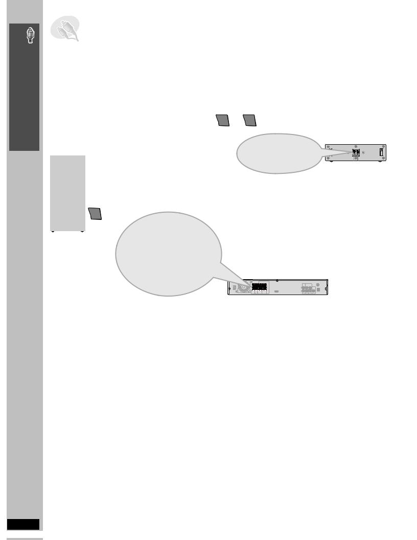
Basic audio connection
Television
RF IN |
(not included) |
Back of the main unit |
|
||
AUDIO |
AUDIO |
AUX COMPONENTVIDEOOUT |
OUT |
IN |
L 

 R
R 


VIDEO OUT VIDEO IN
PB |
Y |
L |
S-VIDEO |
|
OUT |
R |
|
PR |
VIDEO |
|
|
|
OUT |
Audio cable§ (not included)
§[HT940]
Connect the audio cable to the TV AUDIO IN terminal on the main unit and select “TV” as the input source (SELECTOR page 11).
≥This audio connection will enable you to play audio from your television through your home theater system. Refer to “Operating other equipment” ( page 30).
Basic video connection
Television (not included) |
Back of the main unit |
COMPONENTVIDEOOUT |
|
PB |
Y |
Video cable (included) |
S-VIDEO |
VIDEO IN |
OUT |
PR |
VIDEO |
|
|
|
OUT |
Other video connections for improved picture quality
COMPONENT VIDEO OUT
Television |
|
(not included) |
Video cables |
COMPONENT |
(not included) |
VIDEO IN |
|
PB |
|
PR |
|
Y |
|
Back of the |
|
main unit |
|
COMPONENTVIDEOOUT |
|
PB |
Y |
|
S-VIDEO |
|
OUT |
PR |
VIDEO |
|
OUT |
To enjoy progressive video
≥Connect to a progressive output compatible television. 1 Set “Video Output” to “Off” ( page 24, “HDMI” tab). 2 Set “Video Output Mode” to “480p”, and then follow the
instructions on the menu screen ( page 21, Picture Menu).
≥All Panasonic televisions that have 480p input connectors are compatible. Consult the manufacturer if you have another brand of television.
≥Using the COMPONENT VIDEO OUT terminals
The COMPONENT VIDEO OUT terminals provides a purer picture than the S-VIDEO OUT terminal. These terminals can be used for either interlaced or progressive output. Connection using these terminals outputs the color difference signals (PB/PR) and luminance signal (Y) separately in order to achieve high fidelity in reproducing colors.
≥The description of the component video input terminals depends on the television or monitor (e.g. Y/PB/PR, Y/B-Y/R-Y, Y/CB/CR). Connect to terminals of the same color.
≥After making this connection, select “Darker” from the “Black Level Control” in the “Video” tab ( page 24).
S-VIDEO OUT |
|
|
|
Television |
|
Back of the |
|
|
main unit |
||
(not included) |
S-video cable |
COMPONENTVIDEOOUT |
|
|
|||
S-VIDEO |
PB |
Y |
|
(not included) |
|
|
|
IN |
|
S-VIDEO |
|
|
|
|
OUT |
|
|
PR |
VIDEO |
|
|
|
|
|
|
|
OUT |
≥Using the S-VIDEO OUT terminal |
|
|
|
The S-VIDEO OUT terminal achieves a more vivid picture than the
VIDEO OUT terminal by separating the chrominance (C) and luminance
(Y)signals. (Actual results depend on the television.)
∫Cable TV box or video cassette recorder connection
Cable TV box or video cassette recorder
(not included)
|
|
Television |
|
Audio cable§ (not included) |
|
RF IN |
|
§[HT940] |
|
|
(not included) |
|||
To your cable TV |
|
|||
|
Connect the audio cable to |
|||
|
|
|
||
service or television |
|
|
|
|
|
RF IN |
|
the TV AUDIO IN terminal |
|
antenna |
|
|
||
RF OUT |
|
|
on the main unit and select |
|
|
|
|
||
|
|
AUDIO |
AUDIO |
“TV” as the input source |
|
|
OUT |
IN |
(SELECTOR page 11). |
|
RF cable |
|
|
|
|
L |
|
L |
|
|
(not included) |
|
|
|
|
|
|
|
|
|
|
R |
|
R |
|
|
|
Video cable |
|
|
|
|
|
|
|
|
VIDEO OUT VIDEO IN |
(included) |
|
|
|
|
||
Back of the main unit
AUX COMPONENTVIDEOOUT
PB Y
|
S-VIDEO |
|
OUT |
PR |
VIDEO |
|
|
|
OUT |
[HT940]
You can use the AUX terminal for the audio input when you connect another external device (e.g. video cassette recorder). Select “AUX” as the input source (SELECTOR page 11).
Simple Setup
Audio and video connections
RQT8582
9
Simple Setup
Radio and AC cord connections / Preparing the remote control
RQT8582
10
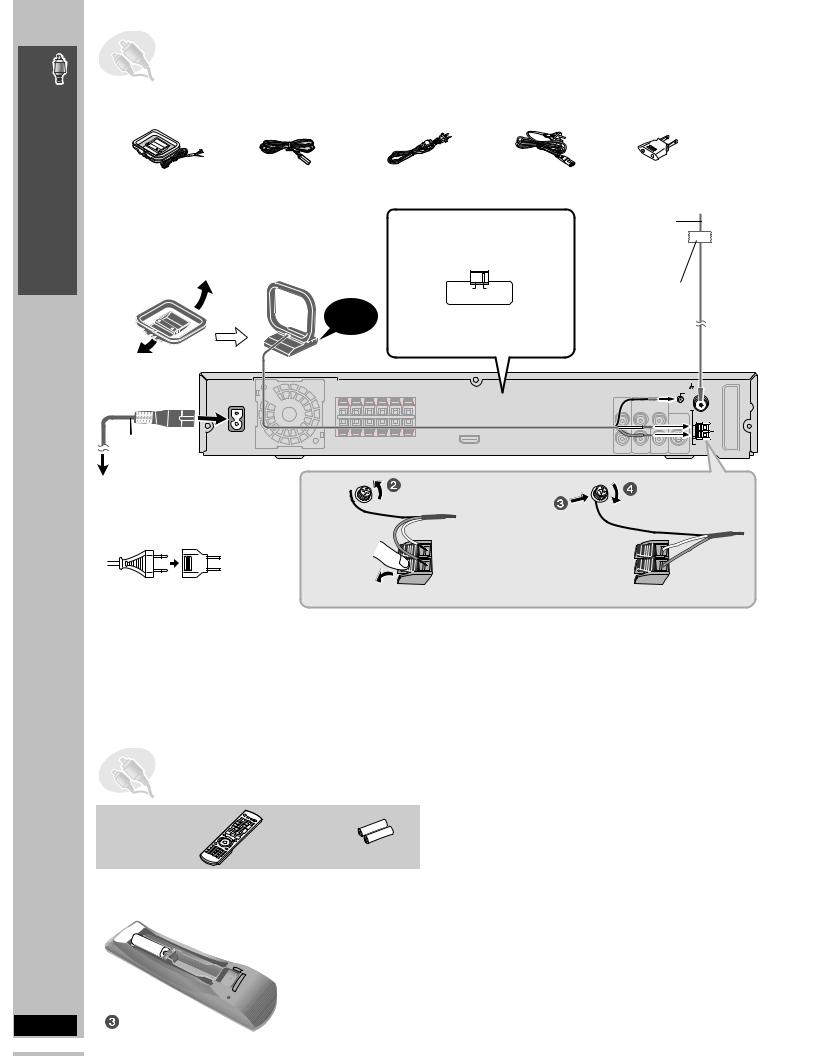
STEP5 Radio and AC cord connections
AM loop antenna |
FM indoor antenna |
AC power supply cord |
|
Power plug adaptor |
|
|
\U.S.A.\and\Canada] |
\Others] |
\Areas\except\U.S.A.\and\Canada] |
|
|
|
|
|
≥Connect the AC power supply cord after all other connections are complete. |
The illustration shows SC-HT740 for U.S.A. and Canada. |
≥Using an outdoor antenna (optional) ( page 27). |
|
AM loop antenna
Stand the antenna up on its base.
Place the antenna where reception is best. Keep loose antenna cable away from other wires and cables.
Click!
Main unit
AC IN 
AC power supply cord
[For\areas\except\U.S.A.[and\Canada]
Before connecting the AC power supply cord
Set the voltage.
110−127V |
220−240V |
VOLT ADJ
Use a flat-head screwdriver to move the voltage selector to the appropriate position for the area in which this system is used.
FM indoor antenna
Affix this end of the antenna where reception is best.
Adhesive tape
LOOP
ANT GND
FM ANT 
 75
75
LOOP
AM |
ANT |
To household AC outlet
[For\areas\except\U.S.A.\and\Canada]
≥If the power plug does not fit your AC outlet
Use the power plug adaptor (included).
If it still does not fit, contact an electrical parts distributor for assistance.
Conserving power
Loosen the terminal screw with a Phillips-head screwdriver.
Black 
Red 
 White
White
 While pushing, insert the wire fully.
Re-tighten the terminal screw.
The main unit consumes a small amount of power, even when it is turned off (For U.S.A. and Canada: approx. 0.4 W or for other areas: approx. 0.9 W). To save power when the unit is not to be used for a long time, unplug it from the household AC outlet.
You will need to reset some memory items after plugging in the unit.
[Note]
The included AC power supply cord is for use with this unit only. Do not use it with other equipment. Also, do not use cords for other equipment with this unit.
STEP6 Preparing the remote control
Remote control |
Batteries |
 Insert so the poles (i and j) match those in the remote control.
 Press in and lift up.
R6/LR6, AA
≥Do not use rechargeable
type batteries.
Replace the cover.
Do not:
≥mix old and new batteries.
≥use different types at the same time.
≥heat or expose to flame.
≥take apart or short circuit.
≥attempt to recharge alkaline or manganese batteries.
≥use batteries if the covering has been peeled off.
Mishandling of batteries can cause electrolyte leakage which can severely damage the remote control.
Remove the batteries if the remote control is not going to be used for a long period of time. Store in a cool, dark place.
∫ Use
Aim at the display ( page 11), avoiding obstacles, at a maximum range of 7 m (23 feet) directly in front of the unit.
STEP7 Performing QUICK SETUP
The QUICK SETUP screen assists you to make necessary settings.
To display the picture from the main unit, turn on your television and change its video input mode (e.g. VIDEO 1, AV 1, etc.).
≥To change your television’s video input mode, refer to its operating instructions.
≥This remote control can perform some basic television operations ( page 30).
1 2 3
|
DVD |
SETUP |
|
||
|
|
|
Turn on the |
Select |
Show the QUICK |
unit. |
“DVD/CD”. |
SETUP screen. |
To change these settings later
Select “QUICK SETUP” in the “Others” tab ( page 24).
Control reference guide
See page references in parentheses.
Turn the unit on/off (11)
Select the source
DVD/CD (11), FM/AM (26), AUX (30)/
FRONT MUSIC P./REAR MUSIC P.§ (31)
[HT940] EXT-IN
TV/AUX (30)/ FRONT MUSIC P./REAR MUSIC P.§ (31)
Select disc’s title numbers etc./Enter numbers (15)
Select the disc or show disc information (16)
Select preset radio stations (26)
Basic operations for play (14, 15)
Select a group of contents to play (15)
Equalizing the sound (14)
Show a disc top menu (18) or program list (19)
4 |
Select |
5 |
6 |
|
RETURN |
|
SETUP |
|
|
ENTER |
|
|
ENTER |
|
|
|
Register |
|
|
Follow the messages and |
Press to finish |
Press to exit. |
|
make the settings. |
QUICK SETUP. |
|
|
|
|
Television operations (30) |
|
TV |
Change the television’s video input mode (30) |
|
TV VIDEO |
|
|
|
|
DVD |
VOLUME |
Adjust the television volume (30) |
FM AM MUSIC P. |
|
|
|
AUX |
Select television channels (30) |
|
|
|
1 |
2 3 |
Adjust the volume of the main unit (15) |
|
CH |
|
4 |
5 |
6 |
[HT940] |
|
7 |
8 |
9 |
Enhance the surround sound (28) |
|
|
0 |
VOLUME |
|
Start up and play a disc automatically/Control both |
DISC |
10 |
|
||
|
|
SLOW SEARCH |
|
the home theater system and the television (30) |
|
|
|
SRD ENH |
SURROUND MUSIC |
SKIP |
|
|
|
Equalizing the sound (14) |
|
|
|
|
|
|
|
|
|
|
|
|
|
|
|
|
|
|
U |
|
|
|
|
|
|
STOP |
|
|
PAUSE |
PLAY |
NETO CH PLA |
|||||||
|
|
|
|
|
|
|
|
O |
Y |
|||||||||
|
|
|
|
|
|
|
|
|
|
|
|
|
|
|
|
|
||
|
|
|
|
|
|
|
|
|
|
|
|
|
||||||
|
|
|
GROUP |
|
|
|
|
|
|
QUICK OSD |
|
Display current playback condition (16) |
||||||
|
|
|
|
|
|
|
|
|
|
|
|
|
|
|
|
|
||
|
|
|
|
|
|
|
|
|
|
|
OUND |
MU |
|
|
|
|
||
|
|
|
|
|
|
|
|
|
|
RR |
SI |
Frame-by-frame/Select or register menu items on the |
||||||
|
|
|
|
|
|
|
|
|
U |
|
|
|
|
|||||
|
|
|
|
|
|
ATO |
S |
|
|
|
|
|
C |
|||||
|
|
|
|
|
|
R |
|
|
|
|
|
|
|
|||||
|
|
|
|
V |
I G |
|
|
|
|
|
|
|
|
|
|
|
television screen (15) |
|
|
CT |
|
|
|
|
|
|
|
|
|
|
U |
||||||
|
|
|
A |
|
|
|
|
|
|
|
|
|
|
|
F |
|
|
|
|
|
|
N |
|
|
U |
|
|
|
|
|
|
|
|
||||
|
E |
|
|
|
|
|
|
|
|
|
N |
|
|
|||||
I |
|
|
|
N |
|
|
|
|
|
|
C |
|
|
|||||
R |
|
|
|
E |
|
|
|
|
|
|
|
|
|
|
||||
D |
|
|
|
|
|
|
|
|
|
T |
|
|
||||||
|
|
|
|
|
|
M |
|
|
ENTER |
I |
Show on-screen menu (20) |
|||||||
|
|
|
|
|
T |
|
|
S |
||||||||||
|
|
|
|
|
|
P |
|
|
|
|
|
|
O |
|
|
|||
|
|
|
|
|
|
O |
|
|
|
|
|
|
N |
|
|
|
||
Show a disc menu (18) or play list (19)
MENU |
|
|
RETURN |
PLAY |
|
|
|
LIST |
|
|
|
CANCEL |
PLAY MODE |
REPEAT |
CD MODE |
SUB WOOFER |
SFC |
PL |
H.BASS |
LEVEL |
|
|
|
SLEEP |
ZOOM |
FL DISPLAY |
C.FOCUS |
SETUP |
TEST |
CH SELECT |
MUTING |
Return to previous screen (15)
CANCEL |
PLAY MODE |
REPEAT |
CD MODE |
(15) |
(17) |
(16) |
(16) |
SUB WOOFER |
SFC |
PL |
H.BASS |
LEVEL |
|||
(29) |
(28) |
(28) |
(29) |
SLEEP |
ZOOM |
FL DISPLAY |
C.FOCUS |
(31) |
(16) |
(15) |
(28) |
SETUP |
TEST |
CH SELECT |
MUTING |
Standby/on switch [POWER Í/I] |
|
|
(23) |
(29) |
(29) |
(31) |
|
|
|
|
|
|
|
||
Press to switch the unit from on to standby mode |
|
< OPEN/CLOSE |
|
||||
or vice versa. In standby mode, the unit is still |
|
|
|
||||
consuming a small amount of power. (14) |
|
|
Open/Close the disc drawer (14) |
||||
MUSIC PORT |
4, 5/ X TUNING W |
|
|
|
|||
|
Skip or slow-search play (14)/ |
|
|
DISC EXCHANGE |
|||
Connect an external device (31) |
|
|
|||||
Select the radio stations (26) |
|
|
Open the disc drawer to |
||||
SURROUND MUSIC |
|
|
|||||
|
|
|
|
exchange the disc in the play |
|||
Equalizing the sound (14) |
Display |
|
|
|
position (14) |
||
|
|
|
|
|
|
DISC SKIP |
|
|
|
|
|
|
|
Skip to the next disc tray (14) |
|
|
|
|
|
|
|
Phones |
|
|
|
|
|
|
|
Connect headphones (31) |
|
5 DISC SELECTOR |
∫/ -TUNE MODE / -FM MODE |
|
Jog LED |
|
|||
|
VOLUME |
|
|
||||
Select the disc tray (14) Stop playing (14)/Select the tuning mode (26) |
|
|
|||||
Turn up/down the volume (14) |
|||||||
|
Adjust the FM reception condition (26) |
|
|||||
|
1/ MEMORY |
|
SELECTOR (26) |
|
|
||
|
|
DVD/CD #FM#AM#([HT940] TV)#AUX # |
|||||
|
Play discs (14)/Memorize the receiving |
||||||
|
radio stations |
(26) |
FRONT MUSIC P. |
|
§ |
||
|
# REAR MUSIC P.# |
||||||
§Refer to page 31, Using the Music Port. |
Return to DVD/CD |
|
Simple Setup
Performing QUICK SETUP / Control reference guide
RQT8582
11
Discs that can be played/ Disc caution/ Maintenance
Discs that can be played
Operations in these instructions are described mainly with formats. Icons such as [DVD-V] show the formats.
DVD-Video [DVD-V]
—
DVD-Audio [DVD-A] [DVD-V]
≥[DVD-V] Some DVD-Audio discs contain DVD-Video content. To play DVD-Video content, select “Play as DVD-Video” in Other Menu ( page 22).
Video CD [VCD]
≥Including SVCD (Conforming to IEC62107)
DVD-RAM [DVD-VR] [MP3] [JPEG]
≥[DVD-VR] Recorded with devices using Version 1.1 of the Video Recording Format (a unified video recording standard), such as DVD video recorders, DVD video cameras, personal computers, etc.
≥[JPEG] Recorded with Panasonic SD multi cameras or DVD video recorders using the DCF (Design rule for Camera File system) Standard Version 1.0.
DVD-R (DVD-Video)§1/DVD-RW (DVD-Video) [DVD-V]
≥Discs recorded and finalized§2 on DVD video recorders or DVD video cameras.
DVD-R (VR)§1/DVD-RW (VR) [DVD-VR]
≥Discs recorded and finalized§2 on DVD video recorders or DVD video cameras using Version 1.1 (or 1.2 for DVD-R DL only) of the Video Recording Format (a unified video recording standard).
DVD-R/DVD-RW [MP3] [JPEG]
≥Finalize§2 the disc after recording.
iR (Video)§1/iRW (Video) [DVD-V]
—≥Discs recorded and finalized§2 on DVD video recorders or DVD video cameras.
CD [CD] [WMA] [MP3] [JPEG] [VCD]
≥This unit can play CD-R/RW recorded with the above formats. Close the sessions or finalize§2 the disc after recording. ≥[CD] This unit is compatible with HDCD, but does not support the Peak Extend function (a function which expands the
dynamic range of high-level signals).
HDCD-encoded CDs sound better because they are encoded with 20 bits, as compared with 16 bits for all other CDs. ≥[WMA] [MP3] [JPEG] This unit also plays HighMAT discs.
≥[WMA] This unit does not support Multiple Bit Rate (MBR: a file that contains the same content encoded at several different bit rates).
§1 Includes single-sided, dual-layer discs.
§2 A process that allows play on compatible equipment.
≥It may not be possible to play all the above-mentioned discs in some cases due to the type of disc or condition of the recording.
∫ Discs that cannot be played
Note about using a DualDisc
DVD-RW version 1.0, DVD-ROM, CD-ROM, CDV, CD-G, SACD,
DivX Video Discs and Photo CD, DVD-RAM that cannot be removed
≥The digital audio content side of a DualDisc does not meet the
from their cartridge, 2.6-GB and 5.2-GB DVD-RAM, and “Chaoji
technical specifications of the Compact Disc Digital Audio
VCD” available on the market including CVD, DVCD and SVCD that
(CD-DA) format so playback may not be possible.
do not conform to IEC62107.
≥Do not use a DualDisc in this unit as it may not be possible to insert it correctly and it may get scratched or scraped.
Disc caution |
|
Maintenance |
|
|
|
∫ To clean discs
Wipe with a damp cloth and then wipe dry.
∫ Disc handling precautions
≥Do not attach labels or stickers to discs. This may cause disc warping, rendering it unusable.
≥Do not write on the label side with a ball-point pen or other writing instrument.
≥Do not use record cleaning sprays, benzine, thinner, liquids which prevent static electricity, or any other solvent.
|
|
≥Do not use scratch-proof protectors or covers. |
|
RQT8582 |
≥Do not use the following discs: |
|
– Discs with exposed adhesive from removed stickers or labels |
|
|
|
|
|
|
(rented discs, etc.). |
|
|
– Discs that are badly warped or cracked. |
12 |
|
– Irregularly shaped discs, such as heart shapes. |
|
|
|
Clean this unit with a soft, dry cloth.
≥Never use alcohol, paint thinner or benzine to clean this unit.
≥Before using chemically treated cloth, carefully read the instructions that came with the cloth.
Do not use commercially available lens cleaners as they may cause malfunction. Cleaning of the lens is generally not necessary although this depends on the operating environment.
Before moving the unit, ensure the disc trays are empty. Failure to do so will risk severely damaging the discs and the unit.
 Loading...