


NV-FJ616
http://cxema.ru
ORDER NO. VRD0102005C2
Video Cassette Recorder
NV-FJ616EG
NV-FJ616EGY
NV-FJ616EC
NV-FJ616ECM
NV-FJ616ECN
NV-FJ616ECY
Z-MECHANISM
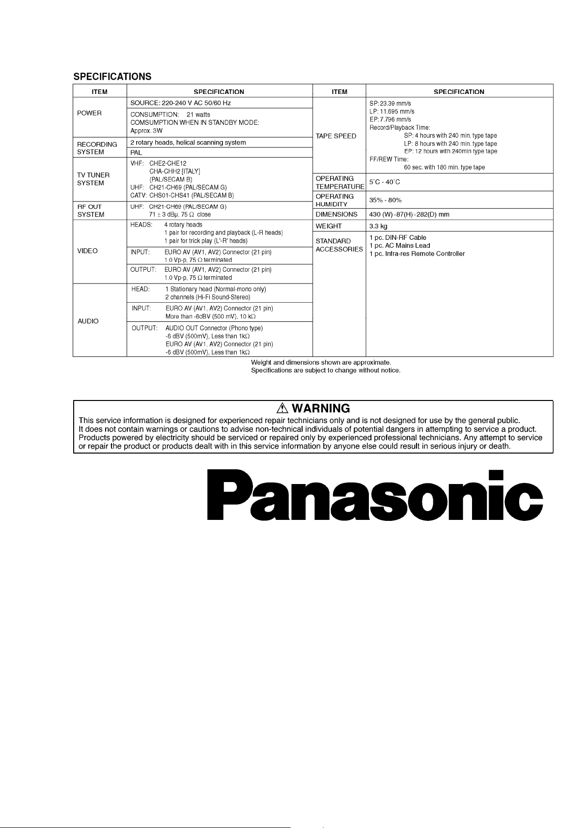
SPECIFICATIONS
http://cxema.ru
1
1. INTRODUCTION
This service manual contains technical information which will allow service
personnel to understand and service this model.
If the circuit is changed or modified, this information will be followed by
supplementary service manual to be filed with original service manual.
Note:
1. Adjustment procedures, Disassembly Procedures and Assembly Procedures for
Mechanism Chassis are separate volume from this service manual.
Please refer to the service manual for Z-Mechanism Chassis. (Order No.
VRD9802005C2)
2. The Model No. is indicated on the Schematic Diagram and Circuit Board Diagrams

http://cxema.ru
as follows.
Model No. Indication Mark
NV-FJ616EG (A)
NV-FJ616EGY (B)
————— (C)
————— (D)
NV-FJ616EC/ECM/ECN (E)
NV-FJ616ECY (F)
2. GENERAL DESCRIPTIONS
2.1. SERVICE CAUTION
2.1.1. REPLACING IC7702/EEPROM
When the EEPROM: IC7702 is replaced, applicable model code, option code and
electrical adjustment data will not be available.
Therefore, enter and/or adjust the necessary data after replacing IC7702 by referring
following procedure.
STEP1.REPLACE THE IC7702
1. Remove the C.B.A. with Mechanism unit by referring the Disassembly procedure.
2. Disconnect the AC plug and replace the IC7702.
STEP2.INPUT THE MODEL & OPTION CODE
1. Set up the applicable model code and option code by ordering the following table.
http://cxema.ru
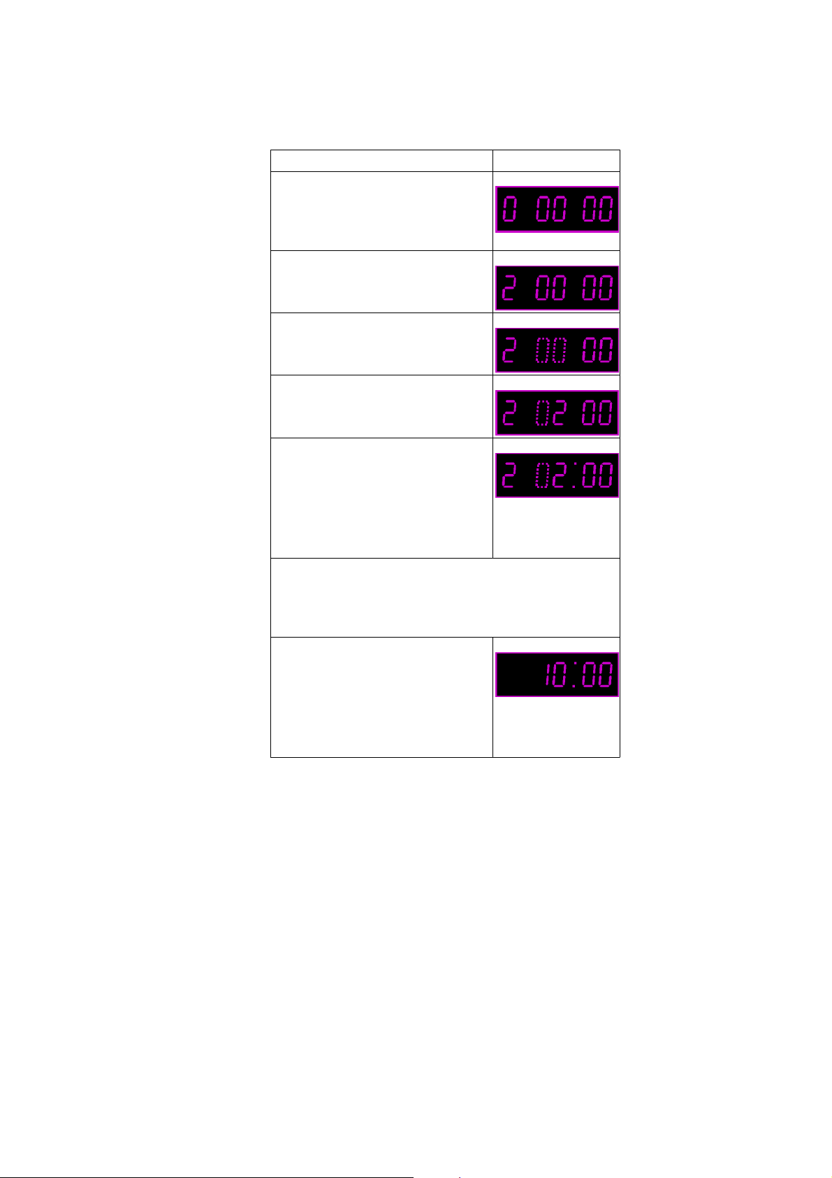
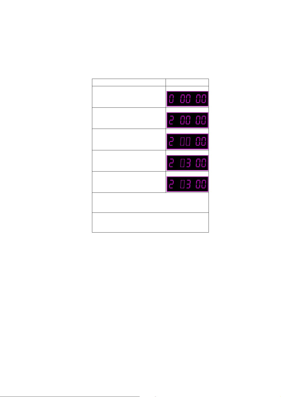
PROCEDURE F.I.P. DISPLAY
Turn on the Service Mode
1.Press the FF key and the
EJECT key simultaneously for
more than 3 seconds.
Activate the Service Mode 2
2.While keep placing FF key,
press the EJECT key in twice.
Activate the Entering Mode.
3.Press the EJECT key for more
than 3 seconds.
Set the Mode 2.
4.Press the CH UP key in twice.
Display the Setting Code.
5.Press the POWER Button to
turn the power on.
(Colon starts
flashing)
Enter the Model and Option Code.
6.Set the applicable Model and Option code by
using REW, PLAY, STOP and FF keys on the
Remote Controller. (See Fig.S1 & S2)
Exit from Service Mode.
7.Press the POWER Button to
turn the power off.
8. Press FF and EJECT keys
simultaneously in 6 times.
(Normal
Indication)
Fig.S1 Service Secreen (sample)
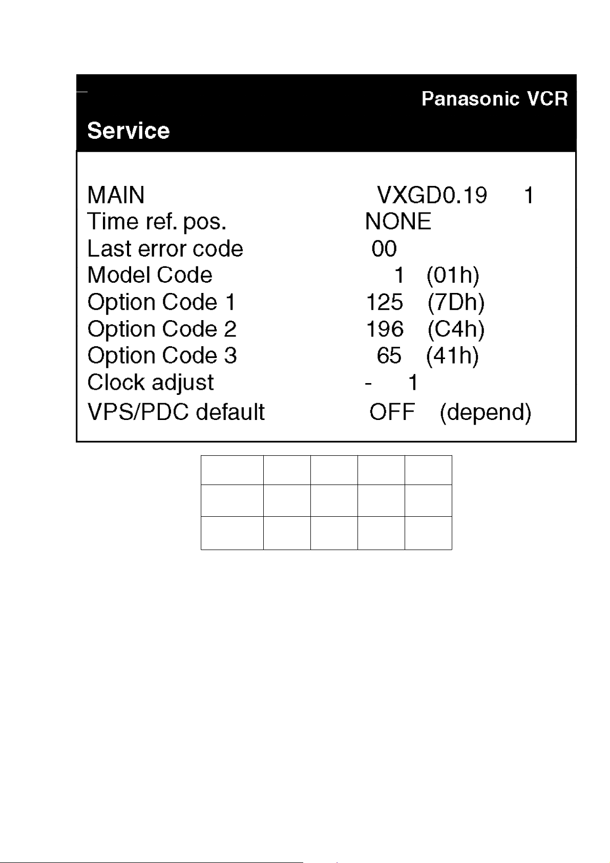
http://cxema.ru
Model No. Model
Code
Option
Code 1
Option
Code 2
Option
Code 3
NV-FJ616EG/
EGY
81
(51h)
8
(08h)
212
(D4h)
6
(06h)
NV-FJ616EC/
ECM/ECN/ECY
82
(52h)
8
(08h)
212
(D4h)
6
(06h)
Fig. S2 Model Code & Option Code
NOTE:
Since all electrical adjustments data is still not available, perform the Electrical
Adjustment continuously.
2.1.2. CYLINDER UNIT REPLACEMENT
1. CYLINDER UNIT REPLACEMENT
A. Remove the mechanism unit from MAIN C.B.A./Chassis by referring “SECTION
2. Disassembly Procedure”.
B. Remove the 3 screws (A) of the CYLINDER UNIT with a screw driver.
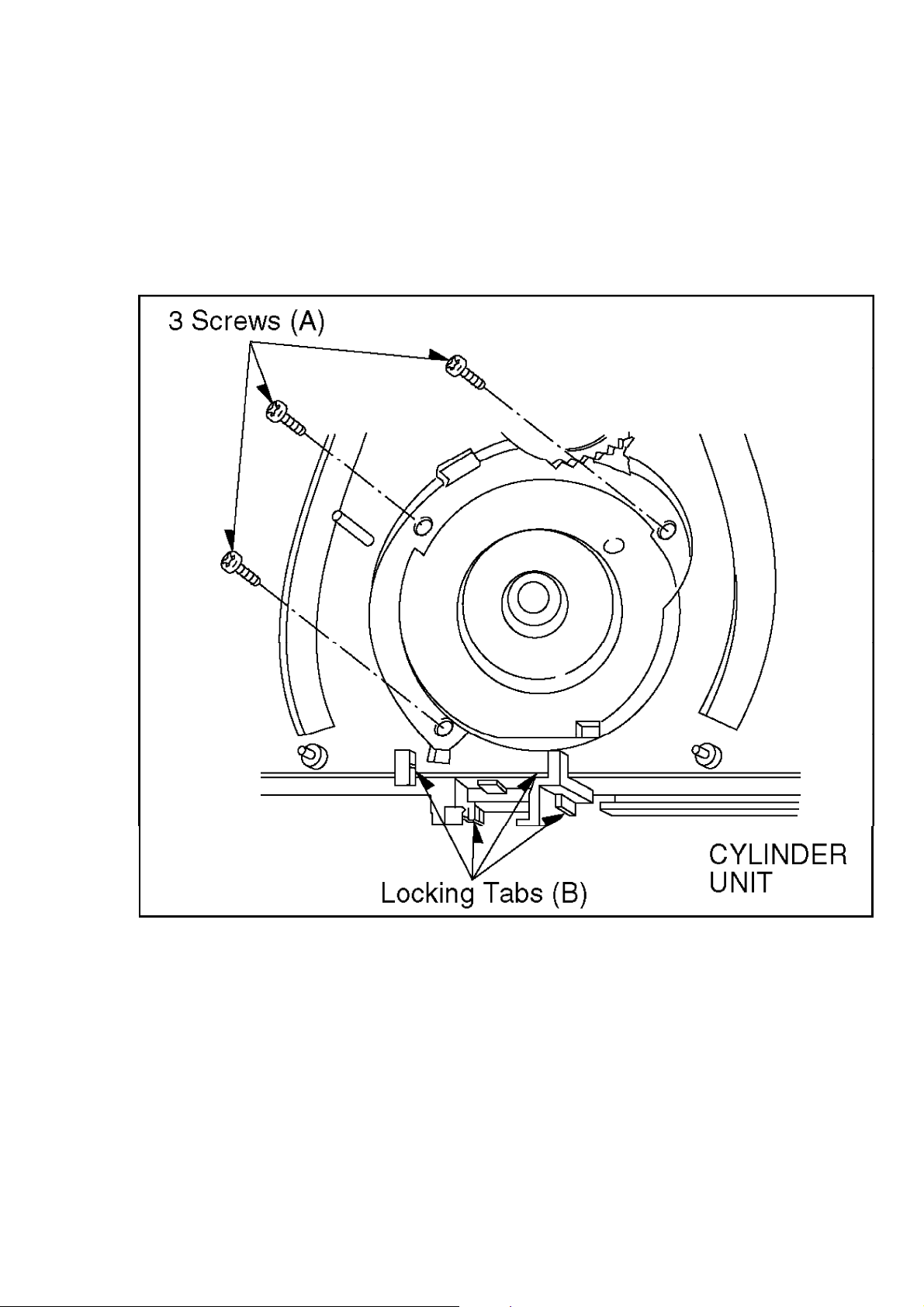
http://cxema.ru
C. Unlock the 4 locking tabs (B) and disconnect the Cylinder fiexible card from the
FPC Holder.
D. Remove the CYLINDER UNIT.
CAUTION:
Handle the Cylinder fiexible card with care. When it damaged, you should replace
whole Cylinder unit.
Fig. S3
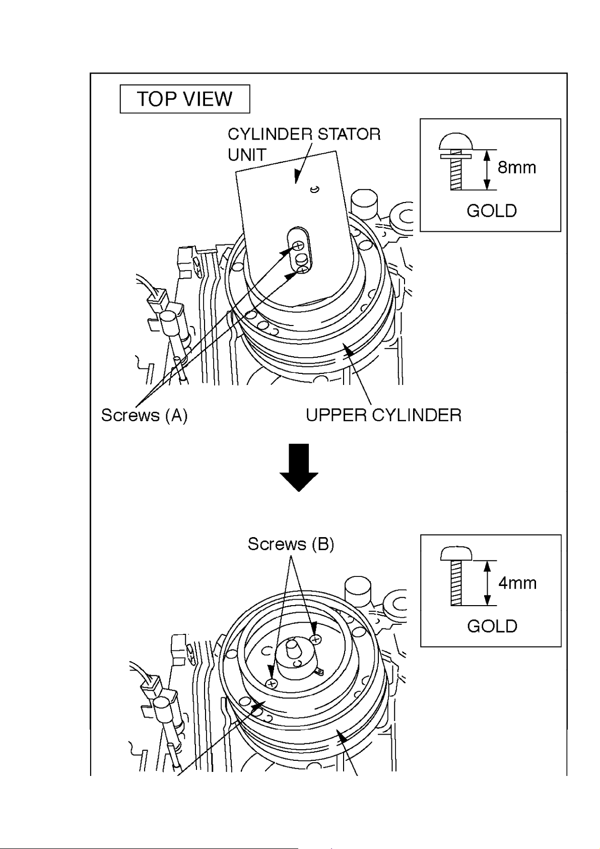
2. UPPER CYLINDER DISASSEMBLY
A. Remove 2 screws (A).
B. Remove the Cylinder Stator Unit.
C. Remove 2 screws (B).
D. Remove the Cylinder Rotor Unit.
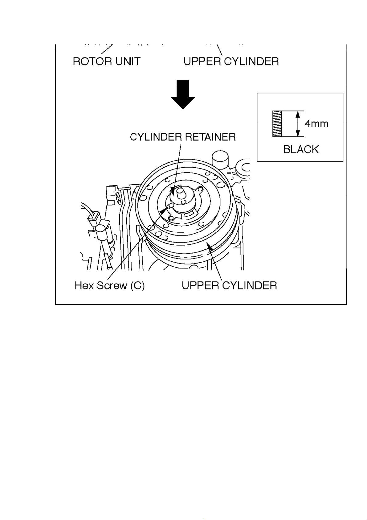
E. Loose Hex screw (C) (1.5 mm) and remove the CYLINDER RETAINER.
F. Remove the Upper Cylinder.
Fig. S4
http://cxema.ru
http://cxema.ru
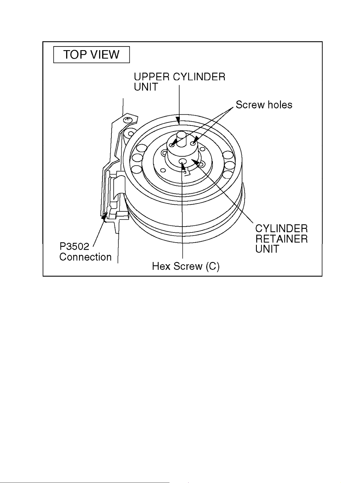
3. UPPER CYLINDER ASSEMBLY
When reassembling, perform the steps in the reverse order.
Notes:
1. Install the Cylinder Retainer so that the 2 holes on top of the Cylinder Retainer are
at right angles with the P3502 Connection.
2. Tighten the Hex screw (C) (1.5 mm) while pressing down on top of the Cylinder
Retainer.
Fig. S5
http://cxema.ru
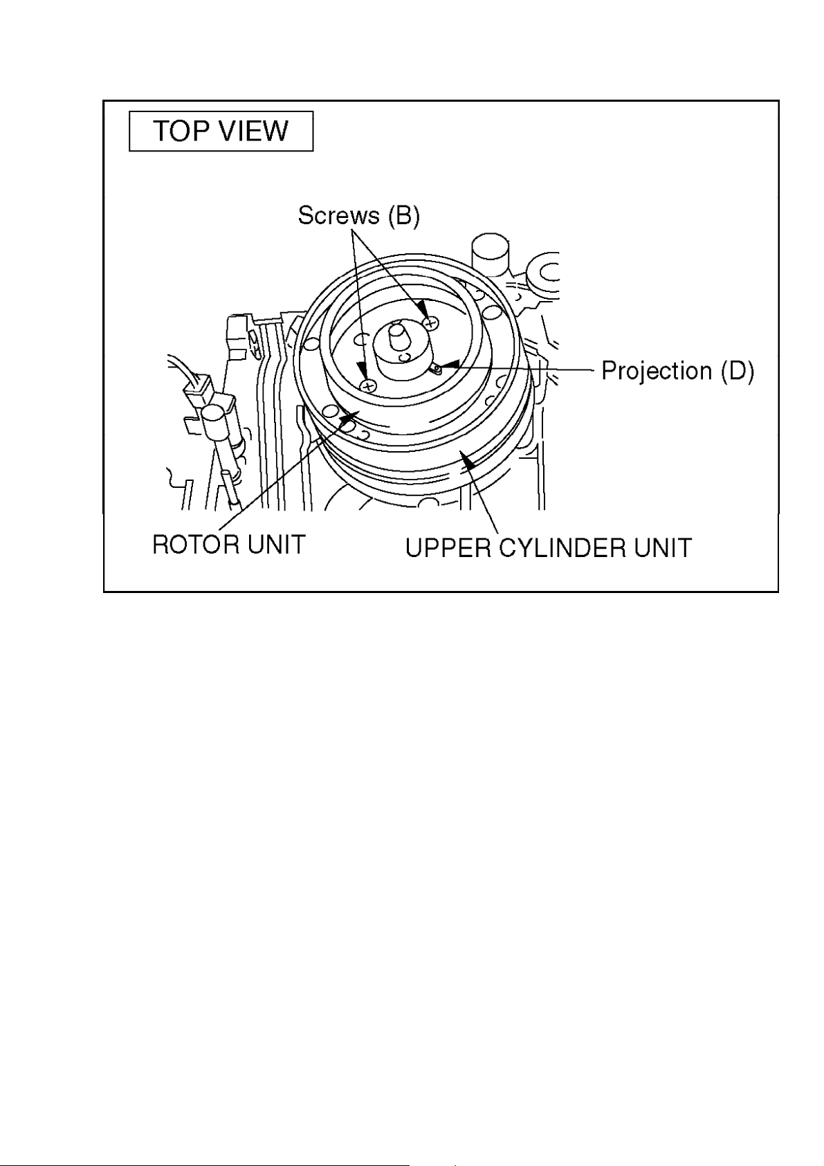
3. Install the Cylinder Rotor Unit so that the inner hole of the Cylinder Rotor Unit fits
to the small projection (D) on top of the Upper Cylinder.
4. Tighten 2 screws (B).
Fig. S6
http://cxema.ru
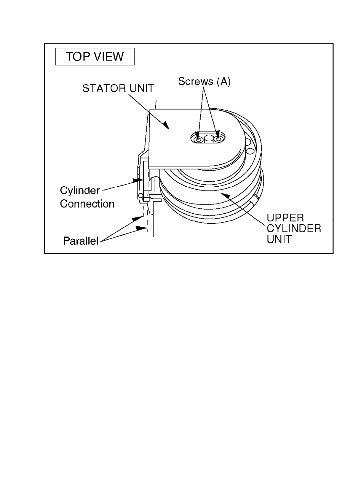
5. install the Cylinder Stator Unit.
6. Tighten 2 screws (A).
Fig. S7
http://cxema.ru
7. Confirm the PG SHIFTER ADJUSTMENT with the alignment tape (PAL:
VFJ8125H3F) and adjust it if necessary.
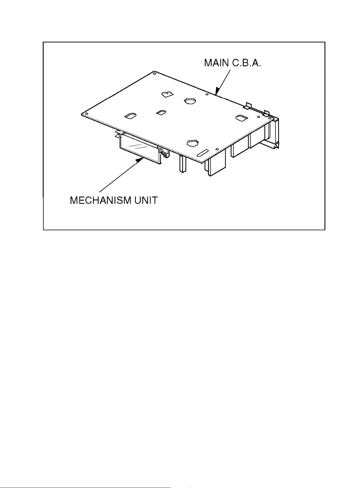
2.1.3. CHECKING OF MAIN C.B.A.
When servicing the MAIN C.B.A., take out the MAIN C.B.A. and mechanism from the
frame and turn over.
Fig. S8
http://cxema.ru
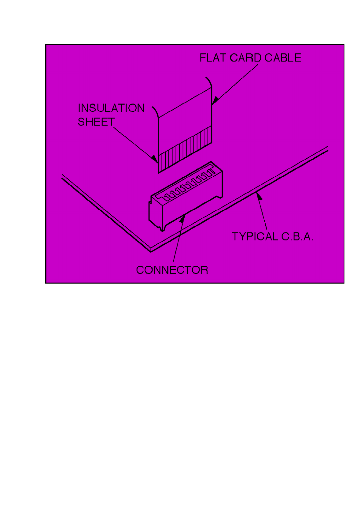
2.1.4. FLAT CARD CABLE INSTALLATION
When installing the Flat Card Cable on the connector, install the Flat Card Cable with
the cable contacts facing the connector contacts.
Fig. S9
http://cxema.ru
2.2. REMOVAL OF CASSETTE TAPE
There are 2 ways to remove a cassette tape.
1. Service Information Display Operation
A. Press the FF and EJECT keys simultaneosly for 3 seconds and set the Service
Mode 7.
B. Press STOP key in order to rotate the Loading Motor for unloading operation.
(Pay an attention of tape slack)
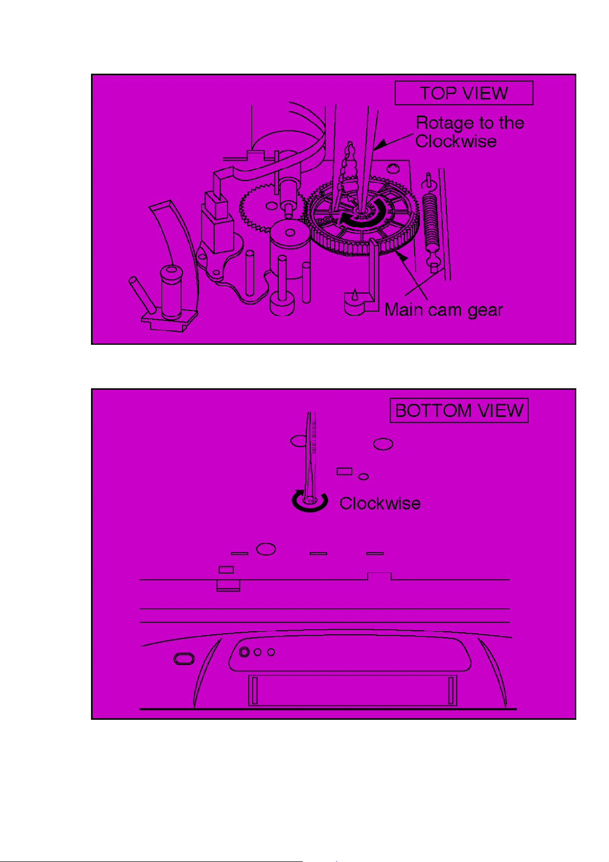
2. Manual Operation
A. Disconnect the AC Mains Lead and remove the Top Panel.
B. Rotate the Main Cam Gear clockwise until the Loading Posts move to fully
unloaded position as shown in
Fig. S10 . (Tape is remaining)
Fig. S10
http://cxema.ru
C. Rotate the Capstan Motor clockwise from the bottom side to take up the tape.
Fig. S11
D. Rotate the Main Cam Gear clockwise until the cassette tape is ejected.
2.3. INTRODUCTION OF VIDEO HEAD CLEANING CASSETTE

http://cxema.ru
(POLISHING TYPE)
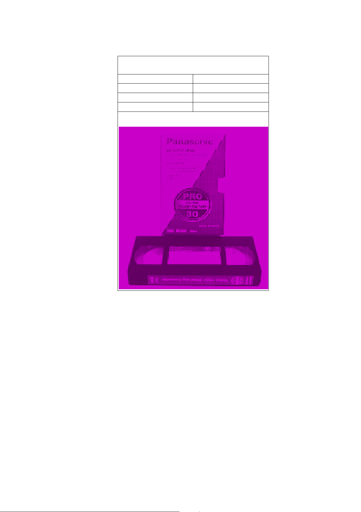
1. We are pleased to introduce Panasonic Video Head Cleaning Cassette, VFK0923FT
[for service purposes] and VFK0923FSE [ for end users] for all VHS/SVHS VCP and
VCR.
2. These cleaning cassettes are exclusive removing the hard and sticky clogging on
video heads.
3. These improve the efficiency of video head cleaning service and shortening
cleaning time for end users.
VFK0923FT
(For Service usage)
Type of Cassette Full VHS Cassette
Cleaning Time 10 Seconds/Time
Tape Length 20 m
Usability in a Path 180 Times
http://cxema.ru
VFK0823FSE
(For end users)
Type of Cassette Full VHS Cassette
Cleaning Time 10 Seconds/Time
Tape Length 3.34 m
Usability in a Path 30 Times
Note:
The tape material itself is the same in both types.
2.4. SELF-DIAGNOSIS RESULT DISPLAY
The "SELF-DIAGNOSIS RESULT DISPLAY & MEMORY function is built in this VTR.
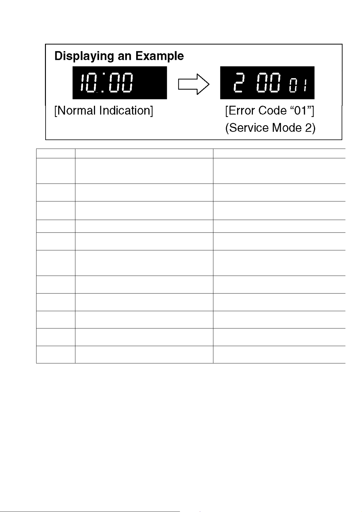
It means that when the VCR detects undesirable condition, it can be displayed a
“Error code (Two numbers from the left)” with Service Mode 2.
Since the "Error code" is stored in the EEPROM, it can be displayed although after
disconnected the AC leads. It can be displayed with Service Mode 2.
(If a second error had been detected, only the most recent error is displayed. )
For more details, refer to the Service Manual for Z-Mechanism Chassis Order number
VRD9612M129.
http://cxema.ru
INDICATION CAUSE REMEDY/CHECK
01 After cylinder lock is detected, the cylinder
does not start rotating again even after tape
unloading.
Check the cylinder motor drive circuit.
02 Cassette tape is not wound up during the tape
unloading except EJECT mode.
Check the capstan motor drive circuit.
03 Mechanism locks during mode transition
except EJECT mode.
1. Check the loading motor drive circuit.
2. Check the mechanism phase alignment.
3. Check the mode switch.
04 Mechanism locks during tape unloading.
1. Check the loading motor drive circuit.
2. Check the mechanism phase alignment.
06 Mechanism locks after tape unloading in
EJECT mode.
1. Check the loading motor drive circuit.
2. Check the mechanism phase alignment for cassette holder un
i
07 During recording mode, recording signal is
less than the normal condition.
Protection of the over-current flowing in
transistor which produces the power supply
for recording mode.
08 Recording circuit works except recording
mode.
Check the recording circuit.
16 Cylinder lock detection. Check the cylinder unit and the cylinder moto
drive circuit.
17 Supply reel mechanism lock detection Check the supply reel mechanism and the
supply reel circuit.
18 Take-up reel mechanism lock detection Check the Take-up reel mechanism and the
Take-up reel circuit.
2* PG shifter automatic adjustment error. Check the servo/system control circuit and
the cylinder unit.
Fig. T1 Self-Test indication Display
3. ADJUSTMENT PROCEDURES
3.1. DISASSEMBLY METHOD
3.1.1. DISASSEMBLY FLOW CHART

http://cxema.ru
This flow chart indicates disassembly steps of the cabinet parts and the circuit
boards in order to find the necessary items for servicing.
When reassembling, perform the steps in the reverse order.
Fig. D1
3.1.2. DETAIL OF DISASSEMBLY METHOD

http://cxema.ru
1. REMOVAL OF THE TOP PANEL
Remove 4 Screws (A)
Fig.D2
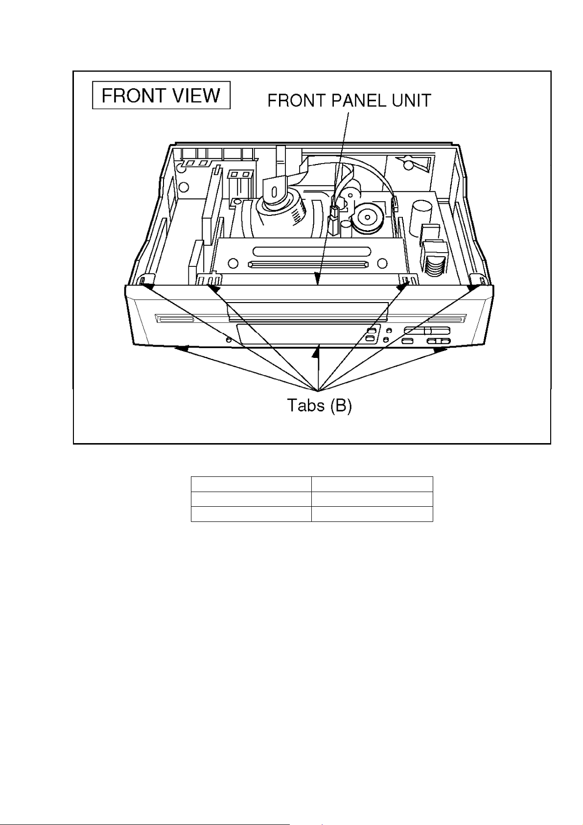
2. REMOVAL OF THE FRONT PANEL UNIT
Unlock 7 Tabs (B)
Fig. D3
http://cxema.ru
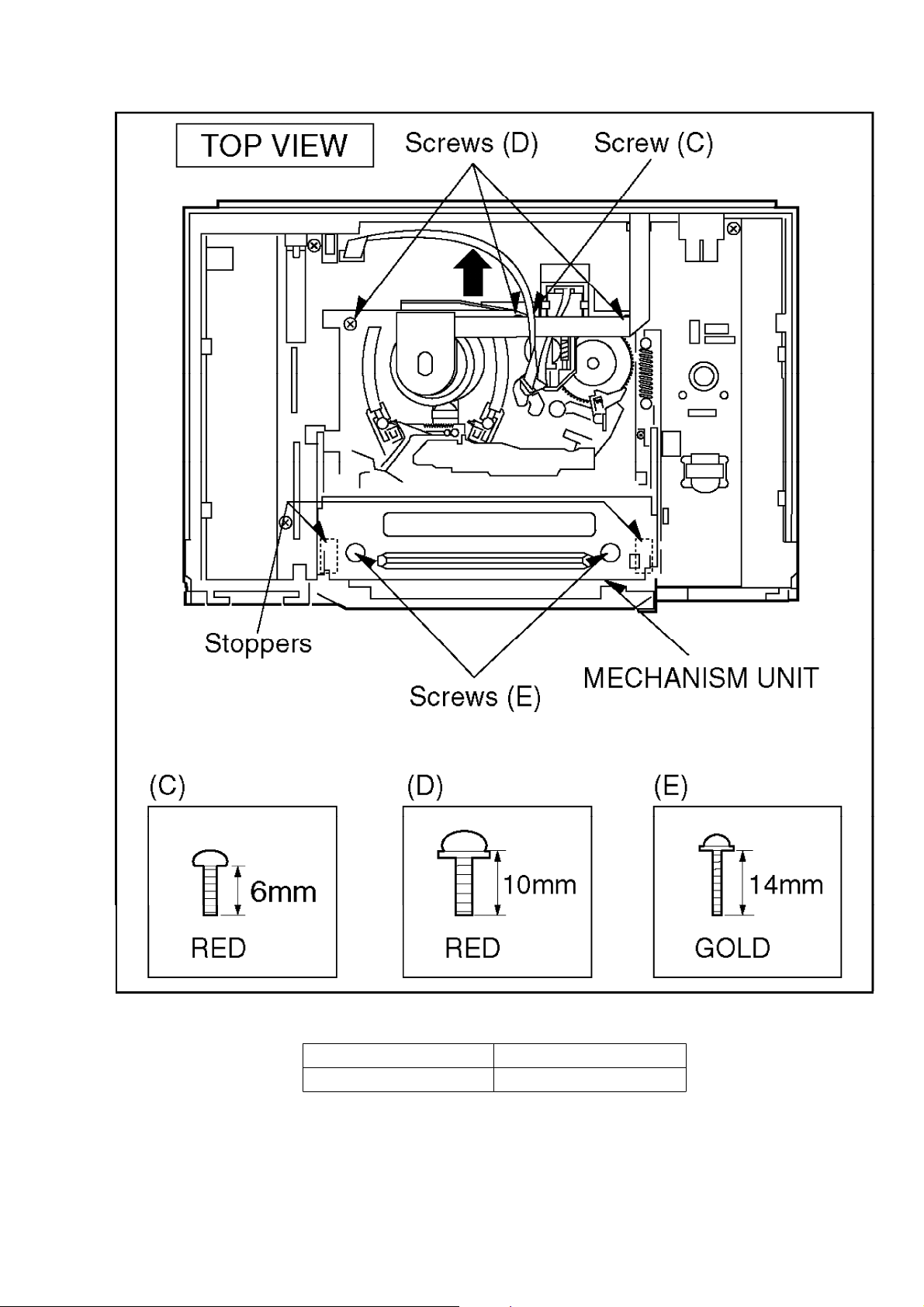
3. REMOVAL OF THE MECHANISM UNIT
Remove Screw (C)
Remove 3 Screws (D)
Remove 2 screw (E)
Note:
1. Keep pressing 2 stoppers on Cassette Holder Plate and Press Cassette Holder
Plate to the rear.
2. Remove the Mechanism Unit after bend the Cylinder Shield in the direction of the
arrow.
Fig. D4
http://cxema.ru
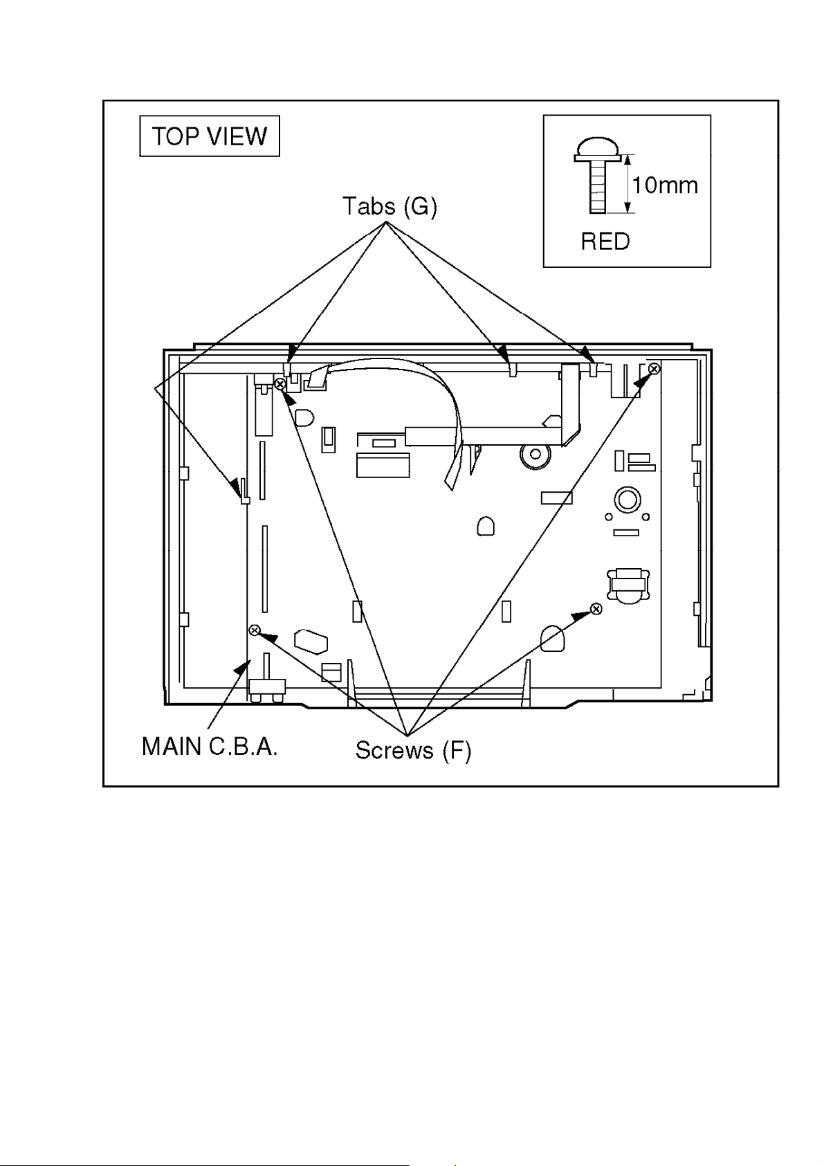
4. REMOVAL OF THE MAIN C.B.A.
Remove 4 screws (F)
Unlock 4 Tabs (G)
Fig. D5
http://cxema.ru
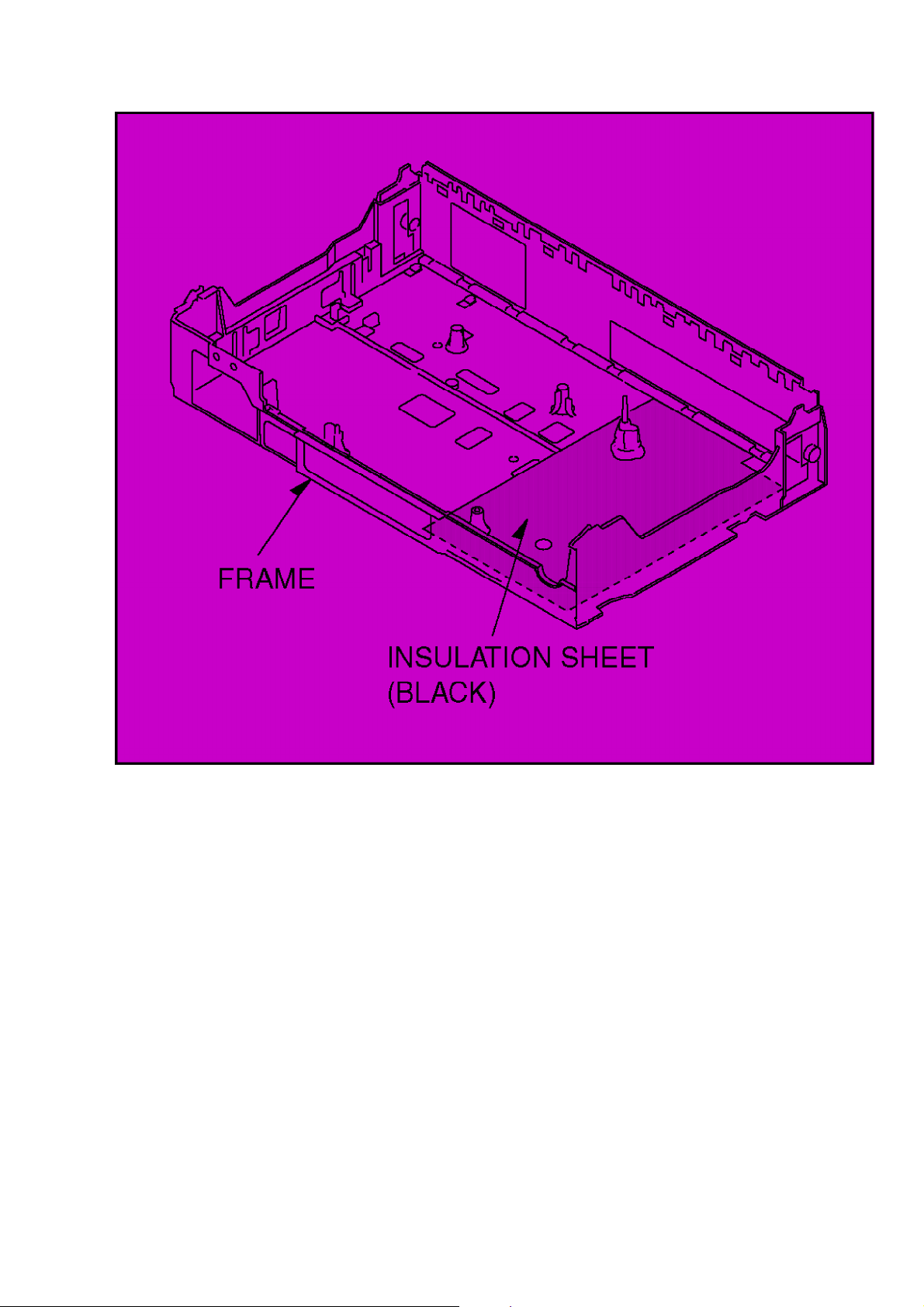
NOTE:
Before mounting the MAIN C.B.A. onto the frame, be sure to confirm that the
insulation sheet is mounted on the frame as shown in Fig. D6.
Fig. D6
http://cxema.ru
5. SERVICING POSITION
Fig. D7

http://cxema.ru
3.2. MECHANICAL ADJUSTMENT PROCEDURES
Refer to the Service Manual for Z-Mechanism Chassis.
(Order No. VRD9802005C2)
3.3. ELECTRICAL ADJUSTMENT PROCEDURES
3.3.1. TEST EQUIPMENT
The following equipments are required for Electrical Adjustments.
1. Dual-Trace Oscilloscope
- Voltage Range: 0.005-5V/div
- Frequency Range: DC-35MHz
- Probes: 10:1 / 1:1
2. Frequency Counter
- Frequency Range: 0-10MHz
- Probes: 1:1
3. Universal Counter
4. Digital Volt Meter (D.V.M.)
5. Video Sweep Generator

http://cxema.ru
6. Sinewave Generator
7. Video Pattern Generator
8. Monitor TV
9. DC Power Supply
10. VHS Blank Tape
11. VHS Alignment Tape
- Parts No.: VFJ8125H3F(PAL)
3.3.2. VCR SETTING
When no indication in the procedure, set each selector as follows.
1. TAPE SPEED: SP
2. CHANNEL: AV1/AV2
(Set to signal input terminal number)
3.3.3. ADJUSTMENTS
ITEM TP ADJ. MODE INPUT TAPE M. EQ. SPEC. REMARKS
PG
SHIFTER
ADJUSTMENT
--- ---
PLAYBACK
---
ALIGNMENT
TAPE
(PAL)
--- --- Refer to procedure of
PG SHIFTER
ADJUSTMENT as show
n
in Fig.E3.
AI
FUNCTION
ADJUSTMENT
--- ---
PLAYBACK
(SELF-REC)
PAL
COLOUR
BAR
BLANK
TAPE
--- --- Refer to the procedure
of AI FUNCTION
ADJUSTMENT as show
n
in Fig.E4.
VIDEO
FREQUENCY
RESPONSE
ADJUSTMENT
VIDEO
OUT
--- SP/LP/EP
PLAYBACK
(SELF-REC)
VIDEO
SWEEP
(See
Fig.E1)
BLANK
TAPE
OSCILLO
SCOPE/
VIDEO
SWEEP
GENERATOR
SP: 0+-1
(dB)
(90~110%)
LP: 0+-1
(dB)
(90~110%)
EP: 0+-3
(dB)
(70~140%)
(See Fig.
E2)
Refer to the procedure
of VIDEO FREQUENCY
RESPONSE
ADJUSTMENT as show
n
in Fig. E5.
http://cxema.ru
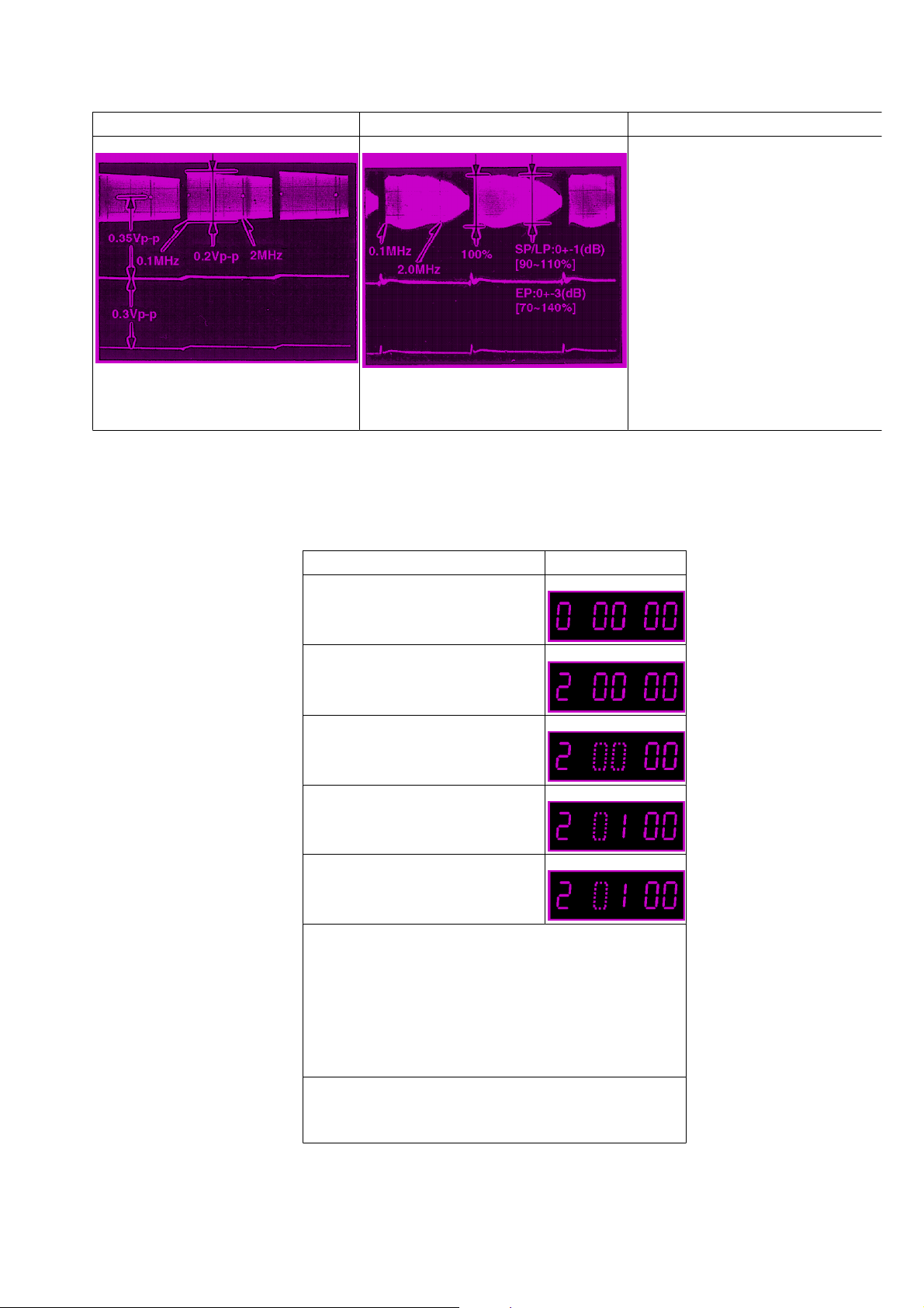
Fig.E1 Fig.E2
CONDITION: BURST SIGNAL OFF /
75 ohm TERMINATED
3.3.4. PG SHIFTER ADJUSTMENT
(AUTOMATIC)
PROCEDURES FIP DISPLAY
Press the FF and EJECT Keys
simultaneously for 3 seconds.
Press the FF and EJECT Keys
simultaneously twice.
Press the EJECT key for 3
seconds.
Press the CH UP key once.
Insert the Alignment cassette
tape. (PAL:VFJ8125H3F)
When the sequence of the automatical adjustment
has been terminated, the following action has
been made.
*SUCCEED: The cassette tape is ejected.
*ERROR : The "F2"is displayed on the FIP.
(Check the Servo/Syscon circuit and
Cylinder unit.)
Release the Service mode by pressing the EJECT
and FF keys simultaneously in 6 times until the FIP
becomes normal indication.
http://cxema.ru
Fig. E3
3.3.5. AI FUNCTION ADJUSTMENT (AUTOMATIC)
PROCEDURES FIP DISPLAY
Press the FF and EJECT Keys
simultaneously for 3 seconds.
Press the FF and EJECT Keys
simultaneously twice.
Press the EJECT key for 3
seconds.
Press the CH UP key in 3 times.
Insert the blank cassette tape.
(The adjustment is
automatically started.)
When the sequence of the automatical adjustment
has been terminated successfully, the VCR goes
to STOP mode.
Release the Service mode by pressing the EJECT
and FF keys simultaneously in 6 times until the FIP
becomes normal indication.
Fig. E4
3.3.6. VIDEO FREQUENCY RESPONSE ADJUSTMENT
http://cxema.ru
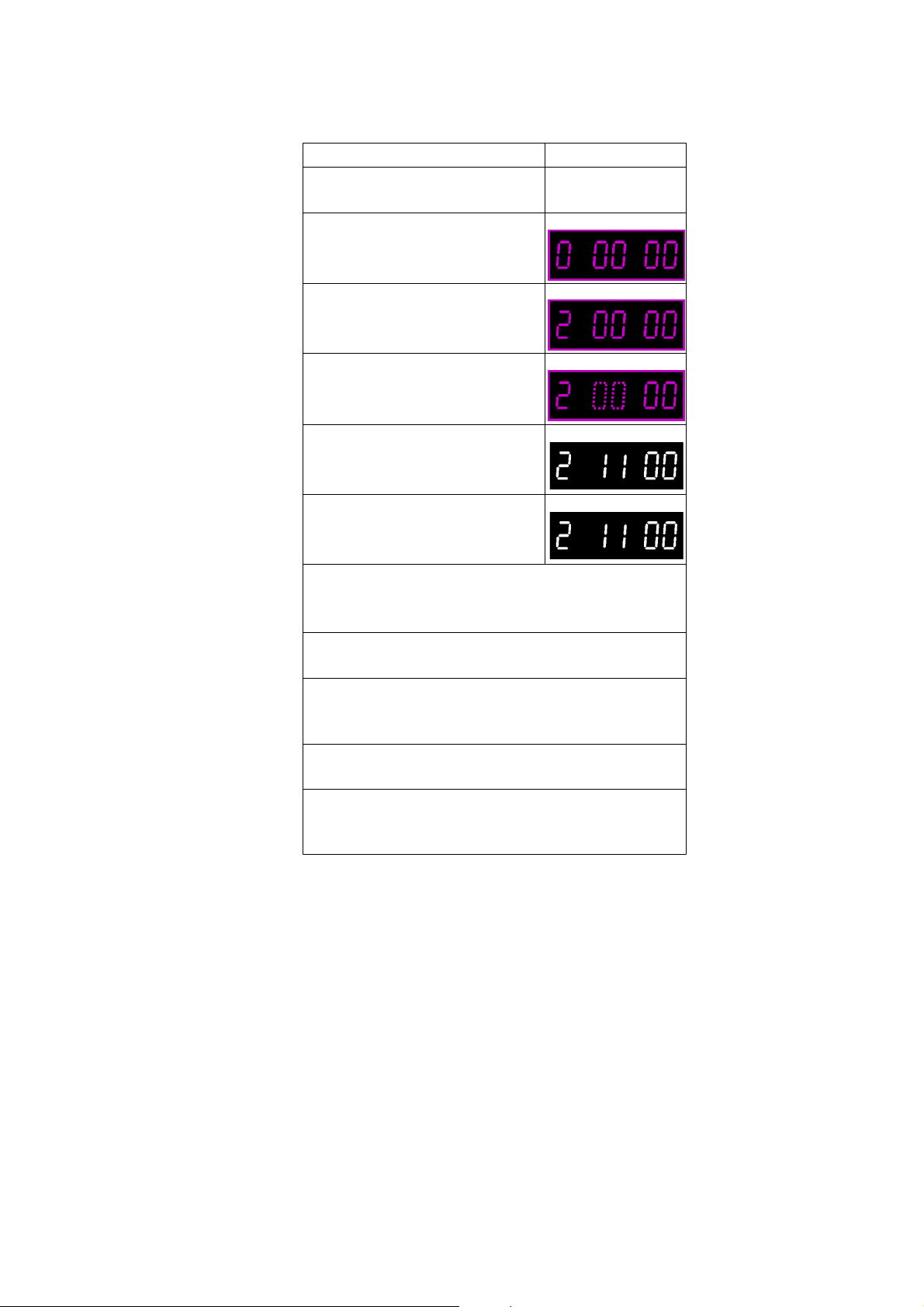
PROCEDURES FIP DISPLAY
Input the Video sweep signal.
(See Fig.E1)
Press the FF and EJECT Keys
simultaneously for 3 seconds.
Press the FF and EJECT Keys
simultaneously twice.
Press the EJECT key for 3
seconds.
Press the CH UP and/or CH
DOWN key until "11" is
displayed on FIP.
Insert the Self-recorded tape
and playback it. (SP/LP/EP
mode)
Connect the Oscilloscope to:
*CH1....Video Out (TW3002).
*CH2....V.FREQ.(TW6002)
Press the "4" key on the remote controller.
(Confirm that TW6002 becomes high(5V)).
Adjust the Frequency response by pressing the
"2"(increase) and/or "8"(decrease) key on the
Remote Controller. (See Fig.E2)
Store the Adjusted value by pressing the "5" key
on the Remote Controller.
Release the Service mode by pressing the EJECT
and FF keys simultaneously in 6 times until the FIP
becomes normal indication.
Fig. E5
3.3.7. LOCATION OF TEST POINTS & CONTROLS

http://cxema.ru
3.3.8. CIRCUIT BOARD LAYOUT
4. ABBREVIATIONS
 Loading...