


ORDER NO. MOD 0106244C1
E2
Service Manual
Microwave Oven
NN-S251WL
NN-S251BL
Specifications
ITEM |
APH |
|
|
Power Source |
120 V AC, 60 Hz |
|
|
Power Requirement: |
13.5 Amps, 1,550 W |
|
|
Output: |
1000 W: Full Power (IEC 60705) |
|
|
Microwave Frequency: |
2,450 MHz |
|
|
Timer: |
99 min. 99 sec. |
|
|
Outside Dimensions: |
2915/16"(W) X 167/16"(H) X 153/8"(D) |
|
760mm(W) X 418mm(H) X 385mm(D) |
|
|
Oven Cavity Dimensions: |
197/8"(W) X 815/16"(H) X 143/16"(D) |
|
505mm(W) X 227mm(H) X 360mm(D) |
|
|
Weight: |
Approx. 52 lbs (23.5 kg) |
Specifications subject to change without notice.
 2001 Matsushita Electric Industrial Co., Ltd. All rights reserved. Unauthorized copying and distribution is a violation of law.

SAFETY PRECAUTIONS
w WARNING
This service information is designed for experienced repair technicians only and is not designed for use by the general public. It does not contain warnings or cautions to advise non-technical individuals of potential dangers in attempting to service a product.
Products powered by electricity should be serviced or repaired only by experienced professional technicians. Any attempt to service or repair the product or products dealt with in this service information by anyone else could result in serious injury or death.
WARNING
1.This product should be serviced only by trained, qualified personnel.
2.Though this product has been manufactured in compliance with:
“Federal Performance Standard 21 CFR Subchapter J”(D.H.H.S): U.S.A. models or “Radiation Emitting Devices Act”(Health and Welfare Canada):Canadian models
it is very important all repairs should be made in accordance with procedures described in this manual to avoid being exposed to excessive microwave radiation.
3.Check for radiation leakage before and after every servicing according to the “procedure for measuring radiation leakage.”
4.If the unit cannot be repaired on site, advise the customer not to use until unit is repaired.
5.Any serviceman who learns of any accident pertaining to microwave radiation leakage including the oven operating with open door should immediately notify the appropriate address listed below and Center for Devices and Radiological Health, DHHS.
IN U.S.A. |
Panasonic Services Company |
IN PUERTO RICO |
PSC |
(PASC) |
50 Meadowland Parkway, |
(PSC) |
San Gabriel Industrial Park |
|
Secaucus, New Jersey 07094 |
|
65th Infantry Ave. Km.9.5 |
|
Attention: Technical Service Division. |
|
Carolina, Puerto Rico 00985 |
|
(201)348-7000 |
|
(787)750-4300 |
6.There are special components used in the microwave oven which are important for safety. These parts are marked with a w on the replacement parts list. It is essential that these critical parts should be replaced only with the manufacture’s specified parts to prevent microwave leakage, shock, fire, or other hazards. Do not modify the orginal design.
PRECAUTIONS TO BE OBSERVED BEFORE AND DURING SERVICING TO AVOID POSSIBLE EXPOSURE TO EXCESSIVE MICROWAVE ENERGY
(A)Do not operate or allow the oven to be operated with the door open.
(B)Make the following safety checks on all ovens to be serviced before activating the magnetron or other microwave source, and make repairs as necessary:
(1)Interlock operation
(2)Proper door closing
(3)Seal and sealing surfaces (arcing, wear, and other damage)
(4)Damage to or loosening of hinges and latches.
(5)Evidence of dropping or abuse
(C)Before turning on microwave power for any service test or inspection within the microwave generating
compartments, check the magnetron, waveguide or transmission line, and cavity for proper alignment, integrity and connections.
(D)Any defective or misadjusted components in the interlock, monitor, door seal, and microwave generation and transmission systems shall be repaired, replaced, or adjusted by procedures described in this manual before the oven is released to the owner.
(E)A microwave leakage check to verify compliance with the Federal Performance Standard should be performed on each oven prior to release to the owner.
FOREWORD
Read this Manual carefully. Failure to adhere to or observe the information in this Manual may result in exposing yourself to the Microwave Energy normally contained within the oven cavity.
TABLE OF CONTENTS |
|
|
(Page) |
SAFETY PRECAUTIONS ......................................................................................................... |
Inside front page |
SPECIFICATIONS.......................................................................................................................................... |
1-1 |
CAUTIONS ..................................................................................................................................................... |
2-1 |
INSTALLATIONS............................................................................................................................................ |
3-1 |
FEATURE DIAGRAM ..................................................................................................................................... |
4-1 |
CONTROL PANEL ......................................................................................................................................... |
4-2 |
OVERALL CIRCUIT DIAGRAM...................................................................................................................... |
5-1 |
SCHEMATIC DIAGRAM......................................................................................................................... |
5-1 |
MATRIX CIRCUIT FOR TOUCH KEY BOARD ...................................................................................... |
5-2 |
GENERAL INFORMATION FOR SERVICE ................................................................................................... |
6-1 |
GENERAL PRECAUTIONS IN USE ...................................................................................................... |
6-1 |
TRIAL OPERATION ............................................................................................................................... |
6-1 |
FEATURES AND SPECIFICATIONS FEATURES................................................................................. |
6-1 |
SERVICE INFORMATION ............................................................................................................................. |
7-1 |
PRECAUTIONS AND REPAIR SERVICE TIPS ..................................................................................... |
7-1 |
PROCEDURE FOR MEASURING MICROWAVE ENERGY LEAKAGE................................................ |
7-2 |
POWER OUTPUT MEASUREMENT ..................................................................................................... |
7-3 |
DISASSEMBLY INSTRUCTIONS .......................................................................................................... |
7-4 |
INTERLOCK SYSTEM .......................................................................................................................... |
7-12 |
INTERLOCK CONTINUITY TEST .......................................................................................................... |
7-14 |
TEST AND CHECKOUT PROCEDURES AND TROUBLE SHOOTING................................................ |
7-15 |
A. TEST PROCEDURES................................................................................................................ |
7-15 |
B. CHECKOUT PROCEDURES..................................................................................................... |
7-18 |
C. TROUBLE SHOOTING .............................................................................................................. |
7-21 |
SCHEMATIC DIAGRAM OF PCB .................................................................................................................. |
8-1 |
PRINTED CIRCUIT BOARD .................................................................................................................. |
8-2 |

SPECIFICATIONS
Rated Power Consumption |
1,550W maximum (Microwave oven+Cook top lamps+Ventilation fan) |
||
Frequency |
2,450 MHz ± 50 MHz |
||
Power Supply |
120 VAC, 60 Hz |
||
Rated Current |
13.5 Amp. |
|
(Microwave oven+Cook top lamps+Ventilation fan) |
|
|||
Magnetron Cooling |
Forced Air Cooling |
||
Rectification |
Rectification Voltage Double Half-Wave |
||
Door Sealing |
Choke System |
||
Safety Devices |
Oven Cavity Thermostat: |
||
|
Open at 90°C + 5°C |
||
|
Fuse(20A) |
||
|
Primary Interlock Switch |
||
|
Secondary Interlock Switch |
||
|
Interlock Monitor |
||
Magnetron |
2M214-39F |
||
High Voltage Capacitor |
Capacitor: 1.0µF, 2.1 KV AC |
||
High Voltage Diode |
Diode; 350mA, 9.0 KV |
||
Cook top Lamp |
125 V, 30 W |
||
Cavity Lamp |
125 V, 30 W |
||
Timer |
Digital, up to 99 mim. 99 sec. (in each cooking stage) |
||
Tray |
Tempered Safety Glass |
||
Overall Dimensions |
2915/16”(W)x167/16”(H)x153/8”(D) |
||
Oven Cavity Size |
197/8”(W)x815/16”(H)x143/16”(D) |
||
Effective Capacity of Oven Cavity |
1.5 Cu.ft. |
||
Accessories |
Owner’s Manual & Cooking Guide, Installation Manual, |
||
|
Exhaust Adapter, Exhaust Damper, Mounting Kit and Two |
||
|
Filters, Rotating Ring Assembly. |
||
1-1
CAUTIONS
Unlike other appliances, the microwave oven is high-voltage and high-current equipment. Though it is free from danger in ordinary use, extreme care should be taken during repair.
•DO NOT operate on a 2-wire extension cord during repair and use.
•NEVER TOUCH any oven components or wiring during operation.
•BEFORE TOUCHING any parts of the oven, always remove the power plug from the outlet.
•For about 30 seconds after the oven stops, an electric charge remains in the high voltage capacitor. When replacing or checking, you must discharge the high voltage capacitor by shorting across the two terminals with an insulated screwdriver.
Chassis Ground
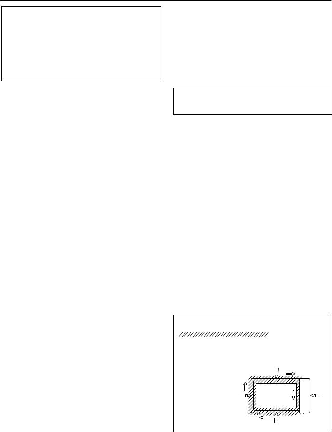
NOTE: Touch chassis first then snort to the capacitor terminals.
•Remove your watches whenever working close to or replacing the Magnetron.
•DO NOT touch any parts of the control panel circuit. A resulting static electric discharge may damage this P.C.B.
•NEVER operate the oven with no load.
•NEVER injure the door seal and front plate of the oven cavity.
•NEVER put iron tools on the magnetron.
•NEVER put anything into the latch hole and the interlock switches area.
MICROWAVE RADIATION
Personnel should not be exposed to the microwave energy which may radiate from the magnetron or other microwave generating device if it is improperly used or connection. All input and output microwave connections, waveguide, flange, and gasket must be secure never operate the device without a microwave energy absorbing load attached.
Never look into an open waveguide or antenna while the device is energized.
•Proper operation of the microwave oven requires that the magnetron be assembled to the waveguide and cavity. Never operate the magnetron unless it is properly installed.
•Be sure that the magnetron gasket is properly installed around the dome of the tube whenever installing the magnetron.
ANTENNA
Gasket
COOLING FIN
FILAMENT
TERMINALS
MAGNETRON
CHASSIS GROUND
MAGNETRON
THE OVEN IS TO BE SERVICED ONLY BY PROPERLY QUALIFIED SERVICE PERSONNEL.
2-1

INSTALLATIONS
BEFORE YOU BEGIN, READ THE FOLLOWING INSTRUCTIONS COMPLETELY AND CAREFULLY.
PRECAUTIONS ON INSTALLATION
A.Plug the power supply cord into a 120V AC, 60Hz, single-phase power source with a capacity of 15A or 20A.
B.Avoid placing the unit in a location where there is direct heat or splashing water.
C.Install the unit on the mounting plate firmly.
D.Place the unit as far away as possible from TV, radio, etc. to prevent interference.
GROUNDING INSTRUCTIONS
For personal safety, this appliance must be fully grounded at all times.
In the event of an electrical short circuit, grounding reduces the risk of electrical shock.
The plug must be plugged into an outlet that is properly installed and grounded.
CAUTION
This unit is equipped with a 3-prong plug for your safety. If the wall outlet is a grounded 3-hole type, the unit will be grounded automatically.
Plug with Ground
Prong
Properly Polarized
and Grounded
Outlet
WARNING
Improper use of the grounding plug can result in a risk of electric shock.
Do not, under any circumstances, cut or remove the third ground prong from the power cord plug.
3-1

FEATURE DIAGRAM
Identification Plate & Menu |
Label |
|
See-through Oven Window |
Glass Tray |
Oven Air Vent |
Door Handle
Cover
(do not remove)
Door Safety |
|
Lock System |
Control Panel |
Cooktop Light
Grease Filter
4-1

CONTROL PANEL
1.Display Window : The Display includes a clock and indicators to tell you time of day, cooking time settings and cooking functions selected.
2.Auto Defrost Pad : Meat, poultry, fish. Touch on pad to select food type and defrost food by weight.
3.Auto Reheat Pad : Touch this pad to reheat dinner plate, soup/sause, casserole, roll/muffin.
4.Auto Cook Pad : Touch this pad to cook vegetables, rice, or casseroles.
5.Cook Time Pad : Touch this pad to set a cooking time.
6.Power Level Pad : Touch this pad to select a cooking power level.
7.Number Pads : Touch number pads to enter cooking time, power level, quantities or weights.
8.Timer Pad : Touch this pad to set the kitchen timer.
9.Clock Pad : Touch this pad to enter the time of day.
10.Timer Off Pad : Touch this pad to stop timer function.
11.Function Pad : Touch this pad to change the oven’s default settings for sound, clock, display speed, defrost weight, and demo mode operations.
12.Quick Min Pad : Touch this pad to set and start quickly at 100% power level.
13.Stop/Reset Pad : Touch this pad to stop oven or clear all entries.
14.Start Pad : Touch this pad to start a function. If you open the door after oven begins to cook, retouch START.
15.Light On/Night/Off Pad : Touch this pad to turn on the cooktop/countertop light.
16.Fan High/Low/Off Pad : Touch this pad to turn the fan on or off.
17.Menu Pads
4-2

OVERALL CIRCUIT DIAGRAM
SCHEMATIC DIAGRAM
5-1
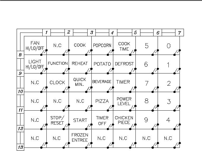
MATRIX CIRCUIT FOR TOUCH KEY BOARD
5-2
GENERAL INFORMATION FOR SERVICE
GENERAL PRECAUTIONS IN USE
A.Never operate the unit when it is empty.
Operating the oven with no load may shorten the life of the magnetron. Whenever cooking dry foods (dried fish, bread, etc.) or a small amount of food, be sure to put a glass of water into the cooking compartment. The glass turntable may become hot after operating, be careful when touching it.
B.Aluminum foil should be avoided because it will disrupt cooking and may cause arcing. However, small pieces may be used to cover some parts of food to slow the cooking. Any aluminum foil used should never be closer than 2.5 cm to any side wall of the oven.
TRIAL OPERATION
After installation, the following sequences and results should be checked carefully.
A.Put a container filled with water (about 1 liter) into the oven, and close the door tightly.
B.Set cooking time for 10 minutes by touching “1” and then “0” three times. “1, 0, 0, 0” appears in the display window.
C.Touch the START key.
Make sure the cavity light comes on. The unit will begin cooking and the display window will show the time counting down by seconds.
D.After about 5 minutes, make sure the primary interlock switch, the secondary interlock switch and the interlock monitor switch operate properly by opening and closing the door several times. Touch the START key each time the door is closed.
E.Continue operating the unit. Four long beep sound signal is heard when the time is up. The unit will shut off automatically.
F.Confirm the water is hot.
G.Finally, measure the output power according to “POWER OUTPUT MEASUREMENT” on page 7-3.
FEATURES AND SPECIFICATIONS FEATURES
A.The safety systems incorporated in this model are:
(1)Primary interlock switch
(2)Secondary interlock switch
(3)Interlock monitor switch
(4)Choke system
(5)Magnetron thermal fuse
(6)Oven cavity thermostat
(Note: This thermostat located on the oven cavity will open and stop the unit from operation only if a high temperature is reached, such as, a fire created by overcooking food.)
B.Any one of 10 power output levels ranging 100W to 1000W can be selected by the touch control and electronic computer system.
6-1

SERVICE INFORMATION
PRECAUTIONS AND REPAIR SERVICE TIPS
PRELIMINARY
A.SINCE NEARLY 2,100 VOLTS EXISTS IN SOME CIRCUITS OF THIS UNIT REPAIRS SHOULD BE CARRIED OUT WITH GREAT CARE.
The filament leads of magnetron carry High Voltage with respect to ground. Extreme caution must be exercised. Never plug the unit into a power source to determine which component is defective in high voltage section.
B.TO AVOID POSSIBLE EXPOSURE TO MICROWAVE ENERGY LEAKAGE, THE FOLLOWING PRECAUTIONS MUST BE TAKEN
BEFORE SERVICING.
(1)Before the power is applied:
(a)Make sure the primary interlock switch, the secondary interlock switch and the interlock monitor switch operate properly by opening and closing the door several by opening and closing the door several times.
(b)Make sure the perforated screen and the dielectric choke of the door are correctly and firmly mounted.
(2)After power is applied:
(a)Make sure the interlock switch mechanism is operating properly by opening and closing the door.
(b)Check microwave energy leakage must bebelow the limit of 5 mW/cm2.
(All service adjustments should be made for minimum microwave energy leakage readings).
(3)Do not operate the unit until it is completely repaired, if any of the following conditions exist. The unit must not be operated.
(a)The door does not close firmly.
(b)The hinge is broken.
(c)The door seal is damaged.
(d)The door is bent or warped, or there is any other visible damage on the unit that may cause microwave energy leakage.
NOTE: Always keep the seal clean.
(e)Make sure that there are no defective parts in the interlock mechanism.
(f)Make sure that there are no detective parts
in the microwave generating and transmission assembly (especially waveguide).
(4)The following items should be checked after the unit is repaired:
(a)The interlock monitor switch is connected correctly and firmly.
(b)The magnetron gasket is properly positioned and mounted.
(c)The waveguide and the oven cavity are intact. (no microwave energy leakage)
(d)The door can be properly closed and the safety switches work properly.
(e)The unit must stop when the door is opened or the time is up.
The unit must not be operated with any of the above components removed or by-passed.
7-1
PROCEDURE FOR MEASURING MICROWAVE ENERGY LEAKAGE
WARNING
Check for radiation leakage after every servicing. Should the leakage be more than 2 mW/cm2 inform PASC immediately. After repairing or replacing any radiation safety device, keep a written record for future reference, as required by D.H.H.S. regulation. This requirement must be strictly observed. In addition, the leakage reading must be recorded on the service repair ticket while in the customer’s home.
NOTE: The U.S. Government standard is 5mW/cm2 while in the customer s home. 2mW/cm2 stated here is our own voluntary standard.
1.Equipment
•Electromagnatic radiation monitor
•Glass thermometer 212°F or 100°C
•600cc glass beaker
2.Procedure for measuring radiation leakage
Note before measuring.
(1)Do not exceed meter full scale deflection. Leakage monitor should initially be set to the highest scale.
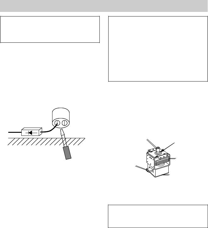
(2)To prevent false readings the test probe should be held by the grip portion of the handle only and moved along the shaded area in Figure no faster than 1 inch/sec (2.5cm/sec).
(3)Leakage with the outer panel removed ...... less than 5mW/cm2.
(4)Leakage for a fully assembled oven with door normally closed ...... less than 2mW/cm2 (1mW/cm2 for Canada).
(5)Leakage for a fully assembeld oven [Before the latch switch (primary) is interrupted] while pulling the door ...... less than 2mW/cm2.
(A)Pour 275°±15cc (9ozs°±1/2oz) of 20°±5°C (68°±9°F) water in a beaker which is graduated to 600cc , and place in the center of the oven.
(B)Set the radiation monitor to 2450MHz and use it following the manufacturer’s recommended test procedeur to assure correct results.
(C)When measuring the leakage, always use the 2 inch (5cm) spacer supplied with the probe.
(D)Tap the start pad or set the timer and with the magnetron oscillating, measure the leakage by holding the probe perpendicular to the surface being measured.
(1)Measurement with the outer panel removed.
Whenever you replace the magnetron, measure for radiation leakage before the outer panel is installed and after all necessary components are replaced or adjusted. Special care should be taken in measuring around the magnetron.
WARNING
Avoid contacting any high voltage parts.
(2)Measurements with a fully assembled oven.
After all components, including outer panel are fully assembled, measure for radiation leakage around the door periphery, the door viewing window, the exhaust opening and air inlet openings.
3.Record keeping and notification after measurement
(A)After any adjustment or repair to a microwae oven, a leakage reading must be taken. Record this leakage reading on the repair ticket even if it is zero.
A copy of this repair ticket and the microwave leakage reading should be kept by repair facility.
(B)Should the radiation leakage be more than 2mW/cm2 after determining that all parts are in good condition, functoning properly, and genuine replacement parts as listed in this manual have been used, immediately notify PASC.
4.At least once a year, have the radiation monitor checked for calibration by its manufacturer.
Move probe along shaded area.
Probe scanning speed
Less than 2.5 cm/sec. ( 1 in/sec)
7-2

MEASUREMENT WITH THE OUTER CASE REMOVED
(1)When you replace the magnetron, measure for microwave energy leakage before the outer case is installed and after all necessary components are replaced or adjusted. Special care should be taken in measuring the following parts.
-Around the magnetron
-The waveguide
WARNING: AVOID CONTACTING ANY HIGH VOLTAGE PARTS.
MEASUREMENT WITH A FULLY
ASSEMBLED OVEN
(1)After all components, including the outer panels, are fully assembled, measure for microwave energy leakage around the door viewing window, the exhaust opening and air inlet openings.
(2)Microwave energy leakage must not exceed the values prescribed below.
NOTES: Leakage with the outer panels removed - less than 5 mW/cm2.
Leakage for a fully assembled oven (“Before the latch switch (primary) is interrupted”) with the door in a slightly opened position - less than 2 mW/cm2.
NOTE WHEN MEASURING
(1)Do not exceed meter full scale deflection.
(2)The test probe must be removed no faster than 1 inch/sec (2.5cm/sec) along the shaded area, otherwise a false reading may result.
(3)The test probe must be held with the grip portion of the handle. A false reading may result if the operator’s hand is between the handle and the probe.
(4)When testing near a corner of the door, keep the probe perpendicular to the surface making sure the probe horizontally along the oven surface, this may possibly cause probe damage.
RECORD KEEPING AND NOTIFICATION AFTER MEASUREMENT
(1)After adjustment and repair of any microwave energy interruption or microwave energy blocking device, record the measured values for future reference. Also enter the information on the service invoice.
(2)Should the microwave energy leakage not be more than 2 mW/cm2 after determining that all parts are in good condition, functioning properly and genuine replacement parts which are listed in this manual have been used.
(3)At least once a year, have the electromagnetic energy leakage monitor checked for calibration by its manufacturer.
POWER OUTPUT MEASUREMENT
(1)Microwave power output measurement is made with the microwave oven supplied at its rated voltage and operated at its maximum microwave power setting with a load of (1000±5) g of potable water.
(2)The water is contained in a cylindrical borosilicate
glass vessel having a maximum material thickness of 1/8” (3 mm) and an outside diameter of approximately 7.6” (190mm).
(3)The oven and the empty vessel are at ambient temperature prior to the start of the test.
(4)The initial temperature (T1) of the water is (10±2)°C (50°F) It is measured immediately before the water is added to the vessel. After addition of the water to the vessel, the load is immediately placed on the center of the turntable which is in the lowest position and the microwave power switched on.
(5)The time T for the temperature of the water to rise by a value ∆ T of (10±2)°K is measured, where T is the time in seconds and ∆ T is the temperature rise. The initial and final water temperatures are selected so that the maximum difference between the final water temperature and the ambient temperature is 5°K.
(6)The microwave power output P in watts is calculated from the following formula :
P =
4187 x (∆ T)
T
is measured while the microwave generator is operating at full power. Magnetron filament heat-up time is not included. (about 3 sec)
(7)The water is stirred to equalize temperature throughout the vessel, prior to measuring the final water temperature.
(8)Stirring devices and measuring instruments are selected in order to minimize addition or removal of heat.
WATER LOAD
TURNTABLE
NOTES: For simple test of microwave power output, conduct it by heating one litter water for one minute, minimum temperature rise should be 15.4°F(8.6°C)
7-3
 Loading...