


NN-L530BF
Service Manual
ORDER NO. SIMMC 0001002C1
E1
Microwave Oven
© 2000 Shanghai Matsushita Microwave
Oven Co.,Ltd
All rights reserved. Unauthorized copying
and distribution is a violation of law.
MODELS APH CPH
USA Canada
®
Specifications:
Power Source:
Power Requirement:
Output(IEC705-88):
Microwave Frequency:
Timer:
Outside Dimensions:
Oven Cavity Dimensions:
Weight:
Output power:IEC705-88 Test Procedure
Specifications subject to change without notice.
Specifications for APH :
Model:
*
120V AC Single Phase, 60Hz
*
2450MHz
*
99min.99sec
*
20
”(518mm)(W)
O
16
”(407mm)(D)
O
11”(301mm)(H)
*
14
”(375mm)(W)
O
15
”(386mm)(D)
O
8
”(225mm)(H)
*
26.5 lbs. (12.0kg)
1370W
1370W
1370W 1370W
1300W 1300W 1100W 1000W
NN-S560BF/WF NN-S550BF/WF NN-S540BF/WF NN-L530BF/WF
Specifications:
Power Source:
Power Requirement:
Output(IEC705-88):
Microwave Frequency:
Timer:
Outside Dimensions:
Oven Cavity Dimensions:
Weight:
Output power:IEC705-88 Test Procedure
Specifications subject to change without notice.
Specifications for CPH:
Model:
*
120V AC Single Phase, 60Hz
*
2450MHz
*
99min.99sec
*
20
”(518mm)(W)
O
16
”(407mm)(D)
O
11”(301mm)(H)
*
14
”(375mm)(W)
O
15
”(386mm)(D)
O
8
”(225mm)(H)
*
26.5 lbs. (12.0kg)
1370W 1370W 1370W 1370W 1370W
1200W 1100W 1100W 1100W 1000W
NN-S560BF/WF
NN-S540BF/WF
NN-L530WF NN-L520WF NN-S510WF
NN-S560BF/WF
NN-S550BF/WF
NN-S540BF/WF
NN-L530BF
NN-L530WF
NN-L520WF
NN-S510WF
*
RPH Model refer to the last page.

WARNING
CONTENTS
(Page) (Page)
-1-
FEATURE CHART ...........................................................................3 DISASSEMBLY AND PARTS REPLACEMENT PROCEDURE ............... 13
CONTROL PANEL ...........................................................................3 COMPONENT TEST PROCEDURE ........................................................16
OPERATION AND DIGITAL PROGRAMMER MEASUREMENTS AND ADJUSTMENTS ............................................... 18
CIRCUIT TEST PROCEDURE ........................................................5 PROCEDURE FOR MEASURING MICROWAVE ENERGY LEAKAGE... 19
SCHEMATIC DIAGRAMS ............................................................... 7 TROUBLESHOOTING GUIDE .................................................................20
DESCRIPTION OF OPERATING SEQUENCE ...............................9 EXPLODED VIEW AND PARTS LIST ...................................................... 24
CAUTIONS TO BE OBSERVED WHEN TROUBLESHOOTING ....11 SCHEMATIC DIAGRAM &
PARTS LIST OF DIGITAL PROGRAMMER CIRCUIT ............................. 25
PRECAUTIONS TO BE OBSERVED BEFORE AND
DURING SERVICING TO AVOID POSSIBLE EXPOSURE
TO EXCESSIVE MICROWAVE ENERGY
(A) Do not operate or allow the oven to be operated with the
door open.
(B) Make the following safety checks on all ovens to be serviced
before activating the magnetron or other microwave source,
and make repairs as necessary:
(1) Interlock operation
(2) Proper door closing
(3) Seal and sealing surfaces (arcing, wear, and other
damage)
(4) Damage to or loosening of hinges and latches.
(5) Evidence of dropping or abuse
(C) Before turning on microwave power for any service test or
inspection within the microwave generating compartments,
check the magnetron, waveguide or transmission line, and
cavity for proper alignment, integrity and connections.
(D) Any defective or misadjusted components in the interlock,
monitor, door seal, and microwave generation and trans-
mission systems shall be repaired, replaced, or adjusted
by procedures described in this manual before the oven is
released to the owner.
(E) A microwave leakage check to verify compliance with the
Federal Performance Standard should be performed on
each oven prior to release to the owner.
WARNING
This service information is designed for experienced repair technicians only and is not designed for use by the general public. It does not
contain warnings or cautions to advise non-technical individuals of potential dangers in attempting to service a product.
Products powered by electricity should be serviced or repaired only by experienced professional technicians. Any attempt to service or repair
the product or products dealt with in this service information by anyone else could result in serious injury or death.
>
1.This product should be serviced only by trained, qualified personnel.
2.Though this product has been manufactured in compliance with:
“Federal Performance Standard 21 CFR Subchapter J”(D.H.H.S): U.S.A. models
or “Radiation Emitting Devices Act”(Health and Welfare Canada): Canadian models
it is very important all repairs should be made in accordance with procedures described in this manual to avoid being exposed
to excessive microwave radiation.
3.Check for radiation leakage before and after every servicing according to the “procedure for measuring radiation leakage.”
4.If the unit cannot be repaired on site, advise the customer not to use until unit is repaired.
5.Any serviceman who learns of any accident pertaining to microwave radiation leakage including the oven operating with
open door should immediately notify the appropriate address listed below and Center for Devices and Radiological Health,
DHHS.
IN U.S.A. Panasonic Services Company IN PUERTO RICO PSC
(PASC) 50 Meadowland Parkway, (PSC) San Gabriel Industrial Park
Secaucus, New Jersey 07094 65th Infantry Ave. Km.9.5
Attention: Technical Service Division. Carolina, Puerto Rico 00985
(201)348-7000 (787)750-4300
IN CANADA Panasonic Canada Inc.
(PCI) 5770 Ambler Drive, Mississauga,
Ontario, L4W2T3
(905)624-5010
6.There are special components used in the microwave oven which are important for safety. These parts are marked with
a on the replacement parts list. It is essential that these critical parts should be replaced only with the manufacture’s
specified parts to prevent microwave leakage, shock, fire, or other hazards. Do not modify the orginal design.
>
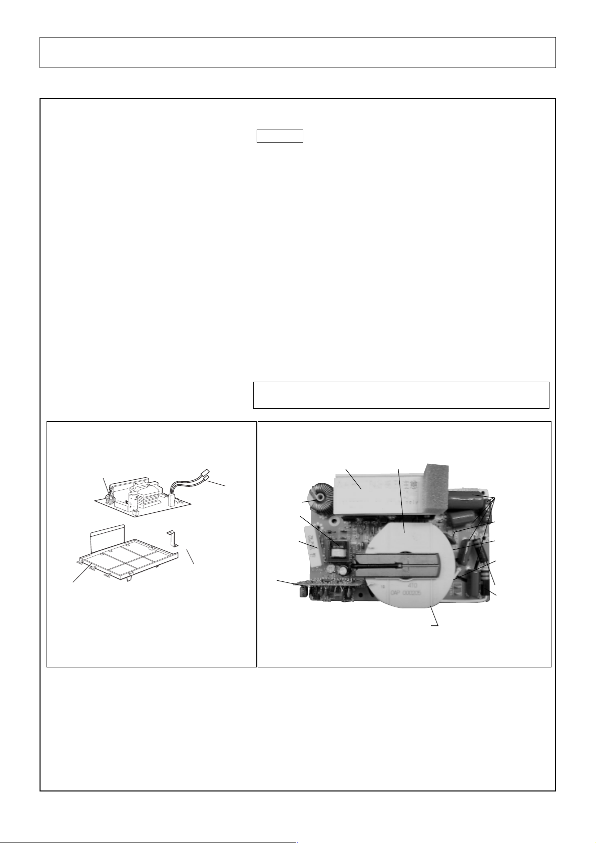
DANGER OF HIGH VOLTAGE AND HIGH TEMPERATURE (HOT/LIVE) OF THE INVERTER POWER SUPPLY (U)
INVERTER WARNING
This Inverter board looks like a regular PCB. However, this PCB drives the magnetron tube with extremely high voltage
and high current.
IT HAS: 1. Very high voltage and high current circuits.
It functions the same as the high voltage transformer and high voltage capacitor in ordinary microwave ovens.
2. Aluminum heat sink is energized with very high voltages and high heat energy.
3. Very high voltage may remain in circuitry even when oven is off. High voltage may remain in the capacitors
on the board.
DO NOT:
1. Do not touch circuitry because it has very hot (high voltage) circuitry. Even when replacing board, extreme
care should be taken to avoid possible electric shock hazards. High voltage may remain in circuit.
2. Do not touch aluminum heat sink because it is very hot in high voltage and also very hot in high heat energy.
3. Do not try to adjust or tamper with preset volume on the Inverter board because it is very dangerous to
adjust without proper test equipment.
4. Do not test oven while Inverter grounding plate or screws are loose. It is very dangerous to operate H.V.
Inverter Circuit (U) with loose mounting screws or if improperly grounded.
5. For USA only:
Do not try to repair Inverter PCB because it is very dangerous to repair it. Replace as whole High Voltage
Inverter Circuit unit and return fully re-packed with original shipping box and shipping materials.
INVERTER POWER SUPPLY DIAGRAM
NEW HV
- 2 -
*
*
*
*
*
HEAT SINK
(RECTIFIER BRIDGE)
CHOKE COIL
CURRENT
TRANSFORMER
SAND BAR
RESISTOR
HIGH VOLTAGE
TRANSFORMER
PCB
FILM CAPACITORS
VARISTOR
PRIMARY WINDINGS
SECONDARY
WINDINGS
HIGH VOLTAGE
DIODES
DO NOT TOUCH
LEAD
WIRE
GROUNDING
PLATE
*
4
INVERTER
SUPPORT
BRACKET OF ORIFICE
H.V INVERTER(U)
*
3
1
2
5
7
11
16
17
4
aa
aa
a
9
12
3
8
6
10
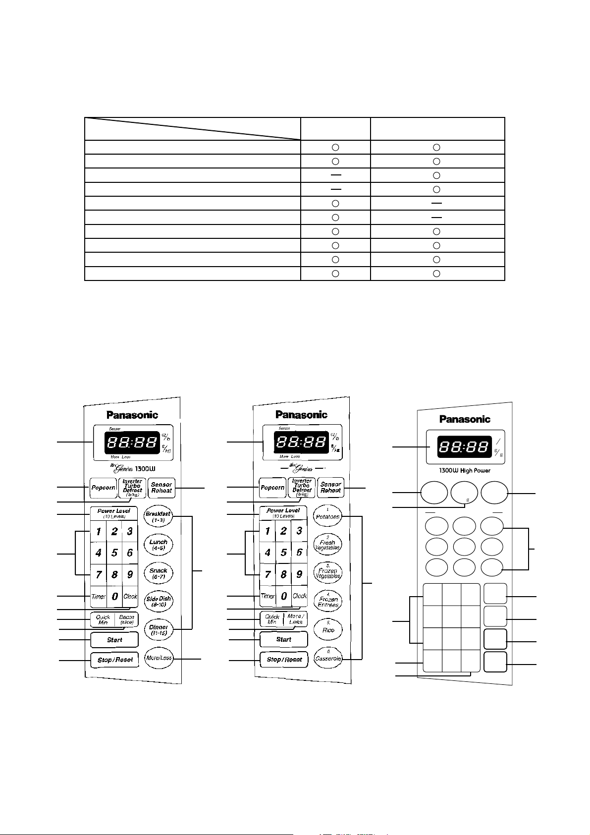
FEATURE CHART
- 3 -
CONTROL PANEL
FEATURE
Three Stage Cooking
Inverter Turbo Defrost
Auto Reheat
Inverter Auto Cook
Sensor Reheat
Sensor Cook
Quick Min
Popcorn
Timer
Digital Clock
MODEL
NN-S550WF NN-S540WF NN-S510WF
NN-S520WFNN-S530WF
NN-S560WF
NN-S560(CPH)
NN-S560(APH)
1
2
5
7
11
16
17
3
8
6
12
9
NN-S550
7
1
2
4
bb
bb
b
17
3
6
16
11
5
8
10
k
lb
oz
Popcorn
Inverter
Turbo
Defrost
(lb/k )
Auto
Reheat
(1-4servings)
Inverter Auto Cooking
Power
Level
(10 Levels)
Quick
Min
Start
Stop/
Reset
123
654
789
Clock
0
Timer
Froz.Veg.
11.
Froz.
Entrées
8.
Breakfast
(-)
13
Dinner
67
(-)
FreshVeg.
10.
Serving
/
Weight
Rice
12.
Potatoes
9.
Lunch
45
(-)
4
aa
aa
a

- 4 -
CONTROL PANEL
NN-L520
7
1
2
4b
17
3
13
6
16
11
5
8
14
15
NN-L530
1
2
4b
17
3
13
6
16
11
5
8
7
14
15
(1) Display Windows
(2) Popcorn Pad
(3) Inverter Turbo Defrost Pad
(4a) Sensor Reheat Pad
(4b) Auto Reheat Pad
(5) Power Level Pad
(6) Number Pads
(7) Timer Pad
(8) Clock Pad
(9) Sensor Cook Pad
(10) Inverter Auto Cooking Pads
(11) Quick Min Pad
(12) More /Less Pad
(13) Cooking Guide
(14) Auto Cook Pad
(15) Serving/Weight Pad
Before cooking: One tap clears your instructions.
During cooking: One tap temporarily stops the
cooking process. Another tap cancels all your
instructions and time of day or colon appears on
the display window.
(17) Stop/Reset Pad
One tap allows oven to begin functioning. If door is
opened or STOP/RESET Pad is pressed once during
oven operation, START Pad must again be pressed to
restart oven.
(16) Start Pad
5
MN-S510
7
1
2
4b
17
3
6
16
11
8
10
NN-S540
7
1
2
4b
17
3
6
16
11
5
8
10
- 5 -
OPERATION AND DIGITAL PROGRAMMER CIRCUIT TEST PROCEDURE
When you pluge the power supply cord into the wall outlet, microwave oven automatically enter into the state of lb / oz. If you want
to use g / kg state, please press Start pad after pluging the power source.
1. Press Inverter Turbo Defrost
pad.
2. Set the weight for 1 lb by press-
ing Number pads.
1 lb = 1 0
3. Press Start Pad.
4. Press Stop/Reset Pad twice.
Oven shuts off.
8. When 2nd stage cooking time has
elapsed, oven beeps 5 times and
shuts off.
Time of day or colon if set appears
in the display.
3. Inverter Turbo Defrost
OPERATION SCROLL DISPLAY
OPERATION
SCROLL DISPLAY
Time of day or colon if set appears
in the display.
4.23
1.0
1. Press Rice pad twice.
2. Press Start pad.
Cooking begins as time counts
down.
3. When cooking time has elapsed,
oven beeps 5 times and shuts off.
4. Inverter Auto Cooking
OPERATION SCROLL DISPLAY
15.00
2. Press Power Level pad once
to set High power.
(1st stage)
3. Set for 5 seconds by pressing
Number pads.
5 sec.= 5
4. Press Power Level pad 4 times
to s et Medium power.
(2nd stage)
5. Set for 1 minute by pressing
Number pads.
1 min.= 1 0 0
6. Press Start pad.
7. When 1st stage cooking time has
elapsed. Oven beeps twice and
automatically switches to 2nd
stage cooking.
OPERATION
SCROLL DISPLAY
1. Plug the power supply cord into
wall outlet.
2. Press Clock pad.
3. Enter time of day (TOD) by press-
ing appropriate Number pads.
4. Press Clock pad. TOD has now
been resistered into the digital
programmer circuit and will count
up by minutes.
2. Time Cooking for Two Stage
OPERATION SCROLL DISPLAY
1. Place a water load in the oven.
88.88
11 25
11. 25
1.0 0
P 1 0
. 5
P 5
. 5
1.0 0
1. To Set Clock
1
Time of day or colon if set appers in
the display.
1. Press Auto Cook pad.
2. Press Number pads.
(Press 3 to select Bacon)
5. Auto Cook
OPERATION
SCROLL DISPLAY
3
6

- 6 -
OPERATION SCROLL DISPLAY
3. Press Serving / Weight pad.
(Select 4. 6. 10. 14 slices)
4. Press Start pad.
When cooking time has elapsed,
Oven beeps 5 times and shuts off.
4
4.10
Times of day or colon if set appears
in the display.
OPERATION
SCROLL DISPLAY
1. Press Popcom pad five times
for 3.5 oz serving.
(Select 1.75. 2.65. 2.85. 3.0 or
3.5 oz )
2. Press Start pad.
Cooking begin as times counts
down.
When cooking time has elapsed,
Oven beeps 5 times and shuts off.
3.5
1.45
Time of day or colon if set appears in
the display.
6. Popcorn
OPERATION
SCROLL DISPLAY
1. Pour 150 15cc (4.5 1/2 ozs)
of room temperature water in a
beaker, place the beaker in the
center of the oven.
Press Breakfast pad twice.
2. Press Start pad.
3.The steam sensor detects steam
about 1.5 to 4 minutes after the
start pad is pressed.
Sensor cooking (T1) automatically
switches to cooking time(T2).
“Sensor” disappears with beep
sounds and the remainder of
cooking time appears in the display
window.
NOTE: Cooking time will vary
depending on the water
temperature, the shape of
the beaker or the Power
source Voltage.
4.When cooking time has elapsed,
Oven beeps 5 times and shuts off.
2
Time of day or colon if set appears in
the display.
7. Sensor Cooking (NN-S560WFAPH/CPH,S560BFAPH/CPH)
OPERATION SCROLL DISPLAY
1. Press Auto Reheat pad twice
for two servings.
2. Press Start pad.Auto Reheat
cycle begins time counts down.
3.When cooking time has elapsed,
Oven beeps 5 times and shuts off.
2
2.00
Time of day or colon if set appears in
the display.
8. Auto Reheat
Press
Power Level
9. Power Level
Power Level Display Window
once
twics
3 times
4 times
5 times
6 times
7 times
8 times
9 times
10 times
P 10 (HIGH)
P 9
P 8
P 7 (MED. HIGH)
P 6 (MEDIUM)
P 5
P 4
P 3 (MEDIUM-LOW)
P 2
P 1 (LOW)
P 10
P 9
P 8
P 7
P 6
P 5
P 4
P 3
P 2
P 1
OPERATION SCROLL DISPLAY
1. Press Start pad 3 times
continuously. “Child” appears in
the display.
Child
10. To set Child satety Lock
OPERATION
SCROLL DISPLAY
1. Press Start / Reset pad 3 times
continuously.
11. To Reset Child Lock
Time of day or colon if set appears in
the display.
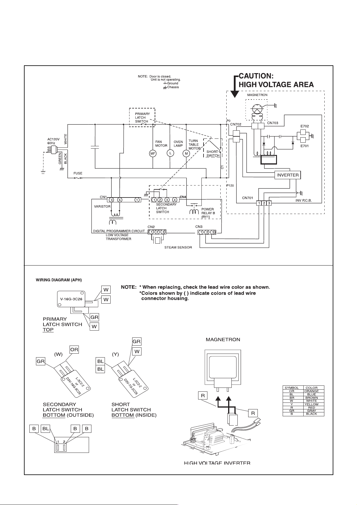
SCHEMATIC DIAGRAM (APH)
- 7 -
SCHEMATIC DIAGRAM (APH)
- 8 -
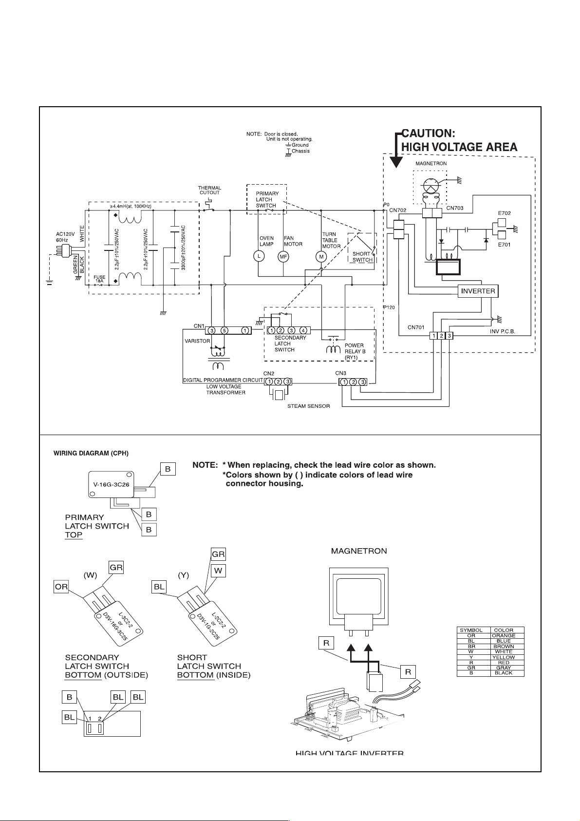
SCHEMATIC DIAGRAM (CPH)
SCHEMATIC DIAGRAM (CPH)

DESCRIPTION OF OPERATING SEQUENCE
1. Variable power cooking control
The coil of power relay B (RY1) is energized intermittently by the digital
programmer circuit, when the oven is set at any power selection except
for High power position. The digital programmer circuit controls the
ON-OFF time of power relay B contacts in order to vary the output
power of the microwave oven from ”Low” to “High” power. One
complete ON and OFF cycle of power relay B is 22 seconds. The
relation between indications on the control panel and the output of the
microwave oven is as shown in table.
NOTE: The ON/OFF time ratio does not correspond with the
percentage of microwave power since approximately 2 sec-
onds are required for heating of magnetron filament.
2. Inverter Power Supply Circuit NEW H,V
This Inverter Power Supply Circuit supplies 4,000V DC to the magnetron
tube from the line voltage,120v 60Hz AC input. functions as the H.V.
transformer, the H.V.capacitor and H.V.Diode.
1. The AC input voLtage 120V 60HZ is rectified to DC voltage immediately.
2. DC voltage will be supplied to the switching devices called IGBT. These
devices will be switched ON-OFF by the 20 to 40 kHz PWM. (pulse
width modulation) signal from the microcomputer in the DPC.
3. This drives the High voltage transformer to increase up to 2,000V AC
and approximately 3V AC by means of transformer.
4. Then the half-wave doubler voltage rectifier circuit, consisting of the
HV diodes and Capacitors, generates the necessary 4,000V DC
needed for the magnetron.
5. Output power of the magnetron tube is always monitored by the
signal output from the current transformer built into the inverter ciruit.
6. Then this signal will be fed back to the microcomputer in the DPC to
determine operating conditions and output necessary to control PWM
signal to the inverter Power Supply to control output power.
3. Inverter Turbo Defrost
When this Auto Control feature is selected and the Start Pad is tapped:
(A) The digital programer circuit determines the power level and cooking
time to complete cooking and indicates the operating state in the
display window. Table shows the corresponding cooking times for
respective serving by categories.
(B) When cooking time the display window has elapsed, the oven tums
off automatically by a control signal from the digital programmer circuit.
- 9 -
POWER SETTING
OUTPUT
POWER(%)
APPROX.
ON-OFF TIME OF
POWER RELAY B (RY1)
ON (SEC) OFF (SEC)
HIGH
MEDIUM-HIGH
MEDIUM
MEDIUM-LOW
DEFROST
100%
90%
80%
70%
60%
50%
40%
30%
20%
10%
30%
22
22
22
22
22
22
22
22
15
8
22
0
0
0
0
0
0
0
0
7
14
0
Variable Power Cooking
P10
P9
P8
P7
P6
P5
P4
P3
P2
P1
P3
Inverter Turbo Defrost
SELECTED
WEIGHT
1.0LB
6.0LB
COOKING TIME
4 min.28 sec.
25 min.00 sec.

4. Sensor Cooking (NN-S560BFAPH/CPH NN-
S560WFAPH/CPH)
Auto sensor cooking is a revolutionary way to cook by microwave
without setting a power level or selecting a time.
All that is necessary is to select an Auto Sensor Program before starting
to cook.
Understanding Auto Sensor Cooking
As the food cooks, a certain amount of steam is produced. If the food
is covered, this steam builds up and eventually escapes from the
container. In Auto Sensor Cooking, a carefully designed instrument,
called the steam sensor element, senses this escape of steam. Then,
based upon the Auto Sensor Program Selected, the unit will
automatically determine the correct power level and the proper length
of time it will take to cook the food.
NOTE: Auto Sensor Cooking is successful with the foods and
recipes found in the Auto Sensor Cooking Guide. Because
of the vast differences in food composition, items not
mentioned in the Cooking Guide should be prepared in the
microwave oven using power select and time features. Please
consult variable Power Microwave cookbook for procedures.
Explanation of the Auto Sensor Cooking process
1) During the first 10 second period there is no microwave activity,
and when calculating the T2 time by using the formula below make
sure this 10 second is subtracted from the T1 time. In other words T1
time starts at the end of the 10 second period.
2) T1 time... The total amount of time it takes the microwave oven to
switch to T2 time after the 10 second period.
3) T2 time... When the steam escapes from the cooking container placed
in the oven, the steam sensor detects it and the microprocessor cal-
culates the balance of cooking time. This T2 time is then shown in the
display and begins counting down.
Balance of cooking time (T2 time)
The balance of cooking time which is called T2 time, can be calcu-
lated by the following formula.
T2 time (in sec.)=T1 time X K factor
NOTE: Remember, the T1 time starts after the 10 second period.
The coefficient K is programmed Into the mlcroprocessor
memory and they are listed in the following tables along with
the P1 and P2 powers.
NOTE: When "More" or "Less" pad is selected, the K factor varles
resulting In T2 time to be increased or decreased.
Example of calculating the T2 time
Example 1: If the T1 time is measured to be 2 minutes and 40 seconds
after the 10 second period, and the Auto program selected is
Frozen Vegetable:
T2 = T1 X K
=2 min. and 40 sec. X 0.1
=160 sec. X 0.1
=16 sec.
5. Sensor Reheat (NN-S560BFAPH/CPH,NN-S560WF
APH/CPH)
Auto Sensor Reheat is a quick and easy way to reheat refrigerator
and room temperature foods.
Simply press the reheat pad. There is no need to select power level
and cooking time.
NOTE: The Auto Sensor Reheat process is same as Auto Sensor
Cooking process.
AUTO SENSOR COOKING/REHEAT PROCESS
Category
Frozen Vegetables
Sensor Cooking
P1
Power
HIGH
K Factor
Standard
0.1
P2
Power
LOW
- 10 -
Category
Sensor Recheat
Sensor Reheat (All Sensor Modeis)
P1
Power
HIGH
K Factor
Standard
0.1
P2
Power
LOW
 Loading...