


FX-501 Series
1
InstructIon Manual
Digital Fiber Sensor Amplier
FX-501□, FX-502□, FX-505□-C2 Series
Thank you for purchasing products from Panasonic Electric Works SUNX
Co., Ltd. Please read this Instruction Manual carefully and thoroughly for
the correct and optimum use of this product. Kindly keep this manual in a
convenient place for quick reference.
WARNING
● Never use this product as a sensing device for personnel protection.
● In case of using sensing devices for personnel protection, use prod‑
ucts which meet laws and standards, such as OSHA, ANSI or IEC
etc., for personnel protection applicable in each region or country.
1
compliance with standards
This product complies with the following standards and
regulations.
● For the EU: EMC Directive 2004/108/EC
● For the US and Canada:
ANSI/UL60947‑5‑2, CAN/CSA C22.2 No.14
● For Korea: S1‑G‑1‑2009, S2‑W‑5‑2009
* In case you require a ul listing mark or c-ul
listing mark, use a class 2 power supply unit.
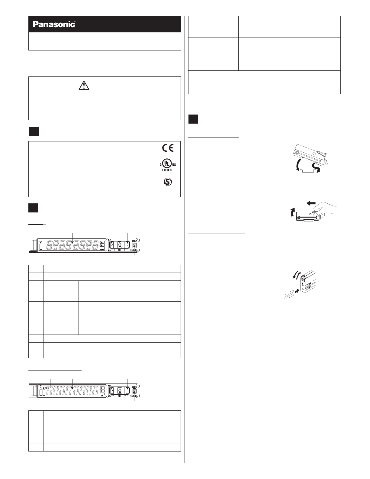
2
Part description
FX-501□
1 2 3 4
56789
1
Operation indicator for sensing output (orange)
2
Digital display (green / red)
3
UP key (+) Functions:
● Teach
● Fine adjustment of the threshold value
● Select settings
4
DOWN key (–)
5
MODE key Functions:
● Select modes
● Cancel
6
SET key Functions:
● Teach
● Save selected settings
7
Mode indicator PRO mode (yellow), see page 6
8
Mode indicator CUST (custom) mode (yellow), see page 5
9
Mode indicator L /D (Light‑ON / Dark‑ON) mode (yellow)
FX-502□ and FX-505□-C2
1 2 3 4 5
67890
1,
Sensing output 1 (lit if output is active)
● Yellow: Sensing output is selected
● Orange: Sensing output is operating
2
Sensing output 2 (lit if output is active)
● Yellow: Sensing output is selected
● Orange: Sensing output is operating
3
Digital display (green / red)
4
UP key (+) Functions:
● Teach
● Fine adjustment of the threshold value
● Select settings
5
DOWN key (–)
6
MODE key Functions:
● Select modes
● Cancel
7
SET key Functions:
● Teach
● Conrm selected settings
8
Mode indicator PRO mode (yellow)
9
Mode indicator CUST (custom) mode (yellow)
0
Mode indicator L /D (Light‑ON / Dark‑ON) mode (yellow)
* To toggle the key lock function ON/OFF, press the SET and the
MODE key together for 3 seconds.
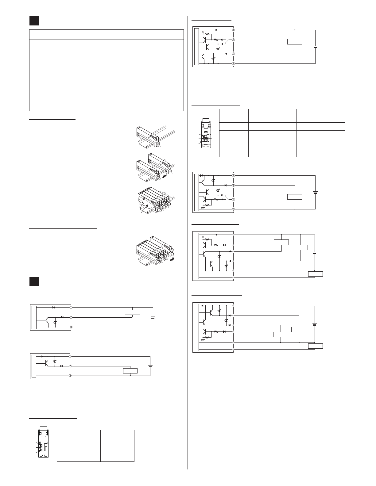
3
Mounting
Installation to a DIn rail
1. Attach the railing on the rear of the ampli‑
er to the DIN rail.
2. Push the amplier in the direction of the
arrow as illustrated so that it attaches
securely.
1.
2.
removal from a DIn rail
1. Push the amplier forward.
2. Lift the front part of the amplier up.
1.
2.
Connecting the ber cable
* The attachments to the ber cables need to be tted BEFORE
you insert the bers into the amplier. For details, refer to the
instruction manual enclosed with the bers.
1. Snap the ber lock lever 1 down as
far as it will go.
2. Insert the ber cables slowly into the
inlets until they stop (see note).
3. Return the ber lock lever to the
original position.
2.
1.
3.
1
2
3
* With the coaxial reective type ber, such as FD-G4 or FD-FM2,
insert the single core ber cable into the inlet for the emitter 2
(inlet on the amplier is labeled “P”) and the multi-core ber
cable into the inlet for the receiver 3. If they are inserted the
wrong way round, the sensing performance will deteriorate.
2
4
Cascading ampliers of the series connection type
* Cascading is not available for FX-505□-C2.
● You can only cascade ampliers of the series connection type, i.e.
FX‑501□ and FX‑502□.
● Make sure that the power supply is OFF while adding or removing
ampliers of the series connection type.
● If you cascade 2 or more ampliers, make sure to mount them on a
DIN rail. Refer to “3 Mounting” for details.
● For each amplier using a main connection cable you can install a
maximum of 11 additional ampliers using sub cables.
● If you connect 2 or more ampliers of the series connection type in
cascade, use the sub cable (optional) for the second series‑connec‑
tion-type amplier and all after.
Cascading ampliers
1. Mount the ampliers one by one on the
DIN rail.
2. Slide the ampliers next to each other
and connect the quick‑connection cables
(main cable for the rst amplier, sub
cables for all ampliers after the rst).
3. Mount the end plates MS-DIN-E (1,
optional) at both ends of the cascade so
that their at sides hold the ampliers
together.
4. Tighten the screws to x the end plates.
1
Removing cascaded ampliers
1. Loosen the screws of the end plates.
2. Remove the end plates.
3. Slide the last amplier away from the oth‑
ers and remove them one by one.
5
I/o circuit diagrams
FX-501 (NPN type)
+
–
12–24V DC
(+10% / -15%)
Main circuit
Brown, +V (see note)
Load
Black, sensing output
Blue, 0V (see note)
FX-501P (PNP type)
12 to 24V DC
(+10% / -15%)
+
–
Main circuit
Brown, +V (see note)
Load
Black, sensing output
Blue, 0V (see note)
* The quick-connection sub cable does not have +V (brown)
and 0V (blue). The power is supplied from the connector of the
main cable.
terminal arrangement
1
2
3
Terminal no. Function
1
+V
2
Sensing output
3
0V
FX-502 (NPN type)
+
–
12–24V DC
(+10% / -15%)
Main circuit
Brown, +V (see note)
Load
White, sensing output 2 /
external input
Blue, 0V (see note)
Black, sensing output 1
* The quick-connection sub cable does not have +V (brown)
and 0V (blue). The power is supplied from the connector of the
main cable.
terminal arrangement
1
2
3
4
terminal
no.
Function FX-501□
and FX-505□
Function FX-502□
1
+V +V
2
Sensing output Sensing output 1
3
0V Sensing output 2 /
external input
4
── 0V
FX-502P (PNP type)
+
–
12–24V DC
(+10% / -15%)
Main circuit
Brown, +V (see note)
Load
Black, sensing output 1
Blue, 0V (see note)
White, sensing output 2 /
external input
FX-505-C2 (NPN type)
12–24V DC
(+10% / -15%)
(0–250Ω)
+
–
Main circuit
Brown, +V
Pink, external input
Load
Load
Load
White, sensing output 2
Blue, 0V
Gray, monitor current output (4–20mA)
Black, sensing output 1
FX-505P-C2 (PNP type)
12–24V DC
(+10% / -15%)
(0–250Ω)
+
–
Main circuit
Brown, +V
Pink, external input
Load
Load
Load
White, sensing output 2
Blue, 0V
Gray, monitor current output (4–20mA)
Black, sensing output 1
* Make sure to insulate the ends of all unused lead wires.

3
6
operation procedure
● If you change settings, press the SET key before you turn the power
OFF. Otherwise your changes will be lost.
● With FX-502□, press the MODE key for 3 seconds to switch from
sensing output 1 to sensing output 2.
When you turn the power ON, the amplier is in RUN mode. Press the
MODE key (indicated by black arrow in the illustrations below) to switch
from one mode to the next.
RUN mode
● Displays the threshold value in green
and the incident light intensity in red.
● Used for teaching, making ne
adjustments to the threshold values
(see page 5), and activating the
key lock function (see page 5).
Sensing output operation mode
● Select either Light‑ON or Dark‑ON.
The default setting is
(Light‑ON).
● Refer to sensing output operation
mode on page 5 for details.
CUSTOM mode
● Displays one of the three settings
available in CUSTOM mode (re‑
sponse time, emission power, hyster‑
esis). The default setting is
(response time).
● Refer to CUSTOM mode on page
5 for details.
PRO mode
● Used for advanced settings.
● Refer to PRO mode on page 6
for details.
RUN mode
7
teaching
● Please note that if the threshold values are very close to each other,
objects may not be detected reliably.
● For teaching in Window Comparator mode or Hysteresis mode,
you need to set the shift amount in PRO mode rst. For the setting
procedure, refer to the “PRO MODE OPERATION MANUAL” (only
available in English).
● If you use 1‑point teaching, set the shift amount (the initial value is
10% or 100) in PRO mode.
Teaching is performed in RUN mode. There are different teaching methods
available. Which teaching method is recommended depends on the sensor
type and whether the sensing object is present or not present or moving.
sensing condition recommended teaching
method
Sensing object is present and easily
detectable.
2‑point teaching
Sensing object is very small.
Other objects are in the background.
Limit teaching
Production line cannot be stopped and
sensing object is moving
Auto teaching
All teaching methods are available for the thru-beam and the reective type.
2-point teaching
The basic teaching method when the sensing object is present is 2-point
teaching.
Thru-beam type Reective type
1.
2.
1.
2.
1. Press the SET key when the sensing
object is present.
2. Press the SET key when the sensing
object is absent.
Display when stable sensing is possible.
Display when stable sensing is not possible.
limit teaching
When the sensing object is small or there are objects in the background,
use this teaching method. Both the thru-beam type and the reective type
can be used. The procedure only shows the thru‑beam type.
Sensing object is present Sensing object is not present
1. Press the SET key
when the sensing
object is present or
not present.
2. Press the UP key to
shift the threshold
level to a high level
(low sensitivity) or
press the DOWN key
to shift the threshold
level to a low level
(high sensitivity).
Display when stable sens‑
ing is possible.
Display when stable sens‑
ing is not possible.
Full auto teaching
When the sensing object is moving, use this
teaching method. Both the thru‑beam type
and the reective type can be used. The pro‑
cedure only shows the thru‑beam type.
1. Press and hold the SET key for a long time
2. Run the sensing object on the production
line and hold down the SET key.
3. The display shows in green. When
the sensing object has passed through,
release the SET key.
 Loading...