

Page 1
<PRO1>
INSTRUCTION MANUAL
Digital Fiber Sensor Amplier FX-505□-C2
MJE-FX505C2 No.0015-29V
Thank you very much for purchasing Panasonic products.
Please read this Instruction Manual carefully and thoroughly for the correct and
optimum use of this product.
Kindly keep this manual in a convenient place for quick reference.
WARNING
● Never use this product as a sensing device for personnel protection.
● In case of using sensing devices for personnel protection, use products which
meet laws and standards, such as OSHA, ANSI or IEC etc., for personnel
protection applicable in each region or country.
1
INTENDED PRODUCTS FOR CE MARKING
● This product complies with the following standards / regulations.
<EU Directive>
EMC Directive 2004/108/EC
<Standards in US / Canada>
ANSI/UL 60947-5-2, CAN/CSA C22.2 No.14
<Regulations in Korea>
S1-G-1-2009, S2-W-5-2009
● Caution about UL recognition
In case requiring conformity of UL listing mark or C-UL listing mark, USe class
2 power supply unit.
2
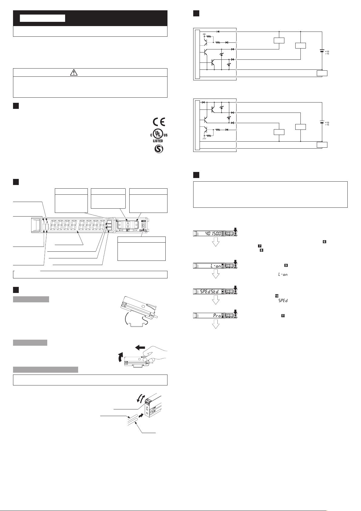
PART DESCRIPTION
Sensing output 2
selection indicator
(Yellow)
Sensing output 1
selection indicator
(Yellow)
Sensing output 1
operation indicator
(Orange)
Sensing output 2
operation indicator
(Orange)
<Reference>
Pressing down SET key + MODE key for 3 sec : Set key lock or Release key lock
3
MOUNTING
How to connect
1. Fit the rear part of the mounting sec-
tion of the amplier on a DIN rail.
2. Press down the rear part of the
mounting section of the unit on the
DIN rail and fit the front part of the
mounting section to the DIN rail.
UP key
• Teaching
• Threshold value
ne adjustment
• Select setting items
Digital display
(Green / Red)
MODE indicator: L / D (Yellow)
MODE indicator: CUST (Yellow)
MODE indicator: PRO (Yellow)
SET key
• Teaching
• Confirm setting
contents
MODE key
• Select Modes
• Cancel during setting
• Select sensing output 1/2
by pressing long
2. Press down
35mm width DIN rail
DOWN key
• Teaching
• Threshold value ne
adjustment
• Select setting items
1. Fit
4
I/O CIRCUIT DIAGRAMS
<FX-505-C2>
(Brown) +V
Load
Load
+
12 to 24V DC
%
-
Load (0 to 250Ω)
Main circuit
(Pink) External input
(Black) Sensing output 1
(White) Sensing output 2
(Blue) 0V
(Gray) Monitor current output (4 to 20mA)
<FX-505P-C2>
(Brown) +V
(Black) Sensing output 1
+
(White) Sensing output 2
Main circuit
Note: Make sure to insulate the ends of the unused lead wires.
5
OPERATION PROCEDURE
(Pink) External input
(Blue) 0V
(Gray) Monitor current output (4 to 20mA)
Load
Load
12 to 24V DC
%
-
Load (0 to 250Ω)
● The sensing output can be switched to sensing output 1 or sensing output 2
by holding down the mode key.
● The changed settings are not stored if turning the power OFF while setting.
Therefore, conrm the settings by pressing the SET key before turning the
power OFF.
● When turning ON the power, RUN mode is displayed and the digital display
shows the threshold value (green) and the incident light intensity (red).
<RUN mode>
<Sensing output operation mode>
<CUSTOM mode>
<PRO mode>
<RUN mode>
• Displays threshold value (green) and incident light intensity (red).
• Teaching, threshold value ne adjustment and key lock function
can be set.
• For setting method of each function, refer to “
MODE,” “
TION,” or “
• Select either Light-ON or Dark-ON.
• For the setting, refer to
MODE
• The default setting is “ ” (Light-ON).
• An item set in CUSTOM mode (Response time setting, Emission
power setting and Hysteresis setting) is displayed.
• For details, refer to “
• The default setting is “
• Advanced setting can be done.
• For the setting, refer to “
THRESHOLD VALUE FINE ADJUSTMENT FUNC-
KEY LOCK FUNCTION.”
.”
“ SENSING OUTPUT OPERATION
CUSTOM MODE.”
” (response time setting).
PRO MODE.”
TEACHING
How to remove
1.
Push the controller forward.
2. Lift up
1. Push forward
2. Lift up the front part of the amplier
to remove it.
How to connect the ber cable
Be sure to t the attachment to the bers rst before inserting the bers to the
amplier. For details, refer to the Instruction Manual enclosed with the bers.
1. Snap the fiber lock lever down till it
stops completely.
2. Insert the ber cables slowly into the
inlets until they stops. (Note)
3. Return the fiber lock lever to the
original position till it stops.
Note: With the coaxial reective type ber, such as , FD-G4 or FD-FM2, insert the single core ber cable into the
beam-emitting inlet “P” and the multi-core ber cable into the beam-receiving inlet.
If they are inserted in reverse, the sensing performance will deteriorate.
Fiber for emitter
1. Snap
Fiber lock lever
3. Return
2. Insert
Fiber for
receiver
Page 2
6
<PRO1>
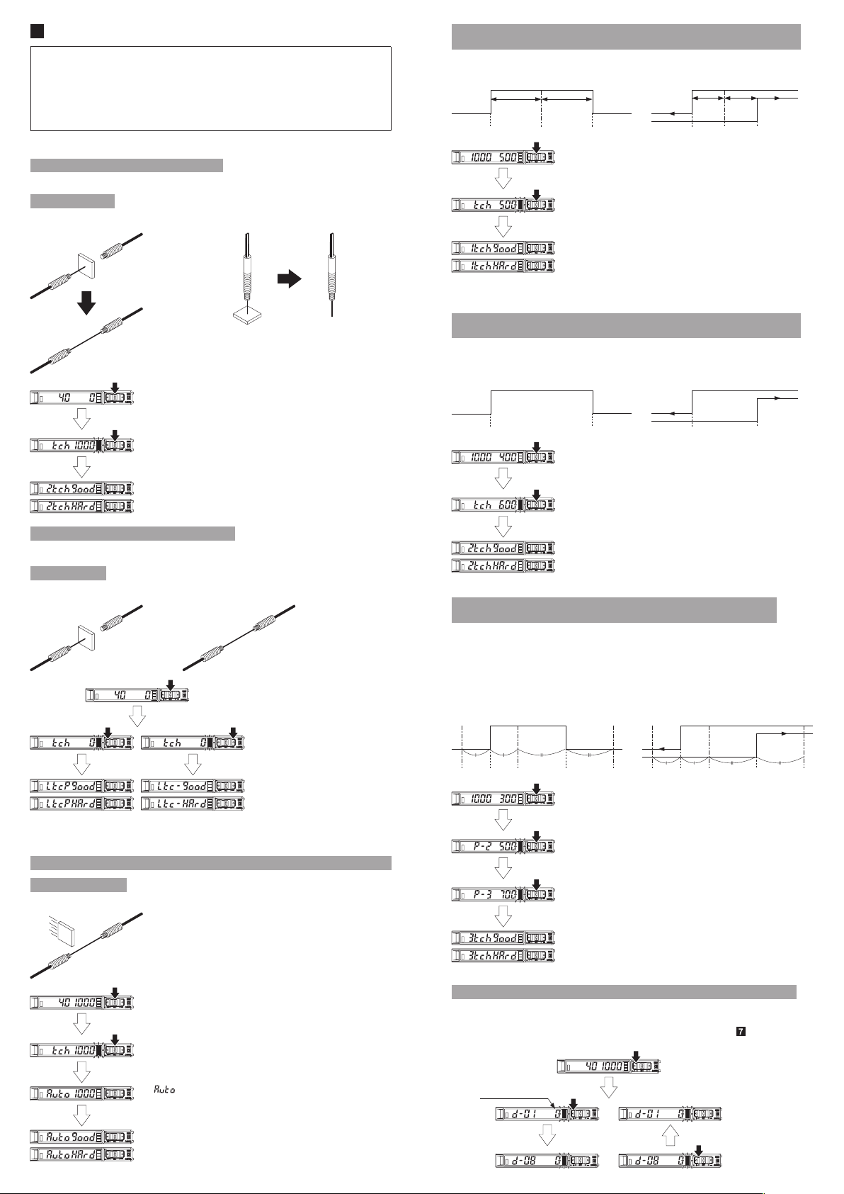
TEACHING MODE
● Be sure that detection may become unstable depending on the use environ-
ment in teaching if less margin is applied.
● When teaching in Window comparator mode or Hysteresis mode, a setting
has to be made in PRO mode beforehand.
In case 1-point teaching, make sure to set the shift amount. (initial value is
10% or 100)
For the setting, refer to “PRO MODE OPERATION MANUAL.”
● Teaching can be set in RUN mode.
Useful when sensing object can be set
● This is basic teaching method.
2-point teaching
<Thru-beam type>
1
2
1. Press the SET key in the sensing object present condition.
<Reective type>
1 2
1-point teaching
[Window comparator mode (except sensing output 2) / Hysteresis mode]
● This is method to set the shift amount to the desired value and to set the
threshold range by using the 1-point teaching.
<Window comparator mode>
Set to desired value
1_SL P-1 2_SL
Notes 1)
The shift amount of 10% is an initial value. The shift amount can be set in PRO mode. Furthermore, the shift
value can be set in incident light amount. For setting method, refer to “PRO MODE OPERATION MANUAL.”
2) If the value after setting exceeds the maximum (minimum), the maximum (minimum) sensitivity will be set.
Set to desired value
1. Pressing SET key down
2. Press the SET key down in the sensing object present condition.
3. The threshold value (1_SL) that is 10% lower from the incident
light intensity and the threshold value (2_SL) that is 10% higher
from the incident light intensity are set. (Note 1, 2)
Stable sensing is possible
Stable sensing is not possible
<Hysteresis mode>
Set to desired value
1_SL P-1 2_SL
Set to desired value
2-point teaching
[Window comparator mode (except sensing output 2) / Hysteresis mode]
● This is method to set the threshold range by conducting the 2-point teaching (P-1, P-2).
● When conducting teaching, use sensing objects (P-1 and P-2) whose incident
light intensities are different from each other.
<Window comparator mode>
<Hysteresis mode>
2. Press the SET key in the sensing object absent condition.
Stable sensing is possible
Stable sensing is not possible
Useful when sensing object cannot be set
● This is teaching method in case small object or object in back ground are existing
Limit-teaching
<Thru-beam type and refractive type are common>
or
1. Press the SET key in the sensing
object present condition or non
sensing object present condition.
2. The threshold level is shifted to
high value (low sensitivity) by
pressing down UP key.
The threshold level is shifted to low
value (high sensitivity) by pressing
down UP key.
Stable sensing is possible
Stable sensing is not possible
Note: The shift value of approx. 15% is an initial value. Display of the shift value can be change in percentage
[approx. 0 to 999% (unit 1 %)] or incident light intensity [0 to 9999 (unit 1)].
For setting the shift amount, refer to “PRO MODE OPERATION MANUAL.”
Useful when not want to stop production line and to keep the sensing object move
Full-auto teaching
<Thru-beam type and refractive type are common>
1_SL (P-1) 2_SL (P-2)
1. Pressing SET key down (1st time)
2. Press down the SET key in the sensing object present condition.
(2nd time)
Stable sensing is possible
Stable sensing is not possible
Note: If the value after setting exceeds the maximum (minimum), the maximum (minimum) sensitivity will be set.
1_SL (P-1) 2_SL (P-2)
3-point teaching
[Window comparator mode (except sensing output 2) / Hysteresis mode]
● This is the method to conduct the 3-point teaching (P-1, P-2, P-3) and to set the
threshold range by setting the threshold value (1_SL) of the mid-point between “A”
and “B” and the threshold value (2_SL) of the mid-point between “B” and “C”.
● When conducting teaching, use sensing objects (A, B and C) whose incident
light intensities are different.
● After teaching, P-1, P-2 and P-3 will be automatically relocated in ascending order:
i.e. the lowest value is placed in “A”, the second lowest in “B” and the highest in “C”.
<Window comparator mode>
A 2_SL1_SL B C
1. Press SET key down in the sensing object present condition (1st time)
2.
Press SET key down in the sensing object present condition (2nd time)
3.
Press SET key down in the sensing object present condition (3rd time)
<Hysteresis mode>
A 2_SL1_SL B C
1. Pressing SET key down
Pressing down long
Run the sensing object on the line and hold down the SET key.
2.
3. “ ” is displayed on the digital display (green) and when the
sensing object passed through, release the SET key.
Automatic
Stable sensing is possible
Stable sensing is not possible
Stable sensing is possible
Note: If the value after setting exceeds the maximum (minimum), the maximum (minimum) sensitivity will be set.
Stable sensing is not possible
Span adjustment in rising differential mode or trailing differential mode
● Press the SET key to conrm the setting item.
● The threshold can be set by using the threshold value ne adjustment function.
For the threshold value ne adjustment function, refer to “
THRESHOLD
VALUE FINE ADJUSTMENT FUNCTION”
Changed intensity
Short span
Long span
Page 3
<PRO1>
7
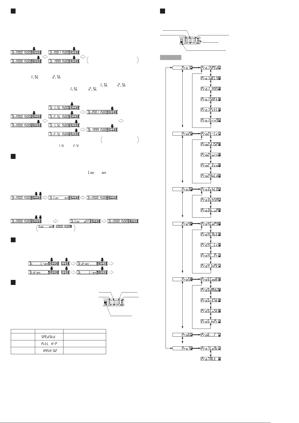
THRESHOLD VALUE FINE ADJUSTMENT FUNCTION
● Set ne adjustment of threshold value in RUN mode.
● Also, the threshold value ne adjustment function can be used in forced ON
output mode and forced OFF output mode
● For setting of the sensing output, refer to “PRO MODE OPERATION MANUAL.”
<Normal mode, Rising differential mode or Trailing differential mode>
Press down
UP / DOWN key
Press down
SET key
Conrmed
Automatically set without pressing
down SET key in approx. 2 sec.
<Window comparator mode or Hysteresis mode>
● When setting sensing output to the window comparator mode or hysteresis
mode, “
SET key for 2 sec.
In case conducting threshold value ne adjustment of “ ” or “ ”, press
down UP key or Down key, and “
threshold value ne adjustment can be conducted.
Press down
UP / DOWN key
Note: It may not respond when values of “ ” and “ ” are close because of relation of hysteresis. Be sure
to conrm with this device.
8
KEY LOCK FUNCTION
” and “ ” can be changed to another by pressing down
” or “ ” are displayed. Then, the
Press down
UP / DOWN key
Press down
SET key
Automatically set without
pressing down SET key.
Conrmed
● The key lock function prevents key operations so that the conditions set in
each setting mode are not inadvertently changed.
● If operating key switch after key lock is set, “
digital display.
” is indicated on the
<Set key lock>
Press down for
3 sec. or more
Automatic
<Release key lock>
Press down for
3 sec. or more
are displayed
9
SENSING OUTPUT OPERATION MODE
,
Automatic
● When MODE indicator: L / D (yellow) lights up, sensing output operation can be set.
Press down
UP / DOWN key
10
CUSTOM MODE
● When MODE indicator: CUST (yellow) lights up,
Response time setting, Emission power setting
or Hysteresis setting can be displayed.
Press down
SET key
Conrmed
Conrmed
SET key DOWN key
UP key
MODE key
For the setting procedure, refer to “PRO MODE
OPERATION MANUAL.”
● By pressing UP key or DOWN key, the setting in
each item will be changed.
● Press SET key to conrm the setting.
● For setting of each item, refer to the following
MODE indicator
CUST (Yellow)
table.
Item Digital display Reference item
Response time
setting
Emission power
setting
Hysteresis
setting
<PRO 1: Response time setting>
<PRO 1: Emission power setting>
<PRO 1: Hysteresis setting>
11
PRO MODE
● When MODE indicator: PRO (yellow) lights up, PRO mode can be set.
● For detail of PRO mode, refer to “ PRO MODE OPERATION MANUAL.”
SET key (conrm)
UP (+) key (select)
DOWN (-) key (select)
MODE key
MODE indicator PRO (Yellow)
Procedure
SET
+,
-
+,
-
<PRO2>
<PRO3>
+,
-
<PRO4>
<PRO5>
<PRO6>
<PRO7>
SET
+,
-
+,
-
SET
+,
-
+,
-
SET
+,
-
+,
-
SET
+,
-
+,
-
SET
+,
-
SET
Responce time setting
+,
-
Timer setting
+,
-
Hysteresis setting
+,
-
Shift amount setting
+,
-
Emission power setting
+,
-
Timer range setting
Teaching lock setting
+,
-
Setting items in digital display setting
+,
-
Setting of digital display turning
+,
-
ECO setting
+,
-
Time period hold setting
Data bank loading setting
+,
-
Data bank saving setting
+,
-
Back up setting
Copy setting
+,
-
Copy action setting
+,
-
Copy lock setting
+,
-
Communication protocol setting
+,
-
External input setting
Code setting
+,
-
Display adjustment setting
+,
-
Reset setting
+,
-
CUSTOM setting
+,
-
Interference prevention setting
Sensing output setting
Logic operation setting
+,
-
Setting of threshold value tracking
Page 4
12
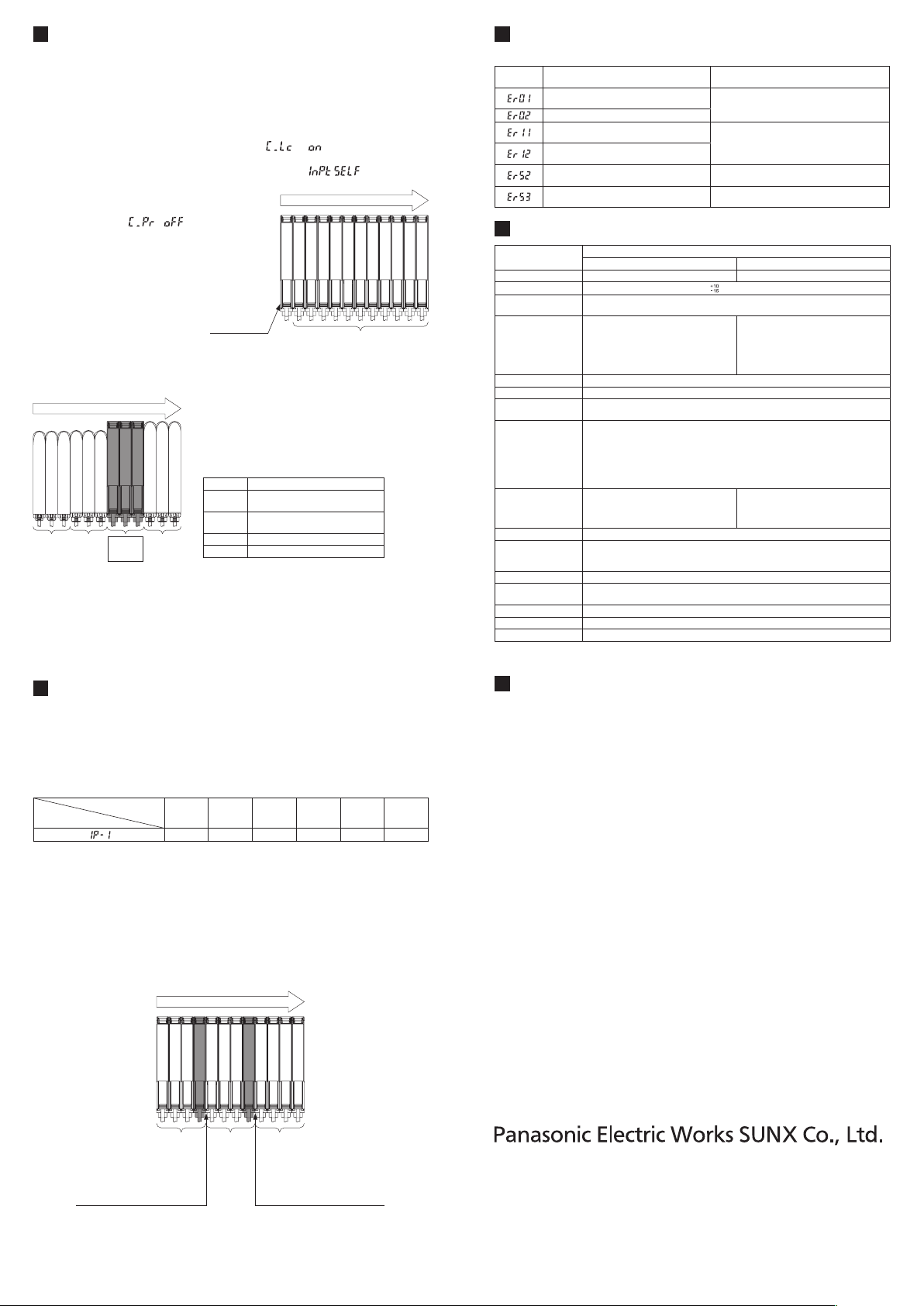
OPTICAL COMMUNICATION
● When the setting of data bank loading / saving, copy setting, or copy action
setting is conducted via optical communications, cascade the sub ampliers
right side to the main amplier as follows.
However, in case using data bank loading / saving, use FX-502□ or FX-505□-C2
as main amplier.
● If an amplier is under any of the following conditions, the setting of data bank
loading / saving, or copy setting cannot be carried out.
• Copy lock setting is set to copy lock ON “
• Digital display is blinking
• External input setting of main amplier is set to
bank loading / saving)
● When communication protocol of a
sub amplier is set to communication
emission halt “
” the set-
.”
” (Only data-
“
Communication direction
.
ting of data bank loading / saving, or
copy setting cannot be carried out to
sub ampliers subsequent to the mentioned amplier.
● Make sure to mount closely like fol-
lows since interference prevention
function is conducted by optical communication.
Main amplier
Sub ampliers
● When this product and other products (e.g. ber sensor ampliers, pressure
sensor controllers, etc.) are connected together in cascade, install those products so that they are in order of Group A, B, D and C as shown in the right gure. This product is included in Group D.
Communication direction
Group Model No.
FX-301□ (Conventional version unit)
A
FX-301B□/G□/H□, LS-401□
FX-301□ (Modied version unit)
B
FX-305□, FX-301□-C1
GroupAGroupBGroupDGroup
C
C LS-403□, DPS series
D FX-500 series
● As for the products that are located between different groups, afx the ampli-
er protection seal FX-MB1 (optional) on the communication window of each
corresponding product.
● Within each group, identical models should be connected in a lump.
● In case conducting copy setting of this device and other FX-500 series togeth-
er, functions which are incorporated in this device will be copied but functions
which are not incorporated in this device will not be copied.
14
ERROR INDICATION
● In case of errors, attempt the following measures.
Error
indication
EEPROM is broken or reached the end of its
working life.
EEPROM writing error
Load of the sensing output 1 is short-circuited
causing an over-current to ow.
Load of the sensing output 2 is short-circuited
causing an over-current to ow.
Communication error when the ampliers are
mounted in cascade.
Communication error between the upper com-
munication unit and ampliers.
15
SPECIFICATIONS
Type
Model No. FX-505-C2 FX-505P-C2
Supply voltage 12 to 24V DC
Power consumption
(Note 1)
Sensing output
(Sensing output 1 / 2)
Output operation Switchable either Light-ON or Dark-ON
Short-circuit protection Incorporated
Response time
Monitor current output
External input
Protection IP40 (IEC)
Ambient temperature
Ambient humidity 35 to 85% RH, Storage: 35 to 85% RH
Material
Cable 0.2mm
Weight (Main body only)
Accessory FX-MB1 (Amplier protection seal): 1 set.
Note: 1) Excluding power consumption of the monitor current output
2) If the display adjustment was conducted, it is not in this range.
Description Remedy
Please contact our ofce.
Turn OFF the power and check the load.
Verify that there is no loose or clearance between
ampliers.
Verify that there is no loose or clearance between
the upper communication unit and ampliers.
NPN output PNP output
Normal operation: 960mW or less (current consumption 40mA or less at 24V supply voltage)
Eco mode: 680mW or less (current consumption 28mA or less at 24V supply voltage)
NPN open-collector transistor
• Maximum sink current: 50mA
• Applied voltage: 30V DC or less
(Between sensing output and 0V)
• Residual voltage: 2V or less
H-SP: 25μs or less, FAST: 60μs or less, STD: 250μs or less, LONG: 2ms or less,
U-LG: 4ms or less, HYPR: 24ms or less, Selectable
• Output current: approx. 4 to 20mA
• Response time: 2ms or less
• Zero-point: Within 4mA ±1%F.S.
• Span: Within 16mA ±5%F.S.
• Linearity: Within ±3%F.S.
• load resistance: 0 to 250Ω
• Signal condition
High: +8V to +V DC or Open
Low: 0 to +1.2V DC (at 0.5mA source current)
• Input impedance: Approx. 10kΩ
-10 to +55°C (If 4 to 7 units are mounted adjacently in cascade: -10 to +50°C or if 8 to 12 units
are mounted adjacently in cascade: -10 to +45°C) (No dew condensation or icing allowed)
Storage: -20 to +70°C
(At 50mA sink current)
[Display in H-SP, FAST, STD: 0 to 4,000, Display in LONG: 0 to 8,000 (Note 2)
Enclosure: Polycarbonate, Protective cover: Polycarbonate
Switch: TPEE,
Cable type
% Ripple P-P10% or less
PNP open-collector transistor
• Maximum source current: 50mA
• Applied voltage: 30V DC or less
(Between sensing output and +V
• Residual voltage: 2V or less
• Signal condition
High: +4V to +V DC (at 3mA sink current)
Low: 0 to +0.6V DC or Open
• Input impedance: Approx. 10kΩ
2
6-core cabtyre cable, 2m long
Approx. 60g
(At 50mA
source
)
current)
]
13
INTERFERENCE PREVENTION FUNCTION
● This device incorporates an interference prevention function by setting different emitting frequencies different from an interference prevention function by
optical communication.
● For Interference prevention function setting procedure, refer to “PRO MODE
OPERATION MANUAL.”
● Possible number of ampliers for interference prevention function is different
as shown in table below.
Interference
prevention function setting
Response time
H-SP FAST STD LONG U-LG HYPR
0 2 4 8 8 12
● In case putting in more ampliers than limit of interference prevention func-
tion, put the amplier protection seal to amplier which is adjacent of end of
an amplier that the interference function is valid or set OFF in communication
protocol setting of the end of amplier that the interference prevention function
is valid.
Example: Putting in 12 of this device and set STD of response time setting.
• Possible number of interference prevention is 4.
Put the amplier protection seals 4th and 5th ampliers and between 8th
and 9th ampliers or change the communication protocol setting of 4th and
8th to OFF since interference prevention works from 1st to 4th, from 5th to
8th and 9th to 12th.
Communication direction
Interference prevention
possible range
Put a protection seal between
4th and 5th amplier.
Or set communication protocol
setting in 4th to OFF.
Interference
prevention
possible
range
Interference prevention
possible range
Put a protection seal between
8th and 9th amplier.
Or set communication protocol
setting in 8th to OFF.
● In case mounting more ampliers whose response time setting are different,
put protection seal between ampliers that have different response time setting
or set communication protocol setting of the upper amplier to OFF.
● For communication protocol setting procedure, refer to “PRO MODE OPERA-
TION MANUAL.”
16
CAUTIONS
● This product has been developed / produced for industrial use only.
● Make sure that the power supply is OFF while adding or removing the ampliers.
● Take care that if a voltage exceeding the rated range is applied, or if an AC
power supply is directly connected, the product may get burnt or be damaged.
● Take care that short-circuit of the load or wrong wiring may burn or damage the product.
● Do not run the wires together with high-voltage lines or power lines, or put
them in the same raceway. This can cause malfunction due to induction.
● The specication may not be satised in a strong magnetic eld.
● Verify that the supply voltage variation is within the rating.
● If power is supplied from a commercial switching regulator, ensure that the frame
ground (F.G.) terminal of the power supply is connected to an actual ground.
● In case noise generating equipment (switching regulator, inverter motor, etc.)
is used in the vicinity of this product, connect the frame ground (F.G.) terminal
of the equipment to an actual ground.
● The ultra long distance (U-LG, HYPR) mode is more likely to be affected by
extraneous noise since the sensitivity of that is higher than the other modes.
Make sure to check the environment before use.
● Do not use during the initial transient time (H-SP, FAST, STD: 0.5 sec., LONG,
U-LG, HYPR: 1 sec.) after the power supply is switched ON.
● Use same power supply when mounting adjacently.
● Extension up to total 100m is possible. When you extend the cable, be sure the power sup-
ply voltage is 12V DC or more and use cables which have 0.3mm
cross-section area. However, in order to reduce noise, make the wiring as short as possible.
● Make sure that stress by forcible bend or pulling is not applied to the sensor
cable joint and ber cable.
2
or more of conductor
● This product is suitable for indoor use only.
● Avoid dust, dirt, and steam.
● Take care that the product does not come in contact with oil, grease, organic
solvents such as thinner, etc., strong acid or alkaline.
● This product cannot be used in an environment containing inammable or ex-
plosive gasses.
● Never disassemble or modify the product.
● This product adopts EEPROM. Settings cannot be done 100 thousand times
or more because of the EEPROM’s lifetime.
http://panasonic-electric-works.net/sunx
Overseas Sales Division (Head Ofce)
2431-1 Ushiyama-cho, Kasugai-shi, Aichi, 486-0901, Japan
Phone: +81-568-33-7861 FAX: +81-568-33-8591
Europe Headquarter: Panasonic Electric Works Europe AG
Rudolf-Diesel-Ring 2, D-83607 Holzkirchen, Germany
Phone: +49-8024-648-0
US Headquarter: Panasonic Electric Works Corporation of America
629 Central Avenue New Providence, New Jersey 07974 USA
Phone: +1-908-464-3550
PRINTED IN CHINA © Panasonic Electric Works SUNX Co., Ltd. 2010
 Loading...