

Panasonic ER-X, ER-X008, ER-X032, ER-X048, ER-X064 Instruction Manual
...
INSTRUCTION MANUAL
Area ionizer ER-X series
CME-ERX No.0060-02V
Thank you for purchasing Panasonic products.
Read this Instruction Manual carefully and thoroughly for the correct and optimum use of
this product.
Kindly keep this manual in a convenient place for quick reference.
WARNING
Never use this product as device for personnel protection.
●
In case of using devices for personnel protection, use products which meet laws or
●
standards, such as OSHA, ANSI or IEC etc., for personnel protection applicable in
each region or country.
1 FOR SAFETY USE
WARNING
This product produces high voltages.
●
Do not use this product in places where there may be a danger of flammable or
●
combustible items being present.
To prevent electric shock and to conduct proper discharge, be sure to ground a frame
●
ground (F.G.) terminal of a controller.
Do not place hands near the discharge needle. Doing so may cause electric shock.
●
Since the tip of the discharge needle is sharp, take sufficient care in handling the
●
discharge needle, or injuries may result.
The high-voltage cable between the head and the high-voltage unit must be xed and
●
the minimum bend radius is R30 mm or more.
In case of using at the bend radius R30 mm or less and using at moving part may
cause re and break down, etc. of the high-voltage cable.
Clean the discharge needle regularly (about once a week). Otherwise, optimum charge
●
removal performance may not be achieved, and accidents or operating problems may occur.
If this product is used in a conned space, ozone emitted from this product may be
●
detrimental. Be sure to provide ventilation.
Do not direct ionized air toward the face. Ozone may cause irritation to places such as
●
the nose and throat.
CAUTION
This product has been developed / produced for industrial use only.
●
Do not use this product for purposes other than electric charge removal.
●
Do not use this product in environments which are outside the specification range,
●
otherwise operating problems or damage may occur. In addition, the operating life of the
product may become signicantly reduced.
This product is a precision device. Do not apply a shock to it by dropping, for example.
●
Accidents or operating problems may occur.
Never disassemble, repair or modify this product. Accidents or operating problems may occur.
●
Do not throw this product in re. It may explode or toxic fumes may be generated.
●
Do not run the wires together with high-voltage lines or power lines or put them in the
●
same raceway.
This can cause malfunction due to induction.
When connecting/removing the head or performing wiring or inspection work, be
●
sure to turn off the power rst. Not doing so may result in accidents, electric shock or
operating problems.
After connecting the cables, check that the connections are correct before turning on the
●
power. If the cables are connected incorrectly, operating problems or accidents may occur.
Verify that the supply voltage variation is within the rating.
●
In case using switching regulator, be sure to connect F.G. terminal.
●
When using as a CSA and UL compliant product, use a CLASS 2 CSA/UL certied
●
power supply, or a CSA/UL certied power supply that has been evaluated as a Limited
Power Source as specied in CAN/CSA-C22.2NO.60950-1/UL60950-1.
Do not use a cable with any damage such as cracks or splitting. Risk of accidents and
●
failure.
Avoid use in a location with signicant steam or dust, or in a location where the product
●
may come in direct contact with water, oil, or welding spatter.
Avoid use at an elevation higher than 2000m, and outdoor use.
●
Do not touch the discharge needle with hard objects such as tools. If the discharge
●
needle becomes broken, it will not provide sufcient charge removal performance, and
moreover operating problems or accidents may occur.
During installation, fasten the product securely. If it is not securely fastened or it is
●
subjected to continuous vibration or shock, accidents or operating problems may result.
Power cable that are 0.15mm2 or more and 30m or less in total length for wiring.
●
Also, keep the wiring as short as possible in order to prevent noise.
When disposing of this product, treat it appropriately as industrial waste.
●
After starting discharge, it takes approximately 30 minutes for charge removal
●
performance to stabilize. Therefore, wait 30 minutes before adjusting ion balance.
Use the correct combination of head, discharge needle unit and controller.
●
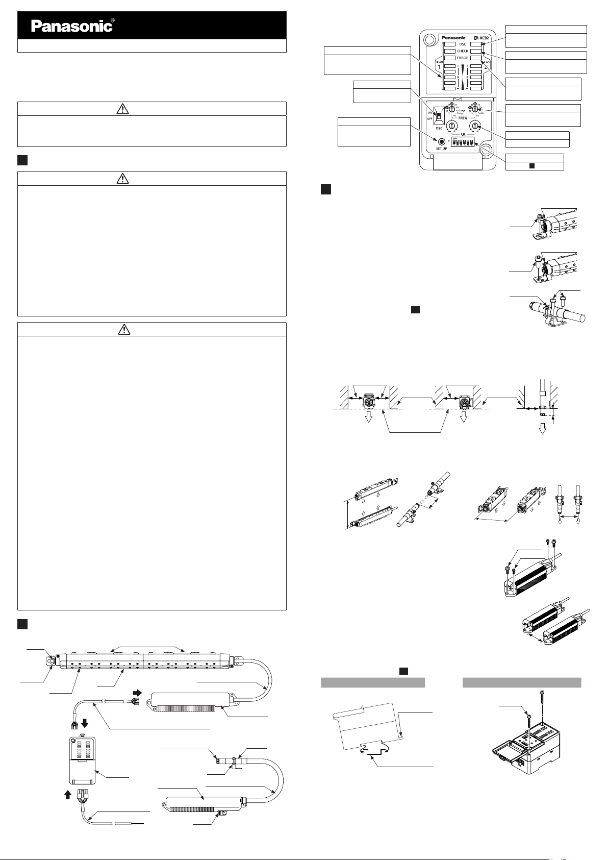
2 PART DESCRIPTION
Discharge needle unit
Air inlet
Head
mounting
bracket
Discharge
needle
Note: The minimum bend radius of the high-voltage cable is R30 mm.
ER-XANT or ER-XANS
Head
ER-X□
Head connection cable
ER-XCCJ2H, ER-XCCJ5H or ER-XCCJ10H
Discharge needle unit
ER-XANT1
Controller
ER-XC02
High-voltage unit
Power cable (optional)
ER-XCC2 or ER-XCC5
High-voltage cable (Note)
High-voltage unit
Bracket
High-voltage cable (Note)
Air inlet
Head
ER-X001
<Controller>
Discharge indicator (green) (Note)
Lights up during discharge , blink-
Level meter indicator (green)
Indicates static buildup around the
head or the amount of ion generated
from the head.
Discharge control switch
ON: Discharge allowed
OFF: Discharge halt
SET UP button
Stores the settings for the
amount of ion and the check
threshold in memory.
Note: An abbreviation of DISCHARGE.
ing during discharge stopped.
CHECK indicator (orange)
Lights up when dirt, wear, etc. of
the discharge needle is detected.
ERROR indicator (red)
Lights up when abnormal
discharge is detected.
Discharge frequency setting switch
Switches between discharge
frequency settings.
Ion balance setting switch
Sets ion balance.
Various setting switch
Refer to “
6 SETTING.”
3 INSTALLATION
<Head installation>
● Using 2 M4 screws or 1 M6 screw, mount the head
onto the equipment housing. In case using this product in where there is vibration, use spring washers
M4 screw
etc. as a countermeasure.
● Loosen the angle adjustment screw, adjust the head
angle, and then fasten the head with the tightening
torque of 0.5 N∙m or less.
● The position of the head mounting bracket of the
ER-X001
M6 screw
should be at least 20 mm from the end of the head. The
tightening torque of the screw for head xation should be
0.5 N•m or less.
Screw for
head xation
● After mounting the head, set the controller according
Surrounding
metal
SETTING
● Side mounting
(10Hz or more)
50mm or more
100mm
or more
” in order to
Surrounding
metal
50mm or more
to the procedures in “6
appropriately remove static electricity.
Notes: 1) Be sure to ground the equipment housing onto which the head is mounted.
2) The distance between the head and the charge removing object should be 30 mm or more.If the static
buildup of the charge removing object is 30 kV or more, set the distance to 50 mm or more.
3) If there is metal near the head or between the head and the charge removing object, ion is absorbed,
hindering appropriate static removal. Install the head based on the above.
4) In case using the side mounting, the discharge frequency should be 10Hz or more.
● Back-side mounting
(All frequencies)
50mm or more
The discharge muzzle
must exceed this line
5) When installing two or more heads in face to face or parallel using different frequency, keep the distance be-
tween the heads 400mm or more.
When installing the heads face to face, install heads in distance that the heads can parform the charge
removal of a side of the object individualy.
100mm
or more
(surrounding metal.)
● Face-to-face installation ● Parallel installation
<High-voltage unit installation>
● Use 2 M4 screws or 2 M6 screws to fasten the
head.
The tightening torques for fastening, are as follows.
When using M4 screws: 1.2N·m
When using M6 screws: 2.5N·m
Notes: 1) Do not place any objects on top of the high-voltage unit.
2) When using multiple heads, keep the distance of at least 10 mm
between the high-voltage units.
3) When fastening the high-voltage unit using M6 screws, fasten
before connecting the head connection cable.
4) Please x the high-voltage unit of
ER-X001
with M6 screw.
10mm or
more
<Controller installation>
● Mount the controller on a 35 mm wide DIN rail or using M4 screws. For mounting
dimensions, refer to “
16 DIMENSIONS
”
When mounting on a DIN rail When mounting using M4 screws
Lock release
lever
1
Pull the lock release lever to remove this
•
product from the DIN rail.
2
35 mm wide DIN rail
•
M4 screw
The tightening torque should be 1.2 N·m or
less.
Angle adjustment
screw
Angle adjustment
screw
● Mouting ER-X001
20mm
or more
M6 screw
M4 screw
M4 screw
20mm
or more
50mm
or more
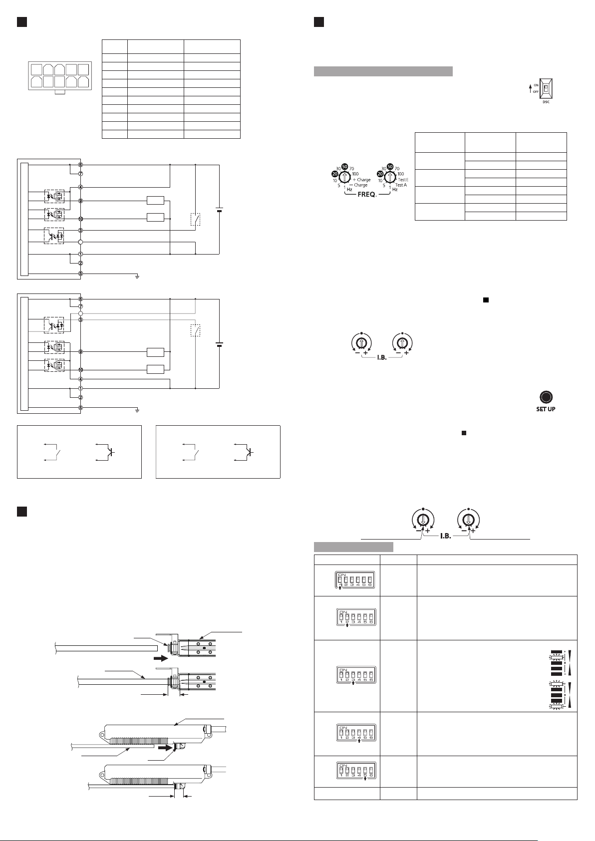
4 WIRING
●Power connector Pin arrangement
1 2 3 4 5
6 7 8
Housing: 5569-10A
[Manufactured by Molex Inc.]
Note: Wire colors are colors of power supply cable of option.
9 10
(Front view)
●When connecting the output to negative common
Main circuit
●When connecting the output to positive common
Main circuit
*1 *2
Non-voltage contact or
PNP transistor/open collector
or
Contact “closed” or transistor ON: Discharge halt
Contact “open” or transistor OFF: Starting discharge
Notes 1) In order to prevent electric shock and perform proper discharge , be sure to ground the F.G. terminal.
In addition, the head of
2) To stop discharge, turn ON the discharge control input for 20 ms or longer. To start discharge, turn OFF (open)
the discharge control input. Discharge will start in 20 ms.
Terminal
No.
1 0V Blue
2 COM(-)
3 Discharge control input Pink
4 COM(OUT) Violet
5 F.G. terminal Green/Yellow
6 24V Brown
7 COM(+)
8 COM(IN) White
9 Alarm output Orange
10 Error output Black
(Brown)+V
COM(+)
(Violet) COM(OUT)
(Orange) Alarm output
(Black) Error output
(Pink) Discharge control input
(White) COM(IN)
8
8
(Blue)0V
-
)
COM(
(Green/Yellow)F.G.
(Brown)+V
COM(+)
8
(White) COM(IN)
(Pink) Discharge control input
(Orange) Alarm output
(Black) Error output
(Violet) COM(OUT)
(Blue)0V
COM(
-
)
(Green/Yellow)F.G.
ER-X001
and the F.G. terminal of a controller are common.
Terminal name Color code
-
-
Load
Load
(Be sure to ground.)
Load
Load
(Be sure to ground.)
Non-voltage contact or
NPN transistor/open collector
+
24V DC
10%
±
-
1
※
2
※
+
24V DC
-
10%
±
or
Contact “closed” or transistor ON: Discharge halt
Contact “open” or transistor OFF: Starting discharge
5 PIPING
● Air supplied to this product will reduce contamination of the discharge needle and
improve the charge removal speed.
● The outer diameter of the air tube to t to the air inlet portion of this product should
be ø6 mm.
● Make sure that clean air (air containing no water, no oil and no dust) should be
supplied.
● Since the pressure will drop when the air piping from the main pressure supply
is extended or pneumatic components (e.g., needle valve, speed controller, mini
lter) are added, keep an eye on the pressure supply to the ionizer making sure
it is not in short supply. For the pneumatic components, select those that can
accommodate the air supply ow rate.
Except ER-X001
<
Piping in the head
ER-X001
<
Piping in the High-voltage unit
Note: After inserting the tube into the joint of this product, always make sure that the tube is all the way in and securely
inserted.
Insufcient tube insertion will cause air leakage.
>
Air inlet
ø6 mm tube
(11.4mm)
Head section
>
High-voltage unit
6mm air tube
φ
Air inlet
11.6mm
(
)
6
SETTING
● The amount of ion generation is set to enable appropriate charge removal.
● After mounting the head, follow the procedures below to congure the setting.
● When air is used, congure the setting while supplying air.
● Start the setting after 30 minuets of the discharge starting.
How to set the amount of ion generation
1.
Turn the discharge control switch ON and the discharge
Discharge control switch
control input “open” to start discharge.
Make sure that the discharge indicator (green) lights up.
2.
Depending on the installation distance, set the frequency using the discharge
frequency setting switch.
●Guideline when air is not supplied
Discharge frequency
setting switch
For head 1 For head 2
Discharge would be stopped at “Test A”
and “Test E” of Head 2.
Installation distance
30~50mm
50~200mm
200~500mm
500~1,000mm
Discharge
frequency setting
switch
100 100Hz
70 70Hz
50 50Hz
30 30Hz
20 20Hz
10 10Hz
5 5Hz
1 1Hz
Frequency
● When air is supplied,
Set the frequency higher than when air is not supplied. Try 50 Hz (factory default
setting) first to see if it removes static electricity. Since using air, discharge
distance from the object can be longer.
● If the amount of static build up on the charge removing object is large,
Set the frequency lower or make the installation distance shorter.
● In case the voltage resistance of the object is low,
Set the frequency higher or make the installation distance longer.
Note: Depending on the head, different frequencies are accepted. If it is set to a wrong frequency, the discharge stops
and the discharge indicator blinks. For accepted frequencies, refer to "11
3.
After mounting the head, adjust ion balance using the ion balance setting switch.
Note:
4.
Press the SET UP button to lock in the setting. After the
Ion balance setting switch
For head 1 For head 2
Generally, ion reaching the charge removing object is affected by installation environment (nearby metals,
temperature, humidity, etc.). Although this product has been adjusted for ion balance at the factory, the preadjusted
ion balance may differ, depending on the customer’s installation environment. For more appropriate static removal,
please adjust ion balance according to your installation environment.
Turn to “-” to shift ion balance to the “-“ side.
Turn to “+” to shift ion balance to the “+” side.
SPECIFICATIONS
"
SET UP button
setting is completed, level meter indicators change from
blinking to lighting up.
Notes: 1) Conduct the maintenance before setting.
2) Before the setting up, be sure that the check indicator is turned OFF. In case the check the indicator lights up
or blinks, the set up is not started. For detail , reffere to
3) This product works at factory setting before nishing setup (level meter indicator blinks.) And ion balance
control function works at OFF in despite of setting of ion balance control switch. After press down the set up
button and nishing he setting (level meter indicator lights up), starts ion balance control and Check detection
detecting function of ion generation depression )amount based on your enviroment.
(
4)
It takes 30 seconds to 1 minute to complete a setup procedure. Do not change the ambient environment at the
time. In case ambient environment is changed, the set up is not conducted and level meter indicator may blink.
5) In case the discharge frequency setting switch or the ion balance control switch is changed or installed environment is changed, conduct the setup again.
6) The set up is conducted to two heads. Do not wire head that you do not use.
7) Setting the ion balance setting switch shown right, level meter indicators blink. And pushing down the SET
UP button for 3 seconds in this setting, the setting will be the factory setting.
Initializing mode for head 1
9
TROUBLE SHOOTING
“
Initializing mode for head 2
.”
Various setting switch
Various setting switch Name Function
No.1
No.2
No.3
No.4
No.5
No.6 ― Not used.
Notes: 1) All factory default settings are ON.
2) Checking function (detecting function of ion generation depression) is based on amount of ion generation
which was set in the set up.
Check level
changeover
switch
Ion balance
control switch
Indicator
changeover
switch
2 heads
control
switch
Error output
changeover
switch
Switches between ion generation levels to output an alarm.
ON: Lights up the CHECK indicator and outputs an alarm, when ion
generation is reduced to a level that affects static removal.
OFF: Set this if you wish to be alerted soon after ion generation is
reduced.
Switches between automatic ion balance control function settings.
ON: Enables automatic ion balance control function.
Senses the amount of ion generation and automatically controls
it to match the setting of the ion balance setting switch.
OFF: Disables automatic ion balance control function.
Ion continues to generate at the discharge ratio setting of the
ion balance setting switch.
Switches between indications of the level meter indicator (green).
ON: Indicates the static buildup state of immediate
head. It shifts to the “+” or “-” side depending on
the amount of buildup.
(Example) When the charge removing object is
positively charged.
OFF:
Indicates the amount of ion the head generates.
Plus ion generated is indicated on the “+” side
and minus ion on the “-” side.
(Example) When a sufcient amount of plus and
minus ions are generated.
Sets ion generation timing for two heads. If the two heads have
different discharge frequency, this setting will be invalid, and ion will
be generated at the frequency timing of each head.
ON:
When head 1 is generating plus ion, head 2 also generates plus
ion.(synchronous mode)
OFF: When head 1 is generating plus ion, head 2 generates minus ion.
(inversion mode)
Switches between Error output function.
ON:
Outputs an ERROR when ER-X has an error. (such as abnormal
discharging and disconnection of cables )
OFF: Outputs an
ERROR
condition or discharge control input )
at the stop discharging. (in anomalous
 Loading...