

Page 1

6
Custom Presets
6-1 List of Custom Preset Functions ................................... 140
6-2 Displaying the Tools Mode Screen................................ 147
6-3 Configuring the Machine with Tools Mode .................... 149
6
Page 2
Custom Presets
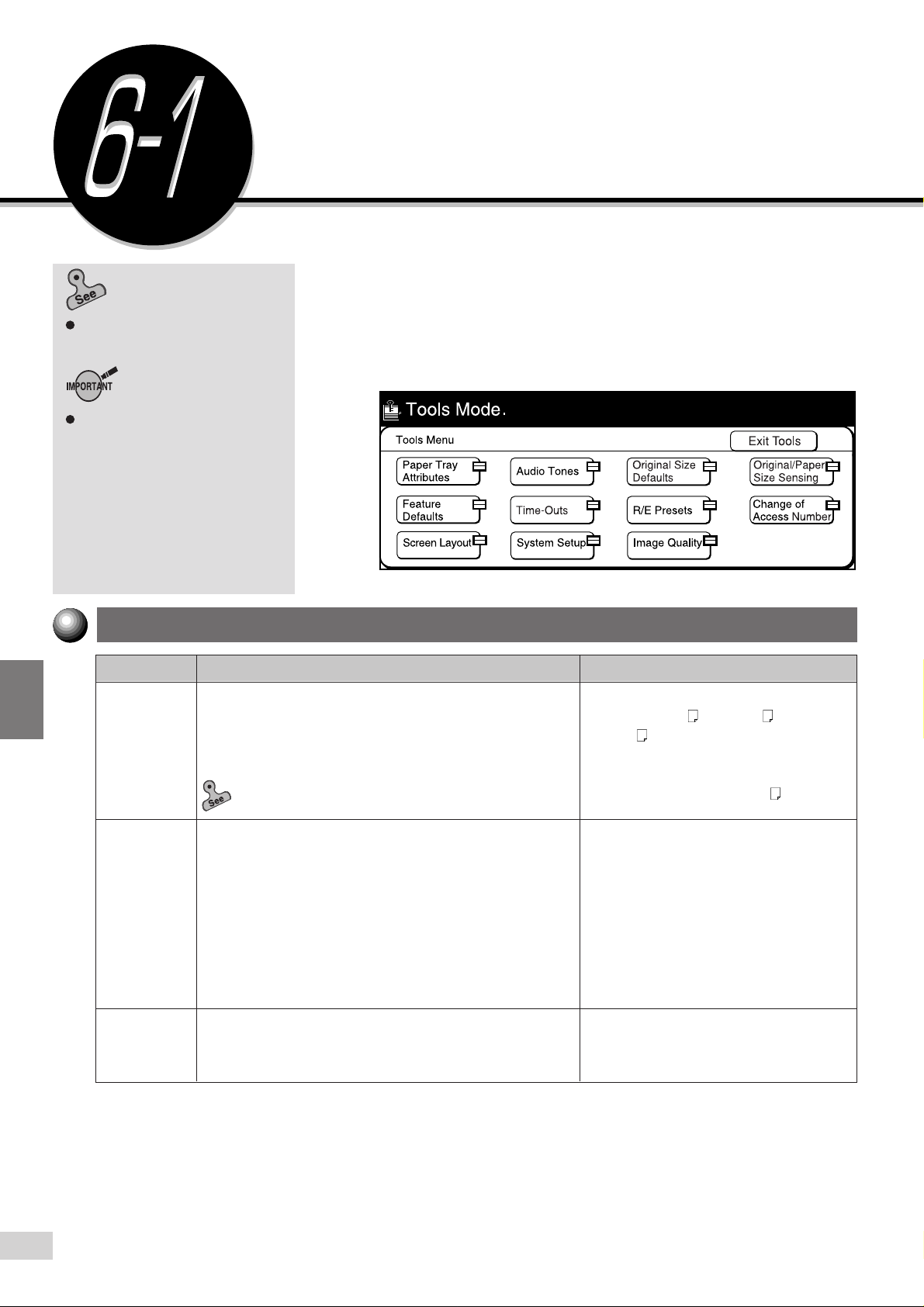
6-2: Displaying the Tools Mode
Screen
on how to display the Tools
Mode screen.
For models with printer feature, items
are divided into Common Settings and
Copy Mode Settings. In Copy Mode
Settings, Feature Defaults, Stored
Jobs, Image Quality, Original Size,
and R/E Presets are displayed. Other
items are shown in Common Settings.
Some settings are different. See the
Operating Instructions (Printer)
details.
for
List of Custom Preset
Functions
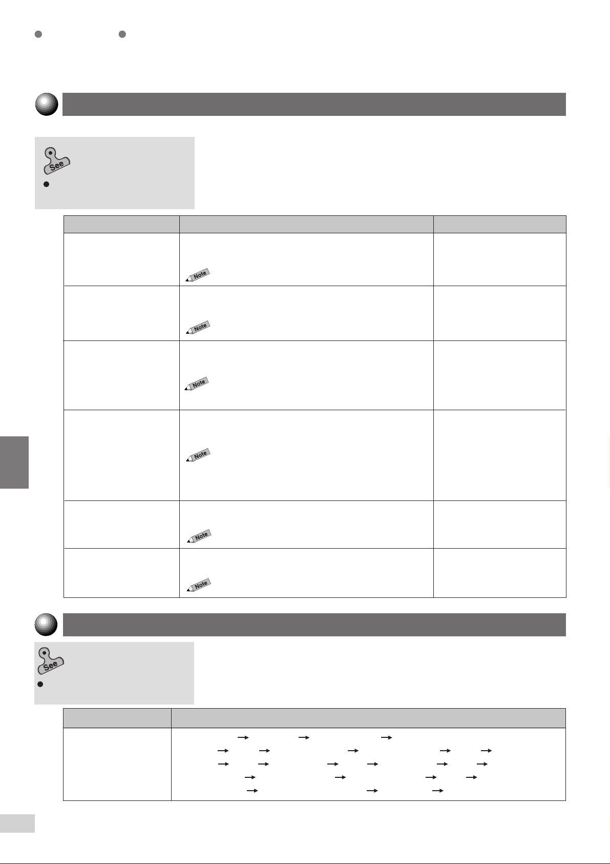
The Settings/Meter Check feature is for the System Administrator to select
the feature defaults as well as customize the features for use.
The System Administrator can select and register these settings by using
Tools Mode. He must enter his Access Number to display this screen. The
factory default is "11111".
6
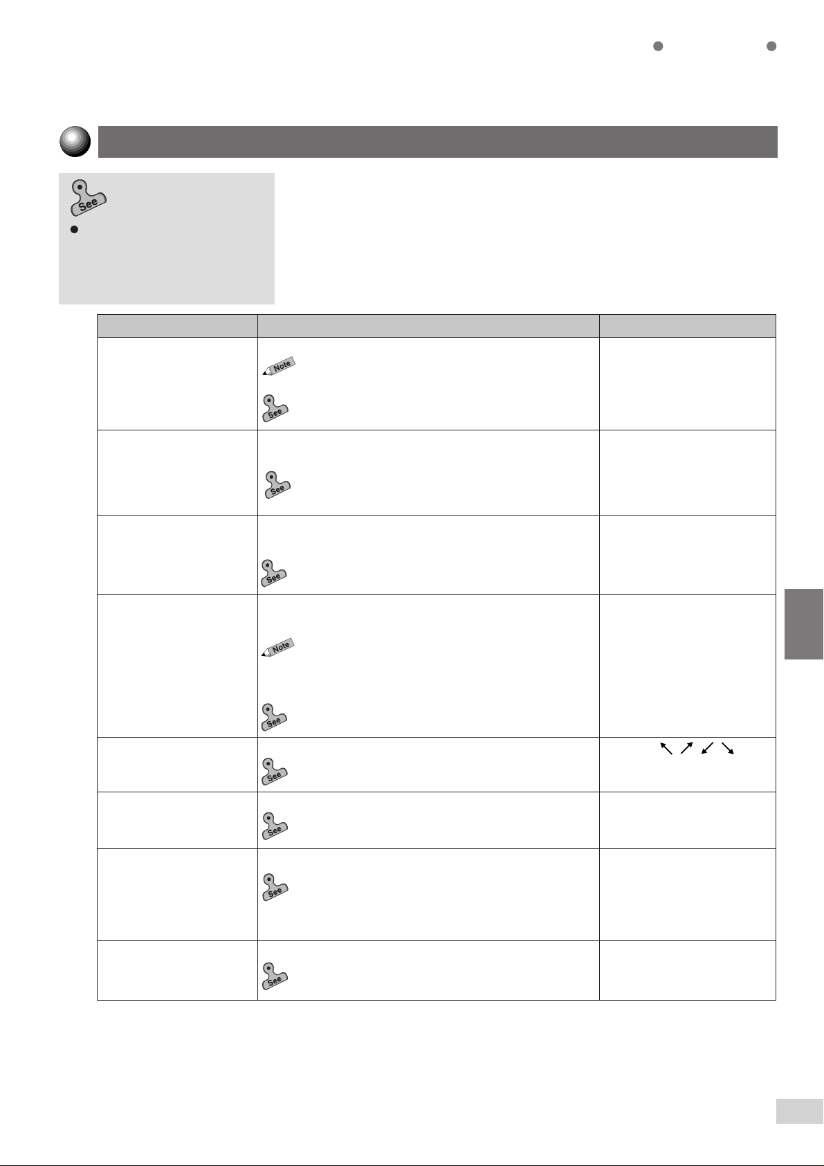
Paper Tray Attributes
Item Description Available Options
Paper Sizes
Trays for APS
(Auto Paper
Selection)/ATS
(Auto Tray
Switching)
Paper Sizes
for APS
(Copy)
Set the paper size of the tray to which you wish to change.
Paper Types:
No Display*, Plain Paper, Transparency, Tracing Paper,
Colored, Noshi Paper, Side 2 Paper, Heavy Weight,
Recycled, Special-1, Special-2, and Special-3.
2-4: Changing the Paper Tray Size
•
APS is a feature which selects the paper tray automatically.
To enable APS for a tray, select Enable. To prevent a tray
from being selected automatically, select Disable. For
convenience, select Disable for trays that will not be used
often (e.g. transparencies and colored paper).
When the selected tray becomes empty during copying, the
A TS feature allows the automatic switching to another tray
with the same-size paper.
Select a paper size amongst those that can be loaded in
Tray 1 as the paper size for APS.
Select Enable if APS is to be used. If not, select Disable.
A/B Series Size
A3 , B4, A4 , A4 , B5 , B5 ,
,
A5
A5
Inch Size
8K (267 x 388 mm), 11 x 17”, 8.5 x 14”,
8.5 x 13”, 8.5 x 11”, 8.5 x 11”
Enable/Disable
Enable*:
Tray 1, 2, 3, 4, 6 (High Capacity Feeder)
Disable*:
Auto Tray Switching:
Always Enable
Enable during APS*
Disable
Enable*/Disable
, 5.5 x 8.5”
6-1 List of Custom Preset Functions
140
* indicates the factory default. Tray 6 (High Capacity Feeder) is optional.
Page 3
Feature Defaults
Select the default values of the features. The settings of the machine will
return to the default values selected here when the power is switched on,
Selecting the feature defaults
Configuring the Machine with Tools
Mode.
Item Description Available Options
Paper Supply Select the default value of Paper Supply.
of
6-3:
when it returns from the power saver mode or when Clear All is pressed.
Although these are the factory defaults, you can make copying more
efficient by customizing frequently used features beforehand as the defaults.
Also, the defaults listed here are reflected in Basic Features, Customized
Features, and Features Menu screens.
You cannot select Auto in Paper Supply if Auto % is
•
already selected in Reduce/Enlarge.
4-2: Selecting a Paper Tray (Paper Supply)
Custom Presets
Auto*, 1, 3, 4, 6 (High
Capacity Feeder)
Transparency Tray In Transparency Separators, select the default value of the
transparency tray.
5-9: Interleaving Blank Sheets between Transparencies
•
(Transparency Separators)
Covers Tray Tray 1, 2, 3, 4, 5 (Bypass)*, 6
Reduce/Enlarge Select the default value for the Reduce/Enlarge feature on
Image Shift (Side 1) Select the default value of Image Shift (Side 1).
Image Shift (Side 2) Select the default value of Image Shift (Side 2).
In Covers, select the default value of the paper tray for
loading the cover stock.
5-18: Inserting Covers (Covers)
•
the Basic Features screen and the Features Menu Screen.
You cannot select Auto % in Reduce/Enlarge if Auto is
•
already selected in Paper Supply.
You can customize the preset ratios for selection. See
•
Presets
of this section for the details.
4-3: Reducing/Enlarging (Reduce/Enlarge)
•
5-7: Setting the Margins (Image Shift)
•
5-7: Setting the Margins (Image Shift)
•
Tray 2, 3, 4, 5 (Bypass)*
(High Capacity Feeder)
100%*, Auto%, 50%,
64%, 78%, 129%, 154%,
200%
R/E
No Shift*, , , , , Auto
Center (Centre)
No Shift,
Mirror Shift*
6
Edge Erase/Copy All Select the default value of Edge Erase/Copy All.
5-8: Erasing the Edges and Copying All
•
(Edge Erase/Copy All)
Image Rotation
Select the default value of Image Rotation.
5-11: Rotating and Copying in Different Directions
•
(Image Rotation)
* indicates the factory default. Tray 6 (High Capacity Feeder) is optional.
Normal (Top & Bottom/Left
& Right 2 mm)*
Variable Erase
Top & Bottom Edges 2-50 mm
Left & Right Edges 2-50 mm
On*, Off
6-1 List of Custom Preset Functions
141
Page 4
Custom Presets
Item Description Available Options
Original Type Select the default value of Original Type.
5-3: Making a Copy according to Original Type (Original
•
Type)
Lighter/Darker
Sharpness
Original Orientation
Output Auto*, Collated, Uncollated
2 Sided 1 -> 1 Sided*, 1 -> 2 Sided,
Select the default value of Lighter/Darker.
You can define the different levels of copy density. See
•
Image Quality
5-2: Adjusting Copy Density (Lighter/Darker)
•
Select the default value of Sharpness.
5-13: Enhancing Sharpness (Sharpness)
•
Select the default value of Original Orientation.
5-10: Selecting the Original Orientation (Original
•
Orientation)
Select the default value for the method of copy output.
4-7: Collating Copy Output (Output)
•
Select default value of 2 Sided.
4-5: Copying on One Side (2-Sided Copy)
•
4-6: Copying on Two Sides (2-Sided Copy)
•
for the details.
Text & Photo*, Text, Photo
Darkest to Normal* to Lightest
(7 levels)
Softer, Soft,
Normal*, Sharp,
Sharper
Head to Top*,
Head to Left
2 -> 2 Sided, 2 -> 1 Sided
6
Booklet Tray
Select tray for paper to be used for booklet creation.
5-20: Creating a Booklet (Booklet Creation)
•
Tray 2-2 , 2-3*, 3, 4
* indicates the factory default.
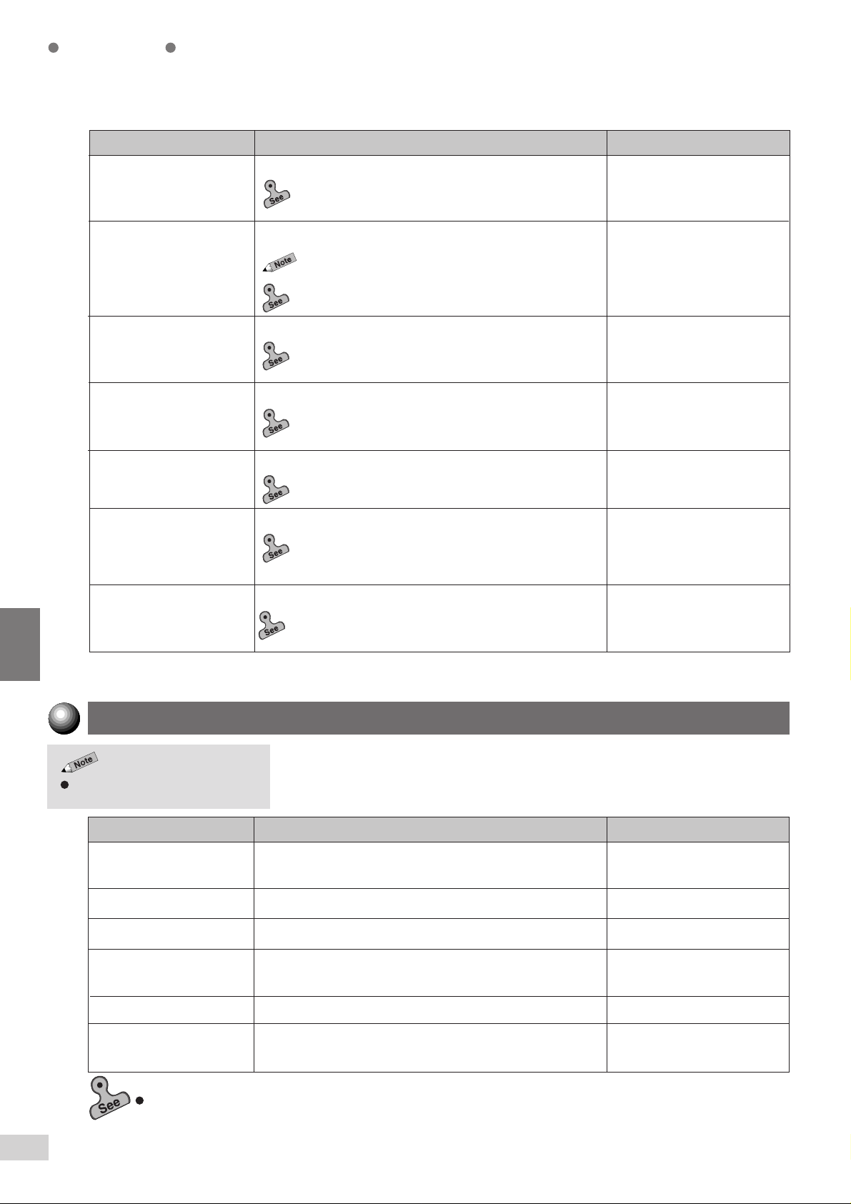
Audio Tones
This section describes the machine tones that you can set to inform you of a
Select Off to disable the tones.
Item Description Available Options
Selection Tone Sound when you have selected a button on the display
Conflict Tone
Machine Ready Tone Off, Soft, Normal*, Loud
completed copy job, machine fault and so forth.
Off, Soft, Normal*. Loud
correctly.
Sound when an error has occurred.
Sound when you press any button on the control panel.Hard Keypad Input Tone Off, On*
After switching on the power, it will sound when the machine
is ready to copy.
Sound when a copy job is completed without error.Copy Job Complete Tone Off, Soft, Normal*, Loud
Off, Soft, Normal*. Loud
Fault T one Off, Soft, Normal*, LoudSound when a fault is detected, for example, the machine
6-2 Displaying the Tools Mode Screen, and 6-3: Configuring the Machine with Tools Mode
6-1 List of Custom Preset Functions
142
has run out of paper, or paper is jammed in the machine.
* indicates the factory default.
Page 5
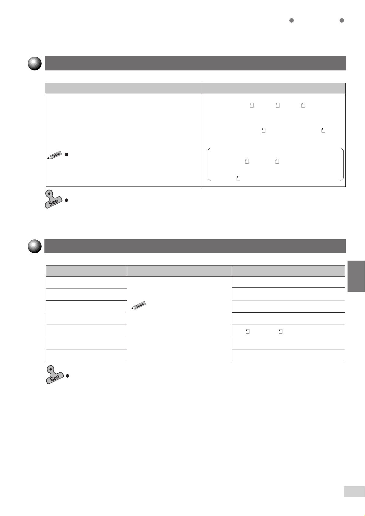
Original Size Defaults
Description Available Options
Select the original size defaults shown in Original Size on the
Customized Features screen or the Features Menu screen.
You can select up to 11 types of original sizes including the
standard sizes (A, B and Inch series original sizes).
To enter a non standard size original, select Original Size and
use the keypad to enter values for the X axis (width) and Y
axis (length).
The size input is shown as Special OOO X OOO mm
6-2: Displaying the Tools Mode Screen, and 6-3: Configuring the Machine with Tools Mode
Custom Presets
A/B Series Size
A3, B4, A4, A4
Inch Size
8K (267 x 388 mm), 11 x 17
8.5 x 11", 8.5 x 11" , 5.5 x 8.5", 5.5 x 8.5"
Input Size
X 1 to 432 mm, Y 1 to 297 mm
Size buttons 1 to 11:
A3*, B4*, B5
11 x 17
"*, 8.5 x 14"*, 8,5 x 11"*,
8.5 x 11
" *
, B5, B5 , A5, A5 , B6, A6
", 8.5 x 14", 8.5 x 13",
*, A4*, A4 *, A5*, A6*,
* indicates the factory default.
Original/Paper Size Sensing
Item
Paper Tray A5*, 5.5 x 8.5"
Document Glass (Size 1) A6*
Document Feeder (Size 1) A5*, 5.5 x 8.5"
Document Feeder (Size 2) A4*, 8.5 x 11"
Document Feeder (Size 3) A4
Document Feeder (Size 4) B4*, 8K (267 x 388 mm)
Document Feeder (Size 5) A3*, 11 x 17"
6-2: Displaying the Tools Mode Screen, and 6-3: Configuring the Machine with Tools Mode
You can switch automatic sensing sizes
for document and paper.
Description
The setting items that are
•
displayed will depend on the
installation of the optional letter/
legal sensor kit, and Tray 6
(High Capacity Feeder) as well
as the model of the
machine.
Available Options
*, 8.5 x 11"
* indicates the factory default.
6
6-1 List of Custom Preset Functions
143
Page 6
Custom Presets
Time-Outs
This setting allows you to set the waiting time until features such as Auto
Clear and Power Saver are enabled. On a model with the printer function,
the timeout settings may differ. See the
6-2: Displaying the Tools Mode Screen, and
6-3: Configuring the Machine with Tools
Item Description Available Options
Copy Job Complete 1 to 59 sec, 1 to 10 min
details.
Enter the time for settings of features to return to their
default values automatically after a copy job is completed.
If this time is longer than one minute, then enter the time
•
in minutes.
Operating Instructions (Printer)
Disable (2 min*)
for
6
Job Program Incomplete 7 to 59 sec, 1 to 10 min
Auto Power Saver Timer 1 to 240 min
Auto Power Off
System Admin Mode Exit
Timer
Auto Resume Enter time for automatically returning to the default screen
Enter the time for the settings of the features to return to
their default values after some settings have been changed.
If this time is longer than one minute, then enter the time
•
in minutes.
Enter time for automatically switching to Power Saver mode
after copying is done or after some settings are made.
Enter the time in minutes.
•
On a model with the printer function installed, power saver
•
mode comes after low power mode and sleep mode.
Enter time for automatically switching off the power after a
copy job is done or after some settings are made.
This feature is available in the case when Auto Power Off
•
in System Setup is set to Enable.
Enter the time in minutes.
•
On a model with the printer function installed, this item is
•
not displayed.
Enter time for automatically returning to the default screen
after settings are made by using the Tools Mode.
Enter the time in minutes.
•
after the settings are made by using the Tools Mode.
If time is longer than a minute, enter the time in minutes.
•
Disable (2 min*)
(15 min*)
15 to 240 min
(60 min*)
10 to 60 min
Disable (10 min*)
Disable (2 min*)
1 to 59 sec, 1 to 10 min
R/E Presets
6-2: Displaying the Tools Mode Screen, and
6-3: Configuring the Machine with Tools Mode
Item Available Options
Presets 1 to 6 25%, 35% A3 A6, 50% A3 A5, 64% 11 x 17" 8.5 x 11",
6-1 List of Custom Preset Functions
144
* indicates the factory default.
You can define the ratios to be displayed as fixed ratios in Reduce/Enlarge.
You can select fixed ratios from 18 types (25-400%) of ratios and place them
in the six preset buttons (1-6).
70%* A3 A4, B4 B5, 78% 8.5 x 14" 8.5 x 11", 81%* B4 A4, B5 A5
86%* A3 B4, A4 B5, 115%* B4 A3 B5 A4, 122%* A4 B4, A5 B5
127% 8.5 x 13" A3, 129% 8.5 x 11" 11 x 17", 141%* A4 A3 B5 B4,
154% 5.5 x 8.5" 8.5 x 14", 180%, 200% A5 A3, 282% A6 A3, 400%
* indicates the factory default.
Page 7
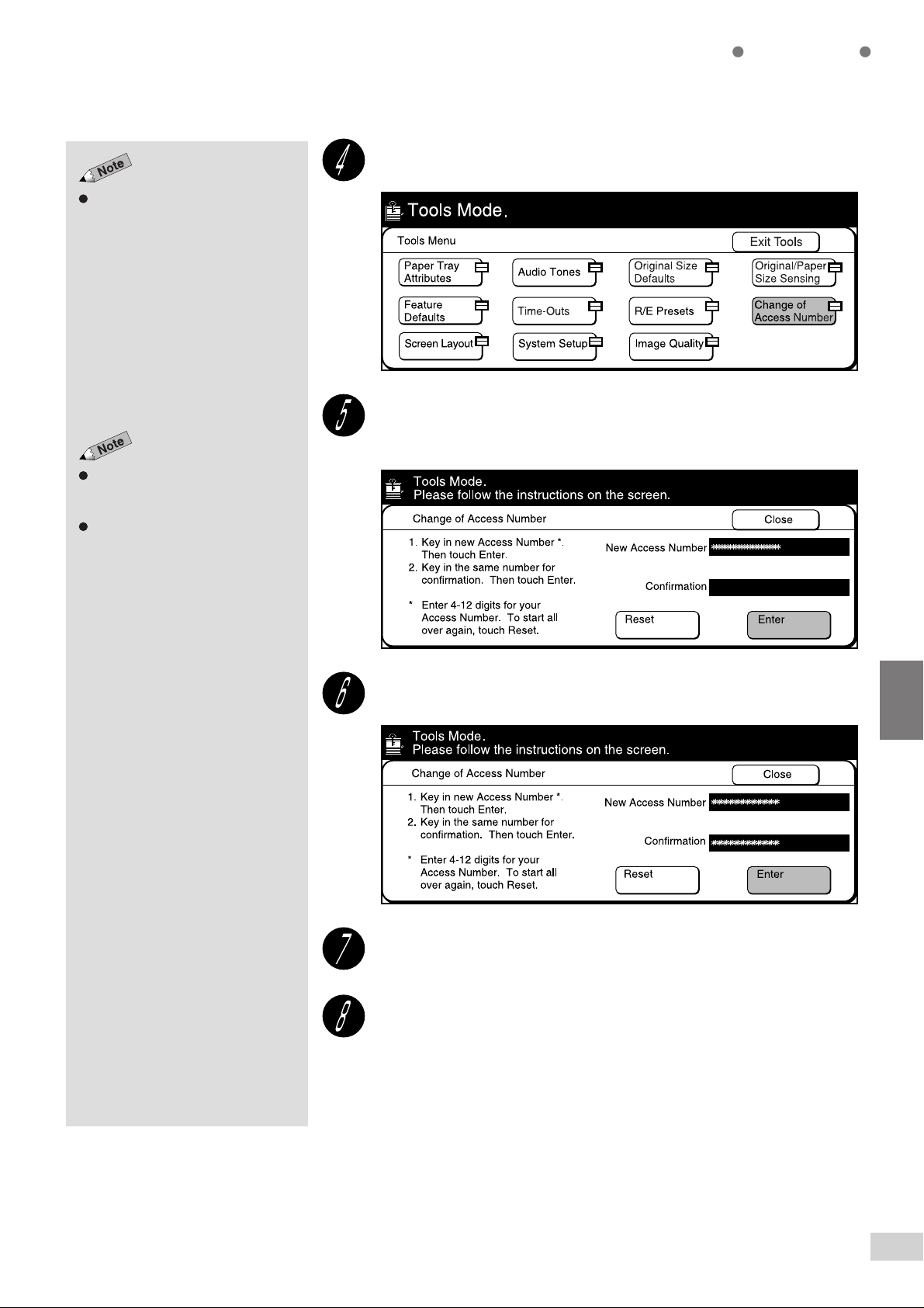
Change of Access Number
You can change the Access Number of the System Administrator. The
Access Number must be in numeric values between 4 to 12 digits. To
The factory default is
“11111”.
Changing the Access Number of the
administrator of 6-3 Configuring the
Machine with T ools Mode
change the Access Number, use the keypad to enter the new access
number twice, and select Enter.
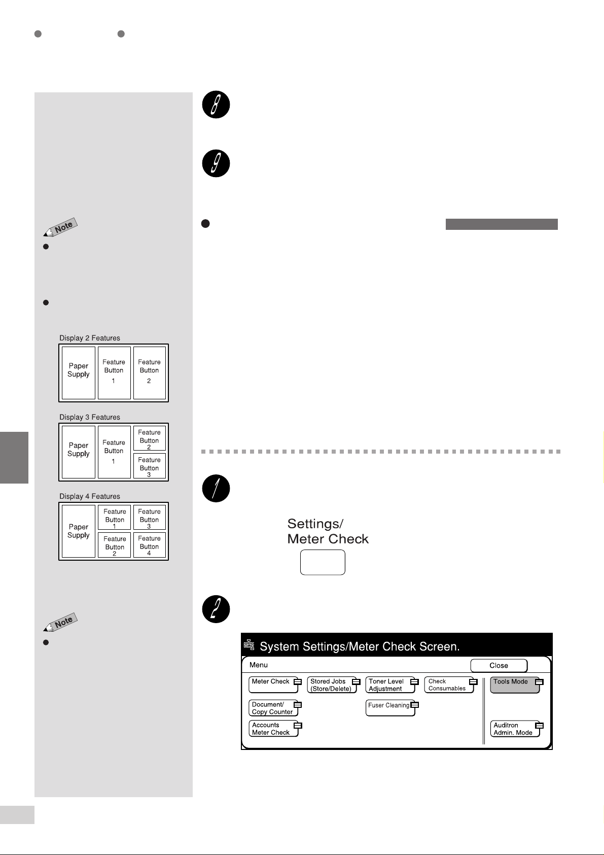
Screen Layout
This feature allows you to customize the default screen, Basic Features
screen, and the Customized Features screen.
Custom Presets
Configuring a screen (default/basic/
customized) of 6-3: Configuring the
Machine with T ools Mode
Item Description Available Options
Default Screen Change the default screen that is displayed when the power
is switched on, when it returns from the power saver mode,
or when Clear All is pressed.
Basic Features Screen
Configuring a screen (default/basic/customized)
•
Configuring the Machine with Using Tools Mode
Define the number of features to be displayed on the Basic
Features screen. These features are each allocated to their
respective basic buttons.
Display 2 Features
Assign the features to the two buttons (Feature Buttons
1 and 2)
Display 3 Features*
Assign the features to Feature Button 1, Feature Button
2, and Feature Button 3.
Display 4 Features
Assign the features to Feature Button 1, Feature
Button 2, Feature Button 3, and Feature Button 4.
Configuring a screen (default/basic/customized)
•
Configuring the Machine with Using Tools Mode
in
in
6-3:
6-3:
Basic Features,*
Customized Features,
Features Menu,
Stored Jobs
6
Customized Features
Screen
Assign the features to be displayed on the buttons of the
Customized Features screen. You can display a maximum
of eight feature buttons on the Customized Features screen.
Configuring a screen (default/basic/customized)
•
Configuring the Machine with Using Tools Mode
in
6-3:
* indicates the factory default.
6-1 List of Custom Preset Functions
145
Page 8
Custom Presets
System Setup
Item Description Available Options
This feature allows you to impose restrictions on, for example, the maximum
number of copies, and Auto Power Off Timer.
6
Maximum No. of Sets
Auto Power Off Feature
Output Sets
(Collated)
Size Mismatch Warning
Output to Finisher
Select the maximum number of sets that can be made. 1 to 999 sets (999 sets*)
Set this option to enable/disable the Auto Power Off Timer in
Time-Outs.
Auto, all collated output will face down. In the case of Face
Up, all collated output will face up.
If the document glass is used to make copies, select the
copy method if the orientation of the size detected by the
machine is different from the paper orientation. If you select
No, the Size Mismatch Warning screen will not be displayed
and you can copy by selecting the desired copy method.
Alternatively, you can select Yes to display the Size
Mismatch Warning screen and proceed with your copy job
after selecting the copy method. When Auto Correct is
selected, the Size Mismatch Warning screen is not
displayed. The copy job will be carried out after adjustments
have been made automatically if you have selected Off for
Image Rotation.
If the Finisher is installed, this setting allows you to prohibit
the output to the Finisher should the paper size be changed
during copying.
Enable, Disable*
Auto*, Face UpSet the output orientation for collated sets. In the case of
No, Yes, Auto Correct*
Enable*, Disable
* indicates the factory default.
6-2: Displaying the Tools Mode Screen, and 6-3: Configuring the Machine with Tools Mode
Image Quality
Item Description Available Options
Lighter/Darker Level This setting allows you to select seven levels of copy density
from the fifteen levels. The levels selected here correspond
to the seven levels of copy density from Lightest-NormalDarkest setting.
6-2: Displaying the Tools Mode Screen, and 6-3: Configuring the Machine with Tools Mode
1 to 15
(Lightest to Darkest: 2*, 4*, 6*,
7*, 10*, 12*, 14*)
* indicates the factory default.
6-1 List of Custom Preset Functions
146
Page 9
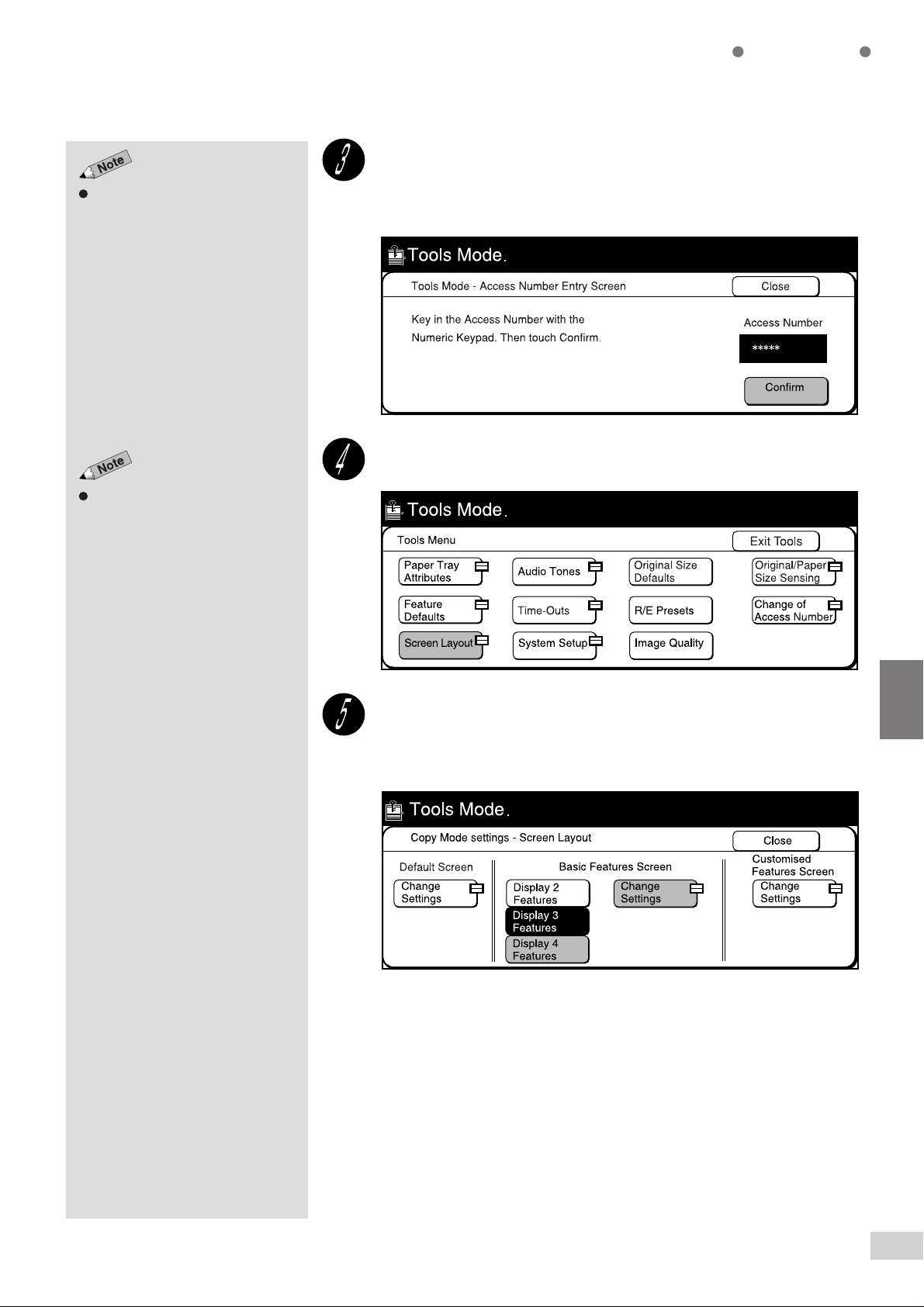
Displaying the Tools Mode
Screen
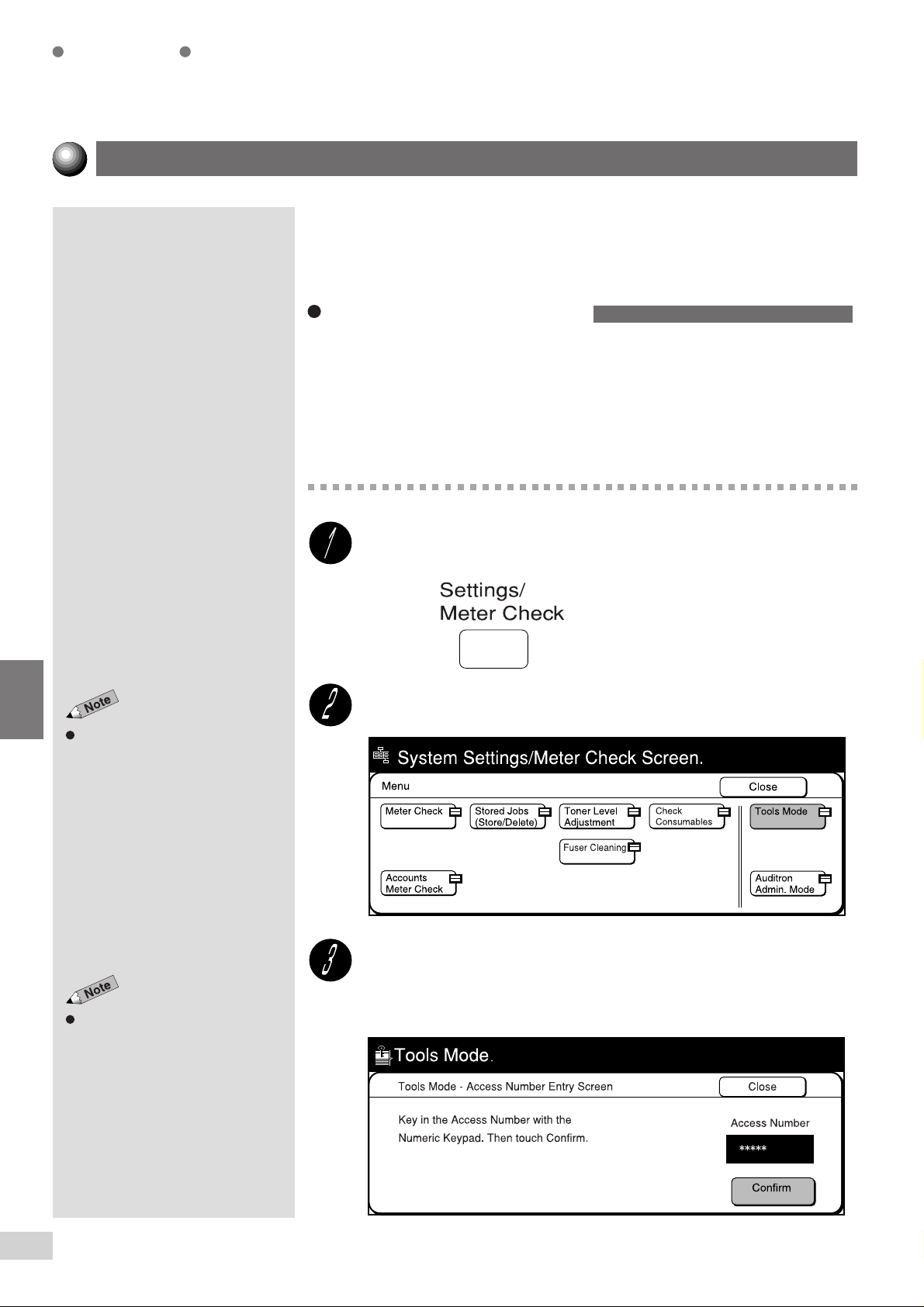
Displaying the Tools Mode Screen
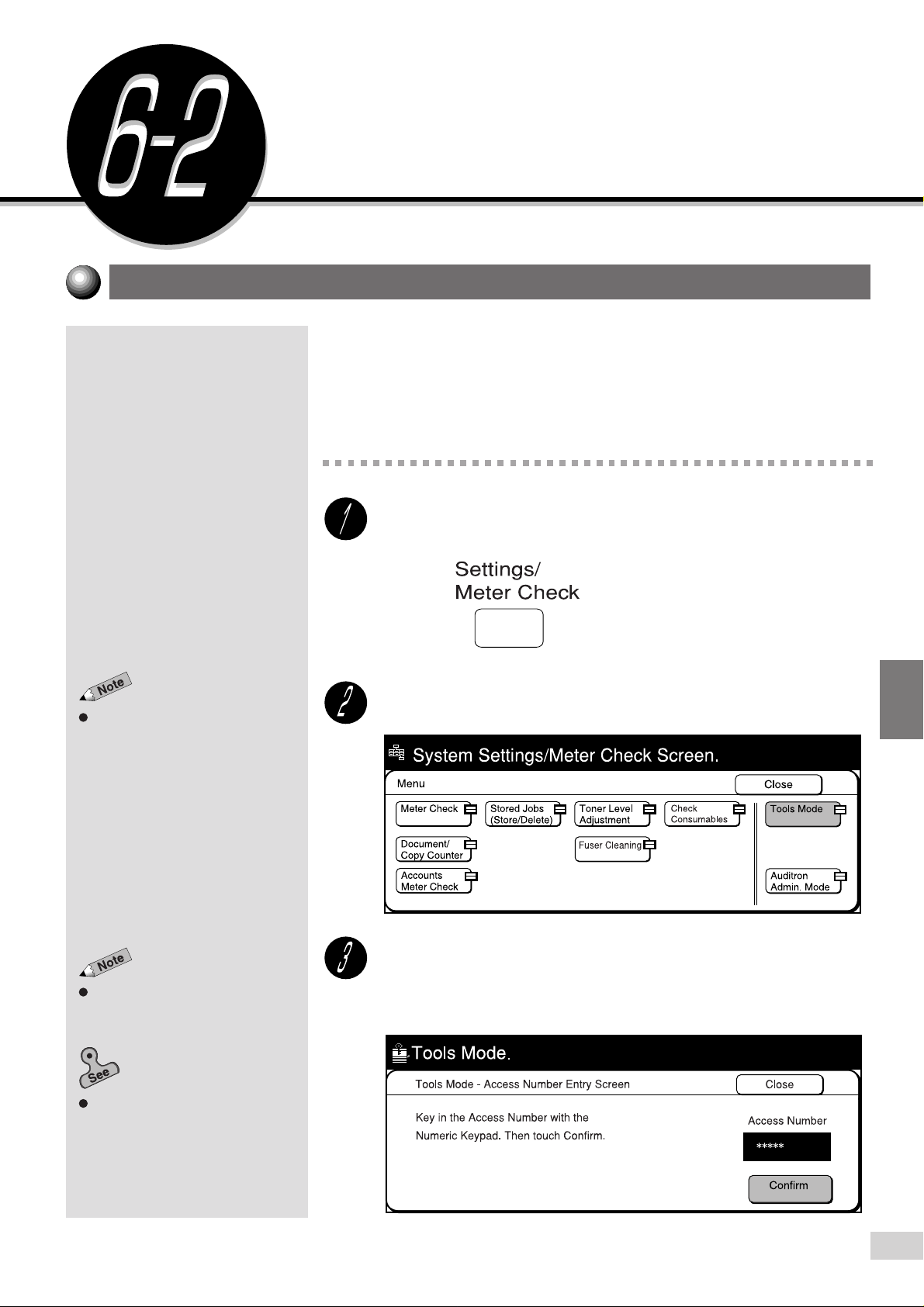
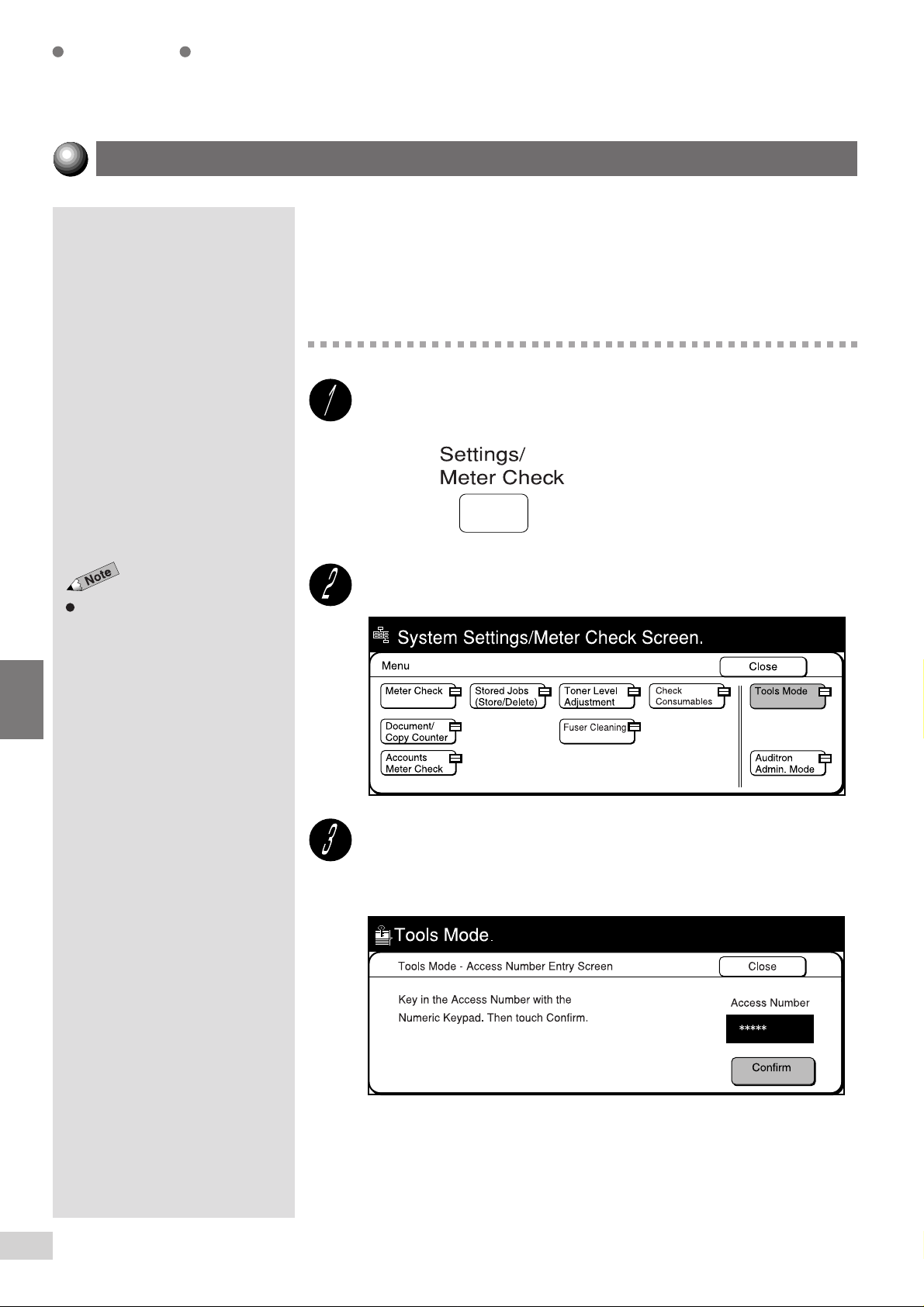
This section describes the procedures for displaying the Tools Mode screen.
You need to enter the Access Number of the System Administrator in order
to proceed with selecting the features on the Tools Menu.
The factory default for the Access Number is "11111".
Procedure
Custom Presets
The screen on the right is when the
Auditron feature is enabled. See
Chapter 9 Using the Auditron
Feature
for details.
If you made an error while entering
the Access Number, press the Clear
C button to clear and re-enter.
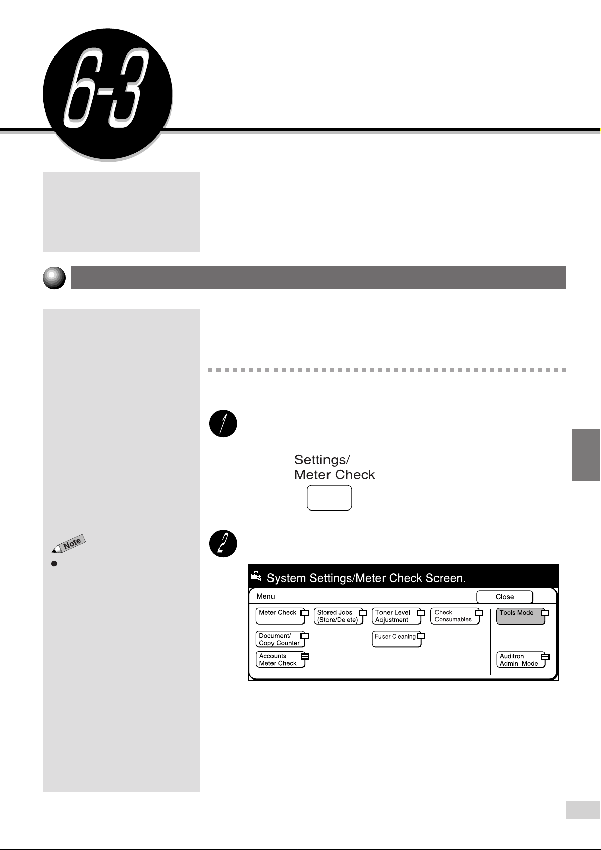
Press Settings/Meter Check.
Select Tools Mode.
Enter the Access Number of the System Administrator by
using the keypad and select Confirm.
Each input digit is represented by an asterisk.
6
Changing the
administrator
Machine with Tools Mode
information on how to change the
Access Number.
Access Number
in
6-3: Configuring the
for
of the
6-2 Displaying the Tools Mode Screen
147
Page 10
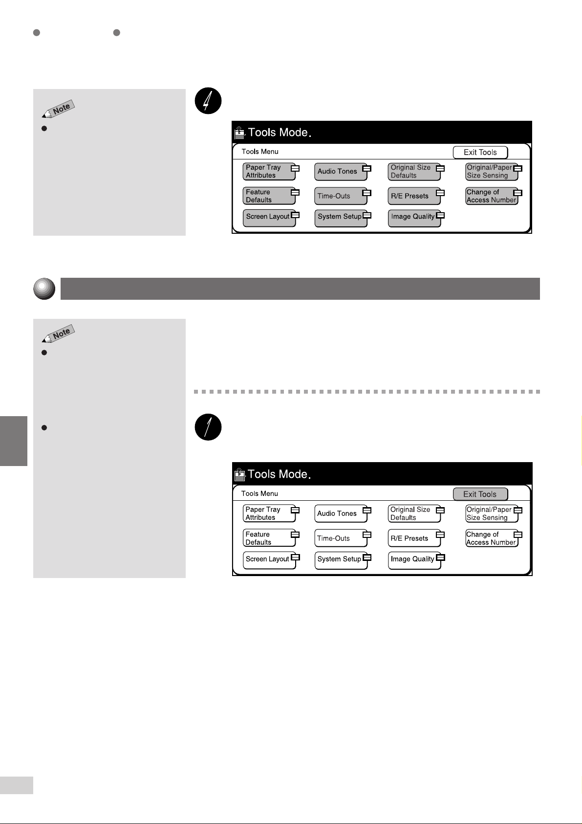
Custom Presets
Select an item to change its settings.
For models with the printer feature,
the screen displayed differs.
Exiting the Tools Mode Screen
6
If default time of System Admin.
Mode Exit Timer is defined in Time-
Outs, the machine will exit the mode
once the set time has elapsed and
the default screen will be redisplayed. The factory default is 10
minutes.
You will hear the Machine Ready
Tone when the machine returns to
the default screen. This is not an
error.
You can return to the default screen by the following procedures once you
have selected the required features.
Procedure
Select Exit Tools on the Tools Mode screen.
The default screen re-appears.
6-2 Displaying the Tools Mode Screen
148
Page 11
Configuring the Machine with
Tools Mode
This section uses the three examples described below to explain the
procedures for configuring Tools Mode.
Selecting the feature defaults
•
Changing the Access Number of the administrator
•
Configuring a screen (default/basic/customized)
•
Selecting the Feature Defaults
This section describes the procedures for selecting the feature defaults.
The example here is to change the default copy density to Darkest.
Custom Presets
The screen on the right is when the
Auditron feature is enabled. See
Chapter 9 Using the Auditron
Feature
for details.
Procedure
Procedure
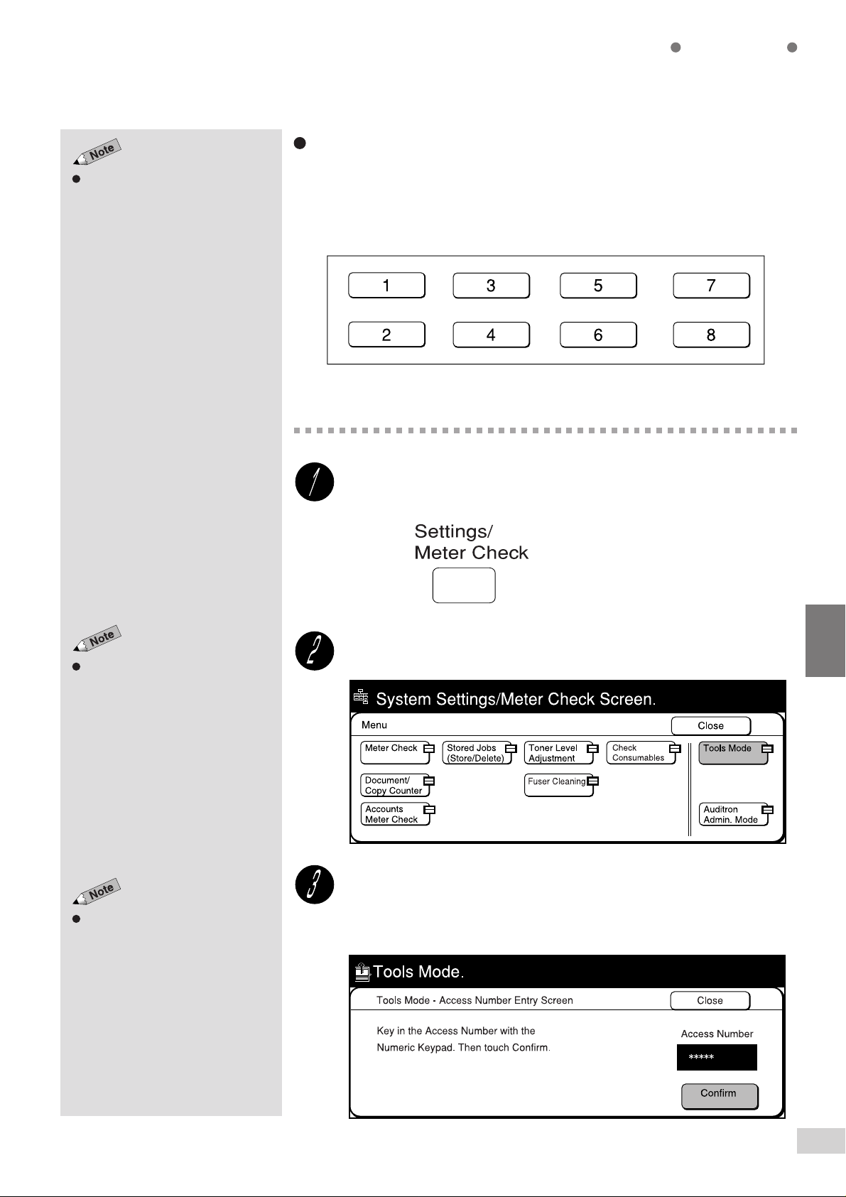
Press Settings/Meter Check.
6
Select Tools Mode.
6-3 Configuring the Machine with Tools Mode
149
Page 12
Custom Presets
The factory default of the access
number is "11111".
For models with the printer feature,
the screen displayed differs.
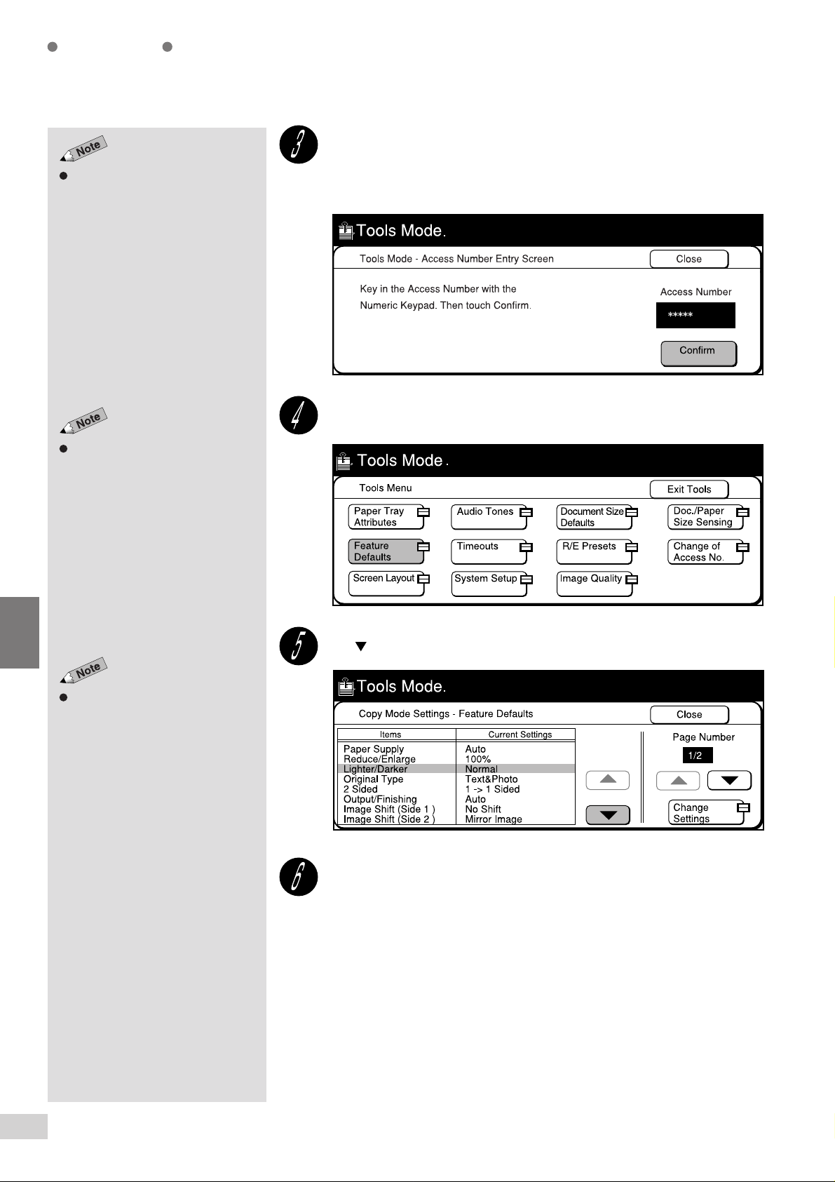
Enter the Access Number of the System Administrator and
select Confirm.
Each input digit is represented by an asterisk.
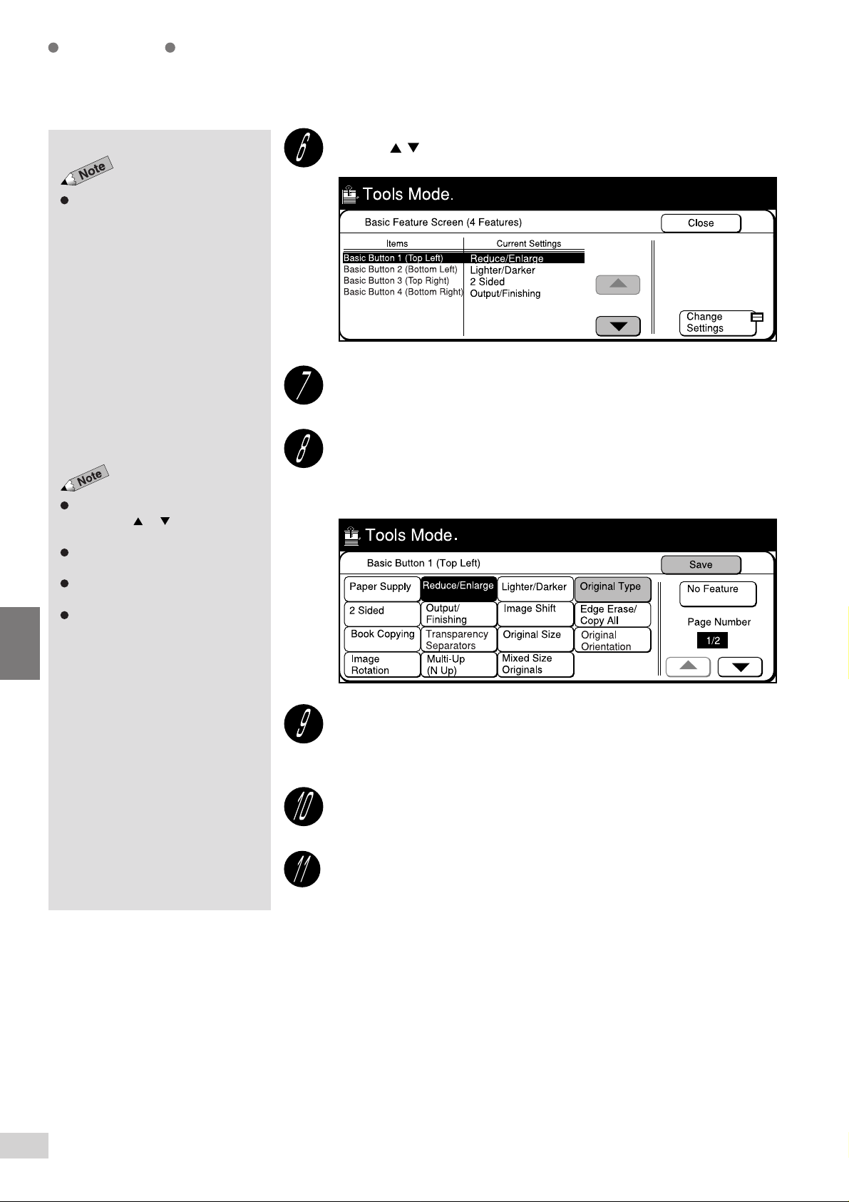
Select Feature Defaults.
6
Use to select Lighter/Darker.
You can also select Lighter/Darker
directly by touching it.
Select Change Settings.
6-3 Configuring the Machine with Tools Mode
150
Page 13
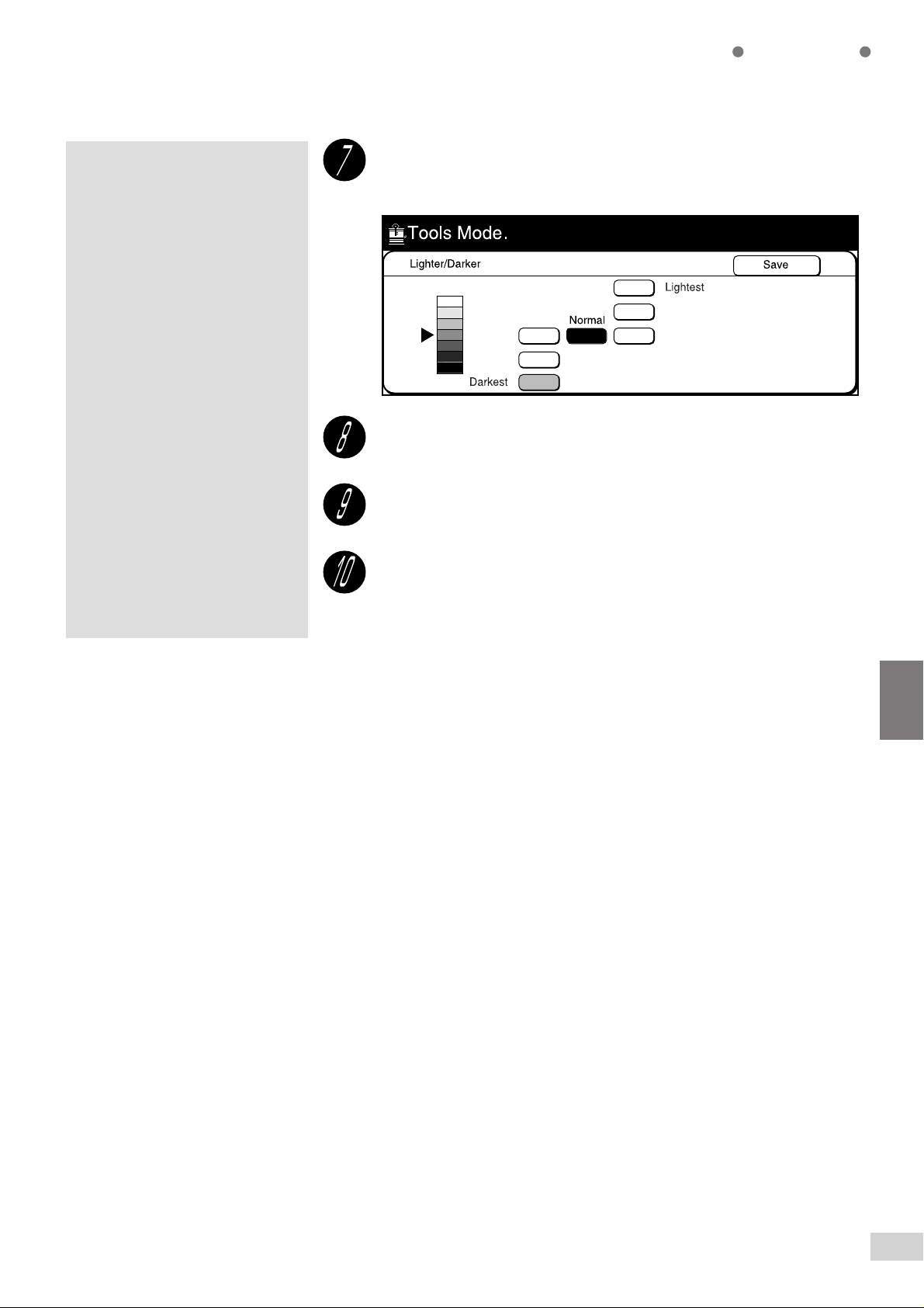
Select the default value of Lighter/Darker.
For example, select Darkest.
Select Save.
Custom Presets
Select Close until the screen shown in Step 4 is displayed.
Select Exit Tools.
The default value of Lighter/Darker is set.
6
6-3 Configuring the Machine with Tools Mode
151
Page 14
Custom Presets
Changing the Access Number of the Administrator
This section explains the procedures for changing the Access Number of the
administrator. The factory default is "11111".
If you have changed the Access Number, make sure that you keep a record
of the new number.
Procedure
Press Settings/Meter Check.
6
The screen on the right is when the
Auditron feature is enabled. See
Chapter 9 Using the Auditron
Feature
for details.
Select Tools Mode.
Enter the Access Number of the System Administrator and
select Confirm.
Each input digit is represented by an asterisk.
6-3 Configuring the Machine with Tools Mode
152
Page 15
For models with the printer feature,
the screen displayed differs.
If you made a mistake while entering
the Access Number, press the Clear
C button to clear and re-enter.
To reset the Access Number setting,
press Reset.
Custom Presets
Select Change of Access Number.
Enter the New Access Number by using the keypad. You can
enter between 4 to 12 digits. Then select Enter.
Enter the Access Number again, and select Enter.
Select Close until the screen shown in Step 4 is displayed.
Select Exit Tools.
The New Access Number of the System Administrator becomes valid.
6
6-3 Configuring the Machine with Tools Mode
153
Page 16
Custom Presets
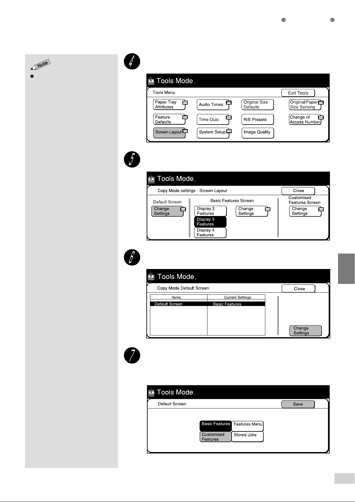
Configuring a Screen (Default/Basic/Customized)
This section explains the procedures for changing the default screen, and
customizing the Basic Features screen and the Customized Features
screen.
Changing the Default Screen
This feature allows you to display the desired screen when the power is
switched on, when it returns to the ready mode from the power saver
mode, or when Clear All is pressed.
The factory default screen is the Basic Features screen.
Procedure
6
The screen on the right is displayed
when the Auditron feature is
enabled. See
Auditron Feature
The factory default of the Access
Number is "11111".
Chapter 9 Using the
for details.
Press Settings/Meter Check.
Select Tools Mode.
Enter the Access Number of the System Administrator and
select Confirm.
Each input digit is represented by an asterisk.
6-3 Configuring the Machine with Tools Mode
154
Page 17
For models with the printer feature,
the screen displayed differs.
Custom Presets
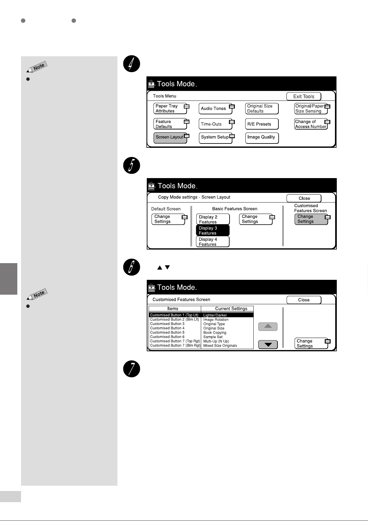
Select Screen Layout.
Select Change Settings in Default Screen.
Select Change Settings.
Select the screen to be displayed as the default screen and
select Save.
For example, select Customized Features.
6
6-3 Configuring the Machine with Tools Mode
155
Page 18
Custom Presets
Then select Close until the screen shown in Step 4 is
displayed.
Select Exit Tools.
The new default screen is defined.
Configuring the Basic Features Screen
6
Basic Features screen can display a
maximum of four feature buttons.
You can select to display two, three
or four features in the layouts shown
below.
The factory default is Display 3
Features.
This feature allows you to select the number of features to be displayed
on the Basic Features screen and which features to be displayed on
these basic buttons.
Display 2 Features
•
Assign the features to the two buttons (Feature Buttons 1 and 2)
Display 3 Features
•
Assign the features to Feature Button 1, Feature Button 2 and Feature
Button 3.
Display 4 Features
•
Assign the features to Feature Button 1, Feature Button 2, Feature
Button 3 and Feature Button 4.
Procedure
Press Settings/Meter Check.
The screen on the right is when the
Auditron feature is enabled. See
Chapter 9 Using the Auditron
Feature
for details.
6-3 Configuring the Machine with Tools Mode
156
Select Tools Mode.
Page 19
The factory default of the access
number is "11111".
For models with the printer feature,
the screen displayed differs.
Custom Presets
Enter the Access Number of the System Administrator and
select Confirm.
Each input digit is represented by an asterisk.
Select Screen Layout.
Select the number of features to be displayed on the Basic
Features screen and select Change Settings.
For example, select Display 4 Features.
6
6-3 Configuring the Machine with Tools Mode
157
Page 20
6
Custom Presets
Use the buttons to select the desired basic button.
You can also select the basic button
directly by touching it.
Select Change Settings.
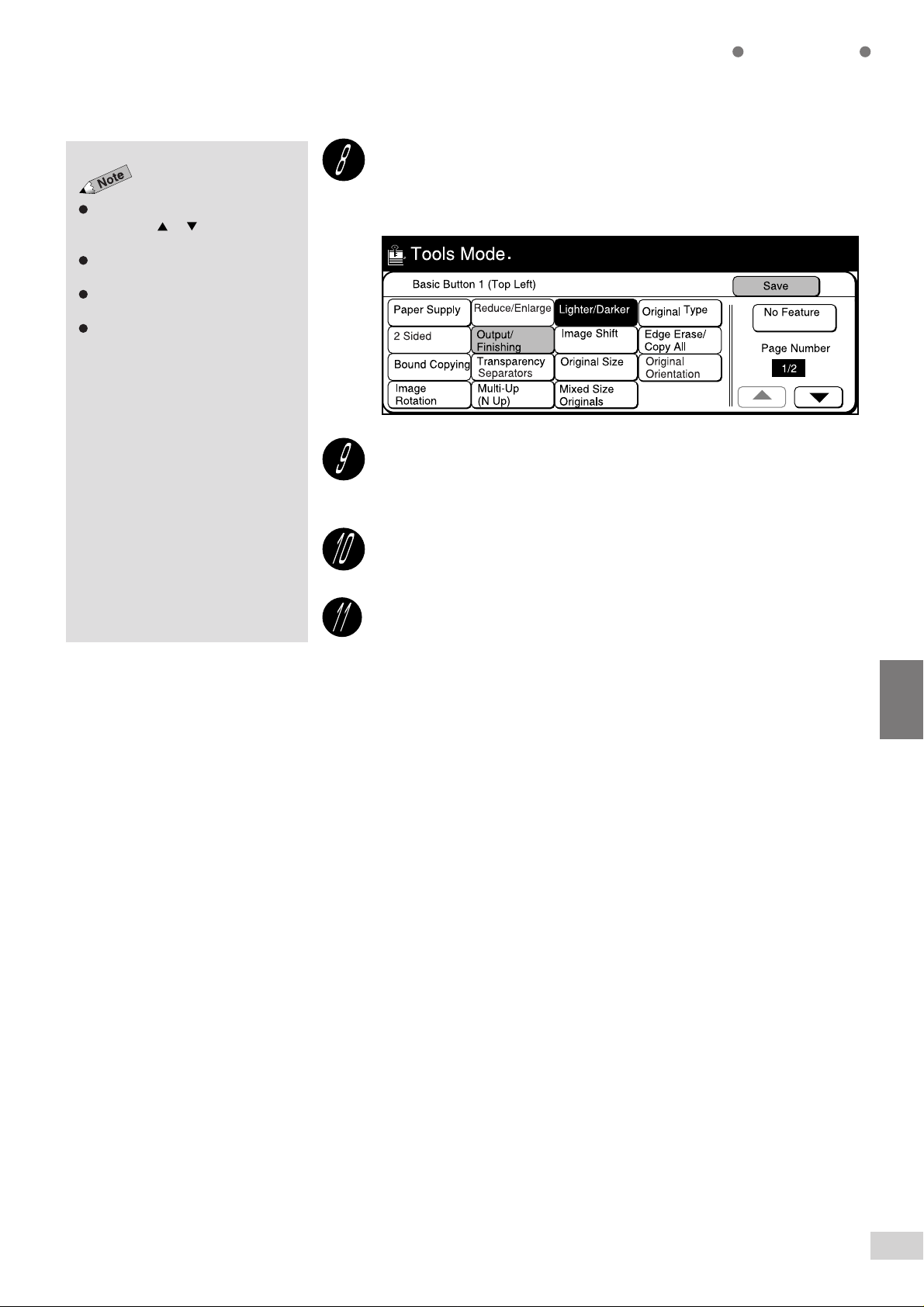
Select the feature to be displayed in the selected basic button
and select Save.
For example, select Original Type.
The buttons are displayed on two
pages. Use or buttons to page
up or page down.
Select No Feature if you do not wish to
assign any feature to the button.
Buttons that are unavailable are dim
and grey in color.
The screen on the right has the
Finisher installed.
Repeat Steps 6 to 8 when necessary to assign the required
features to all the basic buttons.
Select Close until the screen shown in Step 4 is displayed.
Select Exit Tools.
6-3 Configuring the Machine with Tools Mode
158
Page 21
Select No Feature if you do not wish to
assign any feature to the button.
Custom Presets
Configuring the Customized Features Screen
This feature allows you to assign the customized features to be displayed
on the Customized Features screen. You can assign a maximum of eight
buttons on this screen.
The eight buttons of Customized Features are arranged as follows.
Procedure
The screen on the right is when the
Auditron feature is enabled. See
Chapter 9 Using the Auditron
Feature
for details.
The factory default of the access
number is "11111".
Press Settings/Meter Check.
Select Tools Mode.
Enter the Access Number of the System Administrator by using
the keypad and select Confirm.
Each input digit is represented by an asterisk.
6
6-3 Configuring the Machine with Tools Mode
159
Page 22
Custom Presets
For models with the printer feature,
the screen displayed differs.
Select Screen Layout.
Select Change Settings in Customized Features screen.
6
Use to select the desired customized button.
You can also select the customized
button directly by touching it.
Select Change Settings.
6-3 Configuring the Machine with Tools Mode
160
Page 23
The buttons are displayed on two
pages. Use or buttons to page
up or page down.
Select No Feature if you do not wish to
assign any feature to the button.
Buttons that are unavailable are dim
and grey in color.
The screen on the right has the
Finisher installed.
Custom Presets
Select the feature to be displayed in the selected customized
button and select Save.
For example, select Output/Finishing.
Repeat Steps 6 to 8 when necessary to assign the required
features to all the customized buttons.
Select Close until the screen shown in Step 4 is displayed.
Select Exit Tools.
6
6-3 Configuring the Machine with Tools Mode
161
Page 24

This page is intentionally left blank.
Page 25

7
Troubleshooting
7-1 Troubleshooting .......................................................... 164
7-2 Paper Jams................................................................. 168
7-3 Document Jams .......................................................... 183
7-4 Stapler Faults.............................................................. 189
Page 26
Troubleshooting
Troubleshooting
This section describes the troubleshooting methods in the event of an error.
A message will be shown on the display if paper is jammed or there is an
internal machine fault. Follow the displayed instructions to identify the
problems and troubleshoot. Contact your local authorized Panasonic
service representative if any problem persists even after you have tried the
following solutions.
When an Error Message is Displayed
7
If error messages are displayed when an error occurred, follow the
messages to resolve the problem. If "Paper Jam" or "Document Jam" is
displayed, See
7-2: Paper Jams
or
When Other Problems Occurred
Symptom Check Measure
"Ready to Copy", "Press Start
to continue or press C button to
cancel the job..." is not
displayed.
The copy is dirty. Is the document glass or the document
There are black lines on the
copy.
Is the power cord loose?
Is the power switch in the " " position?
cover dirty?
Is the document made of a transparent
material?
Is the document colored or of a rough
texture such as pulp paper or blueprint?
Is the document glass dirty? Clean the document glass.
7-3: Document Jams
Check that the power cord is plugged in
properly.
Check that the power switch is "|" (On).
Clean the document glass or the
document cover.
8-1: Cleaning the Copier
•
Marks on the document cover are copied if
the document is made of a transparent
material such as transparency. Place a
sheet of white paper over the document.
Adjust the copy density, or select Photo
for Original Type.
5-2: Adjusting Copy Density (Lighter/
•
Darker)
8-1: Cleaning the Copier
•
for details.
7-1 Troubleshooting
164
The copy is too dark. Is Lighter/Darker set at Darkest? Select a lighter copy density setting.
5-2: Adjusting Copy Density (Lighter/
•
Darker)
Page 27
Symptom Check Measure
Troubleshooting
The copy is too light. Is the density of the document too light?
Is copy density set at Lightest?
Is the document loaded correctly?The images on the copy are
skewed.
Is the document guide on the DADF at the
right position?
Is the paper loaded correctly in the tray?
Is the paper guide of Tray 5 (Bypass)
adjusted properly so that it touches the
paper?
Is the paper tray set properly?
Select a darker copy density setting.
Increase toner dispensing level if copy is
still light after adjusting the copy density.
5-2: Adjusting Copy Density (Lighter/
•
Darker)
8-3: Increasing the Toner Level
•
Load the document correctly.
3-2: Loading Documents
•
Load the document properly and ensure
that the guide touches the edge of the
loaded document.
Loading documents in the DADF
•
3-2: Loading Documents
Loaded the paper correctly.
2-3: Loading Paper
•
Adjust the paper guide so that it touches
the paper gently.
Loading paper in Tray 5 (Bypass) of
•
2-3: Loading Paper
Ensure that the paper tray is pushed in
completely.
2-3: Loading Paper
•
in
The copy is not made on paper
of the desired size.
Is the Document Glass or document cover
dirty?
Is the document a transparent material?
Is the document placed at the right
position?
Is the document guide of the DADF out of
position?
Is the Image Rotation feature set to On?
Has the document been
folded like the picture on
the right?
Is there anything
placed on the DADF?
Clean the document glass or document
cover.
8-1: Cleaning the Copier
•
Place the document on the document
glass. Then place a sheet of white paper
over the document.
Load the document correctly.
3-2: Loading Documents
•
Load document correctly by adjusting the
document guide to touch the edge of it.
3-2: Loading Documents
•
Set Image Rotation feature to Off.
5-11: Rotating and Copying in
•
Different Directions (Image Rotation)
Flatten the document and reload it.
Remove it.
7
7-1 Troubleshooting
165
Page 28
Troubleshooting
Symptom Check Measure
Part of the image is missing on
the copy.
Document is often jammed.
Is the paper damp?
Is the paper folded or wrinkled?
Is the DADF open?Document is not fed.
Is the document too small?
Is the right type of document used?
Is the document non standard, or are
documents such as name cards,
transparencies and thin paper used?
Are stickers, paper clips and cellophane
tapes attached to the document?
If the paper is damp, either some parts of
the copy are not shown or the copy is
smudged and unclear. Replace it with a
newly opened ream of paper.
2-3: Loading Paper
•
Replace the undesirable paper with paper
from a newly opened ream.
2-3: Loading Paper
•
Close the DADF.
The minimum size of document that can be
used on the DADF is A5 or 5.5 x 8.5".
3-1: Documents
•
Load documents that can be handled by
the DADF.
3-1: Documents
•
3-2: Loading Documents
•
Remove the stickers, clips and cellophane
tapes and copy again.
7
folded.
The scanning of the document
was stopped halfway.
The copier sometimes stops,
then starts again in the middle of
a copy job.
Is the document guide on the DADF in the
right position?
Is part of the document torn and the
pieces of paper still remaining in the
DADF?
Is the document curled?A corner of the document is
Did you load 51 sheets of documents or
more on the DADF?
This is normal operation.
Ensure that the document guide on the
DADF touches the edge of the document.
Loading documents in the DADF
•
3-2: Loading Documents
Open the cover of the DADF to check that
there are no torn paper.
7-3: Document Jams
•
Load the document again after you have
uncurled the document.
The maximum number of sheets that can
be loaded on the DADF is 50. When 51
sheets or more have to be loaded, divide
them into multiple jobs.
Loading documents in the DADF in
•
3-2: Loading Documents
To maximize image quality, the unit may
pause temporarily to optimize the imaging
process.
in
7-1 Troubleshooting
166
Page 29
Symptom Check Measure
Troubleshooting
Paper is often jammed or
wrinkled.
Is the paper loaded correctly in the tray?
Is the paper tray set correctly?
Is the paper in the paper tray folded or
wrinkled?
Is the paper curled?
Are there any torn pieces of paper still
remaining inside the machine or is there a
foreign object in the machine?
Is the paper damp?
Load the paper correctly.
2-3: Loading Paper
•
Ensure that the paper tray is pushed in
completely.
2-3: Loading Paper
•
Replace the undesirable paper with paper
from a newly opened ream.
2-3: Loading Paper
•
Turn the paper over in the tray or replace
the undesirable paper with paper from a
newly opened ream.
2-3: Loading Paper
•
Open the machine door or pull out the
paper tray to remove the torn paper.
7-2: Paper Jams
•
Replace the undesirable paper with paper
from a newly opened ream.
2-3: Loading Paper
•
Is out-of-spec paper loaded in the tray?
Is paper loaded above the Max fill line? Load paper below the Max fill line.
Stapling is not done. Are the staples jammed? Remove the jammed staples.
The copies are not stapled or
punched at the right positions.
Even when Start is pressed,
copying is unable to start, or
“Unable to start, there is a job in
the queue. Select Job Status
Stop to check.“ is displayed.
Is the document set in the Head to Left
orientation?
Is there a job in the queue?
Replace with paper of right specifications.
2-1: What Paper to Use
•
2-3: Loading Paper
•
2-1: What Paper to Use
•
7-4: Stapler Faults
•
Select Head to Left on the screen.
Press Job Status Stop and select the
job. Press Clear C, or Clear All to cancel
the job. To resume the job, press Start.
4-11: Stopping a Copy Job
•
Time-Outs of 6-1: List of Custom
•
Preset Functions
7
7-1 Troubleshooting
167
Page 30
Troubleshooting
Do not open the cover if you see
smoke emitting as a result of a
paper jam. Immediately switch off
the power and disconnect the power
cord. Then contact your local
authorized Panasonic service
representative.
Paper Jams
Once a paper jam is detected, the machine will stop and an error message
will be shown on the display.
Follow the instructions on the display to remove the jammed paper.
This section describes how to remove jammed paper from the following
locations:
Trays 1-4
•
Tray 5 (Bypass)
•
Tray 6 (High Capacity Feeder)
•
Lower Right Cover of the Machine
•
Inside the Machine
•
Output Tray
•
Inside the Finisher
•
Finisher Tray
•
Sometimes paper may be jammed at more than one location. In this case,
error messages will continue to be displayed even after you have removed
the jammed sheet of paper from a particular location. Follow the
instructions on the display to locate the other jammed sheets of paper.
7
When removing jammed paper, make sure that no pieces of
torn paper are left in the machine. A piece of paper remaining in
the machine can cause fire.
If a piece of paper is wrapped around the heat roller, or when
clearing a jammed paper that is difficult or impossible to see,
do not try to remove it by yourself. Doing so can cause
injuries or burns. Switch off the machine immediately, and
contact your local authorized Panasonic service
representative.
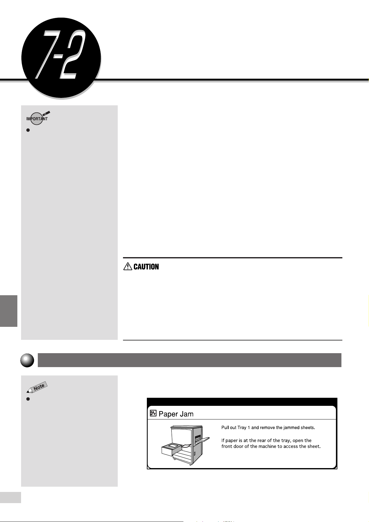
Paper Jam at Trays 1-4
The following messages will be shown on the display if paper is jammed at
Trays 1 to 4.
The screen on the right shows the
error messages indicating that paper
is jammed at Tray 1. The error
messages shown will depend on
the tray that paper jam occurred.
7-2 Paper Jams
168
Page 31

Troubleshooting
Remove the jammed paper by following the procedures shown below.
Procedure
Pull out the paper tray that
is shown on the display.
Remove the jammed
paper.
Push the tray in slowly until
This message will not appear and
the machine will not resume its
operation if the tray is not closed
properly. If sheets of paper are also
jammed at other locations, other
error messages will be displayed.
it stops.
"Ready to copy. Press Start to
continue or press C button to
cancel the job." is displayed once
you have removed the paper and
pushed the tray in.
Paper Jam at Tray 5 (Bypass)
The following messages will be shown on the display if paper is jammed at
Tray 5 (Bypass).
7
7-2 Paper Jams
169
Page 32

Troubleshooting
Remove other paper loaded in the
tray before clearing the paper jam.
After the jam is cleared, “Ready to
copy. Press Start.” is displayed.
Procedure
Remove the jammed
paper, which is fed
halfway, from the tray.
If the paper is torn, check that
there is no remaining pieces of
paper in the machine.
Move the center lever
towards you and pull out
the tray until it stops.
7
Remove the jammed
paper.
Push the tray all the way
in.
To continue copying, reload the
paper in the correct way.
Paper Jam at Tray 6 (High Capacity Feeder)
The following messages will be shown on the display if paper is jammed at
Tray 6 (High Capacity Feeder).
7-2 Paper Jams
170
Page 33

Troubleshooting
Follow the instructions on the screen, and Procedures A-C to remove
jammed paper.
Procedure A
Open Tray 5 (Bypass) by
the grip on the left.
Move the center Lever
towards you and pull out
the tray until it stops.
Top cover cannot be opened when
Tray 5 (Bypass) is open. Close Tray
5 (Bypass) before opening the Top
Cover.
Remove the jammed
paper.
7
Push the tray all the way in.
Procedure B
Open the Top Cover of
Tray 6 (High Capacity
Feeder).
7-2 Paper Jams
171
Page 34

Troubleshooting
Lift the jammed paper.
Close the Top Cover.
7
Procedure C
Pull out Tray 6 (High
Capacity Feeder).
Remove the jammed
paper.
7-2 Paper Jams
172
Push Tray 6 (High
Capacity Feeder) all the
way in.
Page 35

Troubleshooting
Paper Jam at Lower Right Section of the Machine
The following messages will be shown on the display if paper is jammed at
the lower right section of the machine.
When these messages appear, follow the instructions in Steps 1 and 2 to
remove the jammed paper.
When these messages appear, follow the instructions from Steps 1 to 5.
Procedure
Push down on the Release
Latch on the Lower Right
Cover of the machine to
open it.
7
7-2 Paper Jams
173
Page 36

Troubleshooting
Remove the jammed paper
slowly.
If the paper could not be
removed in Step 2, pull up the
Green Lever (as indicated by
the arrow on the upper right
hand side of the cover) to
open the Inner Cover .
7
If the cover is not closed completely,
error messages will continue to be
shown on the display and the
machine will not resume its
operation. If sheets of papers are
still jammed at other locations, other
error messages will be displayed.
"Ready to copy. Press Start to
continue or press C button to cancel
the job." is displayed once the
jammed paper is removed.
Remove the jammed paper
slowly.
Close the Inner Cover
completely until you hear
the click sound.
Close the Lower Right Cover of the machine.
7-2 Paper Jams
174
Page 37

Paper Jam Inside the Machine
The following messages will be shown on the display if paper is jammed
inside the machine.
The error messages shown on the
right indicate that paper jam has
occurred at four locations, namely,
1, 2, 3 and 4 inside the machine.
The error messages shown differ
depending on the location where the
error occurred.
Follow the steps below to remove jammed paper.
Troubleshooting
Procedure
Open the Front Door.
Turn the Green Lever at
the center of the transfer
unit clockwise until it is in
the horizontal position.
Then pull the Transfer Unit
out slowly until it stops.
When pulling out the
Transfer Unit, be
careful that your
fingers are not hurt
by the pincers.
7
7-2 Paper Jams
175
Page 38

Troubleshooting
Remove the jammed paper
on the top right of the
Transfer Unit.
If the paper cannot be removed
easily, turn Knob 5 counterclockwise to eject the jammed
paper.
Do not put your
•
fingers inside the
Transfer Unit. You
may get hurt.
Never touch a labelled
•
area found on or near
the fuser unit. You can
get burnt.
7
Remove the jammed paper
while lifting Lever 1.
If the paper cannot be removed
easily, turn Knob A counterclockwise to eject the jammed
paper.
Remove the jammed paper
while pushing Lever 2
downwards.
Lift Lever 3 to remove the
jammed paper.
7-2 Paper Jams
176
Page 39

If the door is not closed completely,
error messages will continue to be
shown on the display and the
machine will not resume its
operation. If sheets of papers are
still jammed at other locations, other
error messages will be displayed.
"Ready to copy. Press Start to
continue or press C button to cancel
the job." is displayed once the
jammed paper is removed.
Troubleshooting
Push Lever 4 to the right to
open the paper guide on
the right side of the
transfer unit.
Push in the transfer unit
until it stops and turn the
Green Lever counterclockwise until you hear a
click sound.
If the lever does not turn,
pull out the transfer unit
halfway and then push it in
again.
Close the Front Door.
7
7-2 Paper Jams
177
Page 40

Troubleshooting
Paper Jam at the Output Tray
The following messages will be shown on the display if paper is jammed at
the output area during a copy job.
When these messages appear, follow the instructions from Steps 1 to
4 to remove the jammed paper.
7
When these messages appear, follow the instructions in Step 1 and after
Step 5 to remove the jammed paper.
Procedure
Remove the jammed paper
by pulling it out slowly from
the Output Tray.
7-2 Paper Jams
178
If it cannot be removed,
push down on the Release
Latch on the Lower Right
Cover of the machine to
open it.
Page 41

If the cover is not closed completely,
error messages will continue to be
shown on the display and the
machine will not resume its
operation. If sheets of papers are
still jammed at other locations, other
error messages will be displayed.
"Ready to copy. Press Start to
continue or press C button to cancel
the job." is displayed once the
jammed paper is removed.
Troubleshooting
Remove the jammed paper
by pulling it out slowly.
Close the Lower Right
Cover of the machine.
If the paper cannot
be removed, open the
Front Door.
If the door is not closed completely,
error messages will continue to be
shown on the display and the
machine will not resume its
operation. If sheets of papers are
still jammed at other locations, other
error messages will be displayed.
"Ready to copy. Press Start to
continue or press C button to cancel
the job." is displayed once the
jammed paper is removed.
Turn Knob 5 clockwise and
remove the jammed paper
by pulling it out slowly.
Close the Front Door.
7
7-2 Paper Jams
179
Page 42

Troubleshooting
Paper Jam Inside the Finisher
The following messages will be shown on the display if paper is jammed
inside the Finisher (optional).
7
Follow the instructions below to remove the jammed paper.
Procedure
Hold the handle of the
Finisher and open its top
cover.
Remove the jammed
paper.
When making large volume output,
do not touch the area affixed with
the CAUTION label.
7-2 Paper Jams
180
If the jammed paper could
not be removed easily, turn
Knob 8 counter-clockwise
to eject the paper.
Page 43

Close the Top Cover of the
If the cover is not closed completely,
error messages will continue to be
shown on the display and the
machine will not resume its
operation. If sheets of paper are still
jammed at other locations, other
error messages will be displayed.
Finisher.
Paper Jam at the Finisher Tray
The following messages will be shown on the display if paper is jammed at
one of the Finisher (optional) Trays.
Troubleshooting
Follow the instructions below to remove the jammed paper.
Procedure
Lift Cover 9 at the output
area of the Finisher as
indicated in the diagram.
Remove the jammed
paper.
7
7-2 Paper Jams
181
Page 44

Troubleshooting
If the cover is not closed completely,
error messages will continue to be
shown on the display and the
machine will not resume its
operation. If sheets of paper are still
jammed at other locations, other
error messages will be displayed.
If the jammed paper could
not be removed easily,
open the Front Door of the
Finisher and turn Knob 10
counter-clockwise to eject
the paper.
Close the Front Door.
If the message is still
displayed even though the
jammed paper is removed,
lift up and lower Cover 9
again.
7
7-2 Paper Jams
182
Page 45

Troubleshooting
Document Jams
The following messages will be shown on the display when the machine
stops as the document is jammed at the DADF.
Follow the instructions on the display to remove the jammed document.
After you have removed the jammed document, follow the instructions on
the display and load your document again in the DADF.
Document Jam at the Feeding Point of the DADF
The following messages will be shown on the display if the document is
jammed at the feeding point of the DADF.
Procedure
Lift the Release Latch at
the center of the DADF
and open the Left Cover
completely.
7
7-3 Document Jams
183
Page 46

Troubleshooting
Remove the jammed
document.
Close the Left Cover of the
DADF until you hear a click
sound.
7
Check if the document is
A torn, wrinkled, or folded document
will cause it to be jammed at the
DADF. In such a case, place the
document directly on the Document
Glass.
torn, wrinkled, or folded. If
not, follow the instructions
on the display and re-load
the document in the DADF.
Document Jam Inside the DADF
The following messages will be shown on the display if the document is
jammed inside the DADF.
7-3 Document Jams
184
Page 47

The cover will be stationary when it
is fully open.
Troubleshooting
Procedure
Lift the Release Latch at
the center of the DADF
and open the Left Cover
completely.
Lift the Lever with the
Green Seal to open the
inner cover.
A torn, wrinkled, or folded document
will cause it to be jammed at the
DADF. In such a case, place the
document directly on the Document
Glass.
Remove the jammed
document.
7
Close the Inner Cover.
Then close the Left Cover
of the DADF until you hear
a click sound.
Check if the document is
torn, wrinkled, or folded. If
not, follow the instructions
on the display and re-load
the document in the DADF.
7-3 Document Jams
185
Page 48

Troubleshooting
Document Jam at the Document Tray
The following messages will be shown on the display if the document is
jammed at the Document Tray.
7
If the following messages are shown, refer to the descriptions in the
previous section to remove the jammed document from the feeding point of
the DADF. When the message(s) appear, remove the jammed document
from the Document Tray.
Procedure
Remove the document
from the Document Tray.
7-3 Document Jams
186
Page 49

Lift the Document Tray and
remove the jammed
document.
Put the Document Tray
slowly back in place.
Troubleshooting
Check if the document is
A torn, wrinkled, or folded document
will cause it to be jammed at the
DADF. In such a case, place the
document directly on the Document
Glass.
torn, wrinkled, or folded. If
not, follow the instructions
on the display and re-load
the document in the DADF.
Document Jam Underneath the DADF
The following messages are shown on the display if the document is
jammed underneath the DADF.
7
7-3 Document Jams
187
Page 50

Troubleshooting
Procedure
Lift the DADF slowly.
Remove the jammed
document.
If the document cannot be taken
out easily, turn the Knob
clockwise to remove it.
7
A torn, wrinkled, or folded document
will cause it to be jammed at the
DADF. In such a case, place the
document directly on the Document
Glass.
Put the DADF slowly back
in place.
Check if the document is
torn, wrinkled, or folded. If
not, follow the instructions
on the display and re-load
the document in the DADF.
7-3 Document Jams
188
Page 51

Troubleshooting
Stapler Faults
This section explains the methods used to resolve stapling problems at the
Finisher (optional). Follow the procedures on the following page to
troubleshoot problems such as faulty stapler and bent staples.
Contact your local authorized Panasonic service representative if the
staples are stapled on the copies in the manner as shown in the diagrams
below.
7
Contact your local authorized
Panasonic service representative if
the problems could not be resolved
even after trying out the solutions
described on the next page.
7-4 Stapler Faults
189
Page 52

Troubleshooting
If pressing the Orange Lever does
not free the staple cartridge, use
your hand to remove it.
Procedure
Open the Front Door of the
Finisher.
Press the Orange Lever as
shown in the diagram and
pull out the Staple
Cartridge.
7
Contact your local authorized
Panasonic service representative if
the problems could not be resolved
even after trying out the solutions
described on the right.
Open the cover of the
staple cartridge as shown
in the diagram and remove
the jammed staples.
When removing
jammed staples, take
care not to injure
your fingers.
If the staples could not be
removed, push in the
direction of the arrow to
remove the staples.
7-4 Stapler Faults
190
Page 53

Push the Staple Cartridge
in until the Orange Lever
returns to its original
position.
Close the Front Door of the
Finisher.
Troubleshooting
7
7-4 Stapler Faults
191
Page 54

This page is intentionally left blank.
Page 55

8
Daily Care
8-1 Cleaning the Copier .................................................... 194
8-2 Consumables.............................................................. 197
8-3 Increasing the Toner Level.......................................... 198
8-4 Replacing the Toner Cartridge .................................... 200
8-5 Replacing the Drum Cartridge .................................... 203
8-6 Replacing the Staple Cartridge................................... 206
8-7 Emptying the Punch Scrap Container......................... 208
8-8 Checking the Billing Meter .......................................... 210
8-9 Making Clean Copies.................................................. 212
Page 56

Daily Care
Cleaning the Copier
In order that clean copies can be made each time, you are recommended to
clean the following areas of the machine once a month.
Document Cover/Document Glass/DADF Scanning Glass
•
DADF Film/Roller sections
•
Cleaning Document Cover, Document/Scanning Glass
Procedure
8
The Document Cover is the part
where the DADF Belt is located.
If the Document Cover or Glass is
dirty, copies made will also be dirty
and it may affect the automatic
sensing of document sizes.
If the Scanning Glass of the DADF is
dirty, it will cause document jams
and result in dirty copies being
made.
Plastic and painted parts may be
damaged if you use benzine or
thinner to clean the machine.
If too much water is used, it will
damage the document or cause the
machine to fail.
Use a cloth that has been wrung
thoroughly and does not drip. Water
droplets seeping into the machine
will cause it to fail.
Lift the DADF slowly.
DADF will be stationary if fully
open.
Use a cloth made of soft
material, and moistened
with mild detergent.
Clean the Document Glass.
Clean the Document Cover.
8-1 Cleaning the Copier
194
Clean the DADF
Scanning Glass.
Page 57

Use a dry cloth made of soft material to wipe.
Put the DADF slowly back
in place.
Cleaning the DADF Film/Roller Sections
Daily Care
If the film and roller sections of the
DADF are dirty, they will cause
document jams and result in dirty
copies being made.
Procedure
Lift the Release Latch at
the center of the DADF
and open the Left Cover
completely.
Cover will be stationary
when fully open.
Lift the Lever with the
Green Seal to open the
inner cover.
8
Plastic and painted parts may be
damaged if you use benzine or
thinner to clean the machine.
If too much water is used, it will
damage the document or cause the
machine to fail.
Use a cloth that has been wrung
thoroughly and does not drip. Water
droplets seeping into the machine
will cause it to fail.
Use a moistened and soft
cloth to clean the rollers
(total 18). Clean them by
gently turning the rollers
with the cloth.
8-1 Cleaning the Copier
195
Page 58

Daily Care
Close the Inner Cover.
Then close the Left Cover
of the DADF until you hear
a click sound.
Lift the DADF slowly.
8
Do not press hard on the film as the
film section is very delicate.
Clean the rollers by turning them.
Use a moistened and soft
cloth to clean the film
section and the roller
section (total 8).
Use a dry cloth made of
soft material to wipe.
Put the DADF slowly back
in place.
8-1 Cleaning the Copier
196
Page 59

Consumables
Types of Consumables
Daily Care
The warranty does not cover
machine faults resulting from usage
of Non-Panasonic recommended
consumables.
The following consumables are available for this machine.
Ensure that the following consumables are used as this machine has
been developed according to the strictest regulations.
Use Panasonic-recommended consumables as nonrecommended ones may affect quality and performance of the
machine.
Consumables Package Product Code
Drum Cartridge One per box DQ-UH700
Toner Cartridge One per box DQ-TX281
Developer One per box DQ-ZX700
Staple Cartridge 5000 x 3 per box FQ-SS66
Handling Consumables
Do not place the boxes of consumables vertically.
Open the consumables only when you need to use them. Do not store
them in the following places:
Hot and humid places
•
Near a fire
•
Under direct sunlight
•
Dusty places
•
Follow the instructions and warning notes on the boxes or containers
of the consumables when using them.
Keeping an extra box of consumables is recommended.
Check the product code of the consumables and contact your local
authorized Panasonic service representative to place your orders.
8
8-2 Consumables
197
Page 60

Daily Care
5-2: Adjusting Copy Density
(Lighter/Darker)
how to adjust the copy density.
for information on
Increasing the T oner Level
If you find that copies made are too light, you can increase the copy density
by adjusting the toner level. This feature can be used besides the Lighter/
Darker feature to adjust the copy density. However, normally there is no
need to use this feature because the toner quantity of the developer unit is
automatically adjusted by the machine.
Procedure
8
The screen on the right is when the
Auditron feature is enabled. See
Chapter 9 Using the Auditron
Feature
for details.
Press Settings/Meter Check.
Select Toner Level Adjustment.
Select Start.
8-3 Increasing the Toner Level
198
Page 61

Daily Care
The following screen will be displayed for 40 seconds and the toner level will be
adjusted during this time.
No copy job can be done during this time.
After the toner level is adjusted, the default screen re-appears.
8-3 Increasing the Toner Level
8
199
Page 62

Daily Care
Do not place the used Toner
Cartridge which has just been
removed directly on the floor
because toner still remaining in the
cartridge may spill and dirty the floor.
You are recommended to spread
some paper on the floor before you
remove the cartridge.
Contact your local authorized
Panasonic service representative for
disposal of used Toner Cartridges.
Replacing the Toner Cartridge
The Toner Cartridge contains toner that decreases each time a copy is
made. When it is time for the Toner Cartridge to be replaced, the following
messages will be shown on the message area of the display. In this case,
follow the instructions to replace the Toner Cartridge.
Never throw a Toner Cartridge into an open flame. It can
cause an explosion and you can get burnt.
8
Use Panasonic-recommended Toner Cartridges as nonrecommended ones may affect quality and performance of
the machine.
Procedure
Check that the machine
has stopped and open the
Front Door.
8-4 Replacing the Toner Cartridge
200
Page 63

Remove the Toner Cartridge slowly
to avoid spilling the toner.
Daily Care
Hold the Orange Lever and
swing it to the left to open
the toner cartridge holder.
Turn the Toner Cartridge
counter-clockwise until you
hear a click sound. Then
pull the cartridge toward
you.
Contact your local authorized
Panasonic service representative for
disposal of used Toner Cartridges.
Lift the Toner Cartridge
and remove it from the
toner cartridge holder.
Never touch a
labelled area found on
or near the fuser unit.
You can get burnt.
Gently shake the new
Toner Cartridge from left to
right.
Align the mark on the
holder with the mark on
the new Toner Cartridge.
Then place the Toner
Cartridge on the holder.
8
8-4 Replacing the Toner Cartridge
201
Page 64

Daily Care
Push the Toner Cartridge
in and turn it clockwise
until it stops.
Hold the Orange Lever and
swing it back to the original
position until you hear a
click sound.
8
Close the Front Door.
If the door is not closed completely,
error messages will be shown on the
display and the machine will not
resume its operation.
8-4 Replacing the Toner Cartridge
202
Page 65

Replacing the Drum Cartridge
When the Drum Cartridge needs to
be changed, the message, “The
Drum Cartridge needs to be
replaced soon. Please call for
service.” will be displayed. If
copying is carried on in this
situation, the message, “The Drum
Cartridge needs to be replaced.
Jobs may stop printing halfway.
Please call for service.” will be
displayed. In this situation, you can
still continue to make copies but the
image quality will deteriorate with
each copy made, and finally the
machine will come to a stop.
Do not touch the drum parts when
you replace the Drum Cartridge.
Also, do not expose the drum to
direct sunlight or a bright light.
Contact your local authorized
Panasonic service representative for
disposal of used Drum Cartridges.
Daily Care
The Drum Cartridge is the photoreceptor for transferring the copy image
onto the paper. If you see the following messages displayed, follow the
instructions below to replace the Drum Cartridge.
Never throw a Drum Cartridge into an open flame. Toner
remaining in the cartridge can cause an explosion and you
can get burnt.
Use Panasonic-recommended Drum Cartridges as nonrecommended ones may affect quality and performance of
the machine.
Procedure
Turn the power switch to
" to switch Off the
"
power.
Open the Front Door.
8
8-5 Replacing the Drum Cartridge
203
Page 66

Daily Care
Hold the Orange Lever and
swing it to the left to open
the toner cartridge holder.
Turn the Green Lever at
the center of the transfer
unit clockwise until the
Lever is in the horizontal
position.
Slowly pull out about half
of the Drum Cartridge
while pressing the Orange
Button at the top of the
Drum Cartridge.
8
Contact your local authorized
Panasonic service representative for
disposal of used Drum Cartridges.
Never touch a labelled
area found on or near
the fuser unit. You can
get burnt.
Hold the handle at the top
and pull the Drum Cartridge
straight out.
Remove the new Drum
Cartridge from the
package and align the
Drum Cartridge with the
two rails.
8-5 Replacing the Drum Cartridge
204
Page 67

Do not touch the surface of the drum
as you may scratch or damage it.
Also, the drum may be dirtied in the
process making it difficult for the
machine to produce clean copies.
Daily Care
Push the drum in until you
hear a click sound.
Check that the Drum Cartridge
has been set properly.
Hold the Orange Lever and
swing it back to the original
position until you hear a
click sound.
Turn the Green Lever
counter-clockwise until the
click sound is heard.
Close the Front Door.
Turn the Power Switch to
the " | " position to switch
On the power.
Check that "Ready to copy" is
displayed.
8
8-5 Replacing the Drum Cartridge
205
Page 68

Daily Care
Replacing the Staple Cartridge
When it is time to replace the Staple Cartridge, the following messages will
be shown on the display. Follow the procedures below to replace the Staple
Cartridge. Contact your local authorized Panasonic service representative
when ordering a new Staple Cartridge.
8
If pressing the Orange Lever does
not free the cartridge, use your hand
to remove it.
Use Panasonic-recommended Staple Cartridges as nonrecommended ones may affect quality and performance of
the machine.
Procedure
Check that the machine
has stopped and open the
Front Door of the Finisher.
Press the Orange Lever as
shown in the diagram and
pull the Staple Cartridge
out.
8-6 Replacing the Staple Cartridge
206
Page 69

While pressing the position
as indicated by the right
arrow, pull to remove the
used Staple Case.
Insert a new Staple Case
into the Staple Cartridge.
Daily Care
Check that the Staple Cartridge is
inserted in the correct orientation.
Pull to remove the tab of
the Staple Case as shown
in the diagram.
Push the Staple Cartridge
back to its original position
until you hear a click
sound.
8
Close the Front Door of the
Finisher.
8-6 Replacing the Staple Cartridge
207
Page 70

Daily Care
Emptying the Punch Scrap
Container
When the optional Finisher with the Puncher is installed, the following
messages will be shown on the display when the punch scrap container is
full. Follow the steps to dispose of the scraps in the container.
Each time you pull the punch scrap container out from the machine, make
sure that all the scraps are emptied before you put the container back.
You should remove the container while the power is On. If you switch Off
the power and empty the scrap container, the machine will not be able to
detect that the container has been removed and the scraps disposed of.
8
Procedure
Open the Front Door of the
Finisher.
Pull the Punch Scrap
Container out in the
direction of the arrow.
8-7 Emptying the Punch Scrap Container
208
Page 71

You must dispose of all the scraps in
the container even if you have just
pulled the container out a little. This
is because the machine will sense
that the container has been pulled
out. If you do not dispose of the
scraps, the container may be full
before the next punch scrap
container disposal message is
displayed thus causing the machine
to fail.
Daily Care
Empty all the scraps.
Insert the Punch Scrap
Container and push it into
the machine.
Close the Front Door of the
Finisher.
8
8-7 Emptying the Punch Scrap Container
209
Page 72

8
Daily Care
The following types of copies are not
counted:
Blank sheets inserted by the
•
machine.
(A blank sheet is automatically
inserted if the total number of
sheets of the documents is an odd
number for 2 Sided.)
First and last blank pages when
•
making copies by using Book
Duplex feature.
Separators for transparencies
•
when the Transparency
Separators feature is used.
Jammed papers or partially done
•
copies as a result of machine fault.
Paper which is fed for fuser
•
cleaning
On a model with the printer function
installed, the number of copies
printed by using this function can be
displayed. To use this function,
contact your local authorized
Panasonic service representative.
Checking the Billing Meter
You can check the meter on the Settings/Meter Check screen.
Current Count....... Shows the number of copies made up till the present
time.
Procedure
Press Settings/Meter Check.
Select Meter Check.
9-3: Confirming the Account Data
for information on how to confirm the
account data of each user when the
Auditron feature is used.
The screen on the right is displayed
when the Auditron feature is
enabled. See
Auditron Feature
8-8 Checking the Billing Meter
210
Chapter 9 Using the
for details.
Page 73

Daily Care
Check the reading.
Select Close until the default screen is shown.
The Settings/Meter Check screen clears and the default screen re-appears.
8-8 Checking the Billing Meter
8
211
Page 74

Daily Care
The paper which is fed for fuser
cleaning depends on the sizes of
paper loaded in the trays. Paper will
be automatically fed based on the
following priority:
(1) One sheet of A3
(2) Two sheets of A4
(3) Two sheets of paper in portrait
orientation with greatest length.
The paper used for fuser cleaning
will not be recorded by the billing
meter.
Making Clean Copies
Regular cleaning of the internal parts of the machine helps in producing
clean copies every time. This machine is equipped with a feature that
allows plain paper to be fed for automatically removing dirt, which easily
accumulates on the fuser unit and other internal parts.
Procedure
If paper other than plain paper are loaded in the trays,
temporarily remove them. Confirm that plain paper is loaded in
any of the trays other than Tray 5 (Bypass).
Press Settings/Meter Check.
8
If your copy volume is large, it is
possible to set fuser cleaning to
activate automatically. Contact your
local authorized Panasonic service
representative.
8-9 Making Clean Copies
212
Select Fuser Cleaning.
Page 75

Daily Care
Select Start.
If fuser unit is not warmed up, wait a while for cleaning to begin.
The following screen is displayed while the fuser cleaning is in progress.
No copy job can be done during this time.
After the end of fuser cleaning, the Fuser Cleaning screen re-appears.
Select Close until the default screen is shown.
The Settings/Meter Check screen clears and the default screen re-appears.
8
8-9 Making Clean Copies
213
Page 76

This page is intentionally left blank.
Page 77

9
Using the Auditron Feature
9-1 Auditron ...................................................................... 216
9-2 Displaying the Auditron Administration Mode Screen . 218
9-3 Confirming the Account Data ...................................... 220
9-4 Editing the Account Data ............................................ 223
9-5 Deleting the Account Data .......................................... 227
9-6 Enabling/Disabling Auditron ........................................ 229
9-7 Defining Automatic Display of the Password Entry
Screen ........................................................................ 231
9-8 Changing the Auditron Access Number ...................... 233
Page 78

Using the Auditron Feature
9-4: Editing the Account Data
9-6: Enabling/Disabling Auditron
Auditron
When the Auditron mode is enabled, the copy volume of each account user
can be calculated. This is done by assigning a Password to each account
user.
The relationship between the Password Entry screen and a normal
screen is as shown below.
9
216
Using the Auditron Mode
In the Auditron Administration Mode, select On for Auditron Mode on the
Auditron Setup screen and register a Password for every account by using
the Create/Modify Accounts screen.
9-1 Auditron
Page 79

Using the Auditron Feature
The following operations can be done in the Auditron Administration mode.
2-sided copy volume and print
volume can be calculated. To use
this feature, contact your local
authorized Panasonic service
representative.
Copy limit refers to the setting of the
maximum number of copies which
can be made.
Item Description
Reviewing the Account Data The password, copy limit and current copy volume
settings can be reviewed for every account.
9-3: Confirming the Account Data
•
Creating/Modifying Account Data The password and copy limit of each account
can be created/modified.
Up to 300 accounts can be registered.
9-4: Editing the Account Data
•
Deleting the Account Data The copy volume, copy limit and password
settings of each account can be deleted for all
accounts and set to zero. You can also choose
to delete only the copy volume and copy limit.
9-5: Deleting the Account Data
•
Enabling the Auditron Feature You can choose to enable/disable the Auditron
Mode. Select On for Auditron Mode on the
Auditron Setup screen to enable it. When power
is switched on after exiting from the Settings/Meter
Check screen, the Password Entry screen will be
displayed.
9-6: Enabling/Disabling Auditron
•
Defining the Automatic Display You can define the timeout period to automatically
of Password Entry Screen display the Password Entry screen after a copy
job is completed.
9-7: Defining Automatic Display of the Password
•
Entry Screen
Changing the Access Number You can change the Access Number of the
Auditron Administrator using 4 to 12 digits.
•
9-8: Changing the Auditron Access Number
9
9-1 Auditron
217
Page 80

Using the Auditron Feature
Displaying the Auditron
Administration Mode Screen
Displaying the Auditron Administration Mode Screen
This section explains the procedures for displaying the Auditron
Administration Mode screen.
Procedure
9
The screen on the right has the
Auditron mode enabled.
If you made a mistake while entering
the Access Number, press the Clear
C button to clear and re-enter.
The factory default is “11111”.
Press Settings/Meter Check.
Select Auditron Admin. Mode.
Enter the Access Number of the Auditron Administrator and
select Confirm.
Each input digit is represented by an asterisk.
9-8: Changing the Auditron Access
Number
for information on how to
change the Access Number of the
Auditron Administrator.
9-2 Displaying the Auditron Administration Mode Screen
218
The Auditron Administration Mode screen is displayed.
Page 81

Exiting the Auditron Administration Mode
This section explains the procedure for exiting the Auditron Administration
Mode screen.
Procedure
Select Exit Auditron on the Auditron Administration Mode
Review CE Data is used only by
Panasonic Service Representative.
screen.
Using the Auditron Feature
9-2 Displaying the Auditron Administration Mode Screen
9
219
Page 82

Using the Auditron Feature
Confirming the Account Data
Confirming Data of Own Account
This section explains the procedures for confirming the copy volume and
copy limit of the User's Own Account.
Procedure
9
Press Settings/Meter Check.
Select Accounts Meter Check.
The screen on the right has the
Auditron Mode enabled.
Check the readings and select Close.
9-3 Confirming the Account Data
220
Page 83

Confirming Data of Every Account
This section explains the procedures for confirming the settings of the
Current Copy Volume, Password and Copy Limit of every account.
Procedure
Press Settings/Meter Check.
Using the Auditron Feature
The screen on the right has the
Auditron Mode enabled.
If you made a mistake while entering
the Access Number, press the Clear
C button to clear and re-enter.
9-8: Changing the Auditron Access
Number
for information on how to
change the Access Number.
Select Auditron Admin. Mode.
Enter the Access Number of the Auditron Administrator and
select Confirm.
Each input digit is represented by an asterisk.
9
9-3 Confirming the Account Data
221
Page 84

Using the Auditron Feature
Review CE Data is used only by
Panasonic Service Representative.
Select Review Accounts.
Select the account number that you wish to review by using the
buttons.
The Password, Copy Limit and Copy Volume are displayed.
9
The default screen is displayed if
Auditron Mode is not enabled.
Select Close.
Select Exit Auditron.
The Password Entry screen is displayed.
9-3 Confirming the Account Data
222
Page 85

When totalling the number of
2-sided copies from copying or
printing, the number of accounts,
which can be registered is 297 (No.
103 - 399).
Using the Auditron Feature
Editing the Account Data
This section explains the procedures for Creating/Modifying the Password
and Copy Limit for each account.
299 accounts for number 101 to 399 can be registered. Account number
100 is the number for the Auditron Administrator.
Procedure
Press Settings/Meter Check.
The screen on the right has the
Auditron Mode enabled.
If you made a mistake while entering
the Access Number, press the Clear
C button to clear and re-enter.
Select Auditron Admin. Mode.
Enter the Access Number of the Auditron Administrator and
select Confirm.
Each input digit is represented by an asterisk.
9
9-8: Changing the Auditron Access
Number
for information on how to
change the Access Number.
9-4 Editing the Account Data
223
Page 86

Using the Auditron Feature
Review CE Data is used only by
Panasonic Service Representative.
For an Account No. which has
already been defined, its password,
copy limit, current copy volume are
displayed.
For an undefined Account No., its
default values, copy limit
(default:1,000) and current copy
volume (0), are displayed.
The diagram on the right shows an
Account No. which has already been
defined.
Select Create/Modify Accounts.
Select the account number that you wish to define/change by
using the buttons.
9
Defining/Changing Account Password:
Select Key In Password.
9-4 Editing the Account Data
224
Page 87

If you made a mistake while entering
the Password, press the Clear C
button to clear and re-enter.
When 0 is entered, all data of the
specified account number will be
deleted.
Using the Auditron Feature
Enter the new Password by using the keypad, and select
Enter. The Password must be within the range of 4 to 12
digits.
Select Close.
The diagram on the right shows an
Account No. which has already been
defined.
When the total copy limit is not to be
defined, select No Limit. The box
displaying the total copy limit
becomes blank.
Defining/Changing Account Password:
Select Key In Copy Limit.
Define the total copy limit by using the buttons. The
total copy limit must be within the range of 1,000 to
9,999,000 in increments of 1,000 copies.
The defined copy limit is displayed.
9
Select Save.
9-4 Editing the Account Data
225
Page 88

Using the Auditron Feature
The diagram on the right shows an
Account No. which has already been
defined.
Clearing the Current Copy Volume:
Select Reset.
Select Close.
9
The default screen is displayed if
Auditron Mode is not enabled.
Select Exit Auditron.
The Password Entry screen is displayed.
9-4 Editing the Account Data
226
Page 89

Using the Auditron Feature
Deleting the Account Data
This section explains the procedures for deleting the controlled copy
volume, copy limit and password at the same time, and setting them to 0.
You can also choose to delete only the copy volume or copy limit.
Procedure
Press Settings/Meter Check.
The screen on the right has the
Auditron Mode enabled.
If you made a mistake while entering
the Access Number, press the Clear
C button to clear and re-enter.
9-8: Changing the Auditron Access
Number
for information on how to
change the Access Number.
Select Auditron Admin. Mode.
Enter the Access Number of the Auditron Administrator and
select Confirm.
Each input digit is represented by an asterisk.
9
9-5 Deleting the Account Data
227
Page 90

Using the Auditron Feature
Review CE Data is used only by
Panasonic Service Representative.
Select Auditron Setup.
Select All Data to delete the password, copy volume and copy
limit of all the accounts together. Select only All Copy
Volumes or All Copy Limits to delete either the copy volume
or copy limit of all accounts.
9
The default screen is displayed if
Auditron Mode is not enabled.
Select Yes.
The defined data disappears.
Select Close.
Select Exit Auditron.
The Password Entry screen is displayed.
9-5 Deleting the Account Data
228
Page 91

The factory default is Off.
Using the Auditron Feature
Enabling/Disabling Auditron
This section explains the procedures for Enabling/Disabling the Auditron
Mode. If Auditron Mode is set to On in Auditron Setup, then the Auditron
Mode is enabled. In this case, the Password Entry screen will appear when
the machine is switched On.
Procedure
Press Settings/Meter Check.
The screen on the right has the
Auditron Mode enabled.
If you made a mistake while entering
the Access Number, press the Clear
C button to clear and re-enter.
9-8: Changing the Auditron Access
Number
for information on how to
change the Access Number.
Select Auditron Admin. Mode.
Enter the Access Number of the Auditron Administrator and
select Confirm.
Each input digit is represented by an asterisk.
9
9-6 Enabling/Disabling Auditron
229
Page 92

Using the Auditron Feature
Review CE Data is used only by
Panasonic Service Representative.
Select Auditron Setup.
Select On or Off.
9
Select Close.
Select Exit Auditron.
The default screen is displayed if you have selected Off.
9-6 Enabling/Disabling Auditron
230
Page 93

The factory default is 2 minutes.
Using the Auditron Feature
Defining Automatic Display of
the Password Entry Screen
This section explains the procedures for defining the time required for the
machine to return to the Password Entry screen after a copy job is
completed.
Procedure
Press Settings/Meter Check.
The screen on the right has the
Auditron Mode enabled.
If you made a mistake while entering
the Access Number, press the Clear
C button to clear and re-enter.
Press Settings/Meter Check.
Enter the Access Number of the Auditron Administrator and
select Confirm.
Each input digit is represented by an asterisk.
9
9-8: Changing the Auditron Access
Number
for information on how to
change the Access Number.
9-7 Defining Automatic Display of the Password Entry Screen
231
Page 94

Using the Auditron Feature
Review CE Data is used only by
Panasonic Service Representative.
Select Auditron Setup.
Select Set Timer for Password Entry Screen Timer.
9
Select Disable if you want to disable
the Password Entry screen feature.
When the time displayed exceeds
59 seconds, it will be changed to
minute.
The default screen is displayed if
Auditron Mode is not enabled.
Specify a time between 1-59 seconds or 1-10 minutes in 1
second/minute increments by using the buttons.
Select Save, and then Close.
Select Exit Auditron.
The Password Entry screen is displayed.
9-7 Defining Automatic Display of the Password Entry Screen
232
Page 95

The factory default is “11111”.
Using the Auditron Feature
Changing the Auditron Access
Number
You can define the Access Number by using 4 to 12 digits.
Procedure
Select Auditron Admin. Mode.
The screen on the right has the
Auditron Mode enabled.
If you made a mistake while entering
the Access Number, press the Clear
C button to clear and re-enter.
Select Auditron Admin. Mode.
Enter Access Number of the Auditron Administrator and select
Confirm.
9
9-8 Changing the Auditron Access Number
233
Page 96

Using the Auditron Feature
Review CE Data is used only by
Panasonic Service Representative.
To change the Access Number
setting, select Reset or the Clear C
button.
Define the Access Number within
the range of 4 to 12 digits.
Select Change of Access No.
Enter the New Access Number and select Enter.
9
Enter the same number again for confirmation and select
Enter.
Select Close.
Select Exit Auditron.
The Password Entry screen is displayed.
The default screen is displayed if
Auditron Mode is not enabled.
9-8 Changing the Auditron Access Number
234
Page 97

Appendix
A Specifications.............................................................. 236
B Possible Combinations of Features ............................ 239
C Stapling ....................................................................... 243
D Options and Supplies.................................................. 245
Page 98

Appendix
Specifications
The following are the specifications for the DP-6000/7000 series. We regret
that improvements in specifications/appearance of the product may be made
without prior notice.
Standard Specifications
Copier Type Console
Platen Type Fixed
Photosensitive Type Organic photosensitive conductor (OPC)
Copying Method Indirect electrostatic
Development Method Dry development
Fusing System Heat roller
Scanning Method 3-dimensional scanning by CCD image sensors
(for copying) Scanner : 400 dots/25.4 mm (400 dpi)
Recorder: 600 dots/25.4 mm (600 dpi)
Warm-up Time 120 V Model: 3 minutes or less (68°F/20°C 60% density)
220 V-240 V Model: 3 minutes or less (68°F/20°C 60% density)
Power 120 V, 12 A or less (60 Hz); 220-240 V, 10 A or less (50/60 Hz)
Max. Power Consumption 120 V model: 1.4 kW
(with all optional features 220-240V model: 1.43 kW
installed)
Dimensions (W) 620 x (D) 778 x (H) 1080 mm or (W) 24.4 x (D) 30.6 x (H) 42.5"
Weight Main unit : 407 lbs (185 kg)
Installation Environment Temperature: 50 to 95°F/10 to 35°C
Humidity: 15 to 85% (no condensation)
At 95°F/35°C, humidity should be below 47.5%. At 82°F/27.8°C, humidity should be below 85%.
Document Size On Document Glass Max. Both sheets and bound documents: 297 x 420 mm
Min. No limit.
In DADF Max. 297 x 420 mm or 11x17" (279.4 x 431.8 mm)
Min. 148 x 210 mm or 5.5 x 8.5"
DADF Specifications Feed : Automatic feeding from stack
Capacity : 50 sheets
2
Paper Weight : 1 sided, 38-128 g/m
2 sided, 50-105 g/m2 or 11.0 - 23.1 lbs For B5/Invoice only, 14.1 - 23.1 lbs
or 8.4 - 28.2 lbs
A
236
A Specifications
Page 99

Copy Paper Size Tray 1
A5, A5 , 5.5” x 8.5", B5 , A4 , 8.5 x 11"
Tray 2 to 4
A5, A5
8.5 x 14", B4, 8K (267 x 388 mm), A3, 11 x 17"
Tray 5 (Bypass)
A6, B6, A5, A5
5.5 x 8.5", 8.5 x 11", 8.5 x 11"
Non standard size (Y: 100-300 mm or 3.8-11.8")
(X: 148-432 mm or 5.8-17")
Image Loss Edge Erase Lead edge up to 4mm (0.2"), trail edge up to 4mm (0.2"),
Output Tray Capacity 500 sheets
First Copy Output Time 2.7 sec (Document is on Document Glass and paper is A4 or 8.5 x 11"
2.8 sec (for models with printer functions)
Continuous Copy Speed DP-6000 60 copies per minute ( A4 or 8.5 x 11"size)
(1 Sided/Size-for-Size) DP-7000 70 copies per minute ( A4 or 8.5 x 11"size)
Magnification Size-for-size: 1:1 ± 0.8%
Fixed % : For USA & Canada
Variable% : 1:0.25 to 1:4.00 (in 1% increments)
Paper Supply Tray : 1000 sheets
Trays 2 to 4 : 550 sheets each
Tray 5 (Bypass) : 50 sheets
Max. Continuous Copy Vol. 999 sheets
Density Adjustment 7 levels
, 5.5 x 8.5", B5, B5 , A4, A4 , 8.5 x 11", 8.5 x 11" , 8.5 x 13",
, B5, B5 , A4, A4 , B4, 8K (267 x 388 mm), A3,
, 8.5 x 13", 8.5 x 14", 11 x 17"
*Area which can be copied is up to 297 mm or 11.7"
both up to 4mm (0.2"),
Copy All Lead edge up to 4mm (0.2"), trail edge up to 4mm (0.2"),
both up to 4mm (0.2"),
1:0.500, 1:0.647, 1:0.786, 1:1, 1:1.294, 1:1.545, 1:200, 1:400
Appendix
from Tray 1)
First Copy Output Time refers to time taken for the first copy of a job to be
output.
To maximize image quality, the unit may pause temporarily to optimize the
imaging process.
A
A Specifications
237
Page 100

Appendix
Tray 6 (High Capacity Feeder)
Power From main body of machine
Power Consumption 21 W
Size (W) 356 x (D) 652 x (H) 580 mm or (W) 14.0 x (D) 25.7 x (H) 22.8"
Dimensions Main body + Output Tray (extended) + High Capacity Feeder:
(W) 1370 x (D) 778 mmm or (W) 53.9 x (D) 30.6"
Weight 39 kg or 85.8 lbs
Paper Supply 3600 sheets (20 lbs or 80g/m2)
Paper Size A4 , B5 , 8.5 X 11"
Offset Catch Tray (Optional)
Power From main body of machine
Power Consumption 3 W
Paper Size (Collated/Uncollated)
Capacity 500 sheets (20 lbs or 80g/m2)
Dimensions Main body + Offset catch tray: (W) 1014 x (D) 778 mm or (W) 39.9 x (D) 30.6"
A6*, B6*, A5*, A5 , 5.5 x 8.5"*, B5, B5 , A4, A4 , 8.5 x 11",
8.5 x 11"
Non standard size (Length at 6.7" or 170 mm or below: cannot be offset)
* indicates paper sizes that cannot be offset
, 8.5 x 13", 8.5 x 14", B4, 8K (267 X 388 mm), A3, 11 x 17”,
Finisher (optional)
Power From main body of machine
Power Consumption 120 V model: 72 W
220-240 V model: 79 W
Size (W) 700 x (D) 650 x (H) 1100 mm or (W) 27.6 x (D) 25.6 x (H) 43.3"
Dimensions Main body + Tray 5 (Bypass) + Finisher: (W) 1599 x (D) 778 mm or (W) 63.0 x (D) 30.6"
Weight 55 kg or 121 lbs
2
Capacity Tray 1 (top tray): 500 sheets (20 lbs or 80g/m
Tray 2: 1500 sheets each (750 sheets each when paper is larger than A4.) (20 lbs or 80g/m2)
Paper Size (Stapled/Stacked)
Stapling Valid sizes : A5
A
Punching Valid sizes: B5 , A4 , 8.5 x 11" , B4, A3, 11 x 17"
A6*, B6*, A5*, A5 , 5.5 x 8.5"*, B5, B5 , A4, A4 , B4, A3,
8.5 x 11", 8.5 x 11"
Non standard size (Length at 6.7" or 170 mm or below: cannot be offset)
* indicates paper sizes that cannot be offset, and Large Output cannot be selected.
Number of sheets: 50 sheets
, 8.5 x 13", 8.5 x 14", 8K (267 x 388 mm), 11 x 17",
, B5 , A4 , 8.5 x 11" , B5, A4, B4, A3, 8.5 x 11”, 8.5 x 13”,
8.5 x 14”, 8K (267 X 388 MM), 11 x 17”
)
Staple Cartridge
Staple Case Capacity 5000 staples x 3 /box
A Specifications
238
 Loading...