

OPTOELECTRONICS OPL9712 Users Manual
Opticon Article Code O0220000410
OPL 972X
CRD 972X
USER'S
MANUAL
OPL972X/CRD972X OPTICON - 1

Regulatory Approvals
FCC Statement
This equipment has been tested and found to comply with the limits for a Class B digital
device, pursuant to Part 15 of the FCC Rules. These limits are designed to provide reasonable
protection against harmful interference in a residential installation.
This equipment generates, uses and can radiate radio frequency energy and, if not installed and
used in accordance with the instructions, may cause harmful interference to radio communications. However, there is no guarantee that interference will not occur in a particular installation.
If this equipment does cause harmful interference to radio or television reception, which can be
determined by turning the equipment off and on, the user is encouraged to try to correct the
interference by one of the following measures:
Reorient or relocate the receiving antenna.
Increase the separation between the equipment and receiver.
Connect the equipment into an outlet on a circuit different from that to which the receiver
is connected.
Consult the dealer or an experienced radio/TV technician for help.
To assure continued compliance, any changes or modifications not expressly approved by the
party responsible for compliance could void the user's authority to operate this equipment.
(Example - use only shielded interface cables when connecting to computer or peripheral
devices).
FCC Radiation Exposure Statement
This equipment complies with FCC RF radiation exposure limits set forth for an uncontrolled
environment. This equipment should be installed and operated with a minimum distance of 20
centimeters between the radiator and your body.
This device complies with Part 15 of the FCC Rules. Operation is subject to the following two
conditions:
(1) This device may not cause harmful interference, and
(2) This device must accept any interference received, including interference that may cause
undesired operation.
This transmitter must not be co-located or operating in conjunction with any other antenna or
transmitter.
The antennas used for this transmitter must not be co-located or operating in conjunction with any
other antenna or transmitter.
Channel
The Wireless Channel sets the radio frequency used for communication.
•Access Points use a fixed Channel. You can select the Channel used. This allows you to
choose a Channel which provides the least interference and best performance. In the USA
and Canada, 11 channel are available. If using multiple Access Points, it is better if adjacent
Access Points use different Channels to reduce interference.
• In "Infrastructure" mode, Wireless Stations normally scan all Channels, looking for an
Access Point. If more than one Access Point can be used, the one with the strongest
signal is used. (This can only happen within an ESS.)
• If using "Ad-hoc" mode (no Access Point), all Wireless stations should be set to use the
same Channel. However, most Wireless stations will still scan all Channels to see if there
is an existing "Ad-hoc" group they can join.
Note:
This equipment marketed in USA is restricted by firmware to only operate on 2.4G channel 1-11

Version 3, printed 03/2004
CAUTION: This information is subject to change
without prior notice.
Copyright 2003, Opticon Sensors Europe B.V.
All rights reserved.
This manual may not, in whole or in part, be
copied, photocopied, reproduced, translated or
converted to any electronic or machine readable
form without prior written consent of Opticon
Sensors Europe.
THE GENERAL USE AND FUNCTIONING OF
THE BAR CODE DATA COLLECTOR TOGETHER
WITH THE CRADLE IS DESCRIBED IN THIS
MANUAL. THE EXACT BEHAVIOUR OF THE BAR
CODE DATA COLLECTOR DEPENDS ON THE
USER APPLICATION THAT IS RUNNING. FOR
INSTRUCTIONS ABOUT APPLICATIONS
CONSULT THE DOCUMENTATION OF THAT
SOFTWARE.
LIMITED WARRANTY AND
DISCLAIMERS
BY OPENING THE PACKAGE OF THIS PRODUCT YOU
AGREE TO BECOME BOUND BY THE LIABILITY AND
WARRANTY CONDITIONS AS DESCRIBED BELOW.
UNDER ALL CIRCUMSTANCES THIS MANUAL
SHOULD BE READ ATTENTIVELY, BEFORE
INSTALLING AND OR USING THE PRODUCT.
Serial number
A serial number appears on all Opticon products.
This official registration number is strictly related to
the device purchased. Make sure that the serial
number appearing on your Opticon device has not
been removed. Removing the serial number might
affect the warranty conditions and liability
disadvantageously, so please be strict at
maintaining the label with serial number on the
Opticon product.
Warranty / Warranty period / Liability
Unless otherwise agreed in a contract, all Opticon
products are warranted for the period of one year
after purchase, covering defects in material and
workmanship. Opticon will repair or, at its opinion,
replace products that prove to be defective in
material or workmanship under proper use during
the warranty period. Opticon will not be liable in
cases where modifications are made by the
customer. In such case the standard repair charge
will be applicable. The standard charge for repair
will also be applicable in cases where no defect is
found at all. These rules also apply for products
that are still under warranty. Under no
circumstance will Opticon Sensors Europe, be
liable for any direct, indirect, consequential or
incidental damages arising out of use or inability to
use both the hardware and software, even if
Opticon has been informed about the possibility of
such damages.
2 - OPTICON OPL972X/CRD972X
Packaging
We recommend that you save all packing material,
as it should be used whenever you need to
transport your scanner (eg. for service). Damage
caused by improper repacking is not covered by
the warranty.
Trademark
Trademarks used are property of their respective
owners.

CONTENTS
1 INTRODUCTION .................................4
1.1 Unpacking............................................5
1.2 Detailed view .......................................6
1.2.1 Barcode data collector details..............6
1.2.2 cradle details........................................7
1.3 Handling instructions ...........................8
2 GET STARTED....................................9
2.1 Fix Hand strap ...................................10
2.2 Battery instructions ............................10
2.2.1 How to charge the battery..................10
2.2.2 How to (re)place the battery ..............11
2.3 Installation instructions ......................12
2.3.1 Connect charging cradle....................12
2.3.2 Connect RS232 cradle.......................13
2.3.3 Connect RS232 multicradle ............... 14
2.3.4 Connect USB to windows PC ............15
2.3.5 Connect RS485 multicradle network .16
2.6 Communication ................................. 20
2.6.1 RS32 interface .................................. 20
2.6.2 USB interface.................................... 20
2.6.3 multicradle single communication ..... 20
2.6.4 Bluetooth bar code data collector...... 20
3 READING BAR CODES ................... 21
4 TROUBLE SHOOTING ..................... 22
4.1 Communication malfunctioning ......... 22
4.2 Read operation malfunctioning ......... 23
4.3 Barcode data collector
malfunctioning................................... 23
2.4 DIP Switch settings............................17
2.5 Bluetooth installation..........................18
2.5.1 Set or search Bluetooth device
address:18
2.5.2 Security..............................................19
OPL972X/CRD972X OPTICON - 3

1
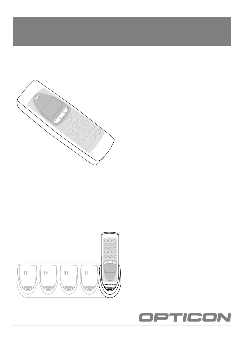
1 INTRODUCTION
The bar code data collector
The cradle
The cradle provides functionality for charging and/
or communication in several combinations. The
combinations are supported in different models:
• Charging cradle: A charging station for the bar
code data collector that charges the
rechargeable battery as soon as the bar code
data collector is placed.
• Single cradle: A regular communication and
charging station. It charges the rechargeable
battery as soon as the bar code data collector is
placed. Data will be transmitted to the host
through RS232 or USB.
The OPL972X is a range of handheld bar code
data collectors, that are well suited for a variety of
portable applications. Using a built-in laser scanner
they can read all popular types of bar code labels
at varying distances. There are several models to
meet a variety in use. All models are equipped with
data memory to collect the scanned data.
User's applications can be downloaded to the bar
code data collector to adapt it to the user's
situation. As a tool to develop an application
Opticon can supply a compiler and a development
kit.
Operating power is supplied by the rechargeable
battery. For recharging there are several cradles
available. A single cradle can charge one data
collector. A multi cradle can charge up to 5 data
collectors.
For communication the IrDA interfaced models can
communicate through a communication station. In
common the cradle supports communication for
one bar code data collector. There is also a model
available that supports communication up to 5 bar
code data collectors.
• Multicradle, single communication, multiple
charging: A multi cradle equipped with 5 slots to
keep up to 5 data collectors. One slot supports
communication, data will be transmitted to the
host through RS232 or USB. All slots charges the
rechargeable battery as soon as the bar code
data collector is placed.
• Multicradle, multiple communication, multiple
charging: A multi cradle equipped with 5 slots to
keep up to 5 data collectors, extended with
RS485 connection. All slots have the same
functionality. They charge the rechargeable
battery as soon as the bar code data collector is
placed. Data will be transmitted to the host
through RS232 or USB. The RS485 feature
enables to create a network of multicradles.
The Bluetooth model can communicate with the
SIG certified Bluetooth devices. The SPP and DUN
profile are supported.
4 - OPTICON OPL972X/CRD972X
A
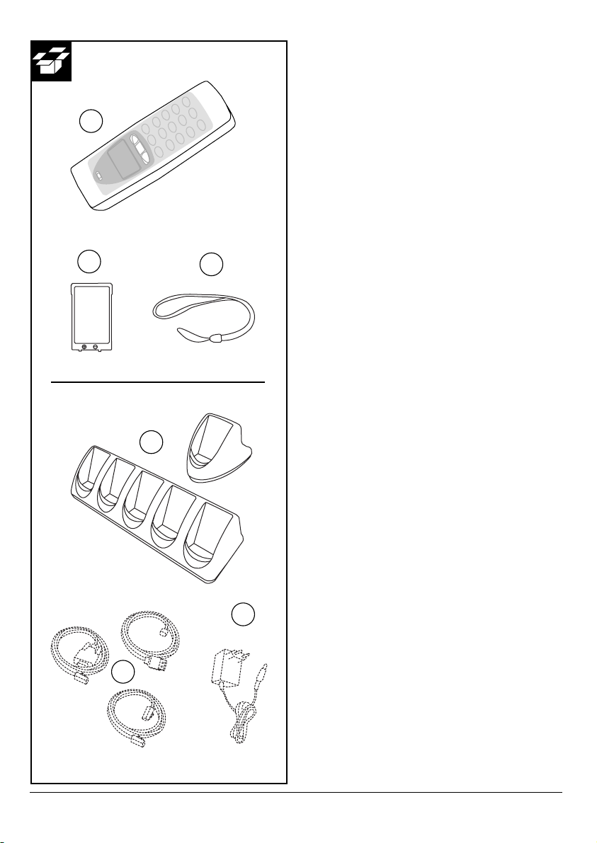
1.1 UNPACKING
When you remove the packing, please check for
any physical damage. We recommend that you
save all packing material, as it should be used
whenever you need to ship your barcode data
collector (eg. for service). Damage due to improper
repacking is not covered by the warranty.
Apart from the bar code data collector, charger or
cradle, additional items might be ordered and
supplied. If there are any missing parts please
contact your supplier.
B
C
a
OPL972X contents:
• Bar code data collector: model applicable as
supplied (A)
• Battery (B)
• Hand strap (C)
CRD972X contents:
• Cradle: model applicable as supplied (a)
CRD972X accessories
• Interface cable(s): model applicable as supplied,
can be supplied as separate item (b)
• Power supply, supplied as separate item (c)
Do not remove the product label!
On the back of every unit you will find a product
label. This is attached by the manufacturer and
includes product information and serial number. Do
not remove it.
c
b
OPL972X/CRD972X OPTICON - 5
1
1
2
3
4
5
6
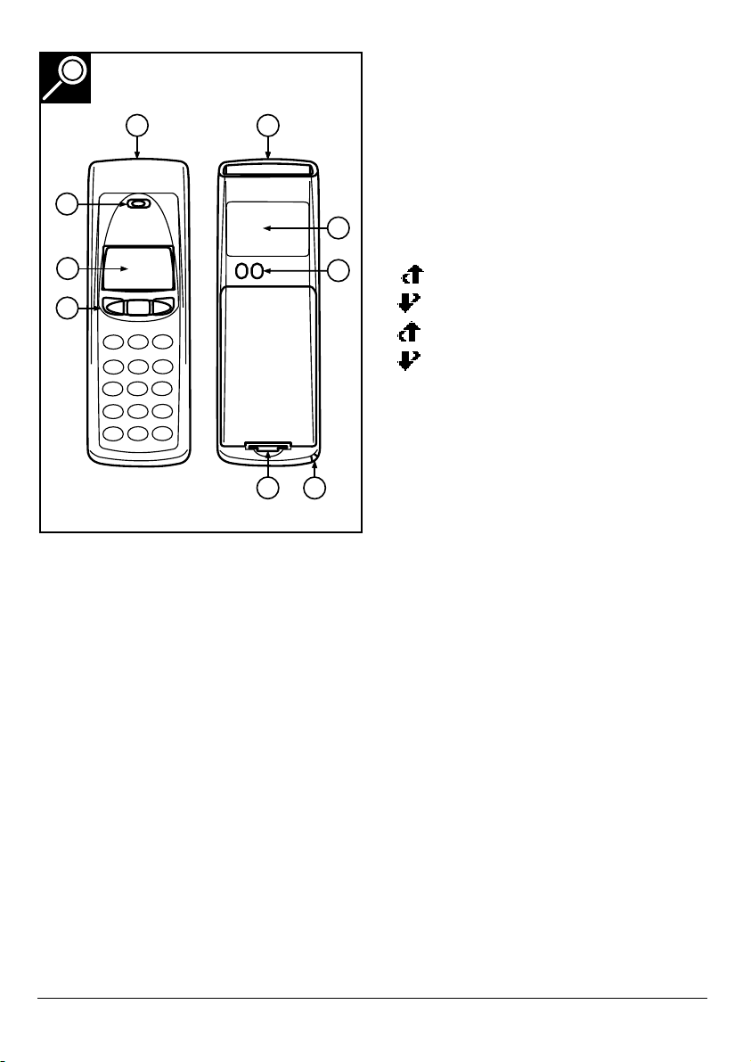
1.2 DETAILED VIEW
1.2.1 BARCODE DATA COLLECTOR DETAILS
• 1-key model:
Typical use as trigger key to switch laser beam on
for bar code reading
• other models:
Typical use of middle key as trigger key to switch
laser beam on for bar code reading.
Typical use of left and right key as menu scroll
keys or yes/no input
• keyboard:
8
7
Typical use of top middle key as trigger key to
switch laser beam on for bar code reading.
Typically basic functions for data input, as below:
: scroll up
: scroll down
+ SHIFT : scroll left
+ SHIFT: scroll right
BS : Back space
CLR : Cancel input
ENT : (Enter) to confirm input
The standard appearance of the alphanumeric
keys is the numeric value. Together with the
SHIFT key the alpha characters appear.
5. Battery case cover
For housing battery
6. Hand strap pillar
For attaching hand strap
Depending on the supplied model, the following
options are applicable:
1. Reading window / Optical window
For the emission of laser beam for bar code
reading / optical data transmission
2. Indicator
LED indicator or buzzer can be used to indicate
results, for example bar code reading / status of
communication / status of charging
3. LCD Display
For displaying information
4. Operating key(s)
Definable by application
6 - OPTICON OPL972X/CRD972X
7. Charging contacts
For power supply from cradle to bar code data
collector
8. Product label
Contains product information and serial number.
Do not remove it!
3
1
2
3 4
1
2
5
6
7
8
9
6
5
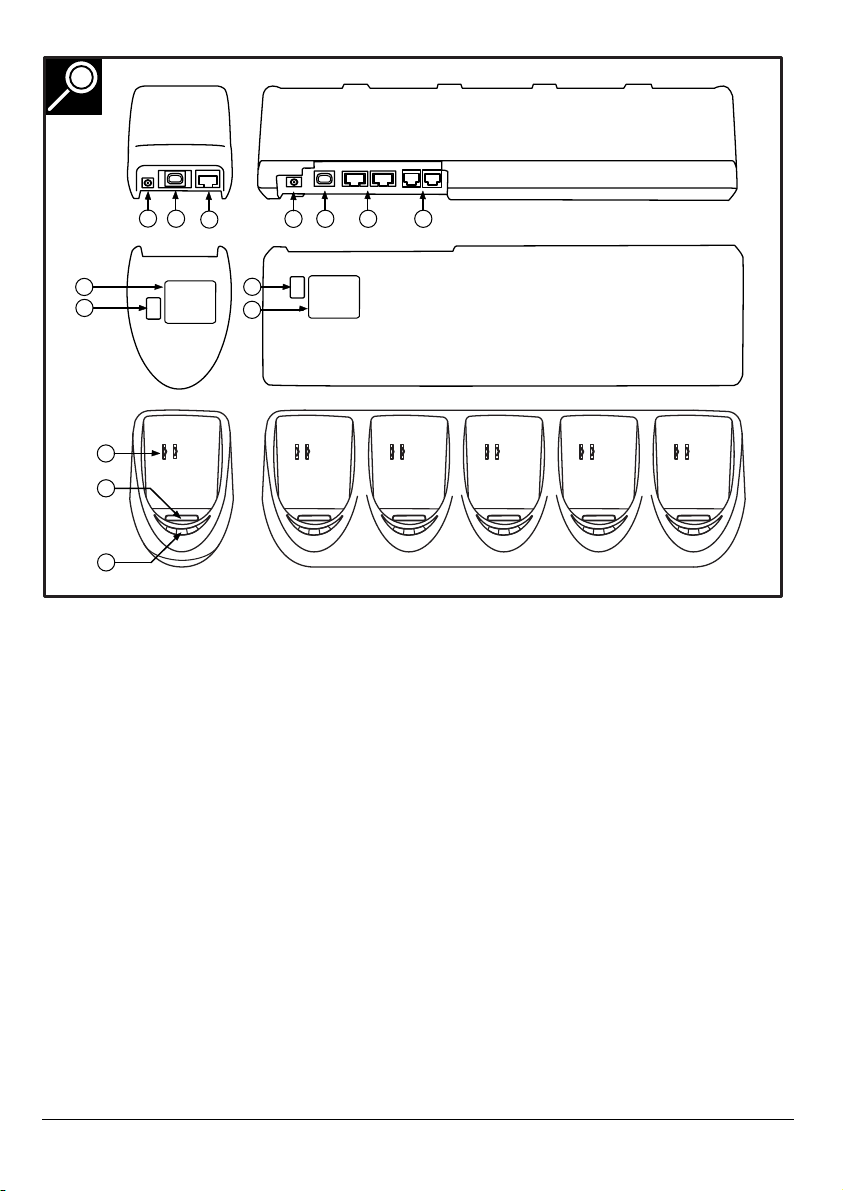
1.2.2 CRADLE DETAILS
Depending on the supplied model, the following
options are applicable:
1. DC input socket
Input for AC power supply
2. RS 232-C socket
Left connector (RS232C-1): for connection to PC
through Opticon RS232 cable
Right connector (RS232C-2): for optional
connection to second device
3. USB socket
For connecting to PC, through Opticon USB cable
4. RS 485 socket
For connection of cradle network
5. Product label
Contains product information and serial number.
Do not remove it!
6. DIP switches
Set parameters of the optical communication
interface, do not change unnecessary.
7. Electrical contacts
If the OPL972X bar code data collector is inserted
the battery will automatically be charged.
8. Optical window
Optical communication interface for data
transmission
9. LED indicator
Show current status. Read more at the installation
instructions.
OPL972X/CRD972X OPTICON - 7
 Loading...