

Page 1

Master Specification
Data Collector with Bluetooth
Model No. OPN-2002i
Manufacturing
Specification No.
XF1OPN2002 DOC_ID SS12003
Issue No. Edition 1st
Issue Date 2012-8-1
Approved by
Optoelectronics Co., Ltd.
4-12-17 Tsukagoshi Warabi-shi, Saitama
335-0002 Japan
TEL +81-48-446-1183
FAX +81-48-446-1184
営業 営業管理 C S Q A/QC 照査 作成
Page 2

OPN-2002i DOC ID:SS12003
Revision History
DOC_ID :SS12003
型 名 :OPN-2002i
Edition Date Section Description of Changes
1st 2012-8-1 -
(Initial Issue)
Page 3

OPN-2002i DOC ID:SS12003
Index page
1. ABSTRACT ................................................................................................................................. 1
OVERVIEW................................................................................................................................. 1
2.
BASIC SPECIFICATION........................................................................................................... 2
3.
DETAILED VIEW....................................................................................................................... 4
4.
5.
ELECTRICAL SPECIFICATIONS ............................................................................................ 5
5.1. USB..........................................................................................................................................5
5.2. Charging Cradle ......................................................................................................................5
6. INTERFACE ............................................................................................................................... 5
6.1. USB ..........................................................................................................................................5
6.1.1. Connector ....................................................................................................................................... 5
6.1.2.
USB Interface Circuit...................................................................................................................... 5
6.2. Bluetooth..................................................................................................................................6
6.3. Serial Interface........................................................................................................................6
6.3.1. Connector ....................................................................................................................................... 6
6.3.2.
Serial Interface Circuit .................................................................................................................... 6
7. OPTICAL SPECIFICATIONS.................................................................................................... 7
7.1. Laser Scanning Specification..................................................................................................7
7.2. Laser Scanning Specification..................................................................................................7
7.2.1. Laser Scanning Tilt......................................................................................................................... 7
7.2.2.
Scanning Curvature ....................................................................................................................... 7
8. TECHNICAL SPECIFICATIONS.............................................................................................. 7
8.1. Print Contrast Signal ..............................................................................................................8
8.2. Depth of Field and Resolution ................................................................................................8
8.3. Pitch, Skew, and Tilt ...............................................................................................................9
8.4. Curvature............................................................................................................................... 11
9. ENVIRONMENTAL SPECIFICATIONS ................................................................................ 12
9.1. Temperature ..........................................................................................................................12
9.2. Humidity................................................................................................................................12
9.3. Ambient Light Immunity...................................................................................................... 12
9.4. Dust and Drip Proof ..............................................................................................................12
9.5. Vibration Strength(without packing) ................................................................................... 13
9.6. Vibration Strength (in individual packing).......................................................................... 13
Drop Impact Strength.........................................................................................................................13
9.7. Drop Impact Strength ...........................................................................................................13
9.8. Electrical Specifications ........................................................................................................ 13
10. REGULATORY COMPLIANCE............................................................................................... 14
10.1. Laser Safety........................................................................................................................... 14
10.2. Product Safety .......................................................................................................................14
10.3. EMC .......................................................................................................................................14
10.4. Other ......................................................................................................................................15
11. ROHS......................................................................................................................................... 15
MTBF ........................................................................................................................................ 15
12.
13.
PRECAUTIONS........................................................................................................................ 15
13.1. Precaution against Laser Light ............................................................................................ 15
13.2. Handling ................................................................................................................................15
Page 4

OPN-2002i DOC ID:SS12003
13.3. Radio Low .............................................................................................................................. 16
13.4. Export Administration Regulations......................................................................................16
13.5. Bluetooth................................................................................................................................16
13.6. Frequency Band.....................................................................................................................16
14. PRODUCT LABEL ...................................................................................................................18
PACKAGING SPECIFICATIONS ........................................................................................... 19
15.
15.1. Individual Packaging Specification ......................................................................................19
15.2. Collective Packaging Specification ....................................................................................... 20
16. WARRANTY.............................................................................................................................. 21
16.1. Warranty period.....................................................................................................................21
16.2. Delivery.................................................................................................................................. 21
16.3. Repair Timeframe..................................................................................................................21
16.4. Maintenance Period...............................................................................................................21
16.5. Other ......................................................................................................................................21
17. PHYSICAL FEATURES........................................................................................................... 21
17.1. Dimensions ............................................................................................................................21
17.2. Weight .................................................................................................................................... 21
17.3. Mechanical Drawing..............................................................................................................22
18. SUPPORTED SYMBOLOGIES ............................................................................................... 23
18.1. 1D symbologies ...................................................................................................................... 23
Page 5

OPN-2002i DOC ID:SS12003
1. Abstract
This manual provides specifications for the OPN-2002i Laser Barcode Scanner.
2. Overview
The OPN-2002i scanner enables data transmission of barcode using Bluetooth wireless thechnology.
z The OPN-2002i is handy and simple data collector.
Data transmission is performed via a USB or Bluetooth.
z The OPN-2002i has SPP and HID profiles.
z Power supply is 3.7V, 230mAh(typ.) and Lithium-ion polymer battery is used.
z The power supply charging is done via a USB interface or charging cradle.
z MFi license agreement approved by Apple Inc.
1
Page 6
OPN-2002i DOC ID:SS12003
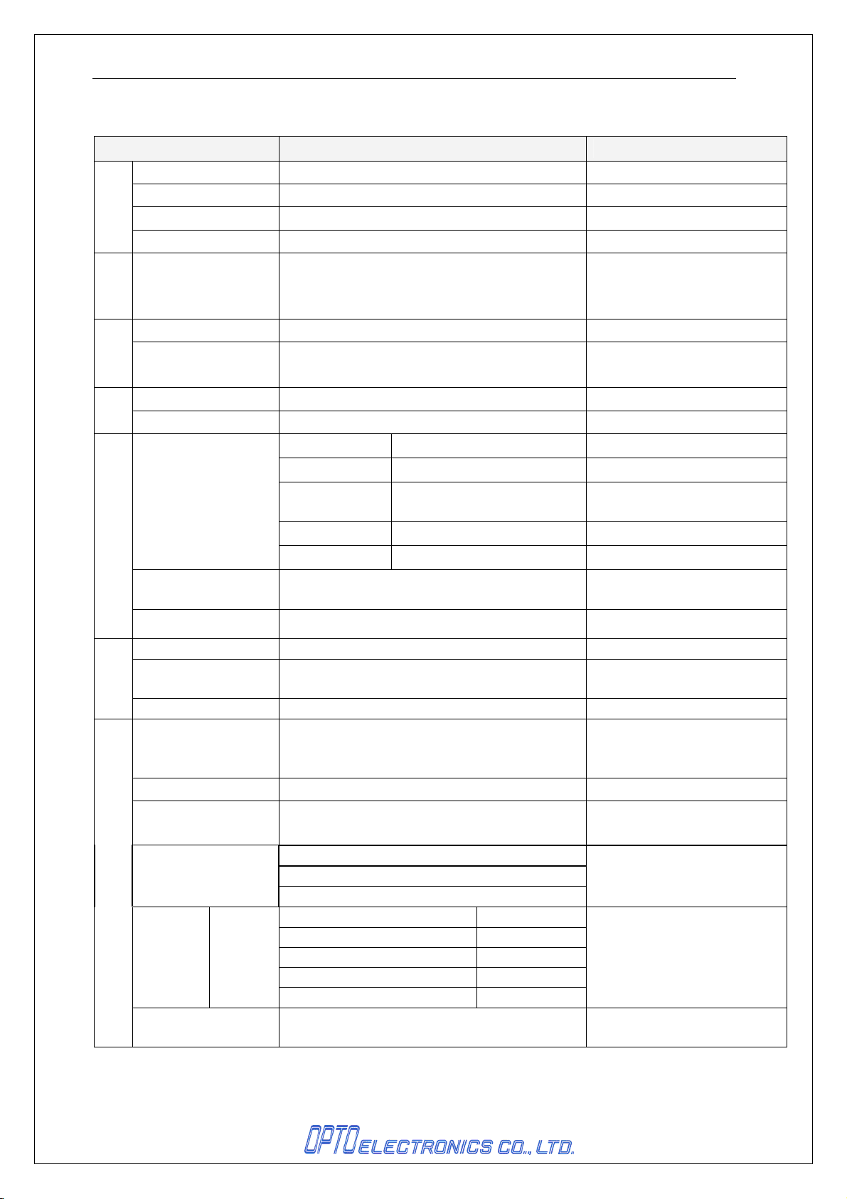
3. Basic Specification
Item Spedification Note
CPU 32bit CISC/96MHz
Section
Control
FROM 512Kbyte + 32KByte
SRAM 96Kbyte
FROM(ストレージ)
Section
Input
Key type 2 keys: Trigger, Function
Display
section
LED bi-colors(red and green) 2pcs, a blue LED
1Mbyte For user data
Beeper
RTC
Contents year, month, day, hour, minute and second
Error
Bluetooth
I /F
USB
Serial interface 2contacts for cradle.
Light emitting device Red laser diode
Section
Optical
Wave length / output
power
Scan rate
Supported
Symbologies
Minimum Resolution Code 39 : 0.127mm
Curvature
1D Symbologies
Scan Angle
DOF(mm) Code 39
Minimum PCS 0.45
Tone:variable frequency, Volume:3-level
variable
≤±90seconds per a month
Frequency
Specification Bluetooth Ver2.1
Communication
distance
Output level Class 2 4dBm max.
Profile SPP/HID
・Full-Speed 12Mbps ( HID/COM )
・Hi-Power Bus-powered 対応
650±10nm ≤1mW
100±20scan/sec
JAN,EAN,UPC-A,UPC-E,NW-7 (Codabar),
Industrial 2 of 5,Interleaved 2 of 5,
Code 11,Code 39,Code 93,Code 128 等
Radius ≥ 15mm ( 8-digiet JAN)
Radius ≥ 20mm ( 13-digit JAN)
Pitch:α≤ ±35°
Skew:β≤ ±50°(Excluding dead zone)
Tilt:γ≤ ±20°
Resolution:0.127
Resolution:0.15
Resolution:0.25
Resolution:0.5
Resolution:1.0
2402MHz ~ 2480MHz
10m
60~100
40~130
40~220
40~360
50~570
It may shorter depending on
usage environments
at 25 deg. C
Refer to Chapter18 for details
PCS 0.9
PCS 0.9
PCS 0.9
PCS 0.9
With over 70% reflectivity of
space and quiet zone.
2
Page 7
OPN-2002i DOC ID:SS12003
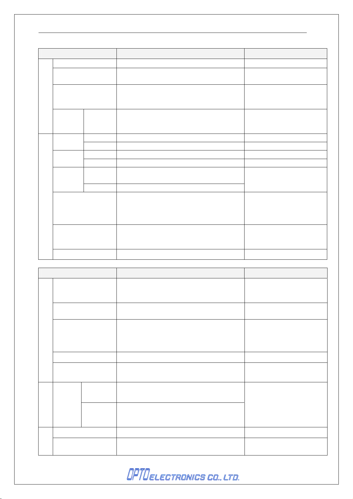
Item Specification Note
Main Battery Lithium-ion polymer battery 230mAh(typ.)
Up-time 10hours or more
Power
Range of
Operation(Charging)
4.5 ~ 5.5 V
Voltage
Current
consump
Charging <500mA
tion
Environmental Specification
ture
Humidity
Ambient
Light
Immunity
Operating
Storage
Operating
Storage
Fluorensc
ent
Sunlight:
0 ~ 50 ℃
-20 ~ 60 ℃
20%RH ~ 85%RH
20%RH ~ 85%RH
4,000 lx or less
80,000 lx or less
Increase the frequency of vibration from 10 Hz
Vibration
to 100 Hz at an accelerated velocity of 19.6
m/s2 (2G) for 6 minutes each in X, Y and
Z-direction. Repeated this test for 10 times.
Drop 3 times, at each 6 faces (right, left, front,
Drop
back and top), from a height of 120 cm onto a
concrete surface.
Dust and drip proof IP42
Item Specification Note
JIS C 6802:2011 Class2
Laser safety
IEC 60825-1 Ed.2: 2007 Class 2
CDRH Class Ⅱ
Safety standards
Regulatory
EN60950-1:2005
IEC60950-1:2006
EN55022
EMC
EN55024
FCC Part 15 Subpart C , Subpart B ClassB
VCCI ClassB
Product safety CE Marking
When a barcode is scanned
twice in 10 sec. at 25 deg. C
Tempera
No frost, no condensation.
No frost, no condensation.
For residential, commercial
and light-industrial
environments
Immunity test
Features
Physical
Other
ESD
immunit
y
Dimensions
Bluetooth logo certification
MFi License program
No
destruction
10kV (Air)
No
malfunction 8kV (Air)
62.0(D) × 32.0(W) × 17.0(H) (mm)
Condition:
IEC61000-4-6 compliant
Weight Approx. 28g Excluding the accessories
3
Page 8
OPN-2002i DOC ID:SS12003
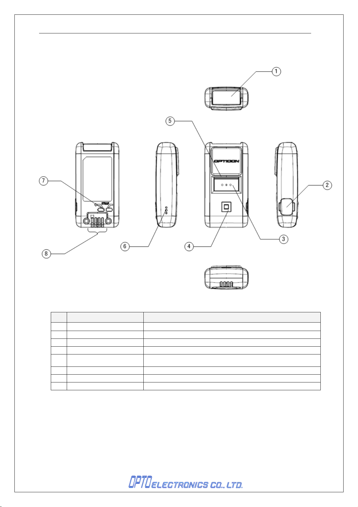
4. Detailed View
Figure 1:Detailed View
No.
Scanning Window
1
2 Scanning Window The laser light is emitted through this window.
3 Trigger Key A trigger key used to read bar codes
4 Function Key A function key that can be configured with application
5 LED
6 Buzzer Hole Sound from a built-in buzzer comes out through these holes.
7 Strap Hole A hole to attach a hand strap
8 Contact The contact is for charge and communication.
Name
Laser light is emitted through this window to read bar codes.
Indicator of operating status, such as bar code reading and
warnings
Description
4
Page 9
OPN-2002i DOC ID:SS12003
5. Electrical Specifications
5.1. USB
・Voltage : 4.5-5.5V
・Bus-Power Class : Hi-Power ( 500mA max )
・Current consumption : <500mA
5.2. Charging Cradle
・Voltage : 4.5-5.5V
6. Interface
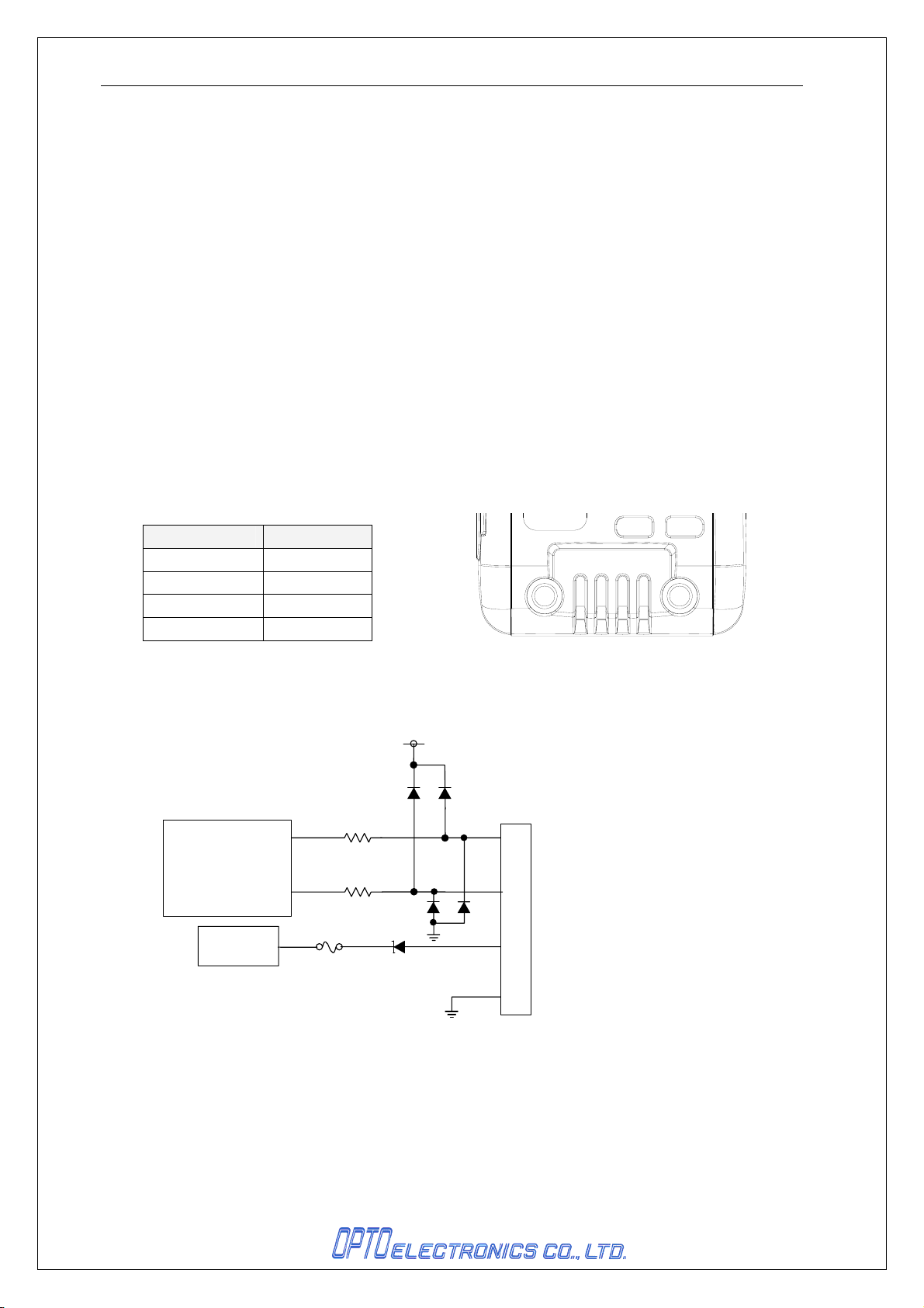
The OPN-2002i supports USB, Bluetooth and serial interfaces.
6.1. USB
This interface supported FULL Speed USB.
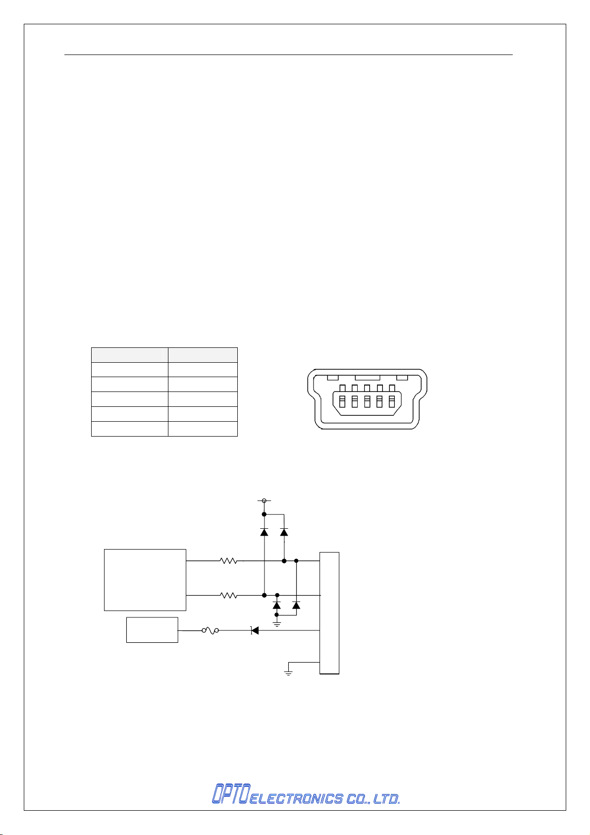
6.1.1. Connector
Signal Pin No.
VCC 1
Data(-) 2
Data(+)
( NC ) 4
GND 5
6.1.2. USB Interface Circuit
Microcontroller
+5.0V Power
3
Figure 3:USBInterface Circuit
......
1
5
......
Figure 2 : MINI USB B Connector
USB connector
3
Data(+)
Data(-)
2
VCC
1
5
4
GND
5
Page 10
OPN-2002i DOC ID:SS12003
6.2. Bluetooth
The OPN-2002i supported Bluetooth.
Frequency
Specification : Bluetooth Ver2.1
Communication
distance
Output level : Class 2 (4dBm Max.)
Supported profiles : SPP/HID
Topology of connection : Point-to-point
Operating mode : Master or Slave mode
Security mode : Enabled
Encryption : Enabled
: 2402MHz ~ 2480MHz
: 10m
6.3. Serial Interface
6.3.1. Connector
Signal Pin No.
VCC 1
RXD 2
TXD 3
GND 4
Figure 4 : Serial Interface Connector
1 2 3 4
6.3.2. Serial Interface Circuit
Microcontroller
+5.0V Power
Figure 5: Serial Interface Cirtuit
USB connector
3
TXD
RXD
2
VCC
1
4
GND
6
Page 11
OPN-2002i DOC ID:SS12003
7. Optical Specifications
7.1. Laser Scanning Specification
Item Specification Unit
Light-emitting device Red laser diode
Emission Wave length
Output power <1.0 mW
Scan Method Bi-directional
Scan Rate
Scan Angle
Angle
Effective Scan Angle 44 (min.) Deg
7.2. Laser Scanning Specification
650±10 (25 deg.C)
100±20
54±5
nm
Scan/Sec
Deg Scan
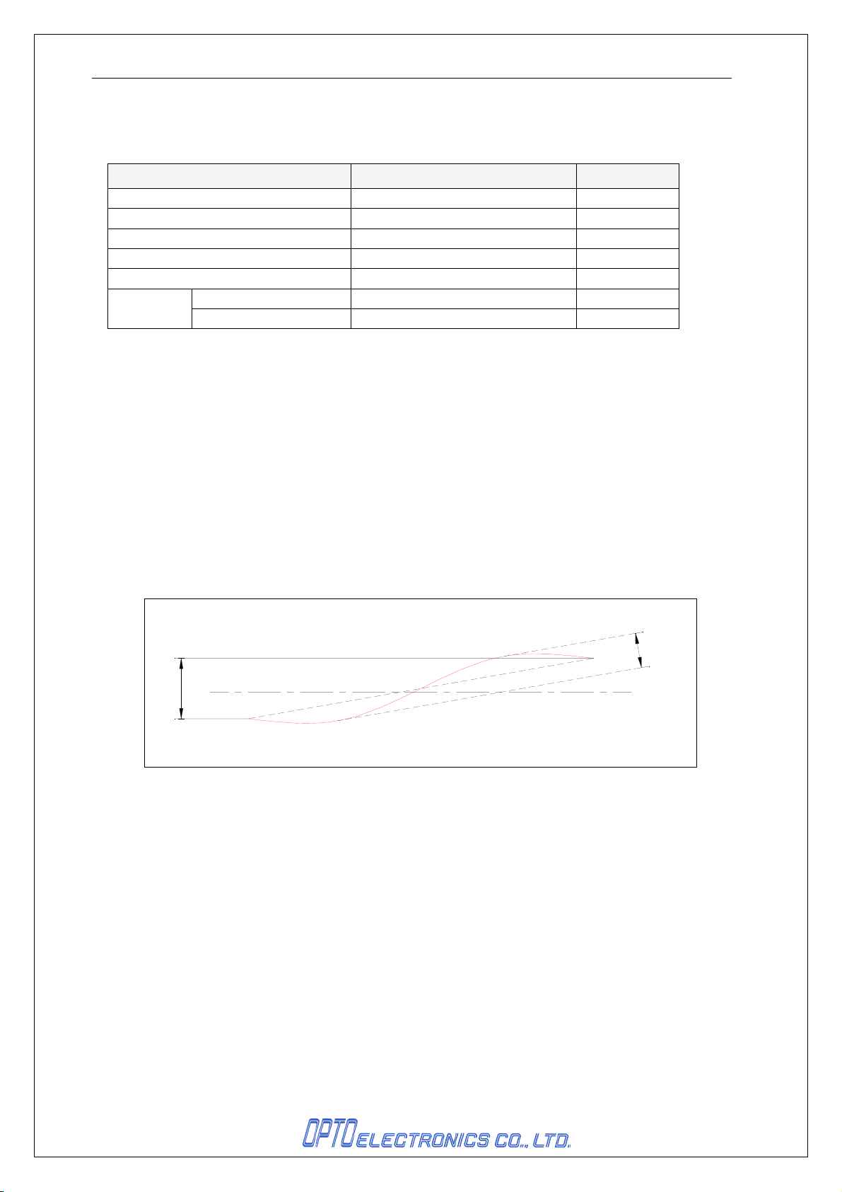
7.2.1.
Laser Scanning Tilt
Laser scanning tilt is the vertical difference between both ends of a laser scan line. Measure it in the
middle of the laser scan line.
• Up to 1.2 degrees angle in vertical direction from the scan origin (mirror motor).
• Up to 3.1 mm at 150 mm from the scan origin.
7.2.2. Scanning Curvature
The maximum difference between the laser scan line and the line between both ends of the laser
scan line. Measure it in the middle of the laser scan line.
• Up to 1.27 degrees angle in vertical direction from the scan origin (mirror motor).
• Up to 3.3 mm at 150 mm from the scan origin.
C
ur
va
t
u
r
e
ilt
T
Figure 6 : Laser Scanning Tilt and Curvature
Horizontal Line
8. Technical Specifications
The conditions for technical specifications are as follows, unless otherwise specified in each section
<Conditions>
Ambient Temperature and Humidity Room temperature, room humidity
Ambient Light 500 ~ 900 lx (excluding high-frequency lighting)
Background Black
Reading Test
Accept the performance with 10 consecutive successes
in reading. Each reading should be done in 0.5 seconds
or less.
7
Page 12
OPN-2002i DOC ID:SS12003
8.1. Print Contrast Signal
PSC 0.45 or higher (70% or higher reflectivity of space and quiet zone)
PCS =
* Be sure to keep the optical window clean without dirt or scratches, or it may have a bad effect on the
reading characteristics.
Reflectance of white bar-Reflectance of black bar
Reflectance of white bar
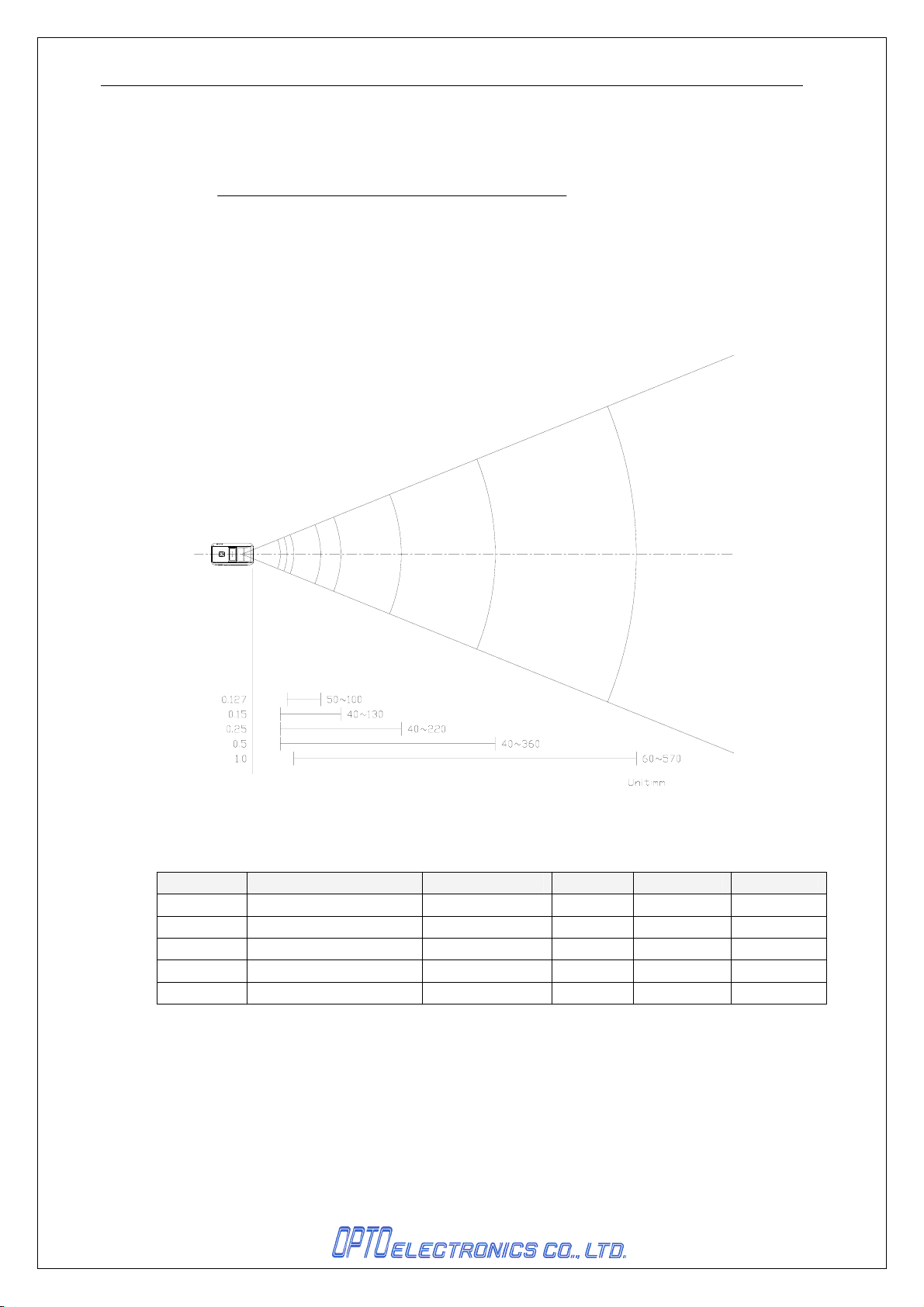
8.2. Depth of Field and Resolution
Distance in this drawing is measured from the front edge of the scanner.
Figure 7: Depth of Field
Resolution Depth of Field(mm) Symbology PCS Quiet Zone Digits
1.0mm
0.5mm
0.25mm
0.15mm
0.127mm
<Conditions>
Bar Code Sample : Optoelectronics Test Chart, N/W ratio = 1:2.5
Angle : α = 0° β = 15° γ = 0°
Curvature : R = ∞
60 ~ 570
40 ~ 360
40 ~ 220
40 ~ 130
50 ~ 100
Code 39 0.9 25mm
Code 39 0.9 18mm
Code 39 0.9 10mm
Code 39 0.9 7mm
Code 39 0.9 5mm
8
1 桁
3 桁
8 桁
10 桁
4 桁
Page 13

OPN-2002i DOC ID:SS12003
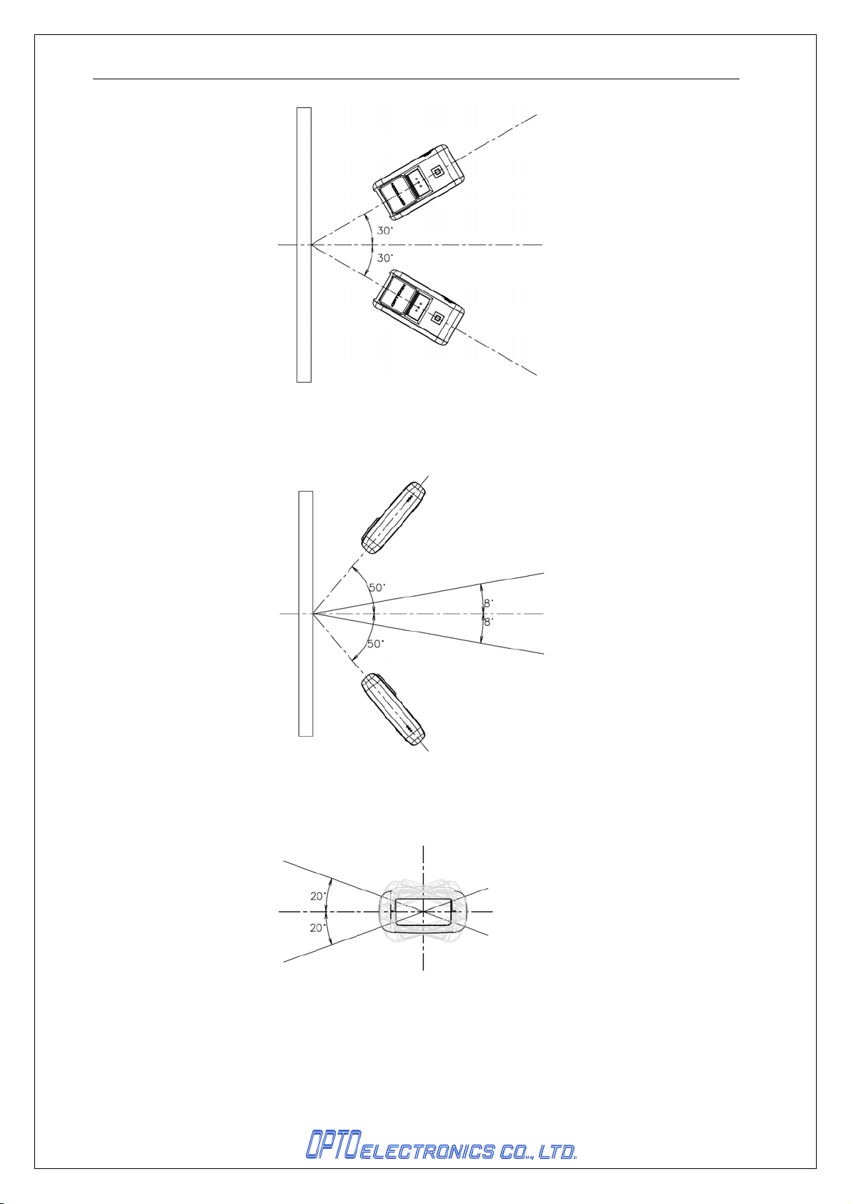
8.3. Pitch, Skew, and Tilt
Pitch : α ≦ ±30°
Skew : β ≦ ±50°
Dead Zone : β ≦ ±8 °
Tilt : γ ≦ ±20°
<Conditions>
Bar Code Sample Optoelectronics Test Sample
<Pitch, Skew and Dead Zone>
<Tilt>
Distance 100 mm from the edge of the scan engine
Angle Pitch angle : β = +15°, γ = 0°
Curvature R = ∞
(Excluding dead zone)
(Decoding may fail in some areas as a result of specular reflection)
PCS 0.9, Resolution 0.25 mm, 9-digit Code 39,
Quiet Zone 10 mm, N/W Ratio = 1 : 2.5
PCS 0.9, Resolution 0.26 mm, JAN-13, Quiet Zone 10 mm
Tilt angle : α = 0°, β = +15°
Skew angle / Dead zone: α = 0°, γ = 0°
9
Page 14
OPN-2002i DOC ID:SS12003
Figure 8: Pitch Angle
Figure 9: Skew Angle
Figure 10: Tilt Angle
10
Page 15
OPN-2002i DOC ID:SS12003
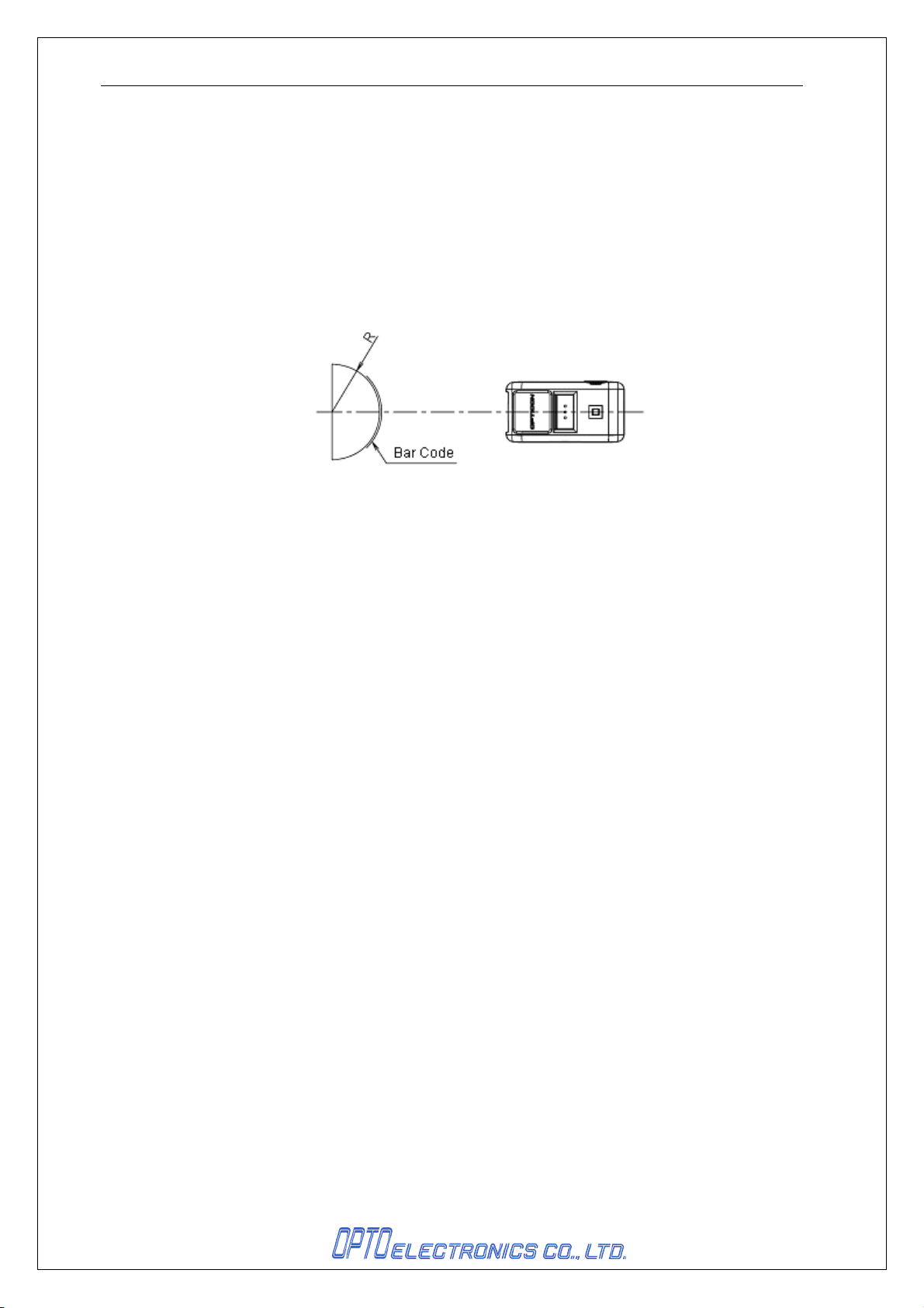
8.4. Curvature
8-digit JAN : R ≧ 15 mm
13-digit JAN : R ≧ 20 mm
<Conditions>
Bar Code Sample Optoelectronics Test Sample
PCS 0.9, Resolution 0.26 mm, JAN-13, Quiet Zone 10 mm
Distance 100 mm from the edge of the scan engine
Angle Skew angle β = +15°
Curvature R = ∞
Figure 11 : Curvature
11
Page 16

OPN-2002i DOC ID:SS12003
9. Environmental Specifications
9.1. Temperature
Operating : 0 ~ 50 ℃
Strage : -20 ~ 60 ℃
9.2. Humidity
Operating : 20 ~ 85%RH(no condensation, no frost)
Strage : 20 ~ 85%RH(no condensation, no frost)
9.3. Ambient Light Immunity
Scanning performance is guaranteed when the range of illumination on a barcode surface is the following
values.
Incandescent light : 0 ~ 4,000 lx
Fluorescent light : 0 ~ 4,000 lx
Sunlight : 0 ~ 80,000 lx
<Conditions>
Barcode Test Sample OPTOELECTRONICS test chart
Resolution 0.254 mm PDF417 specified in Chapter 7
Distance 89 mm from the front edge of the scanner.
Angles Pitch: α = 0°, Skew: β = 15°, Tilt: γ = 0°
Curvature R = ∞
Power Voltage 3.7 V
* Be sure that the direct light or specular reflection from the light source does not enter the light receiving
section of the OPN-2002i.
9.4. Dust and Drip Proof
IEC IP42 equivalent
Protection against solid objects: Level 4
Protected against solid objects greater than 1.0 mm
Protection against liquids: Level 2 (JIS IPX2)
Protected against dripping water from the vertical when tilted up to 15°
12
Page 17
OPN-2002i DOC ID:SS12003
9.5. Vibration Strength(without packing)
There shall be no sign of malfunction after the following vibration test.
Vibration test:
19.6m/s2 (2.0 G) for 30 minutes (60 minutes for a cycle) in the non-operating state. Repeat this in each X, Y
and Z direction.
Increase the frequency of the vibration from 10Hz to 100Hz at an accelerated velocity of
9.6. Vibration Strength (in individual packing)
There shall be no sign of malfunction after the following vibration test.
Vibration test:
m/s2 (2.0 G) for 30 minutes (60 minutes for a cycle) in individually packaged state. Repeat this in each X, Y
and Z direction.
Increase the frequency of the vibration from 10Hz to 100Hz at an accelerated velocity of 19.6
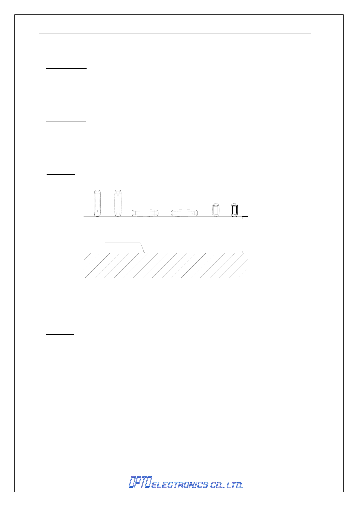
Drop Impact Strength
There shall be no sign of malfunction after the following drop test.
Drop test:
concrete floor as shown below.
Drop the scanner three times (18 times in total), at each 6 face, from a height of 120cm onto a
コンクリート
Figure 12: Drop test
9.7. Drop Impact Strength (in individual packaging)
There shall be no sign of malfunction after the following drop test.
Drop test:
from a height of 150 cm onto a concrete floor.
Drop an individually packaged scanner 10 times in total, at any of 1 corner, 3 edges, and 6 faces,
9.8. Electrical Specifications
Air discharge ±8 kV max. (No malfunction)
±10 kV max. (No destruction)
Measurement environment An electrostatic testing device compliant with IEC 61000-4-2 is
used.
Discharge resistance 330 Ω
Charging capacitor 150 pF
120cm
13
Page 18

OPN-2002i DOC ID:SS12003
10. Regulatory Compliance
10.1. Laser Safety
JIS C 6802:2011 Class 2
IEC 60825-1 Ed.2: 2007 Class 2
CDRH Class Ⅱ
10.2. Product Safety
EN60950-1:2005
IEC60950-1:2006
10.3. EMC
EN55022
EN55024
FCC Part 15 Subpart C , Subpart B ClassB
Federal Communications Commission Notices
This product complies with Part 15 of the FCC Rules. Operation is subject to the
following two conditions:
(1) this device may not cause harmful interference, and
(2) this device must accept any interference received, including interference that may
cause undesired operation.
Harmful Interference Notice
This product has been tested and complies with the specifications for a Class B digital
device, pursuant to Part 15 of the FCC Rules. These limits are designed to provide
reasonable protection against harmful interference in a residential installation. This
equipment generates, uses, and can radiate radio frequency energy and, if not installed
and used according to the instructions, may cause harmful interference to radio
communications. However, there is no guarantee that interference will not occur in a
particular installation. If this equipment does cause harmful interference to radio or
television reception, which is found by turning the equipment off and on, the user is
encouraged to try to correct the interference by one or more of the following measures:
• Reorient or relocate the receiving antenna
• Increase the separation between the equipment or devices
• Connect the equipment to an outlet other than the receiver's
• Consult a dealer or an experienced radio/TV technician for assistance
Changes or modifications to this equipment that have not been approved by Ruckus
Wireless may void the user's authority to operate this equipment.
RF Exposure
The OPN-2002n unit (FCC ID: UFOOPN2002
limits set
Exposure Guidelines in Supplement C to OET65. The unit has very low level of RF
energy that it is deemed to comply without testing of specific absorption ratio (SAR).
forth for uncontrolled environment and meets the FCC radio frequency (RF)
complies with FCC radiation exposure
I)
14
Page 19
OPN-2002i DOC ID:SS12003
VCCI Class B
This is a Class B product, to be used in a domestic environment, based on the Technical
Requirement of the Voluntary Control Council for Interference from Information
Technology Equipment (VCCI). If this is used near a radio or television receiver in a
domestic environment, it may cause radio interference.
10.4. Other
Bluetooth logo certification
MFi License Program
The OPN-2002i uses Bluetooth module which qualifies as radio equipment for low-power radio
stations as specified in the Radio Law 38-24-1.
Specified Radio Equipment:
Low power data communications system in the 2.4GHz band in Article 2 paragraph 1 item (19),
Ordinance of MPT.
Model type of Bluetooth module:OPA-26X1
Number of certification:
201-125603
11. RoHS
The OPN-2002i is compliant with RoHS.
RoHS: The restriction of the use of certain hazardous substances in electrical and electronic
equipment, 2002/95/EC
12. MTBF
MTBF (Mean Time Between Failures) 10,000 hours
13. Precautions
13.1. Precaution against Laser Light
*Use of controls or adjustments or performance of procedures other than those specified herein may result
in hazardous radiation exposure.
Caution - Do not stare into the laser light from a scanning window. It may harm your eyes.
Do not point the laser directly at others’ eyes. It may harm your eyes.
Do not stare into the beam with optical instruments. It may harm your eyes.
13.2. Handling
Handle this product carefully. Do not deliberately subject it to any of the following:
(1) Shock:
• Do not drop this product from a height greater than specified in this manual.
• Do not place this product under or between any heavy items.
• Do not swing this product around holding the hand strap.
(2) Temperature Conditions:
• Do not use this product at temperatures outside the specified range.
• Do not pour boiling water on this product.
• Do not throw this product into a fire.
(3) Foreign Materials:
15
Page 20

OPN-2002i DOC ID:SS12003
• Do not immerse this product in water or other liquid.
• Do not expose this product to chemicals.
(4) Others
• Do not disassemble this product.
• Do not use this product near a radio or a TV. It may cause reception problems.
• This product may be affected by a momentary voltage drop caused by lightning.
• This product may not perform properly in a place where it will be subjected to a flickering light, such as a
CRT (computer monitor, television, etc.).
13.3. Radio Low
The OPN-2002i uses Bluetooth module which qualifies as radio equipment for low-power radio stations (2.4
GHz band advanced data communication systems) as specified in the Radio Law 38-24-1.
Therefore it does not need to have a radio station license in Japan.
The following activities are prohibited under the Radio Law:
・ Remodeling and disassembly
・ Peeling off the certificate label
Do NOT use the scanner under the following environment, as radio interference may affect other device and
end up with causing physical or material damage.
・ Safety apparatus and medical device for human body protection
・ Environment where is concerned to cause serious damage
13.4. Export Administration Regulations
This product is subject to the strategically controlled exports regulated under “Foreign Exchange and
Foreign Trade Laws”. Therefore, export of this product may require an export permission of Japanese
government.
13.5. Bluetooth
To communicate via Bluetooth, the device which OPN-2002i is connected to must support the same
Bluetooth version and profile as OPN-2002i’s.
・ OPN-2002i is compliant to Bluetooth standards. However, we cannot assure the connection between
OPN-2002i and other Bluetooth devices which have not been tested.
・ Bluetooth supporting devices use 2.4 GHz frequency band. However, many other sorts of devices also
utilize this frequency band. It may have an effect on the communication speed or communication range of
this data collector.
・ The use of OPN-2002i outside of the European Union, the United States and Canada is punishable under
the law.
・ Communication speed and communication range of OPN-2002i may differ due to the obstacles and radio
wave conditions between OPN-2002i and the device, which OPN-2002i is connected to.
・ Conditions of the device, which OPN-2002i is connected to, may also affect the communication speed and
communication range of OPN-2002i.
13.6. Frequency Band
The frequency band 2.4 GHz is utilized by this product. Read carefully the followings before using this
product.
In the frequency band of this product, scientific, medical and industrial devices including microwaves are
used. Also other radio stations including local private radio station for mobile object identification requiring
16
Page 21

OPN-2002i DOC ID:SS12003
license for such as manufacturing lines at factories, specific power-saving radio station requiring no license
and amateur radio station are managed.
1. Please make sure that “other radio stations” are not managed in the frequency band 2.4 GHz before
using this product.
2. In case that radio interference occurs between this product and “other radio stations,” change the
service space immediately, or stop transmitting radio wave to avoid the interference.
3. If you have any questions or troubles, please contact our sales office.
* This specification manual is subject to change without prior notice.
17
Page 22
OPN-2002i DOC ID:SS12003
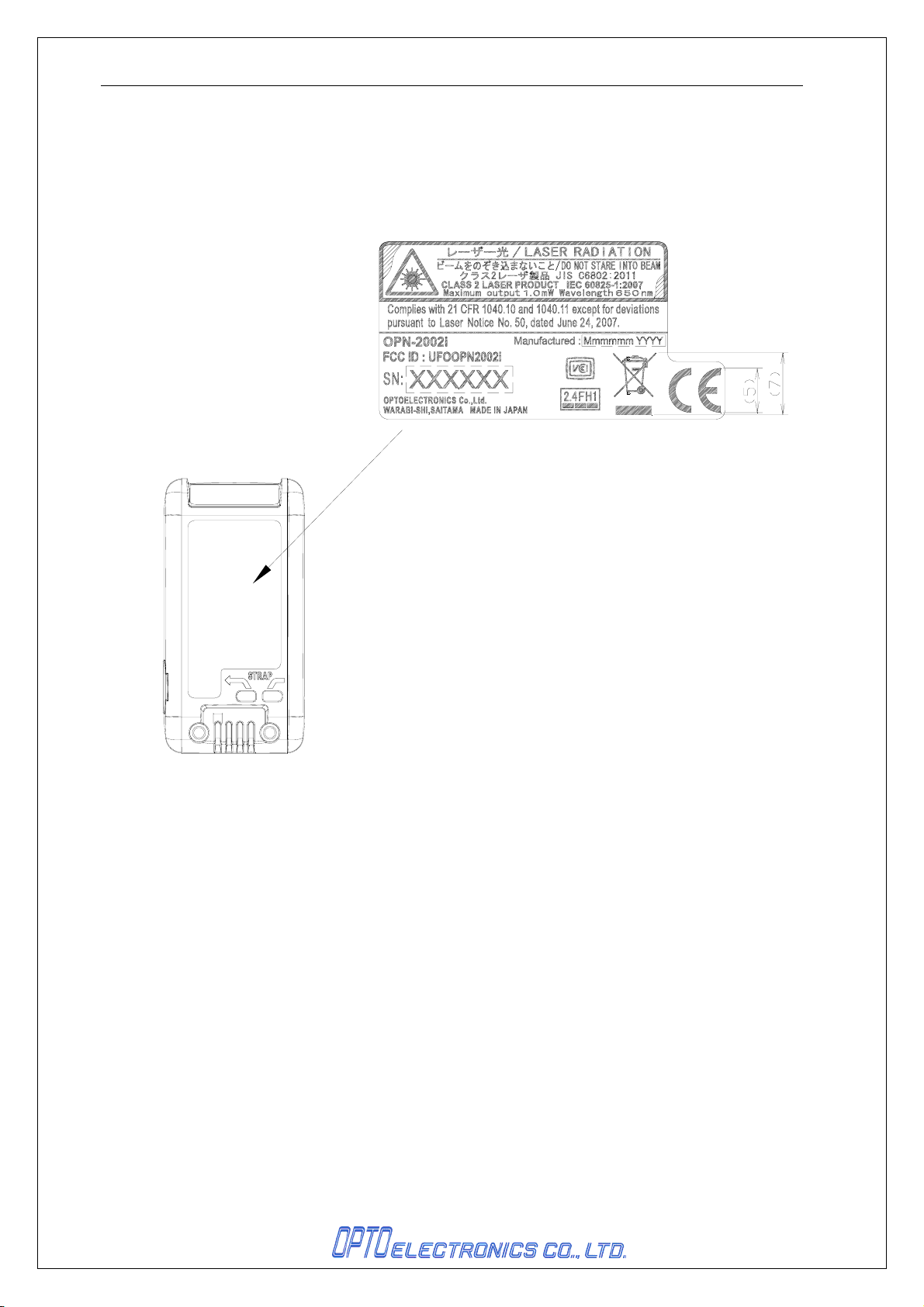
14. Product Label
The labels shown below are attached to the back side of the data collector.
Figure 13:
Product & Laser Caution Label
18
Page 23
OPN-2002i DOC ID:SS12003
15. Packaging Specifications
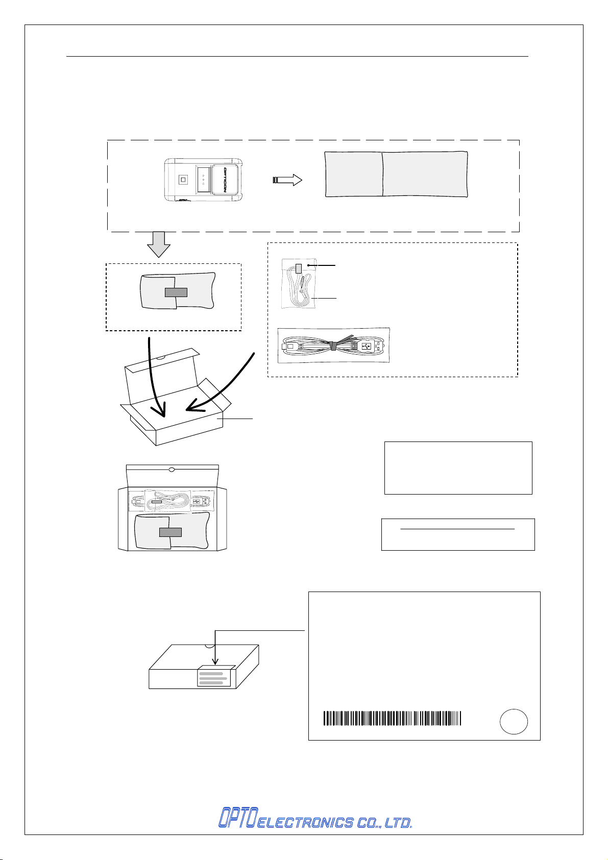
15.1. Individual Packaging Specification
Assembled package size: 125 x 112 x 40 (WDH mm)
AIR PACKING
OPN10018003-0-01
Poly bag
No.3(0.03×80×150)
Neck strap
OPN10019106-0-02
テープで止める
Mini USB cable(ベージュ)
G9904B099-002
*折り目にバーコードがかからない事
BOX
No.OPN20018001-0-00
【国内向】 個装箱バーコードラベル (3A0002)
Model No.
OPN-2002i-BLK
Spec No.
*バーコード*
*XF5OPN2002*
Item No.
*-*
Serial No.
123456=製 品シリアルNo.
中国生産(produced in China)=MADE IN CHINA
日本生産(produced in Japan)=MADE IN JAPAN
MODEL NEME
シリアルNo.の表示 に ついて
『 123456 』
6桁のシリアルNo.を表示
【原産国表示】~country of origin~
MADE IN
▲▲▲▲▲
Quantity 1
*△△△△△△*
Ro
Figure 14:
Individual Packaging
19
Page 24
OPN-2002i DOC ID:SS12003
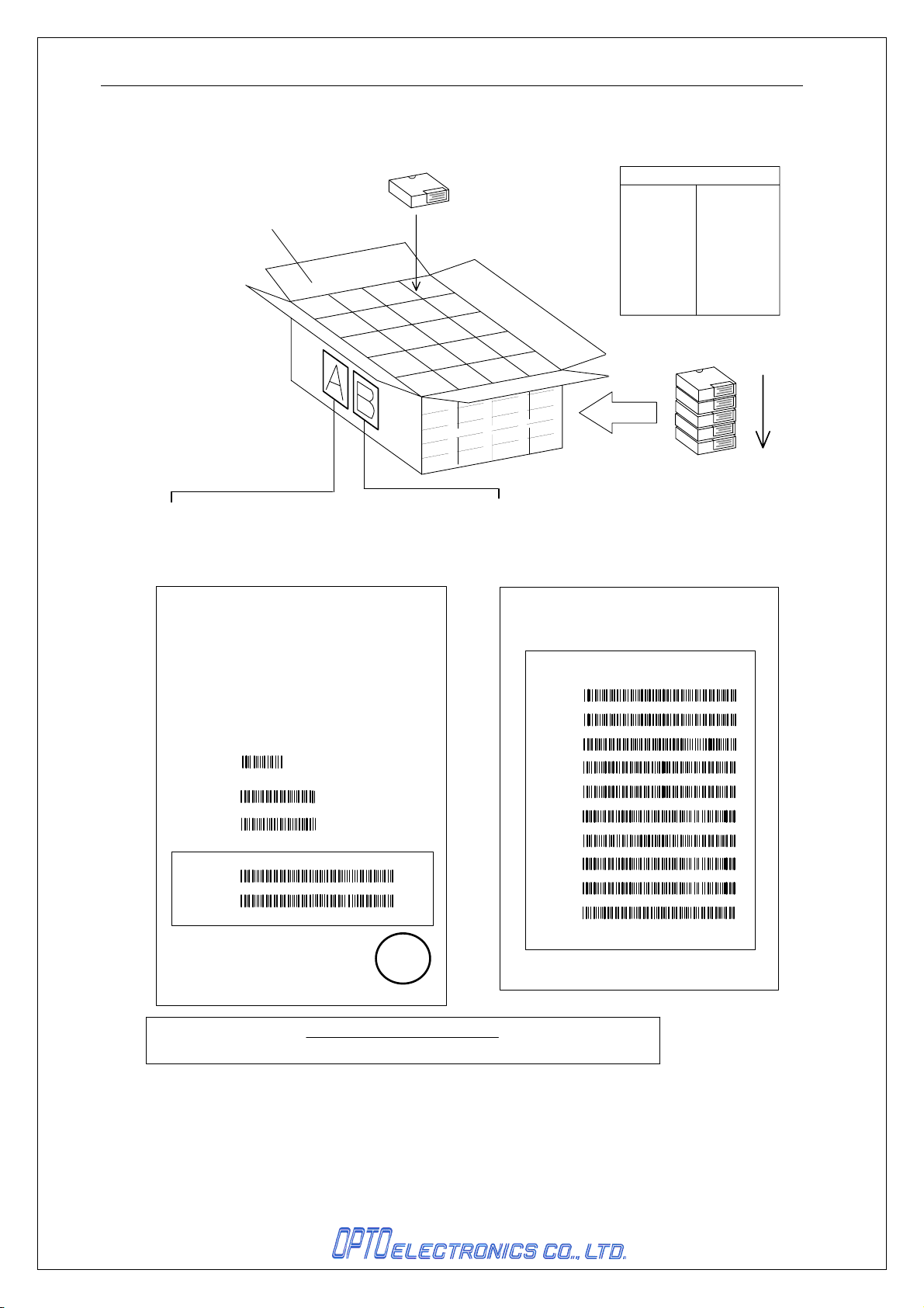
15.2. Collective Packaging Specification
Assembled package size: 595 x 520 x 245 (WDH mm), 100 pieces/box
シリアルNo.の順序
⑪51~55
⑫56~60
⑬61~65
⑭66~70
⑮71~75
⑯76~80
⑰81~85
⑱86~90
⑲91~95
⑳96~100
Carton Box(5B0008)100台入り
⑯
⑰
⑪
⑱
⑫
⑥
⑲
⑬
⑦
①
⑳
⑭
⑧
②
⑮
⑨
③
⑩
④
⑤
5段入り
①1~5
②6~10
③11~15
④16~20
⑤21~25
⑥26~30
⑦31~35
⑧36~40
⑨41~45
⑩46~50
A :【国内向】 外装箱バーコードラベル
正面と背面の2ヶ所に貼付(面の中央付近)
(3C0006)
C/No.
MADE IN
Product
PO#
Spec#
Item# バーコード
Q'ty
S/N(from)
S/N(to)
ROM-Ver.(MAIN)
ROM-Ver.(Bluetooht)
Shipping Date
OPN-2002i-BLK
△△△△-△△
*
*
*XF5OPN2002*
*△△*
*000001*
▲▲▲
*000
Missing Serial Number Missing Q'ty △
1
2
△△△△△△
*
△△△△△△
*
TC01J**
TD01J**
20△△/△△/△△
△△/△△
*
*
*
OPTOELECTRONICS CO.,LTD.
△△
▲▲▲▲▲
Ro
B:【国内向】 Missing Serial Numberラベル
欠品が3つ以上の場合にのみ貼付する
Aラベルと並べ正面と背面の2ヶ所に貼付(面の中央付近)
(3C0007)
C/No.
△△
▲▲▲▲▲
MADE IN
Missing Serial Number Missing Q'ty △△
3
△△△△△△
4
5
6
7
8
9
10
11
12
*
△△△△△△
*
△△△△△△
*
△△△△△△
*
△△△△△△
*
△△△△△△
*
△△△△△△
*
△△△△△△
*
△△△△△△
*
△△△△△△
*
OPTOELECTRONICS CO.,LTD.
*
*
*
*
*
*
*
*
*
*
【原産国表示】~country of origin~
中国生産(produced in China)=MADE IN CHINA 日本生産(produced in Japan)=MADE IN JAPAN
Figure 15:
Collective Packaging
20
Page 25

OPN-2002i DOC ID:SS12003
16. Warranty
16.1. Warranty period
OPTOELECTRONICS Co., Ltd. warrants that this product is free of defects or malfunctions for a
period of twelve (12) months from its shipment. In case of having defects or malfunctions caused by
normal usage in accordance with this specification during the foregoing warranty period,
OPTOELECTRONICS shall repair or adjust the product free of charge.
Any repair or replacement of the product after the foregoing warranty period shall be charged at
regular repair rates.
If defects or malfunctions were caused by customer mishandling, product repairs or replacement will
be charged at regular repair rates, even during the foregoing warranty period.
16.2. Delivery
Products for maintenance or repair shall be sent back to OPTOELECTRONICS. The sender is
responsible for all shipping costs.
16.3. Repair Timeframe
Repaired products shall be shipped back to the customer within 20 days after acceptance by
OPTOELECTRONICS.
Expedited repairs may be available, subject to terms agreed to by OPTOELECTRONICS and the
customer.
16.4. Maintenance Period
The maintenance period of this product is 5 years after its shipment.
OPTOELECTRONICS may discontinue maintenance for this product during the 5-year maintenance
period if a satisfactory replacement product or maintenance solution is agreed to.
16.5. Other
Any additional warranty issues must be discussed with OPTOELECTRONICS on a case-by-case
basis.
17. Physical Features
17.1. Dimensions
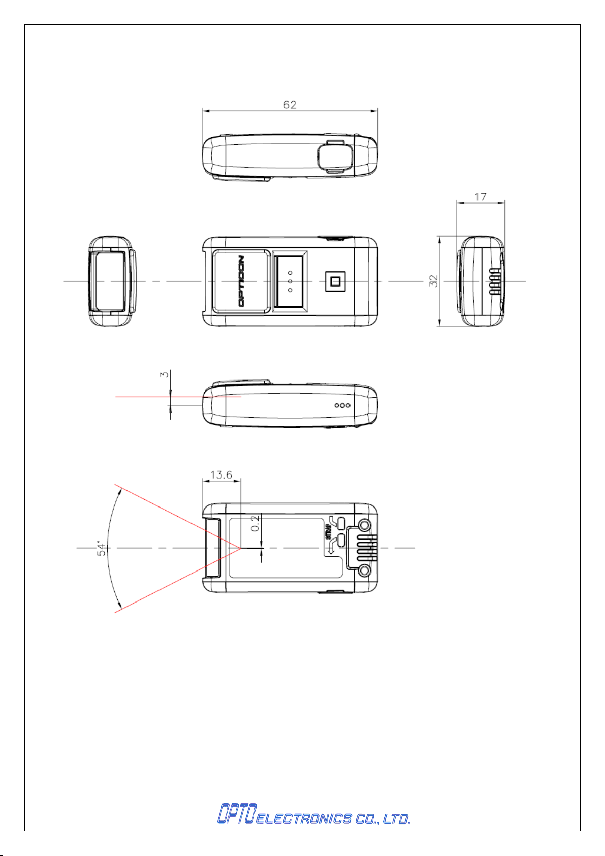
62.0(D) × 32.0(W) × 17.0(H) (mm)
17.2. Weight
Approx. 28g (Excluding the accessories)
21
Page 26
OPN-2002i DOC ID:SS12003
17.3.
Mechanical Drawing
Figure 16:
Mechanical Drawing
22
Page 27

OPN-2002i DOC ID:SS12003
18. Supported Symbologies
18.1. 1D symbologies
Symbology Symbology
JAN13 digits Interleaved 2 of 5
JAN13 digits + ADDON2 digits Code 93
JAN13 digits + ADDON5 digits Code 128
JAN8 digits MSI/Plessey
JAN8 digits + ADDON2 digits IATA
JAN8 digits + ADDON5 digits UK/Plessey
EAN13 digits Telepen
EAN13 digits + ADDON2 digits Matrix 2 of 5
EAN13 digits + ADDON5 digits ChinesePostMatrix 2 of 5
EAN8 digits NW-7 ABC Code
EAN8 digits + ADDON2 digits NW-7 CX Code
EAN8 digits + ADDON5 digits S-Code
Instore Code 13 digits Tri/Optic
Instore Code 8 digits Code 39 Full Ascii
UPC-A Code 39 It.Pharmaceutical
UPC-A+ADDON2 digits EAN 128
UPC-A+ADDON5 digits RSS-14
UPC-E RSS Limited
UPC-E+ADDON2 digits RSS Expanded
UPC-E+ADDON5 digits PDF417
UPC-E1 MicroPDF417
UPC-E1+ADDON2 digits Code 11
UPC-E1+ADDON5 digits Korean Post
Code 39
NW-7 (Codabar)
Industrial 2 of 5
23
 Loading...