

Page 1

Wireless Handheld 2D Scanner
OPI-3301
Tentative
This manual provides specifications for the OPI-3301
rugged handheld 1D/2D imager scanner with autofocus.
Specifications Manual
Page 2

All information subject to change without notice.
Document History
OPI-3301
Specifications Manual
Model Number:
Edition:
Date:
OPI-3301
1st
2011-05-XX
Specification Number:
Original Spec Number:
SS11012
SS10037
Copyright 2010 Opticon. All rights reserved.
This manual may not, in whole or in part, be copied, photocopied, reproduced, translated or converted to any
electronic or machine readable form without prior written consent of Opticon.
Limited Warranty and Disclaimers
PLEASE READ THIS MANUAL CAREFULLY BEFORE INSTALLING OR USING THE
PRODUCT.
Serial Number
A serial number appears on all Opticon products. This official registration number is directly related to the device
purchased. Do not remove the serial number from your Opticon device. Removing the serial number voids the
warranty.
Warranty
Unless otherwise agreed in a written contract, all Opticon products are warranted against defects in materials and
workmanship for two years after purchase. Opticon will repair or, at its option, replace products that are defective
in materials or workmanship with proper use during the warranty period. Opticon is not liable for damages caused
by modifications made by a customer. In such cases, standard repair charges will apply. If a product is returned
under warranty and no defect is found, standard repair charges will apply. Opticon assumes no liability for any
direct, indirect, consequential or incidental damages arising out of use or inability to use both the hardware and
software, even if Opticon has been informed about the possibility of such damages.
Packaging
The packing materials are recyclable. We recommend that you save all packing material to use should you need
to transport your scanner or send it for service. Damage caused by improper packaging during shipment is not
covered by the warranty.
Trademarks
Trademarks used are the property of their respective owners.
Opticon Inc. and Opticon Sensors Europe B.V. are wholly owned subsidiaries of OPTOELECTRONICS Co., Ltd.,
12-17, Tsukagoshi 4-chome, Warabi-shi, Saitama, Japan 335-0002. TEL +81-(0) 48-446-1183; FAX +81-(0) 48446-1184
SUPPORT
USA Europe
Web: www.opticon.com
2
Page 3

Specifications Manual
Revision History
Specification No. : SS11012
Product name : OPI-3301
Edition Date Page Section Description of Changes
First 2011/05/xx - - Initial release
OPI-3301
3
Page 4

OPI-3301
Specifications Manual
Contents
1. Abstract..........................................................................................................................................................6
2. Overview......................................................................................................................................................... 6
3. Basic Specifications...................................................................................................................................... 7
4. Detailed View ............................................................................................................................................... 10
4.1. Status LED and Buzzer........................................................................................................................ 11
5. Electrical Specifications............................................................................................................................. 12
5.1. Configuration........................................................................................................................................ 12
5.2. Current Consumption........................................................................................................................... 12
5.3. Charging Current ................................................................................................................................. 12
5.4. Operating and Charging Time.............................................................................................................. 13
6. Optical Specifications................................................................................................................................. 13
7. Technical Specifications.............................................................................................................................14
7.1. Scan Area and Depth of Field.............................................................................................................. 15
7.2. Printed Contrast Signal (PCS) ............................................................................................................. 16
7.3. Minimum Resolution ............................................................................................................................ 16
7.4. Pitch, Skew and Tilt ............................................................................................................................. 16
7.5. Curvature ............................................................................................................................................. 17
8. Bluetooth......................................................................................................................................................18
9. Default Settings........................................................................................................................................... 19
10. Product Labels........................................................................................................................................... 22
11. Packaging Specifications......................................................................................................................... 24
11.1. Individual Packaging Specification .................................................................................................... 24
11.2. Collective Packaging Specification .................................................................................................... 25
12. Environmental Specifications.................................................................................................................. 26
12.1. Operating Temperature and Humidity ............................................................................................... 26
12.2. Storage Temperature and Humidity................................................................................................... 26
12.3. Ambient Light Immunity ..................................................................................................................... 26
12.4. Dust and Drip Proof ......................................................................................................
..................... 27
12.5. Electrical Characteristics.................................................................................................................... 27
12.6. Drop Impact Strength (without packaging) ........................................................................................ 27
12.7. Drop Impact Strength (in individual packaging) ................................................................................. 27
12.8. Vibration Strength .............................................................................................................................. 28
13. Reliability.................................................................................................................................................... 28
14. Regulatory Compliance ............................................................................................................................ 28
14.1. LED Safety........................................................................................................................................ 28
14.2. Laser Safety...................................................................................................................................... 28
14.3. Product Safety .................................................................................................................................. 28
14.4. EMC.................................................................................................................................................. 28
4
Page 5

OPI-3301
Specifications Manual
14.5. Others ............................................................................................................................................... 28
15. RoHS........................................................................................................................................................... 28
16. Precautions................................................................................................................................................ 29
16.1. Precaution against Laser Light .......................................................................................................... 29
16.2. Precaution against LED Light ............................................................................................................ 29
16.3. Handling............................................................................................................................................. 29
16.4. Radio Low .......................................................................................................................................... 29
16.5. Export Administration Regulations..................................................................................................... 30
16.6. Bluetooth............................................................................................................................................ 30
16.7. Frequency Baud................................................................................................................................. 30
17. Auto Trigger............................................................................................................................................... 31
17.1. Outline of Operation........................................................................................................................... 31
17.2. Specifications..................................................................................................................................... 31
Appendix 1: Mechanical Drawings................................................................................................................ 33
5
Page 6

Specifications Manual
1. Abstract
This manual provides specifications for the OPI-3301 rugged wireless handheld 1D/2D imager
scanner.
2. Overview
The OPI-3301 scanner enables data transmission of linier (1D) and 2D symbologies using
Bluetooth wireless technology. Main features of the OPI-3301 are as follows:
・High-speed scanning
A custom high-speed / high-sensitive CMOS image sensor with a maximum frame rate of 80 fps
and the fastest shutter speed in the industry enable high speed scanning without being affected
by hand movement.
・Auto-focus
Focus adjustment function using liquid lens enables reading of high resolution codes and long
depth of field.
・Antimicrobial coating
Special antimicrobial treatment is applied to chassis, and alcohol can be used to wipe the
scanner clean (except for the scanning window).
・Bluetooth interface
The specification of transmission output Class 2 enables communication range of approximately
10 meters.
・Full charge in 3 hours with a dedicated cradle
A communication cradle CRD-3301 with charging function can fully charge the OPI-3301 in 3
hours (it takes 6 hours with USB bus power).
・Wide range of supported symbologies
1D bar codes: WPC (EAN, JAN, UPC-A/UPC-E), Industrial 2 of 5, IATA, Interleaved 2 of 5,
Codabar (NW-7), Code 39, Code 93, Code 128, MSI/Plessey, RSS cods are supported.
2D codes: PDF417, MicroPDF417, QR Code, Micro QR Code, DataMatrix (ECC 0 - 140 / ECC
200), MaxiCode (Modes 0 ~ 5), Aztec Code , Composite codes are supported.
For details, refer to Chapter 9 “Default Settings”
・RoHS compliance
The OPI-3301 is a RoHS compliant product, which is declared by Optoelectronics Co., Ltd.
OPI-3301
6
Page 7

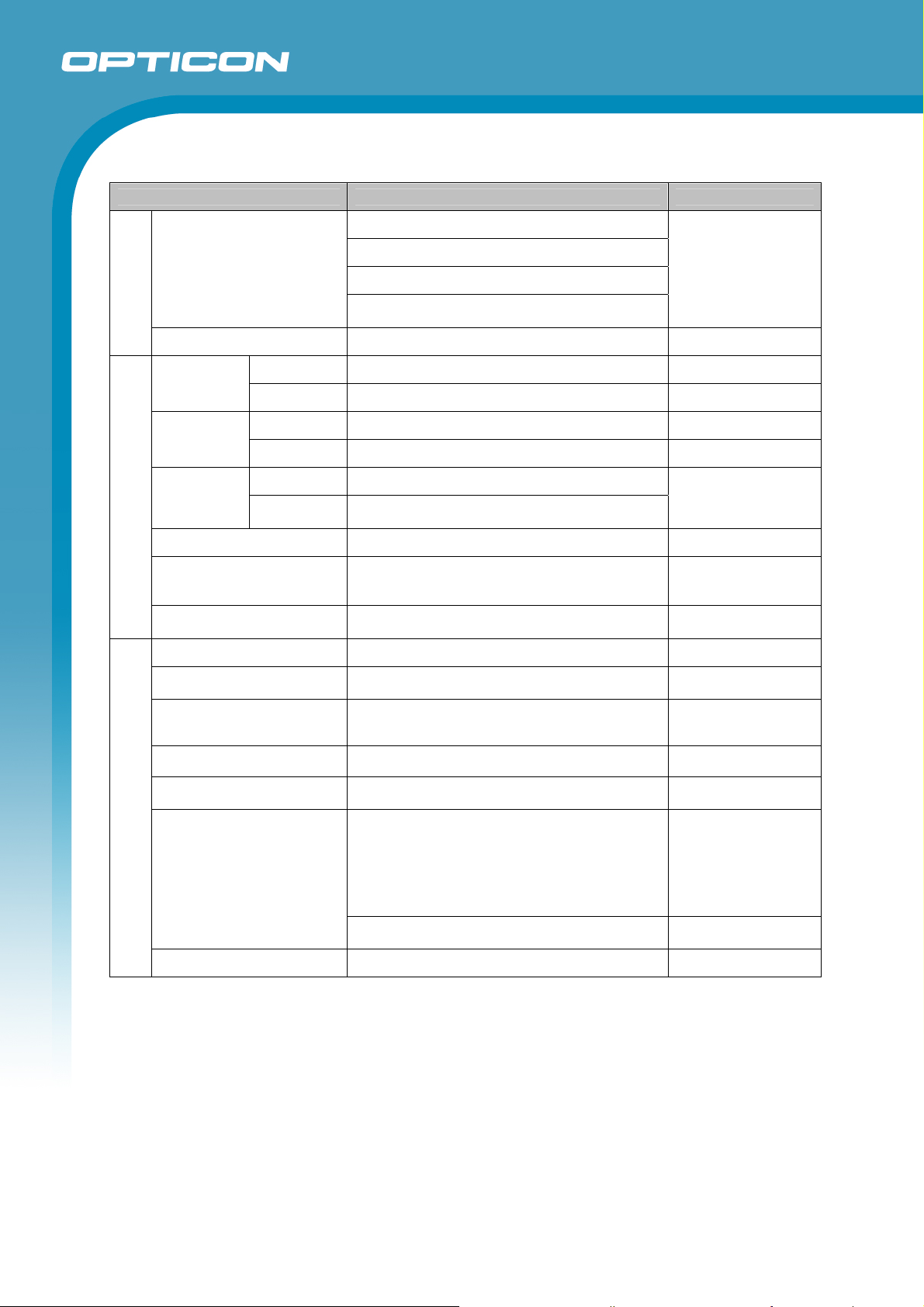
3. Basic Specifications
Item Specification Note
Section
ASIC OEY-0603
Control
SDRAM 128 Mbits (1 M × 4 Banks × 32 Bits)
OPI-3301
Specifications Manual
CPU: ARM-1026EJ-S
Core: 160 MHz
SDCLK: 80 MHz
Flash ROM 16 Mbits (1 M × 16 Bits) Flash Memory
Frequency 2402 MHz ~ 2480 MHz
Wireless Section
Specification Bluetooth V2.0 compliant
Transmission output Class 2 (up to 4 dBm)
Communication distance 10 meters
Profile SPP
Antenna 1/4λ surface-mount type
Optical Section
Scanning method CMOS area sensor
Scanning light source InGaAIP 1 red LED
Effective pixels (H: 900 x V: 512)
View angle
Horizontal: about 40°
Vertical: about 23°
UPC-A, UPC-A Add-on, UPC-E, UPC-E Add-on,
EAN-13, EAN-13 Add-on, EAN-8, EAN-8 Add-on,
Supported 1D Symbologies
Symbologies
JAN-8, JAN-13, Code 39, Tri-Optic, Codabar
(NW-7), Industrial 2 of 5, Interleaved 2 of 5, Code
93, Code 128, EAN-128, S-Code, MSI/Plessey,
UK/Plessey, TELEPEN, Matrix 2 of 5, Chinese
Post Matrix 2 of 5, IATA, Code 11, Korean Postal
Authority code, GS1 DataBar, Postal Code
Minimum resolution Code 39: 0.1 mm
Curvature
Radius ≧ 15 mm (8-digit JAN)
Radius ≧ 20 mm (13-digit JAN)
Resolution (0.127) 15 ~ 55
Depth of field
(mm)
Code 39
Resolution (0.254) 15 ~ 200
Resolution (1.0) 90 ~ 870
PDF417, MicroPDF417, QR Code , Micro QR
Symbologies
Supported 2D Symbologies
Code, DataMatrix (ECC 0 - 140 / ECC 200),
MaxiCode (Modes 2 to 5) , Aztec Code ,
EAN.UCC Composite bar code , Codablock F
Minimum resolution (mm) QR Code:0.127 mm DataMatrix: 0.169 mm
It may be shorter
depending on usage
environment
Frame rate: 80 fps
(fastest)
The GS1 DataBar is
formerly called “RSS”.
PCS 0.9
PCS 0.9
PCS 0.9
Disable Code 128
when Codablock F is
active.
PCS 0.9
Depth of field
(mm)
PDF417
Resolution (0.127) 15 ~ 70
Resolution (0.254) 20 ~ 210
QR Code Resolution (0.339) 15 ~ 170
PCS 0.9
Resolution (0.169) 15 ~ 40
DataMatrix
Resolution (0.339) 15 ~ 100
Micro QR Resolution (0.212) 15 ~ 65
7
Page 8
OPI-3301
Specifications Manual
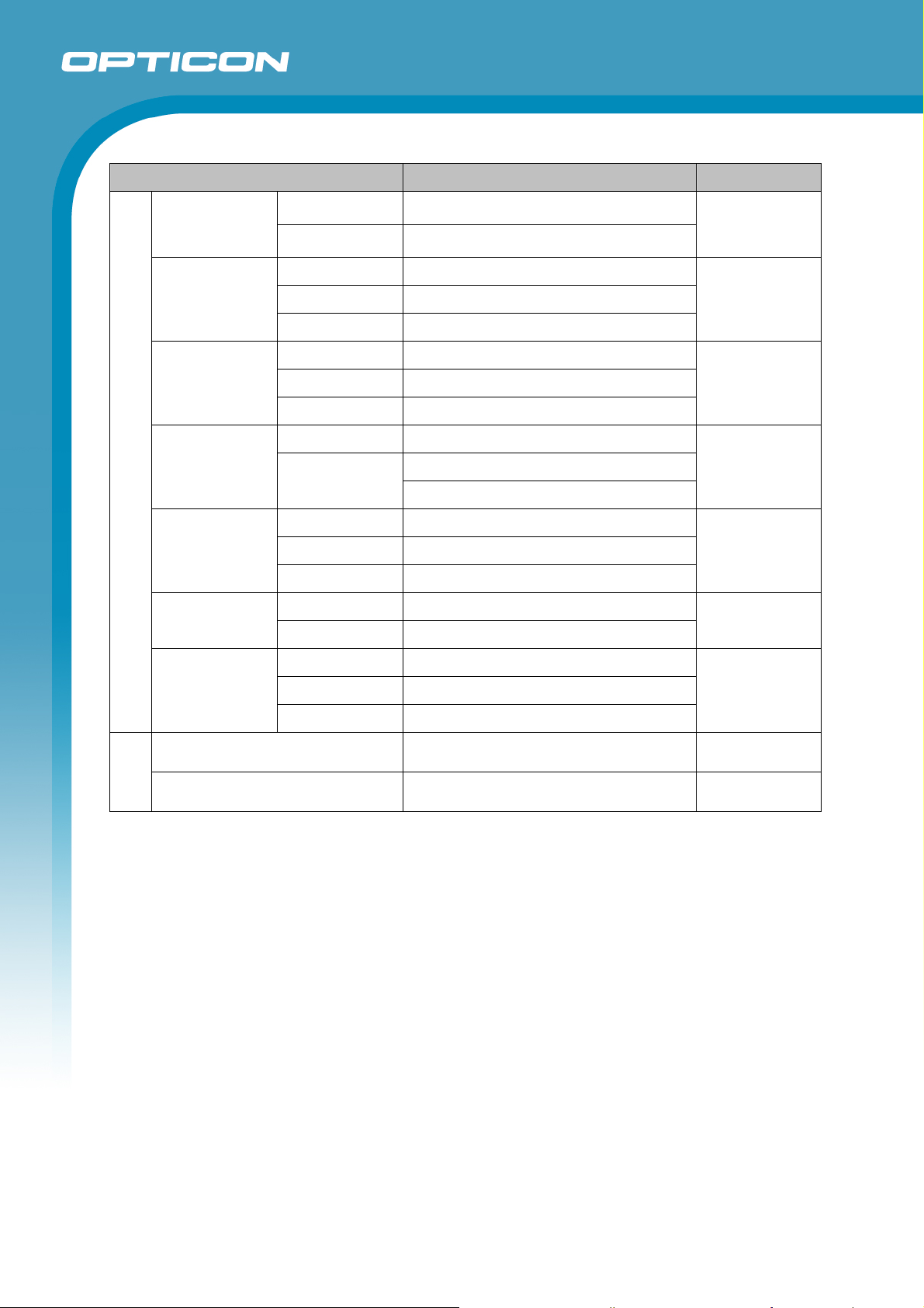
Item Specification Note
1/2 D Common
Pitch: ±50° (Skew β = +15°)
Skew: ±50°
Scan angle
Tilt: 360° (Skew β = +15°)
*There are some areas in which scanning fails
due to specular reflection.
Minimum PCS 0.45 or more
Operating -20 ~ 50°C
Temperature
Environmental Specifications
Storage -25 ~ 60°C
Operating 20 ~ 85% (no condensing, no frost)
Humidity
Storage 20 ~ 85% (no condensing, no frost)
Ambient light
immunity
Fluorescent 10,000lx or less
Sunlight 100,000lx or less
Dust and drip proof IP42
Increase the frequency of vibration from 10 Hz to
Vibration
100 Hz at an accelerated velocity of 19.6 m/s2
(2G) for 60 minutes each in X, Y and Z-direction.
Drop
Drop 3 times (18 times in total), at each 6 face,
from a height of 150 cm onto a concrete surface.
LED safety IEC 62471:2006 Exempt Risk Group
Laser safety
EMI
Regulatory (*)
Safety standards IEC/EN 60950-1
Immunity standards
IEC 60825-1:2007 Laser Class 1,
21 CFR 1040.10 & 1040.11 (CDRH) Class 1
VCCI Class-B / EN55022 Class-B /
FCC Part15,C
EN 610000-4-2, -4-3, -4-4,- 4-5, -4-6, -4-11
Class B
CE Marking
Product safety
Certification for Construction Design of Specified
Radio Equipment
Logo certification Bluetooth logo certification
Code: Code 39
Resolution: 0.254 mm
Distance: 100 mm from
the edge of the
scanner
*Curvature R = ∞
MRD: 32% or more
AC adapter: 0 ~ 40°C
QR Code
(Resolution: 0.25 mm)
Optical axis angle: 75°
DOF: 100 mm
Peak wavelength:
650 nm
Residential,
commercial and lightindustrial environments
Information technology
equipment
R&TTE directive
EN300 328
V1.6.1:2004
EN301 489-1
V1.5.1:2004
EN301 489-17
V1.2.1:2002
Radio Law 38-24-1
8
Page 9
ESD immunity
Radio-frequency
electromagnetic
field. Amplitude
modulation
OPI-3301
Specifications Manual
Item Specification Note
No destruction
No malfunction
Frequency 80 ~ 1000 MHz
Level 3 V/m
15 kV (apply static electricity 50 times to the
surface of the scanner)
Contact discharge (direct / indirect): ±6 kV
Air discharge (direct): ±8 kV
Condition:
IEC:61000-4-2
compliant
Condition:
IEC61000-4-3
compliant
AM 80% (AM)
Voltage Alternating-current input cable: ±1 kV
Fast transient
Immunity Test (*)
Pulse 5 / 50 ns (Tr / Tw)
Frequency 5 kHz
Pulse 1.2 / 50 μs (Tr / Th)
Surge
From L to P : ±2 kV (closed-loop voltage)
Voltage
From L to L : ±1 kV (closed-loop voltage)
Frequency 0.15 ~ 80 MHz
Radio-frequency
common mode
Level 3 V
AM 80% (AM)
Power frequency
magnetic field
Voltage dip,
momentary
voltage drop,
fluctuation
Features
Physical
Dimensions Approx. 56 × 113 × 137 (WDH mm)
Frequency 50, 60 Hz
Level 3 A/m
Dip 1 Drop 30%, 0.5 cycles
Dip 2 Drop 60%, 5 cycles
Momentary drop Drop > 95%, 250 cycles
Weight Approx. 110 g
Condition:
IEC61000-4-4
compliant
Condition:
IEC61000-4-5
compliant
Condition:
IEC61000-4-6
compliant
Condition:
IEC61000-4-8
compliant
Condition:
IEC61000-4-11
compliant
(*) : Items in combination with the communication cradle are included.
9
Page 10
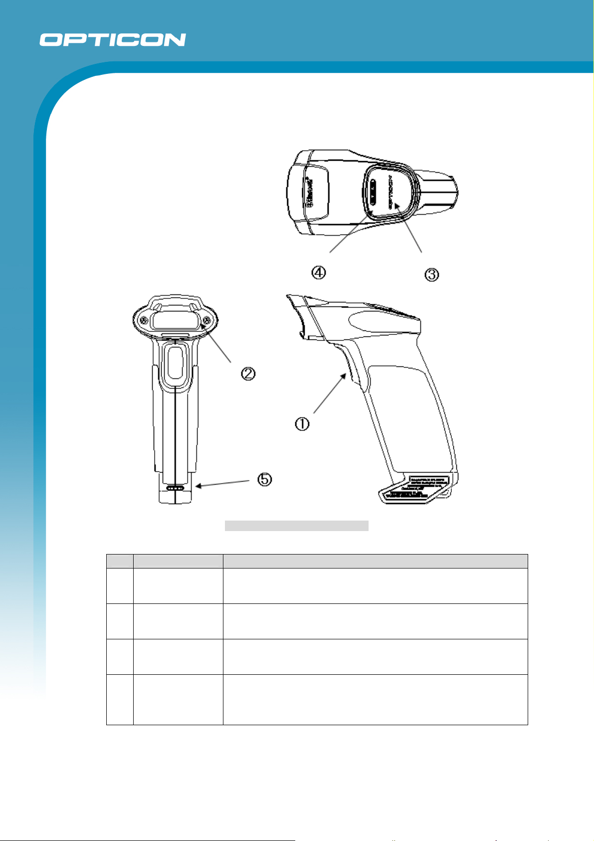
4. Detailed View
OPI-3301
Specifications Manual
Figure 1: Detailed View of OPI-3301
No. Name
Trigger Key
1
2 Scanning Window
3 Status LED
Laser aiming light is emitted by pressing this key to read 1D/2D
codes.
The laser light is emitted through this window. Ensure that the lens
is not exposed to dust and dirt before scanning.
The operating status is indicated by each LED color (see 4.1. for
details).
Description
A sound from a built-in buzzer comes out through these holes.
When they are covered, the buzzer sound may not be able to be
4 Buzzer Hole
heard. The sound varies depending on the status (see 4.1. for
details). Buzzer settings can be configured in various ways: enable
or disable buzzer as well as change the loudness and duration.
10
Page 11
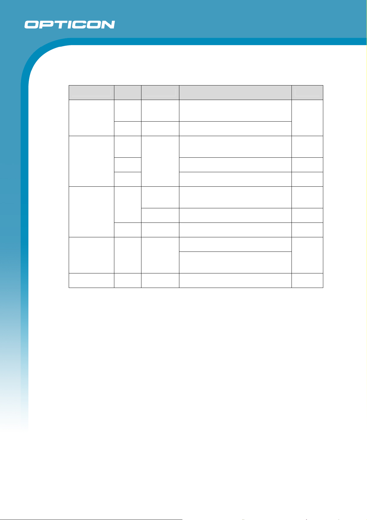
4.1. Status LED and Buzzer
The operating state is indicated by LED colors and buzzer sound.
State
Bar code
Read
Wireless
Connection
Wireless
Disconnection
Low Battery
Power
LED
Color
Indication
Red ON
Green ON
Blue
Red
Blinking
Green
Continuous
Blue
Blinking
ON
Red ON
Red ON
Orange ON
Charging: When the scanner is
placed on the cradle, the LED lights up
to indicate the scanner is charged. Charging
Fully charged: LED color changes
from Red to Green.
Successful: Bar code reading /
transmission has been done
successfully.
Failed: Bar code data was not able to
be transmitted.
Storing data: Bar code data is stored
in the memory in the scanner.
Connecting: The scanner is
attempting to establish a wireless
connection
Connected: The wireless connection
has been established.
Failed: The wireless connection was
unable to be established.
Disconnected: The wireless
connection is disconnected.
Lost: The wireless connection is lost
due to out of the range of
communication.
The remaining battery pack power
level is low. Recharge is required.
Description
OPI-3301
Specifications Manual
Buzzer
―
Pi
Pi-pi-pi
Pi
―
Piro-pi
Pi-pi-pi
Pi-ro
―
11
Page 12
5. Electrical Specifications
5.1. Configuration
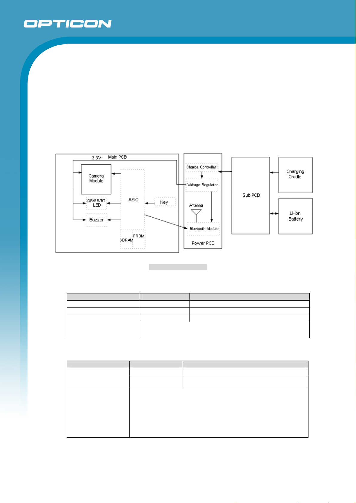
The OPI-3301 consists of
- Camera Module section, where images are captured and output as analog data.
- Decode and Wireless Communication Control section, where the signals from the camera
section are processed. This section also controls the whole system.
- Interface section that contains the user interface.
- Power supply section that contains the power supply and the battery charger.
The power is supplied from the battery pack or the CRD-3301.
OPI-3301
Specifications Manual
5.2. Current Consumption
Item Spec Remarks
Standby 150 mA or less With wireless connection
Sleep 1 mA or less
Operating Current 300 mA or less During reading, communication, LED ON
Measurement Condition
Others
5.3. Charging Current
Item Spec Remarks
Approx. 600 mA With RS-232C connection (AC adapter)
Charging CRD-3301
Measurement
Condition
Others
Approx. 300 mA
- Measured at 25°C
- Changing should be done at 0 ~ 40°C
- When the temperature is over 40°C, the protection function
Figure 2: Block Diagram
- Power supply voltage 3.7 V, 25 °C
- The operating current is measured in Test mode.
With USB connection
Bus-Power Class: Hi-POWER (500 mA)
start working and it may stop charging.
- To protect the scanner when the power supply is abnormal,
charging stops when the applied voltage to the charging
contacts is not within about 3 ~ 6 V.
12
Page 13
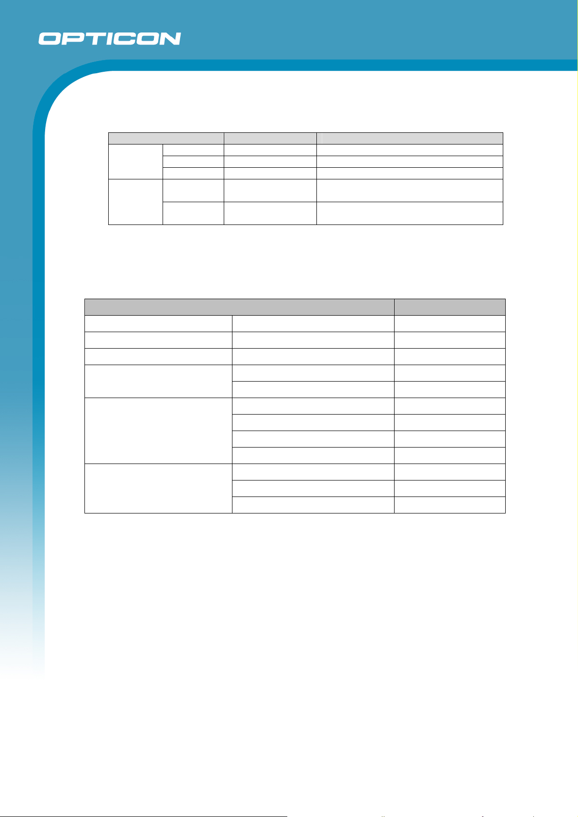
5.4. Operating and Charging Time
Item Spec Remarks
Battery
Life
Charging
Time
Sleep 200 hours or more
Standby Approx. 12 hours With wireless connection
Reading Approx. 10 hours 1 scan / 5 sec with wireless connection
Charging
time 1
Charging
time 2
Approx. 3 hours
Approx. 6 hours
The above specification may not be satisfied when the battery pack is degraded.
6. Optical Specifications
Item Characteristics
OPI-3301
Specifications Manual
When the cradle is connected with RS232C.
When the cradle is connected with USB
(Bus-Power supply)
Scan method CMOS area sensor (white / black) -
Number of effective pixel (*1) (Column) × (Row) 900 × 512 dots
Image capture speed Frame rate 80 fps
View angle
Auxiliary light source (LED)
Light source for aiming /
ranging (Laser diode)
Note:
*1: Readable pixel count: 1282 (column) × 1026 (row) dots.
*2: Reference value extracted from the datasheet.
*3: Reference value based on the datasheet (25°C, IF = 50 mA ).
Class 1M compliant output: Refer to the Chapter 14 for further information.
*4: Class 1 compliant output: Refer to the Chapter 14 for further information.
Horizontal Approx. 40°
Vertical Approx. 23°
InGaIP red LED -
Peak wave length 645 nm
Directivity angle: 2Φ 1/2 (*2) 60°
Maximum radiation output (*3) 5040 mcd
Red laser diode -
Peak wave length 650 nm
Maximum radiation output (*4) 390 μW
13
Page 14
OPI-3301
Specifications Manual
7. Technical Specifications
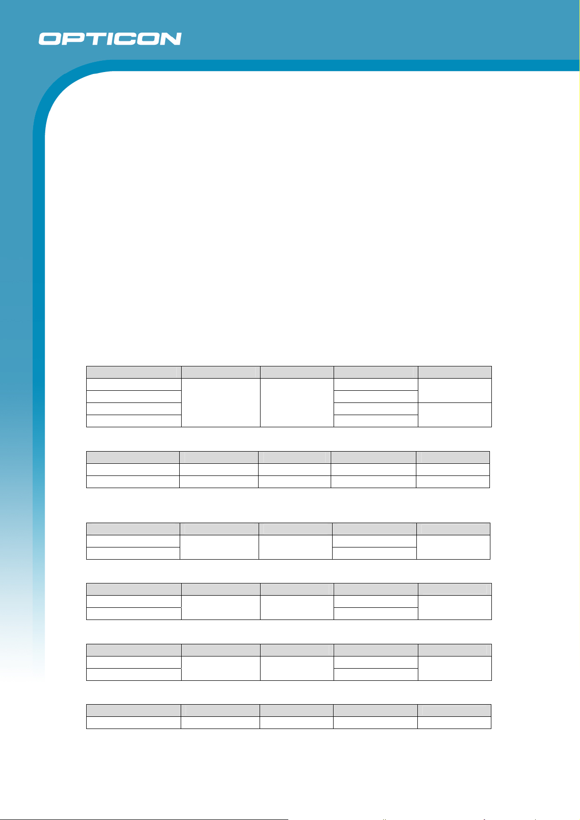
Aim the laser light at the center of a code to scan it. For long distance scanning, ambient light
entering the angle of view may affect the scanning performance. The conditions for technical
specifications are as follows, unless otherwise specified in each section.
<Conditions>
Ambient Temperature and Humidity Room temperature, room humidity
Ambient Light 1000 ~ 1500 lx (on code surface)
Angles Pitch: α = 0°, Skew: β = 15°, Tilt: γ = 0°
Curvature R = ∞
Power Supply Voltage 3.7 V
PCS (1D and 2D) 0.9 or higher
Reading Test Judge within 2 seconds for every 2 scanning. Accept the
performance with 70% or more success rate for 10 tries.
Barcode Test Sample (1D and 2D) Specified below. Code 39 (resolution 0.1 and 0.127 mm) and
JAN codes are OPTOELECTRONICS test samples. Others
are printed by a normal printer. (NW ratio = 1 : 1.25)
Supported 1D symbology
<Code 39>
Resolution Symbology PCS Size (mm) No. of digits
0.1 mm 10 × 9
0.127 mm 11 × 10
0.254 mm 14 × 10
1.0 mm
<JAN>
Resolution Symbology PCS Size (mm) No. of digits
0.260 mm 13-digit JAN 0.9/0.45 25 × 19 13
0.260 mm 8-digit JAN 0.9 17.5 × 15.5 8
Supported 2D symbology
<PDF417>
Resolution Error correction PCS Size (mm)
0.254 mm 26 × 16.5
0.127 mm
<QR Code: Model-2>
Resolution Error correction PCS Size (mm)
0.339 mm 10 × 10
0.127 mm
<Data Matrix>
Resolution Model PCS Size (mm)
0.339 mm 8 × 8
0.169 mm
<MicroQR>
Resolution Error correction PCS Size (mm)
0.212 mm L 0.9 5 × 5 11
Code 39 0.9
Level-4 0.9
M 0.9
ECC200 0.9
56 × 30
13 × 8
4 × 4
4 × 4
4
2
No. of characters
17
No. of characters
44
No. of characters
40
No. of characters
14
Page 15
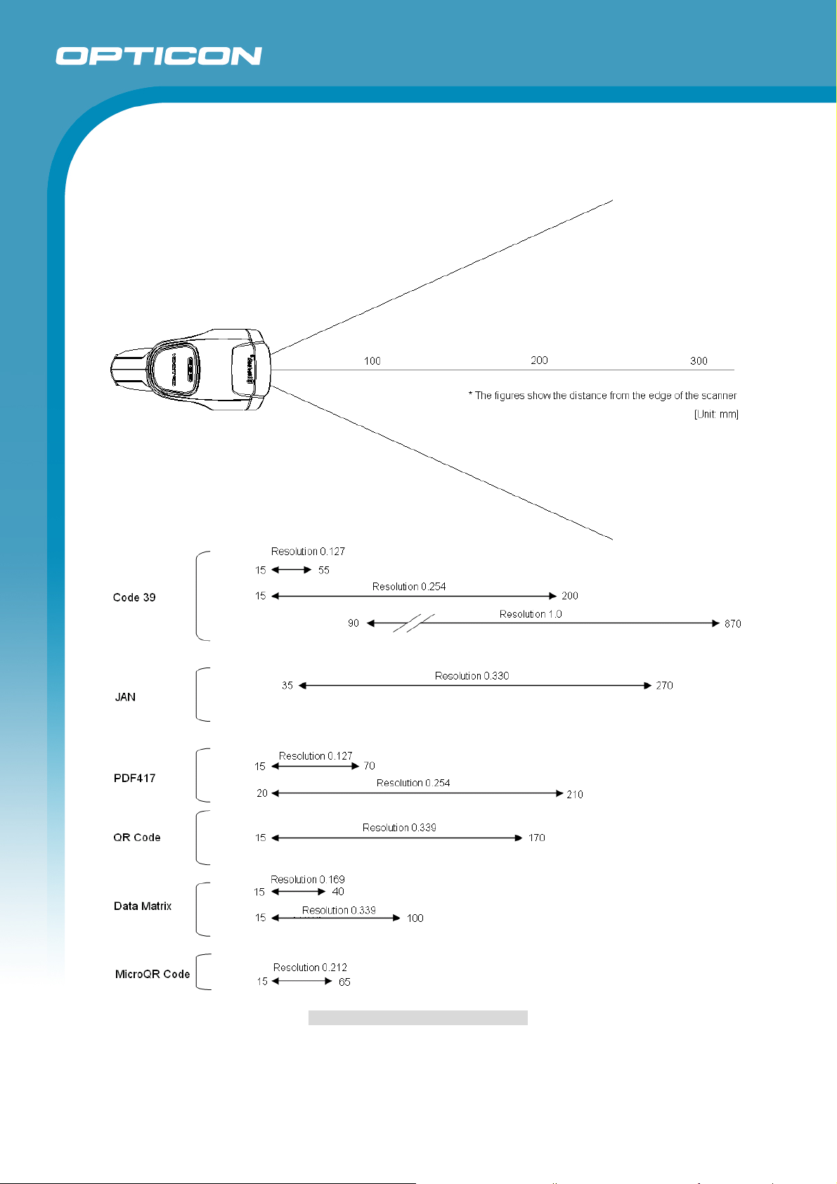
7.1. Scan Area and Depth of Field
OPI-3301
Specifications Manual
Figure 3: Scan Area and Depth of Field
15
Page 16
7.2. Printed Contrast Signal (PCS)
0.45 or higher (70% or more reflectivity of space and quiet zone)
PCS =
* Be sure to keep the optical window clean without dirt or scratches, or it may have a bad
effect on the reading characteristics..
Reflectance of white bar-Reflectance of black bar
Reflectance of white bar
7.3. Minimum Resolution
0.1mm : Code 39 (specified in Chapter 7)
0.127mm : PDF417, QR code (specified in Chapter 7)
0.169mm : Data Matrix (specified in Chapter 7)
0.212mm : Micro QR (specified in Chapter 7)
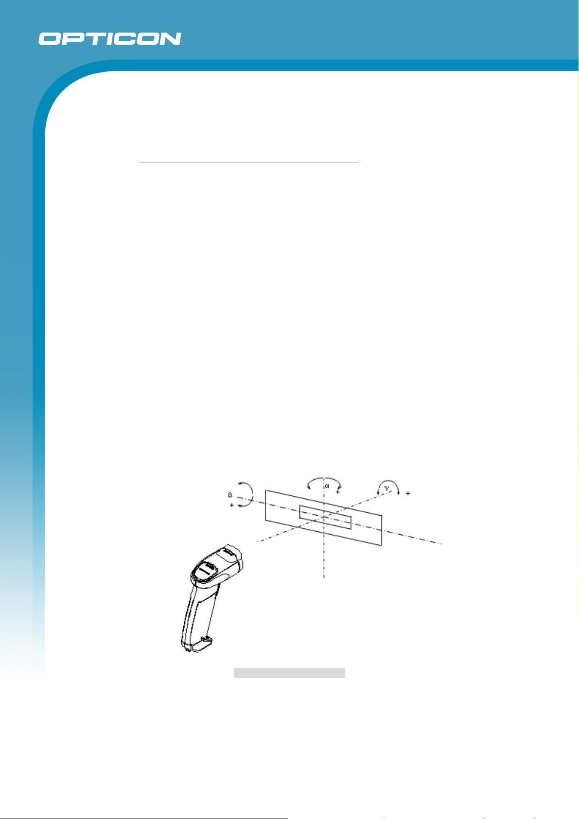
7.4. Pitch, Skew and Tilt
Pitch angle α = ±50°
Skew angle β = ±50°
Tilt angle γ = 360°
<Conditions>
Barcode Sample
(1D and 2D)
Distance : 80 mm from the front edge of the scanner.
Angle : Pitch angle measurement - set the skew angle β = 15° fixed.
Curvature : R = ∞
: Code 39 specified in Chapter 7
OPI-3301
Specifications Manual
(Resolution 0.254 mm, PCS 0.9)
Tilt angle measurement - set the skew angle β = 15° when pitch angle
is 0° and rotate 1D/2D codes.
Figure4: Pitch, Skew and Tilt
16
Page 17
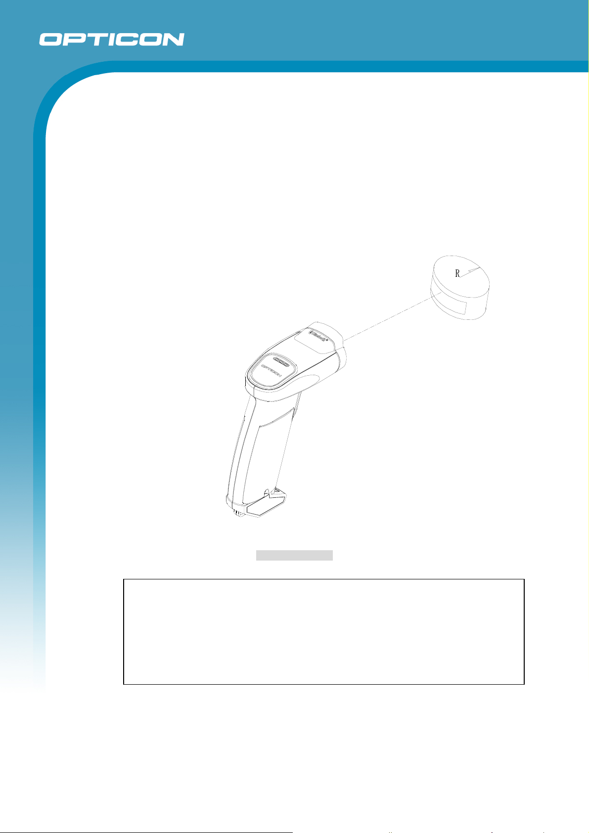
7.5. Curvature
8-digit JAN : R ≥ 15 mm
13-digit JAN : R ≥ 20 mm
<Conditions>
Barcode Test Sample
(1D and 2D)
Distance : 80 mm from the front edge of the scanner.
Angles : Skew: β = 15°
OPI-3301
Specifications Manual
: PCS 0.9, Resolution 0.26 mm, Quiet Zone 10 mm
as specified in Chapter 7
Figure 5: Curvature
Note: Scanning may fail due to the specular reflection of illumination LEDs
when the reflectivity is high. In that case, scan the code tilting the scanner in
the skew direction or set the illumination LED off so that the performance
can improve. Make sure of the sufficient environmental illuminance (500 lx
or more) when the illumination LED is off to keep the scanning
performance. The ambient lights also may cause the reflection and the
degraded scanning performance.
17
Page 18

Specifications Manual
8. Bluetooth
OPI-3301 uses Bluetooth as a wireless interface: Compliant with Bluetooth specification version
1.2, supporting Serial Port Profile (SPP).
• Implemented Profile
SPP (Serial Port Profile)
• Communication Configuration
1 to 1
* 1 to N (Multiple-channel) is not supported.
• Operating Mode in Communication
Master : OPI-3301
Slave : CRD-3301 and other Bluetooth devices
• Power saving
Low-power sniff mode is not supported
OPI-3301
• Security and Encryption
Authentication and Encryption are supported
• Communication Distance
Approx 10m
18
Page 19
OPI-3301
Specifications Manual
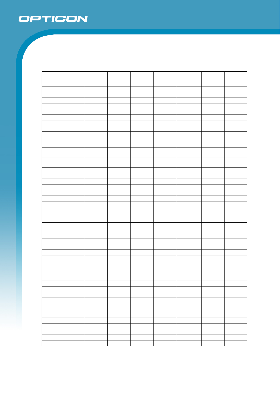
9. Default Settings
The OPI-3301 is set to the following factory default settings by reading menu code “SO”.
Default Settings 1: Readable Codes
Transmit
Code type Read
UPC-A ○ × ○ ○ - CR
UPC-A Add-on × × ○ ○ - CR
UPC-E ○ × ○ ○ - CR
UPC-E1 × × ○ ○ - CR
UPC-E Add-on × × ○ ○ - CR
EAN-13 ○ × ○ ○ - CR
EAN-13 Add-on × × ○ ○ - CR
EAN-8 ○ × ○ ○ - CR
EAN-8 Add-on × × ○ ○ - CR
Code 39 ○ × ○ ×
Tri-Optic ○ × - -
Codabar (NW-7) ○ × ○ ×
Industrial 2 of 5 ○ × ○ × - CR
Interleaved 2 of 5 ○ × ○ × - CR
Code 93 ○ × - ○ - CR
Code 128 ○ × - ○ - CR
EAN-128 × × - ○ - CR
S-Code ○ × ○ × - CR
MSI/Plessey ○ × ○ ○
UK/Plessey ○ × ○ ○ - CR
TELEPEN ○ × × ○ - CR
Matrix 2 of 5 × × ○ × - CR
Chinese
Post Matrix 2 of 5
IATA ○ × ○ × - CR
Code 11 × × × ○ - CR
Postal Code (JPN) × × - ○ - CR
Postal Code (USPS) × × - ○ - CR
Postal Code
(POSTNET)
Korean Postal
Authority code
PDF417 ○ × - ○ - CR
QR Code ○ × - ○ - CR
Micro QR Code ○ × - ○ - CR
DataMatrix
(ECC200)
DataMatrix
(ECC0-140)
MaxiCode ○ × - ○ - CR
MicroPDF417 ○ × - ○ - CR
Aztec Code ○ × - ○ - CR
Aztec Runes × × - ○ - CR
Codablock F × × - ○ - CR
Note: Disable Code 128 when enabling Codablock F. The scanner may incorrectly recognize a broken
Codablock F as Code 128.
× × ○ × - CR
× × - ○ - CR
× × × ○ - CR
○ × - ○ - CR
× × - ○ - CR
Code
Length
Transmit
CD
Calculate
CD
Transmit
Other
Not transmit
ST/SP
Not transmit
ST/SP
Not transmit
ST/SP
Not transmit
CD2
Set Prefix Set Suffix
- CR
- CR
- CR
- CR
19
Page 20
Specifications Manual
Transmit
Code type Read
GS1 DataBar Omnidirectional
GS1 DataBar Truncated
GS1 DataBar Stacked
GS1 DataBar
Stacked Omnidirectional
GS1 DataBar Limited
GS1 DataBar Expanded
GS1 DataBar Expanded Stacked
Composite EAN
EAN-13 CCA
EAN-13 CCB
EAN-8 CCA
EAN-8 CCB
Composite UPC
UPC-A CCA
UPC-A CCB
UPC-E CCA
UPC-E CCB
Composite GS1 DataBar
CCA
CCB
Limited CCA
Limited CCB
Expanded CCA
Expanded CCB
Composite GS1-128
CCA
CCB
CCC
GS1 DataBar and GS1-128 are formerly called RSS and UCC/EAN-128 respectively.
Code
Length
○ × ○ ○ - CR
○ × ○ ○ - CR
○ × - ○ - CR
× ×
× ×
× ×
× × - ○ - CR
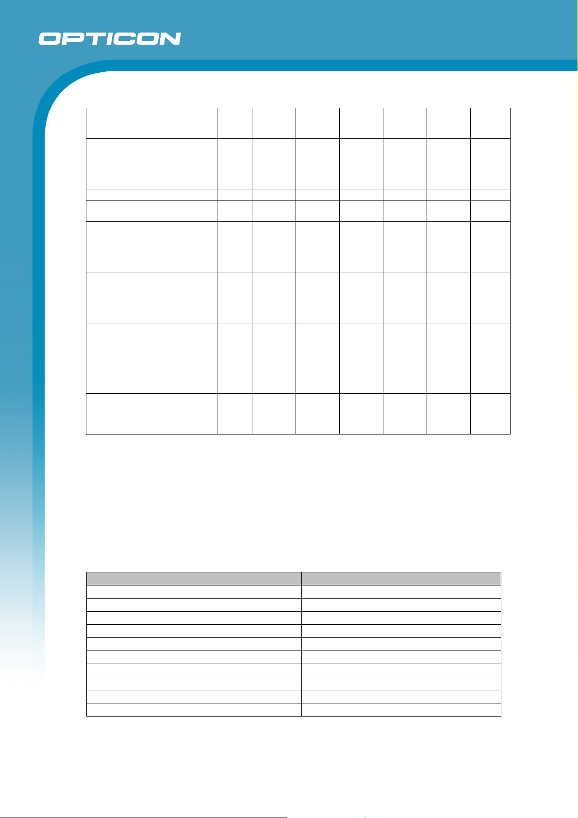
Notes:
(1) “Reading” column ○ : Enable reading, × : Disable reading.
(2) “Transmit code length” column ○ : Transmit code length” , × : Do not transmit code length ,
- : Not supported.
(3) “Transmit CD” column ○ : Transmit check digit , × : Do not send check digit.
(4) “Calculate CD” column ○ : Calculate check digit, × : Do not calculate check digit.
(5) “Prefix” column - : No prefix setting
(6) For USB setting, the suffix setting is “Enter [0x84]” (Direct input keyboard keys menu “7I”.)
Default Settings 2: Wireless Communication Settings
Item Default setting
Setting the number of characters
Read mode
Multiple read (code only)
Multiple row read
Trigger switch
Read time
Buzzer duration
Buzzer tone
Buzzer loudness
Indicator LED duration
Transmit
CD
(1D code)
(1D code)
(1D code)
○
○
○
Calculate
CD
Transmit
Other
○ - CR
○ - CR
○ - CR
Fixed length OFF all codes
Single read
Disable
Disable
Enable
2 seconds
50 ms
3 kHz
Volume 1 (max)
200 ms
Set Prefix
OPI-3301
Set
Suffix
20
Page 21
Specifications Manual
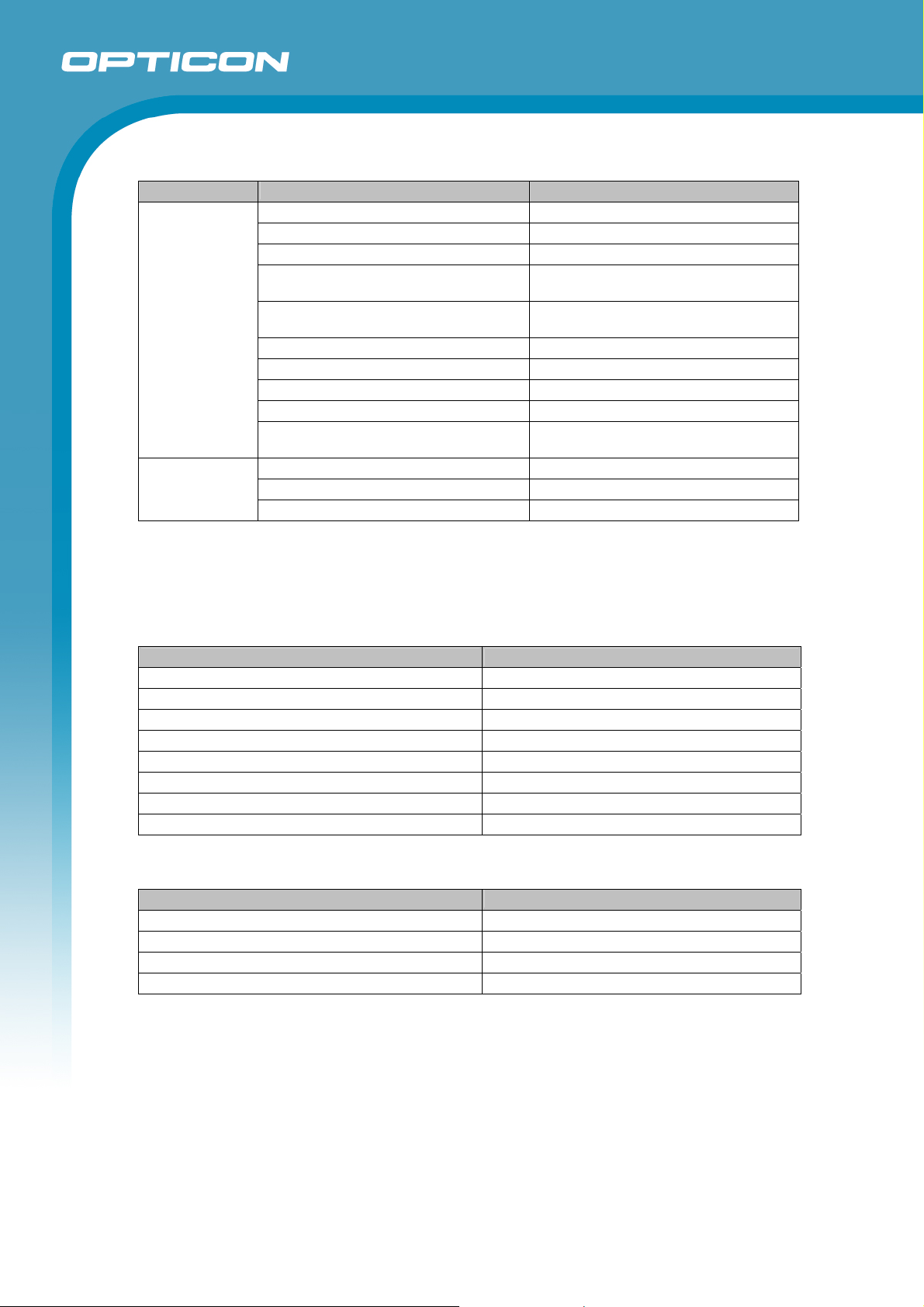
Default Settings 3: Wireless Communication Settings
Item “UB” Default Setting
Set connection Connect to RS-232C cradle
Data memorizing Disable
Trigger connect / disconnect Disable
Wireless
communication
settings
Trigger connect
(time to press switch)
Trigger disconnect
(time to press switch)
Auto disconnect Disable
Disable
Disable
Auto reconnect 5 minutes
ACK/NAK No control
ACK/NAK time out 1 second
Set (connect to the last 4 digits of BD
address)
Bluetooth
settings
Pin code
BT address auto connect Enable
Authentication Enable (auto pairing)
Encryption Disable
* The interface to connect the CRD-3301 and the host is RS-232C by factory default.
* When USB is used to connect the CRD-3301 and the host, set to “Connect to USB-HID cradle”.
* Do not select “Connect to PC” in a combination of the OPI-3301 and the CRD-3301
Default Settings 4: Communication Settings between CRD-3301 and Host (RS-232C)
Item “U2” Default Setting
Baud rate 9600 bps
Parity bits No parity
Data length 8 bits
Stop bits 1 bit
Handshaking No handshake
ACK/NAK No control
CS time out Indefinitely
Intercharacter delay No delay
Default Settings 5: Communication Settings between CRD-3301 and Host (USB-HID)
Item “SU”/” C01” Default Setting
Keyboard language US
Numpad Do not use numpad (Full Key Code)
CAPSLOCK No CAPSLOCK mode
Intercharacter delay No delay
OPI-3301
21
Page 22
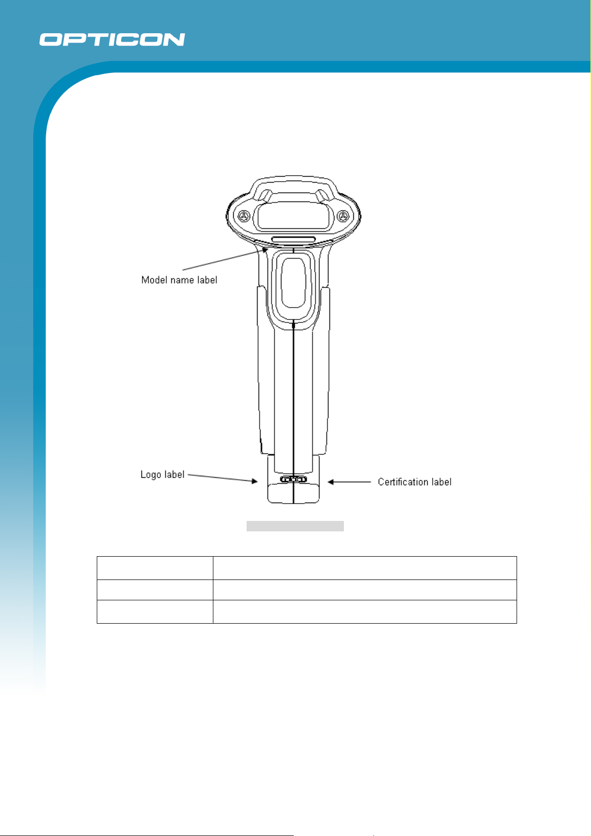
10. Product Labels
The labels shown below are attached to the scanner.
OPI-3301
Specifications Manual
Figure 6: Product Labels
Model name label
Logo label Shows certified standard logos.
Certification label
Shows the product name, serial number, month and year of
manufacture, laser caution and laser Class 2
Shows the standards-compliant languages and certificate
numbers.
22
Page 23
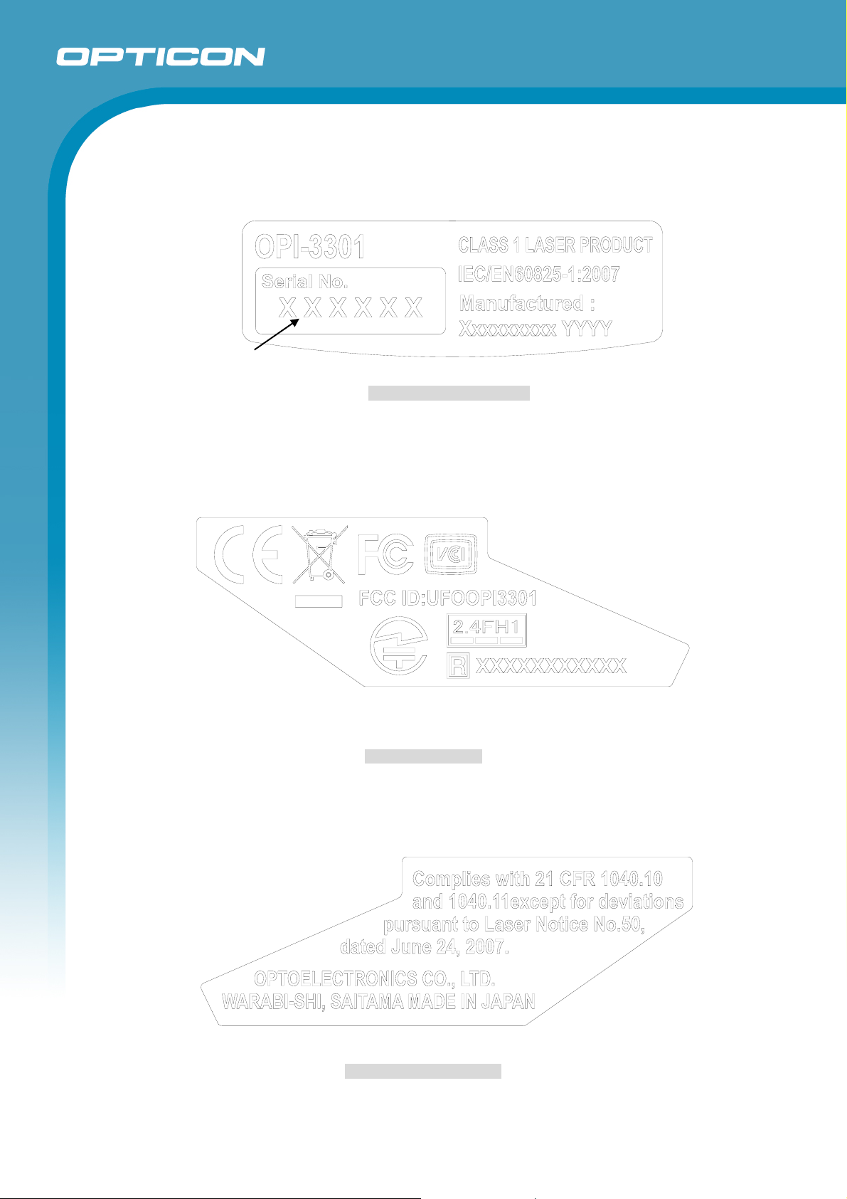
<Product Label 1>
Serial Number
OPI-3301
Specifications Manual
<Product Label 2>
<Product Label 3>
Figure 7: Model Name Label
Figure 8: Logo Label
Figure 9: Certification Label
23
Page 24
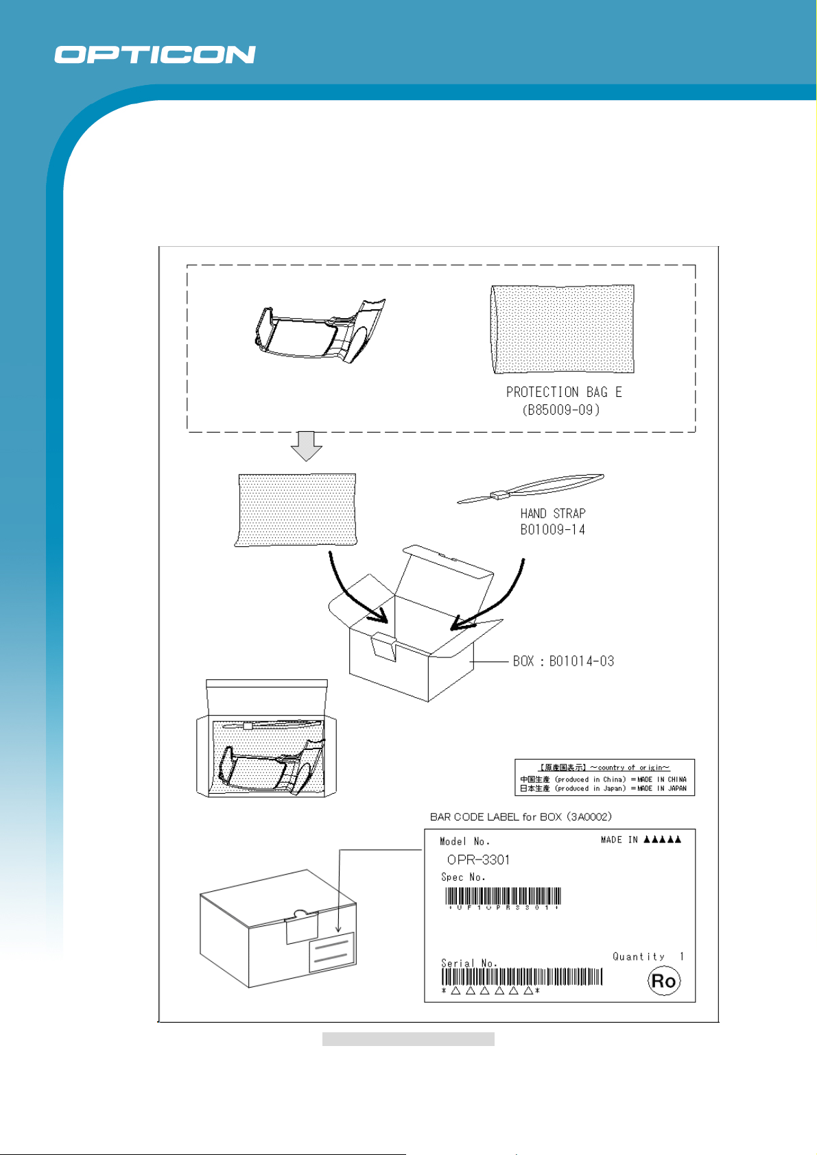
11. Packaging Specifications
11.1. Individual Packaging Specification
Assembled package size: 165 x 110 x 82 (WDH mm)
OPI-3301
Specifications Manual
Figure 10: Individual Packaging
24
Page 25
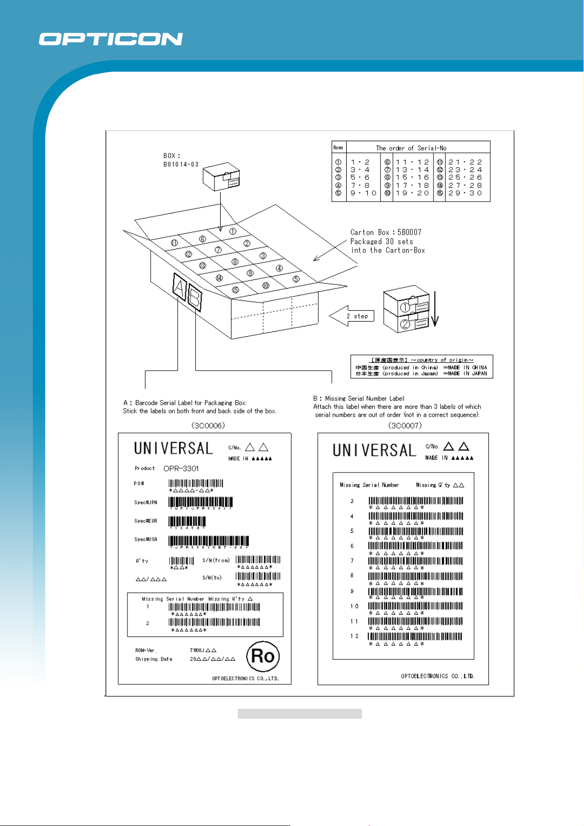
11.2. Collective Packaging Specification
Assembled package size: 585 x 520 x 200 (WDH mm)
OPI-3301
Specifications Manual
Figure 11: Collective Packaging
Note: ‘Ro mark’ on the trays and the boxes for the product indicates that the product is
RoHS compliant, which is declared by Optoelectronics Co., Ltd.
25
Page 26
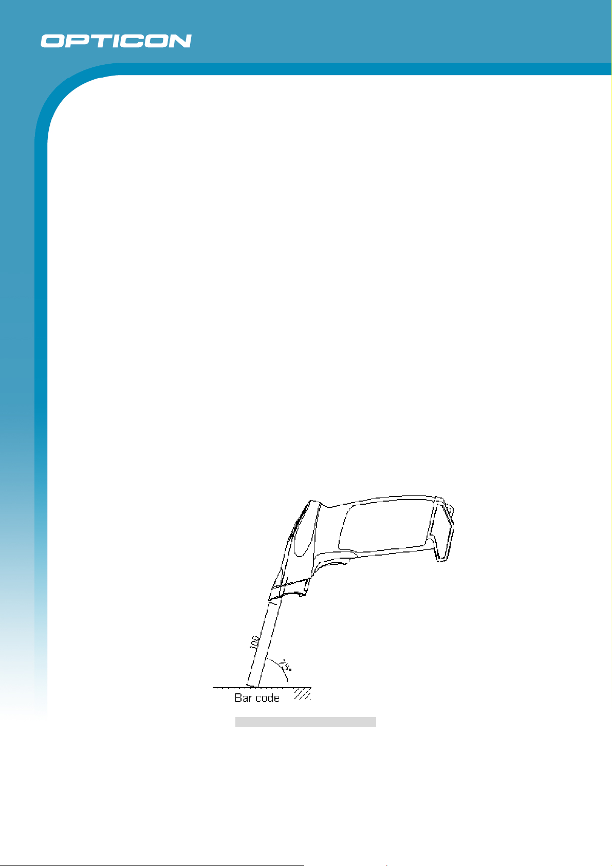
12. Environmental Specifications
12.1. Operating Temperature and Humidity
Temperature : -20 ~ 50°C (-0 ~ 40°C when charging)
Humidity : 5 ~ 85%RH (no condensation, no frost)
12.2. Storage Temperature and Humidity
Temperature : -25 ~ 60°C
Humidity : 5 ~ 85RH% (no condensation, no frost)
12.3. Ambient Light Immunity
Scanning performance is guaranteed when the range of illumination on a barcode surface
is the following values.
Incandescent light : 0 ~ 10,000 lx
Fluorescent light : 0 ~ 10,000 lx
Sunlight : 0 ~ 100,000 lx
<Conditions>
Barcode Test Sample OPTOELECTRONICS test chart
Resolution 0.254 mm PDF417 specified in Chapter 7
Distance 100 mm from the front edge of the scanner.
Angles Pitch: α = 0°, Skew: β = 15°, Tilt: γ = 0°
Curvature R = ∞
Power Voltage 3.7 V
* Be sure that the direct light or specular reflection from the light source does not enter
the light receiving section of the OPI-3301.
OPI-3301
Specifications Manual
Figure 12: Ambient Light Immunity
26
Page 27
12.4. Dust and Drip Proof
IEC IP42 equivalent
Protection against solid objects: Level 4
Protected against solid objects greater than 1.0 mm
Protection against liquids: Level 2 (JIS IPX2)
Protected against dripping water from the vertical when tilted up to 15°
12.5. Electrical Characteristics
The characteristics in combination with the communication cradle CRD-3301 is included.
Power Line Noise Immunity : ±1 kV
Power Line Noise Immunity : ±1 kV
Electrostatic Discharge Immunity : No destruction
*Note: Testing method is compliant with IEC-61000-4-2. (150 pf, 330 ohm)
Specifications Manual
±15 kV (air or direct discharge)
No malfunction
±10 kV (air or direct discharge),
± 6 kV (contact, direct or indirect discharge)
OPI-3301
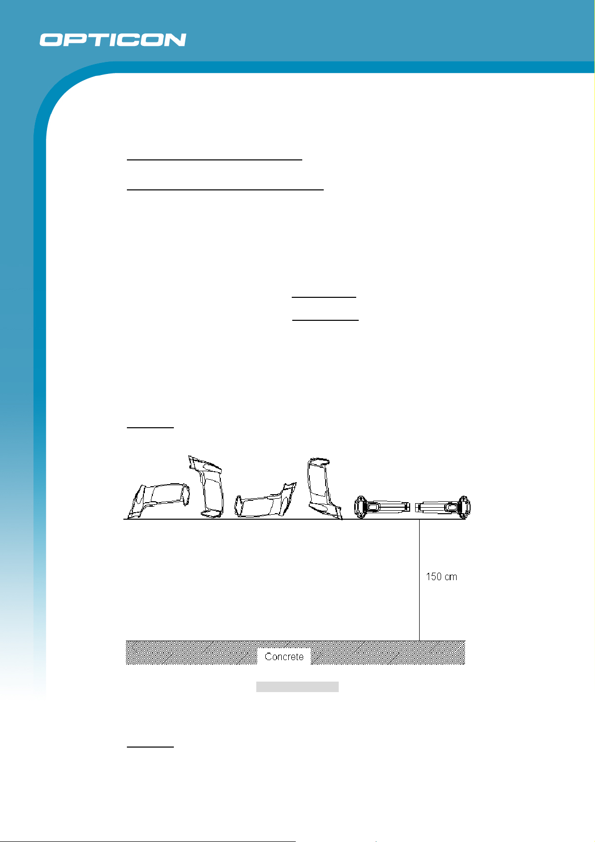
12.6. Drop Impact Strength (without packaging)
There shall be no sign of malfunction after the following drop test.
Drop test: Drop the scanner 8 times (48 times in total), at each 5 face, from a height of
150 cm onto a concrete floor as shown below.
Figure 13: Drop Test
12.7. Drop Impact Strength (in individual packaging)
There shall be no sign of malfunction after the following drop test.
Drop test:
edges, and 6 faces, from a height of 150 cm onto a concrete floor.
Drop an individually packaged scanner 10 times in total, at any of 1 corner, 3
27
Page 28
Specifications Manual
12.8. Vibration Strength
There shall be no sign of malfunction after the following vibration test.
Vibration test: Increase the frequency of the vibration from 10 Hz to 100 Hz at an
accelerated velocity of 19.6 m/s2 (2.0 G) for 60 minutes in the non-operating state.
Repeat this in each X, Y and Z direction.
13. Reliability
MTBF (Mean Time Between Failures) 40,000 hours (excluding the following parts)
Laser diode 10,000 hours
CMOS sensor 10,000 hours
Liquid lens 10,000 hours
* The value is based on the assumption of normal operation in the operating temperature range
without excessive electrical / mechanical shock or impact.
14. Regulatory Compliance
OPI-3301
14.1. LED Safety
IEC 62471:2006 Exempt Risk Group
14.2. Laser Safety
JIS C 6802:2005 Class 2
IEC 60825-1+A:2001 Class 2
CDRH ClassⅡ
14.3. Product Safety
IEC 60950-1:2005
EN 60950-1:2006/A11:2009
14.4. EMC
FCC Part 15 Subpart B Class B
This device complies with part 15 of the FCC Rules. Operation is subject To the following two
conditions: ( 1 ) this device may not cause harmful Interference, and ( 2 ) this device must accept
any interference received, including interference that may cause undesired operation.
VCCI Class B
This is a Class B product, to be used in a domestic environment, based on the Technical
Requirement of the Voluntary Control Council for Interference from Information Technology
Equipment (VCCI). If this is used near a radio or television receiver in a domestic environment, it
may cause radio interference.
14.5. Others
Certification for Construction Design of Specified Radio Equipment (Radio Law 38-24-1)
Bluetooth logo certification
R&TTE Directive EN 300 328
15. RoHS
The OPI-3301 is compliant with RoHS.
RoHS: The restriction of the use of certain hazardous substances in electrical and electronic
equipment, 2002/95/EC
EN 301 489-1
EN 301 489-17
EN 55022:2006
28
Page 29

16. Precautions
16.1. Precaution against Laser Light
*Use of controls or adjustments or performance of procedures other than those specified
herein may result in hazardous radiation exposure.
Caution - Do not stare into the laser light from a scanning window. It may harm your eyes.
Do not point the laser directly at others’ eyes. It may harm your eyes.
Do not stare into the beam with optical instruments. It may harm your eyes.
16.2. Precaution against LED Light
Do not stare into the LED light from a scanning window. It may harm your eyes.
16.3. Handling
Handle this product carefully. Do not deliberately subject it to any of the following:
(1) Shock:
・ Do not drop this product from a height greater than specified in this manual.
・ Do not swing the cable around.
OPI-3301
Specifications Manual
(2) Temperature Conditions:
(3) Foreign Materials:
(4) Others
16.4. Radio Low
This scanner qualifies as radio equipment for low-power radio stations (2.4 GHz band
advanced data communication systems) as specified in the Radio Law 38-24-1.The
scanner has obtained the Certification for Construction Design of Specified Radio
Equipment. Therefore it does not need to have a radio station license in Japan.
The following activities are prohibited under the Radio Law:
・ Remodeling and disassembly
・ Peeling off the certificate label
Do NOT use
affect other device and end up with causing physical or material damage.
・ Safety apparatus and medical device for human body protection
・ Environment where is concerned to cause serious damage
・ Do not use this product at temperatures outside the specified range.
・ Do not pour boiling water on this product.
・ Do not throw this product into a fire.
・ Do not immerse this product in water or other liquid.
・ Do not expose this product to chemicals.
・ Do not disassemble this product.
・ Do not use this product near a radio or a TV. It may cause reception problems.
・ Excessive static electricity may cause this product to malfunction.
・ This product may be affected by a momentary voltage drop caused by lightning.
・ This product may not perform properly in environments when placed near a flickering
light, such as a CRT (computer monitor, television, etc.).
・ Do not use excessive force to turn the screw for the battery cover. Adjust it within
indicated range.
the scanner under the following environment, as radio interference may
29
Page 30

16.5. Export Administration Regulations
This product is subject to the strategically controlled exports regulated under “Foreign
Exchange and Foreign Trade Laws”. Therefore, export of this product may require an
export permission of Japanese government.
16.6. Bluetooth
・ Bluetooth® is a registered trademark owned by its proprietor and used by
OPTOELECTRONICS Co., Ltd. under license.
・ To communicate via Bluetooth, the device that communicates with this scanner must
support the same Bluetooth version and profile as this scanner’s.
・ This scanner is compliant with Bluetooth standards. We cannot guarantee the
connection between this scanner and other Bluetooth devices which have not been
tested.
・ Bluetooth devices use 2.4 GHz frequency band, and many other sorts of devices also
utilize this frequency band. It may have affect the communication speed or
communication range of the scanner.
・ The communication speed and range may differ due to the obstacles and radio wave
conditions between this scanner and the device to which this scanner is connected.
・ Conditions of the device, to which this scanner is connected, may also affect the
communication speed and communication range of this scanner.
・ When any metallic object is present close to the upper posterior part of the scanner
where an antenna is installed, the communication may be affected.
・ An anticipated interference distance is 20 meters or less.
OPI-3301
Specifications Manual
16.7. Frequency Baud
The frequency band 2.4 GHz is utilized by this product. Read carefully the followings
before using this product.
In the frequency band of this product, scientific, medical and industrial devices including
microwaves are used. Also other radio stations including local private radio station for
mobile object identification requiring license for such as manufacturing lines at factories,
specific power-saving radio station requiring no license and amateur radio station are
managed.
1. Please make sure that “other radio stations” are not managed in the frequency band
2.4 GHz before using this product.
2. In case that radio interference occurs between this product and “other radio stations,”
change the service space immediately, or stop transmitting radio wave to avoid the
interference.
3. If you have any questions or troubles, please contact our sales office.
30
Page 31
Specifications Manual
17. Auto Trigger
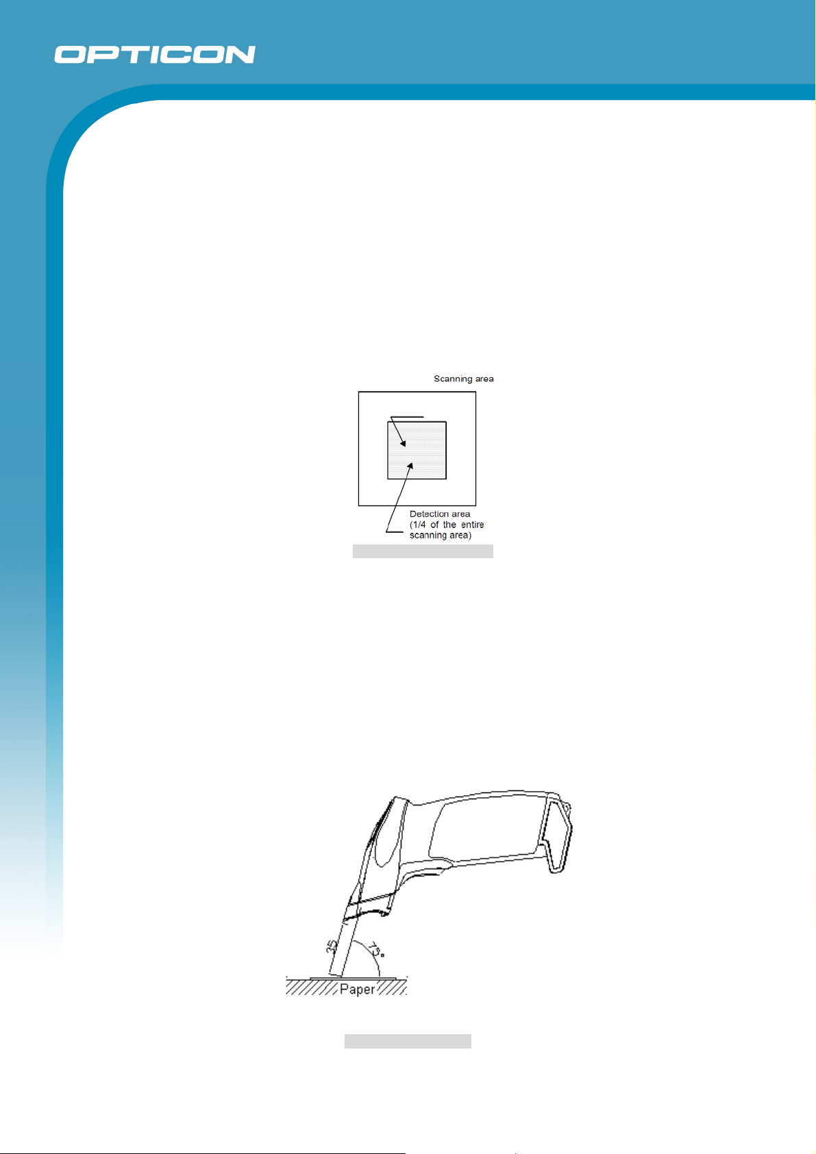
The OPI-3301 can be set to auto trigger mode. This means that the scanner starts scanning
automatically when it detects a change in brightness that occurs when a bar code label is
presented in front of it.
17.1. Outline of Operation
In auto trigger mode, the scanner captures a barcode image using the ambient light
and detects the brightness of multiple bright / dark parts in the detection area of the
image (a shaded area in the figure below). The scanner constantly monitors the
areas to see if the brightness is changed. When the brightness variations at regular
time intervals in either area is larger than the threshold value, the scanning operation
(multiple read) starts. After the elapse of the specified read time, the scanning stops.
OPI-3301
17.2. Specifications
Trigger is enabled when inserting a gray-colored paper on a black backing paper.
Trigger is also enabled when inserting a black-colored paper on a gray backing
paper.
<Conditions>
Paper used : Black paper from Glory called as Black 010010016
Gray paper from Glory called as Silver-gray 010010016
Ambient Light : 300 lx or more
Background Size : Larger than the scanning area
Detected Paper Size : Larger than the detecting area
Moving Speed of Detected Paper : 105 mm/second or slower
Ambient Temperature and Humidity : Room temperature and room humidity
Figure 14: Detection Area
Figure 15: Auto Trigger
31
Page 32

OPI-3301
Specifications Manual
* When using the auto trigger function, it is recommended to fully confirm the
performance under real operating conditions with bar codes, 2D codes, background
and operating environments (ambient light etc.) that are actually used.
*Note
When scanning a barcode with low resolution from a distance, the scanner may be
considerably affected by ambient lights other than the brightness of the barcode
(brightness of detecting field) and start scanning.
32
Page 33
Appendix 1: Mechanical Drawings
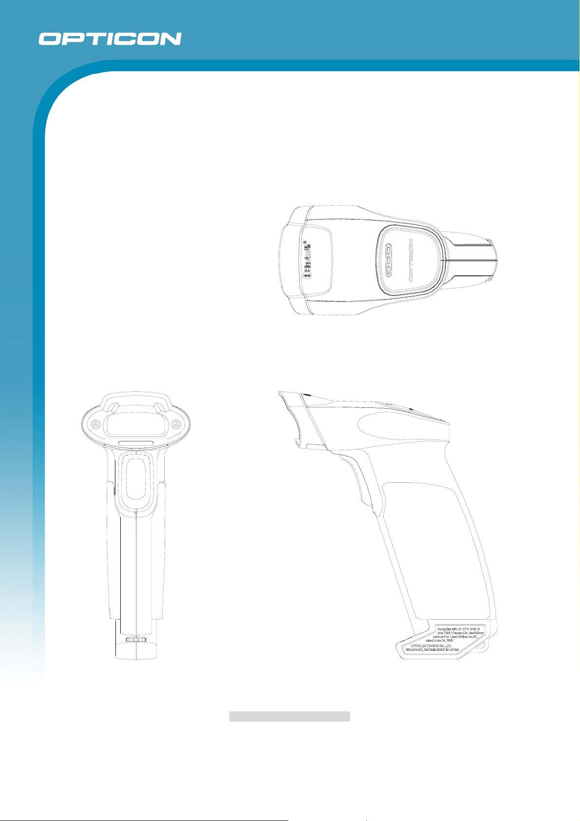
Dimensions: 137 × 56 x 113 (HWD mm, except protruding portion)
OPI-3301
Specifications Manual
Figure 16: Mechanical Drawing
33
 Loading...