

Page 1

OPR-3101
Simple Intruction manual
Wireless 1D Scanner
OPTOELECTRONICS Co.,Ltd.
Page 2

1. Package contents
1-1.OPR-3101
z Scanner body
<Accessory>
¾ Re-chargable battery pack
1-2.CRD-3101
z Communicating cradle body
<Accessory>
¾ AC adopter
¾ RS-232Ccable
1-3.CHG-3101
z Charging cradle body
<Accessory>
¾ AC adopter
1
Page 3
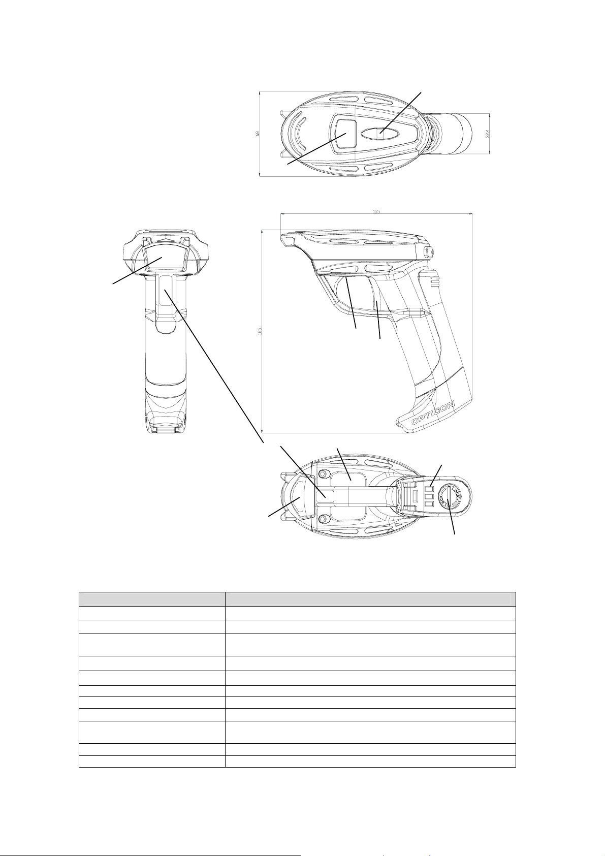
2.Detailed view
2-1. OPR-3101(Scanner)
①
⑥
③
⑧
②
⑪
⑨
⑦
⑩
④
OPR-3101 Detailed View
Name Function
1. Window Through the laser output and receive catoptric light from Barcode.
2. Trigger switch Scanning barcodes, connecting / disconnecting Bluetooth .
3. Indication Panel
4. Lock for Battery Lid For setting/detaching the battery pack.
5. Terminal for charging Receiving electric power supply through the feeding terminal of the cradle.
6. Hook Attach hand strap
7. Charging terminal Receiving electric power supply through the feeding terminal of the cradle.
8. Buzzer sound hole Show the status of success or failure of scanning and error occurrence.
9. Model name label
10. Serial number label Shows serial numbers
11. Laser caution label Cautionary note of laser
Chart 1.CHG-3101/CRD-3101 Name of parts and functions
Indicating how well the scanner reads, connection status of Bluetooth,
operation mode, remaining battery and charging status.
Shows the names of model, each specification, authentication text, logo and ID
numbers.
2
Page 4
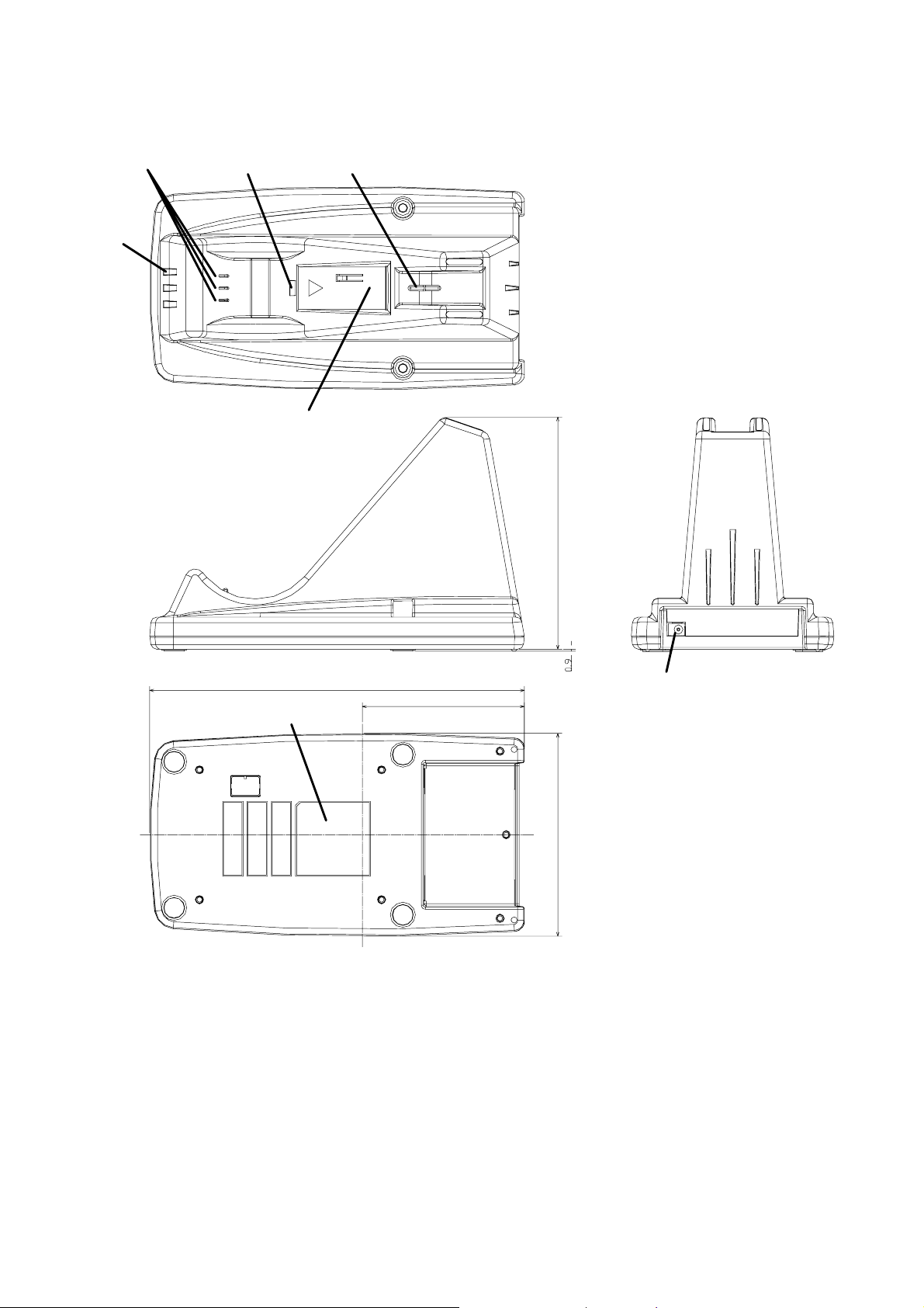
2-2. CHG-3101
④⑤⑥⑦
①
⑪
185
(80)
2 Detailed View
114.5
⑧
100
3
Page 5
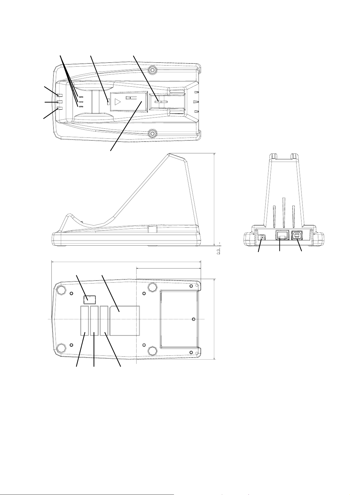
2-3. CRD-3101
①
②
③
④
⑤
⑦
⑥
114.5
185
⑧
(80)
⑨ ⑩
⑪⑫
100
⑬⑭⑮
3.CRD-3101 Detailed view
4
Page 6
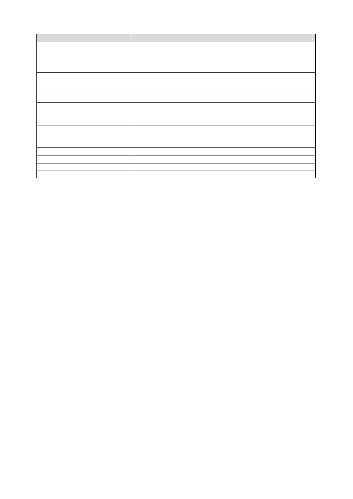
Name Function
2. Power supply LED LED Confirming power supply
2. Indication LED for wired data line Wired data line ( Between PC or Host system and Cradle)
3. Indication LED for wireless data
line
4. Terminal for power supply and
Detector
5. Charging LED LED confirming charging status of the battery pack
5. Battery charger Battery charger for the single battery pack
7. Scanner detection switch Detecting when the scanner body is put on the battery charger.
8. DC Jack
9. Plug-in phone jack Plug-in phone jack for RS-232C interface
10. USB connector Connector for USB interface
11. Model name label
12. Dip switch Switch for function settings *Please refer to chart 3 in the next page.
13. BD address label
14. Reserved For other lavel area1.
15. Reserved For other lavel area2.
LED confirming connection / disconnection of Bluetooth
Charging terminal for OPR-3101
A jack for charging AC adopter
Shows the names of model, each specification, authentication text, logo and
ID numbers.
Scanning it when connecting the scanner and cradle
Chart 2.CHG-3101/CRD-3101 Name of parts and functions
5
Page 7
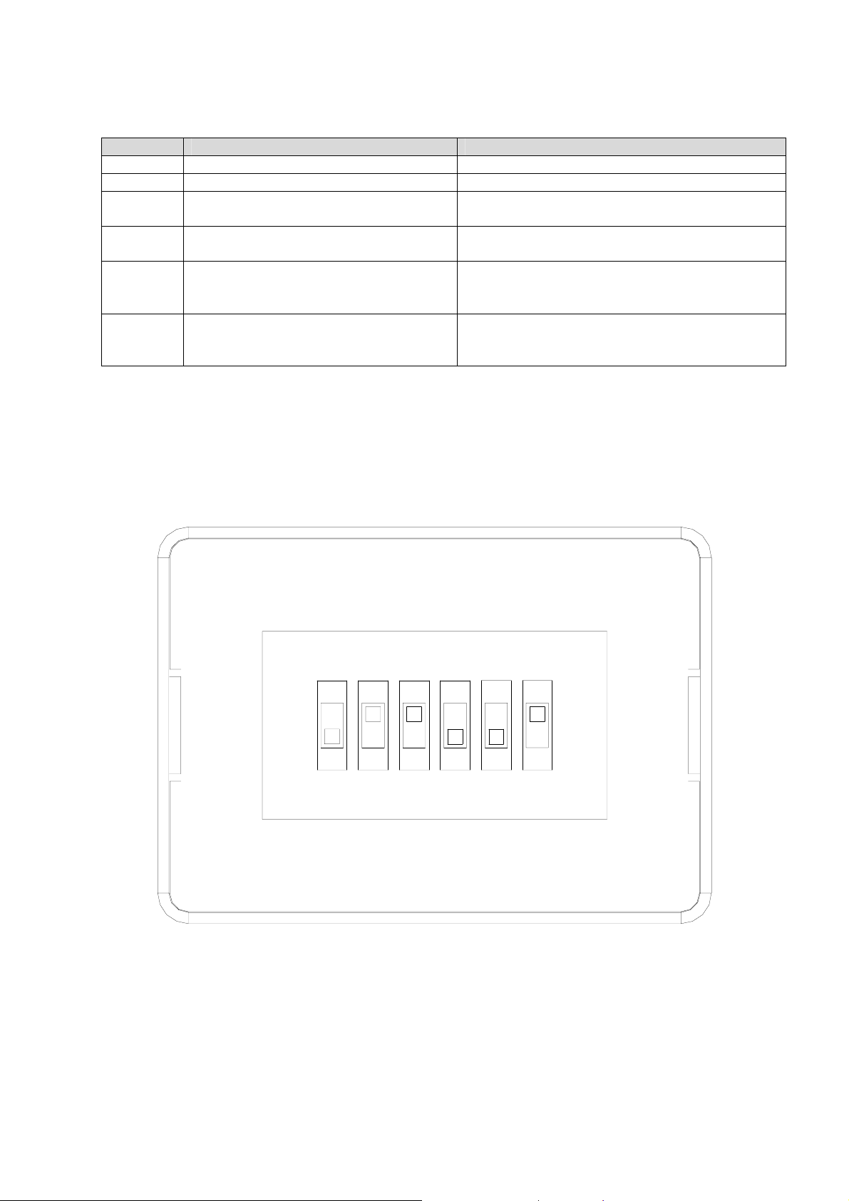
2-4. Dip switch settings
Dip switch located on the bottom of CRD-3101
Please follw the chart shown below
DIP SW FUNCTION REMARKS
SW1 Invalid Please use it with remaining power-off mode.
SW2 No security. Incwairi is effective. It can connect without authentication.
SW3 Opto protocol is invalid. It must disable SW3 in case of connect Bluetooth
SW4 The detection of the DTr signal is invalid. It is forced to choose RS232C. Switch it on when
SW5 Initialization (Shipment setting) Contains of settings place back to default settings when
SW6 Software down load mode Used when upgrading a firm ware through using
Chart3 Dip switch settings
※All switches are effective when they are power-on mode.
※SW2,3 and 4 are on, other SW are off when shipment setting.
devices except Scanner.
RS32C I/F is not with DTR signals/
switching it on.
When the default settings finish, please turn it on.
RS232C I/F. Please keep remaining power-off mode for
nomal use.
ON
123456
DIP switch l Detailed View
6
Page 8
3.For use
3-1.About the scanner
The charging battery pack is shipped without attaching the scanner.
Please attach the charging battery pack to the scanner.
As soon as attaching cradle or charger to the scanner, it will operate automatically ---Red LED, the status indicator
lights.
Also, when charging finishes, it becomes waiting mode.
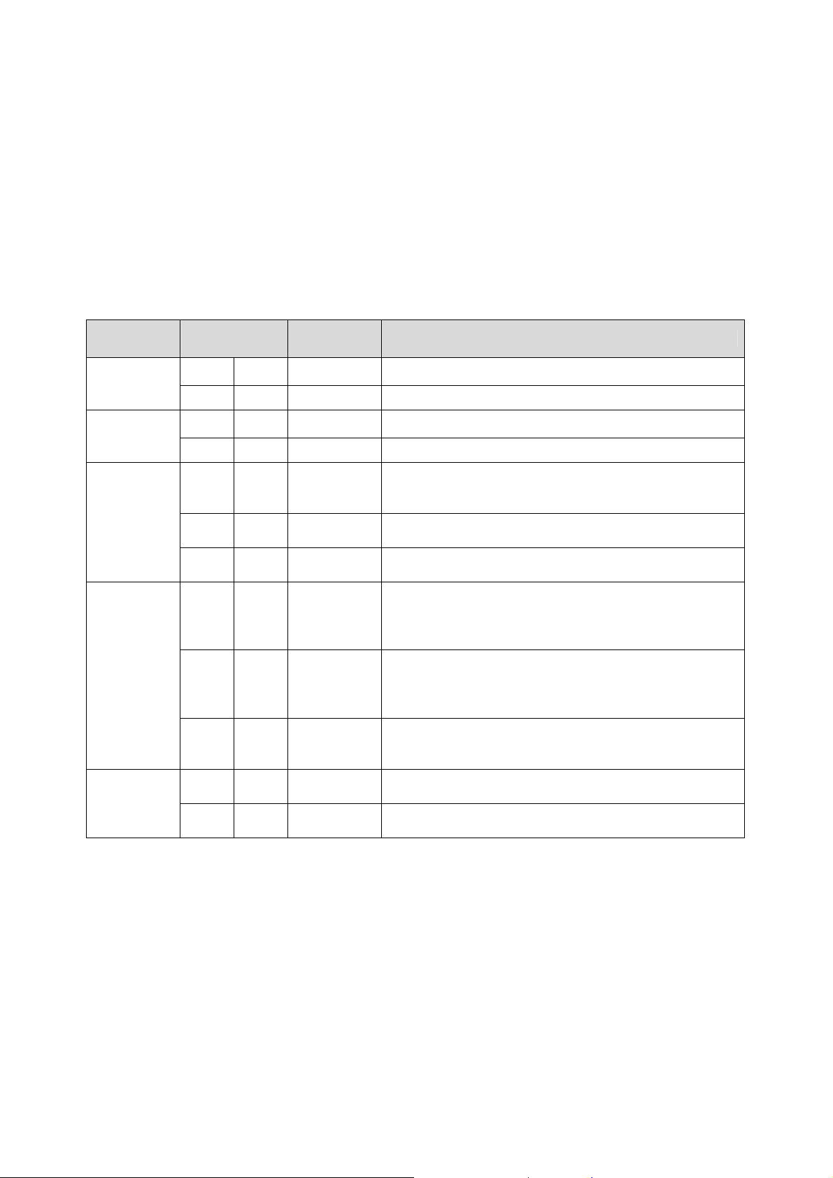
OPR-3101 Contains of status indicator LED Buzzer operation
Status LED Buzzer Remarks
At the start of
charging
In the middle
charging
Reading codes
Bluetooth
connection
Bluetooth
disconnection
red Light
green Light
red Light
green Light
blue Blink
red Blink
green Blink
Contin
blue
blue Light
red Light
red Light
red Light
uously
blink
4.OPR-3101 Contains of status indicator LED
-
-
-
-
2
tone-sound
Single tone
short sound
2-tone semilong sound
-
2tone
long sound
(Connecting
completed)
Single tone
semi-
long sound
2-tone
long sound
Single tone
long sound
It lights when the battery is not fully charged.
It lights when the battery is fully charged.
It lights when the battery is being charged.
It turns green when the battery charge is completed.
It behaves in case of reading Barcode and send that data to PC
or Host system.
Shows that it is a transmission failure.
Shows that it is storing data on the memory.
Shows that Bluetooth is in process of connecting.
Shows the connection of Bluetooth has been completed.
Shows Bluetooth connection failure
Shows Bluetooth disconnection
Shows
7
Page 9
3-2 About the charging cradle
CHG-3101 is specialized charger for OPR-3101.
CHG-3101 is not only able to charge the scanner, but also the charging battery pack.
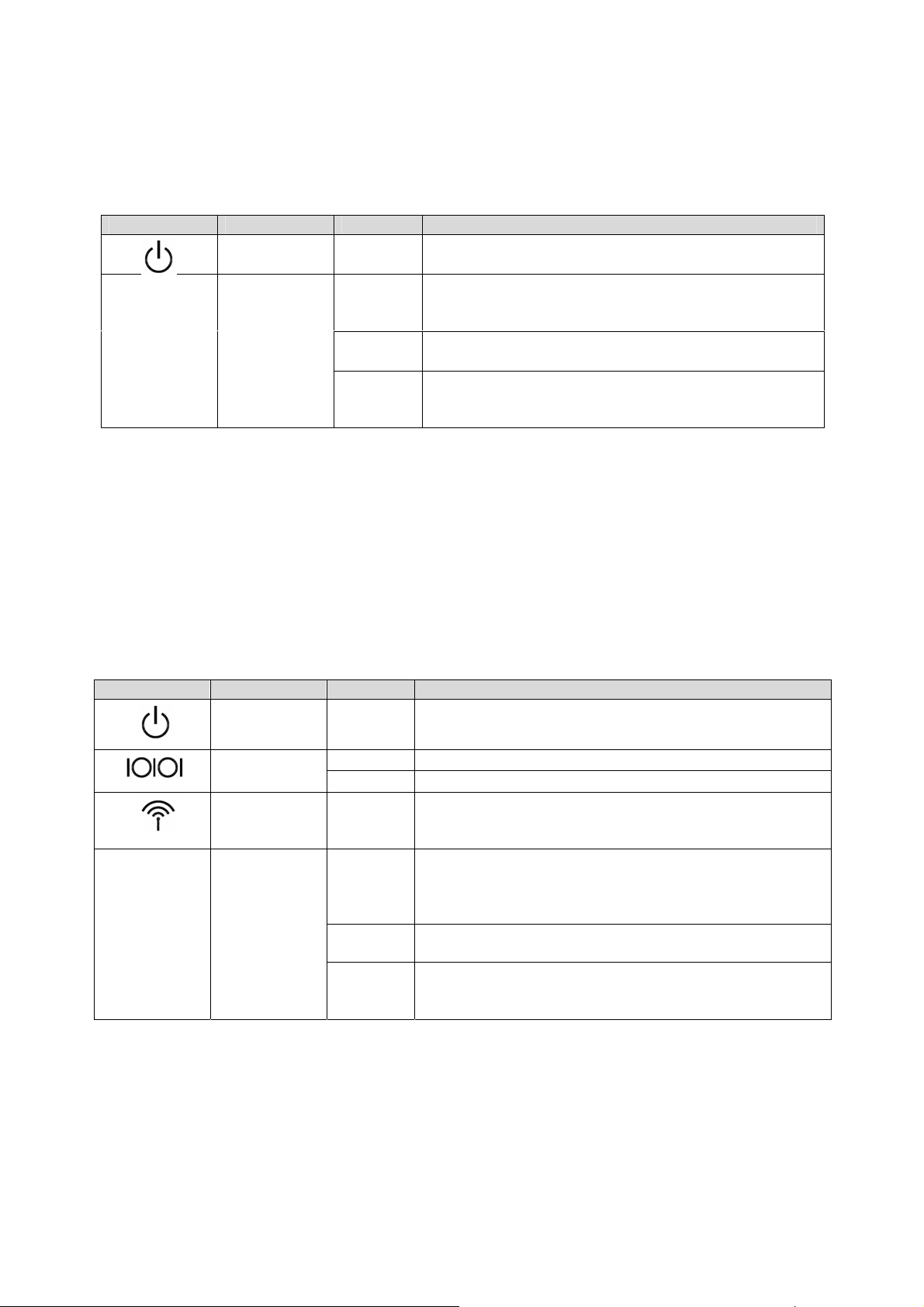
・LED display of the cradle
Code LED display color Remarks
―
3-3.About the communication cradle
Powrer Supply
LED
Charging
LED
red It lights when the battery is not fully charged.
Status LED when charging the battery pack with the cradle
red
green
green/red
It lights both when the battery is fully charged and being
charged in the beginning of charging,
It lights both when the battery is fully charged in the
beginning of charging and charging is completed.
Green LED lights and red LED blinks periodically.
It means either status that the battery pack is not attached or
set properly.
5.CHG-3101 Display status
CRD-3101is specialized communicating and charging cradle for OPR-3101.
CRD-3101 is not only able to charge the scanner, but also the charging battery pack.
It supports RS232C and USB interfaces. You can change them by transformation of cables.
It automatically recognizes the interfaces by observing the signal voltages.
*When both interfaces’ cables connects to the cradle, USB is prior to RS232C.
・Cradle LED display
Code LED display Color Remarks
Powrer Supply
LED
Communication
LED
Red It lights when the adopter is supplied with power.
Orange
Red (※)
Blue
Red
Green
green/red
―
Wireless LED
Charging
LED
It lights when it is sending and receiving data.
Disconnection of interface cable, host PC waiting
It lights when Bluetooth is connected,
It continuously blinks when Bluetooth is not connected.
The LED of the status display When charging the battery pack
with the cradle.
It lights both when the battery is fully charged and being charged
in the beginning of charging,
It lights both when the battery is fully charged in the beginning of
charging and charging is completed.
Green LED lights and red LED blinks periodically.
It means either status that the battery pack is not attached or set
properly.
6.CRD-3101 Display
※ It can’t detect when the host computer doesn’t support DTR signals..
・USB interface
USB 2.0 and full speed compliant specifications are supported,
Host computer recognize it as a HID device.
※ It’s capable of Hi - Power drive.
8
Page 10
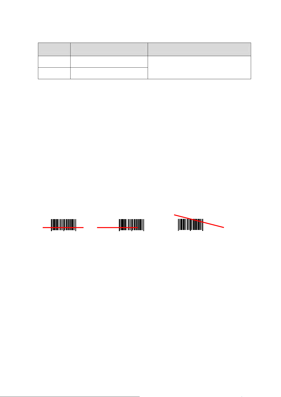
3-4.Charging time
As for CHG-3101/CRD-3101,l the battery connected to the cradle isn’t charged while the scanner is charged.
Spec. AC supplying mode Remarks
Approx. 5
hours
Approx. 10
hours
AC adopter drive
USB Hi-Power drive
The time needed for fully charging the empty
battery
7.Charging times of CRD-3101/CHG-3101
3-5.How to change the battery pack.
<Process>
1.Turn the screw of the bottom of the grip end anti clockwise with like a 1-Euro sized coin.
2.Open the lid and take out the old battery.(not to drop it.)
3.With checking for inner shape of Battery-box , insert new-BatteryPack faces Battery-terminal to Battery-box.
4.Close the lid and turn the screw clockwise.
4.Scanning barcodes
When pressing the button, laser beam is output from the reading window.
<○ Correct operation> <×Wrong operation > <×Wrong operation>
1 234567890128 1 234567890128
1 234567890128
9
Page 11

5.Connection of wireless communication system,
Wireless specifications
OPR3101 employs the Bluetooth (ver. 2.0 compliance) as a wireless interface.
It is capable of communicating with the devices with similar profiles owing to SSP correspondence.
■Data sending outputs
Class 2
■the structure of connection
1:1 (*1:N is not supported.)
■Operation mode when connecting
OPR3101 :Master
CRD3101 or PC and other connecting device :Slave
■Authentication and encryption
Authentication and encryption functions
※ When connecting with the communication cradle, authentication and encryption are effective. (In case of the
DIP switch 2,3 are power-off mode.
:Set with menu bar codes
※ There’s a need to match the settings of authentication and encryption in case of connecting other
devices.
■Communication distance
Approximately 10 meters
※ It varies depending on use environment.
■Connecting device settings
Choose the device to connect. The specialized cradle is set by default settings.
※ When setting it initial setting of SO, communicating cradle is set as a connecting device.
※ When set PC and other devices, the items as below are initialized.
・Authenticating connection settings :none
・ PIN code settings :none
・ Encryption settings :none
・ ACK/NAK control settings :non procedural
■BD address settings
Scan the BD address barcode written on the bottom of the scanner when connecting to CRD 3101.
It is to specify the other party. Please let us know BD address when connecting it to USB adopter and other
Bluetooth device so that we can offer you the BD address Barcode lavel. You can connect your Bluetooth device
scaning this lavel.
10
Page 12

■Connecting authentication settings
Settings for authentication settings
Please complete to enter the pin code with 30 seconds due to the time limit of the authentication
system.
※ Please set the PIN code before connecting with authentication.
※It may be a need to enter the pin code connecting with authentication. Then please enter the code again.
※You don’t need to enter the Pin code when connecting without authentications.
6.Connecting and disconnecting process
6-1.Connecting process
CRD-3101
1. Connect CRD-3101 to AC adopter and eitherRS232C I/F or USB cable.
2. Make sure the power supply LED, communicating LED, and wireless LED blinking.
3. Connect the cable to the host computer.
4. Make sure the communicating LED lights of after blinking.
5. Scan the BD address label.
6. As soon as blue LED blinks, connecting starts.
7. When connecting succeed, blue LED starts to light after blinking and the buzzer sounds.
※Please let us know when connecting it to USB, adopter and other Bluetooth device so that we can offer you the
BD address barcode.
※ Red LED blinks and buzzer beeps as a caution when connecting fails.
6-2.Disconnecting process
1.Disconect the communication as below.
・ Scan the label for disconnecting , [ +--DISC-+ ]
2. When disconnecting finishes, red LED lights and the buzzer beeps.
※Also you can disconnect the communication to read default setting menu Barcode [ SO] .
11
Page 13

7. Settings for shipping
The menu barcodes of scanner, communication and connection make settings easy. Therefore there are menu barcodes for
the default settings. Default setting <SO>menu is set before shipping.
Default Setting [SO] Readable codes
Transit
Code type Reading
and code
length
UPC-A ○ × ○ ○
UPC-A Add-on × × ○ ○
UPC-E ○ × ○ ○
UPC-E Add-on × × ○ ○
EAN-13 ○ × ○ ○
EAN-13 Add-on × × ○ ○
EAN-8 ○ × ○ ○
EAN-8 Add-on × × ○ ○
CODE-39 ○ × ○ ×
CODE-39 Trioptic ○ × ○ ×
NW-7(CODABAR) ○ × ○ ×
Industrial2of5 ○ × ○ ×
Interleaved2of5 ○ × ○ ×
CODE-93 ○ × × ○
CODE-128 ○ × × ○
EAN-128 × × × ○
S-Code ○ × ○ ×
MSI/Plessey ○ × ○CD1 ○CD1
UK/Plessey ○ × ○ ○
Telepen ○ × × ○
Matrix2of5 × × ○ ×
Chinese Post Matrix 2of5 × × ○ ×
IATA ○ × ○ ×
RSS-14 × × ○ ○
RSS-limited × × ○ ○
RSS-expanded × × ○ ○
PDF417 × ×
MicroPDF417 × ×
Transit and
CD
Calculate
and CD
- - -
- - -
Prefix
settings
-
-
-
-
-
-
-
-
-
-
-
-
-
-
-
-
-
-
-
-
-
-
-
-
-
-
Suffix
settings
Other transit items
CR
CR
CR
CR
CR
CR
CR
CR
CR Not transmit ST/SP
CR Not transmit ST/SP
CR Not transmit ST/SP
CR
CR
CR
CR
CR
CR
CR
CR
CR
CR
CR
CR
CR
CR
CR
CR
CR
12
Page 14
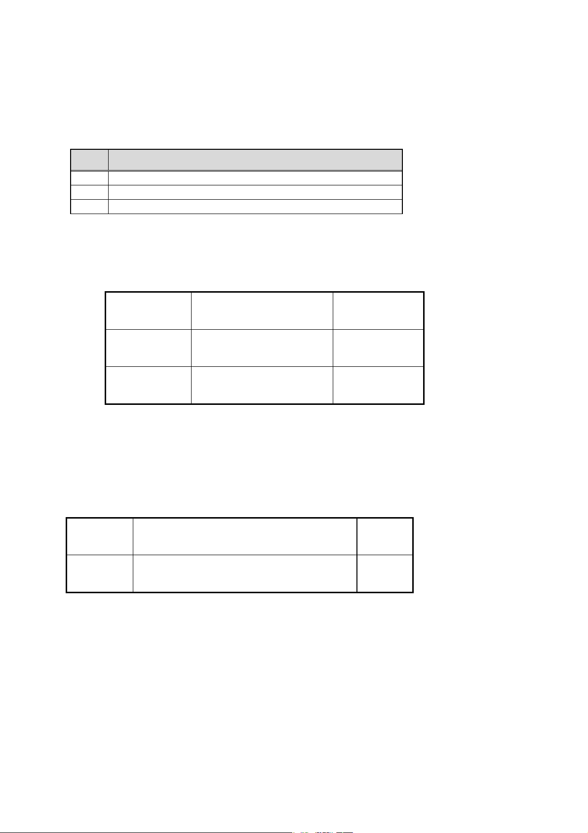
8.Menu barcodes for settings
Connection / disconnection settings for OPR3101
8-1.How to set
When scanning the same setting items, the item most recently scanned is effective.
Order Menu barcodes for scan
1
2
3
8-2.Default settings
The setting the place it back to the settings for shipping.
Scan the SET (zz)barcodes
Scan the optional barcodes.
Scan the END (zz)barcodes
Default
Set
End
_ZZ_
_SO_
_ZZ_
ZZ
SO
ZZ
8-3.Connection / disconnection control
Connection and disconnection can operate with the direct menu as below.
(No need to scan the END ZZ barcodes.)
Connect
Disconnect
※ It’s impossible to connect the other scanner to current cradle or Bluetooth device
_+-CONN-+_
_+-DISC-+_
without disconnecting operation.
+-CONN-+
+-DISC-+
13
Page 15
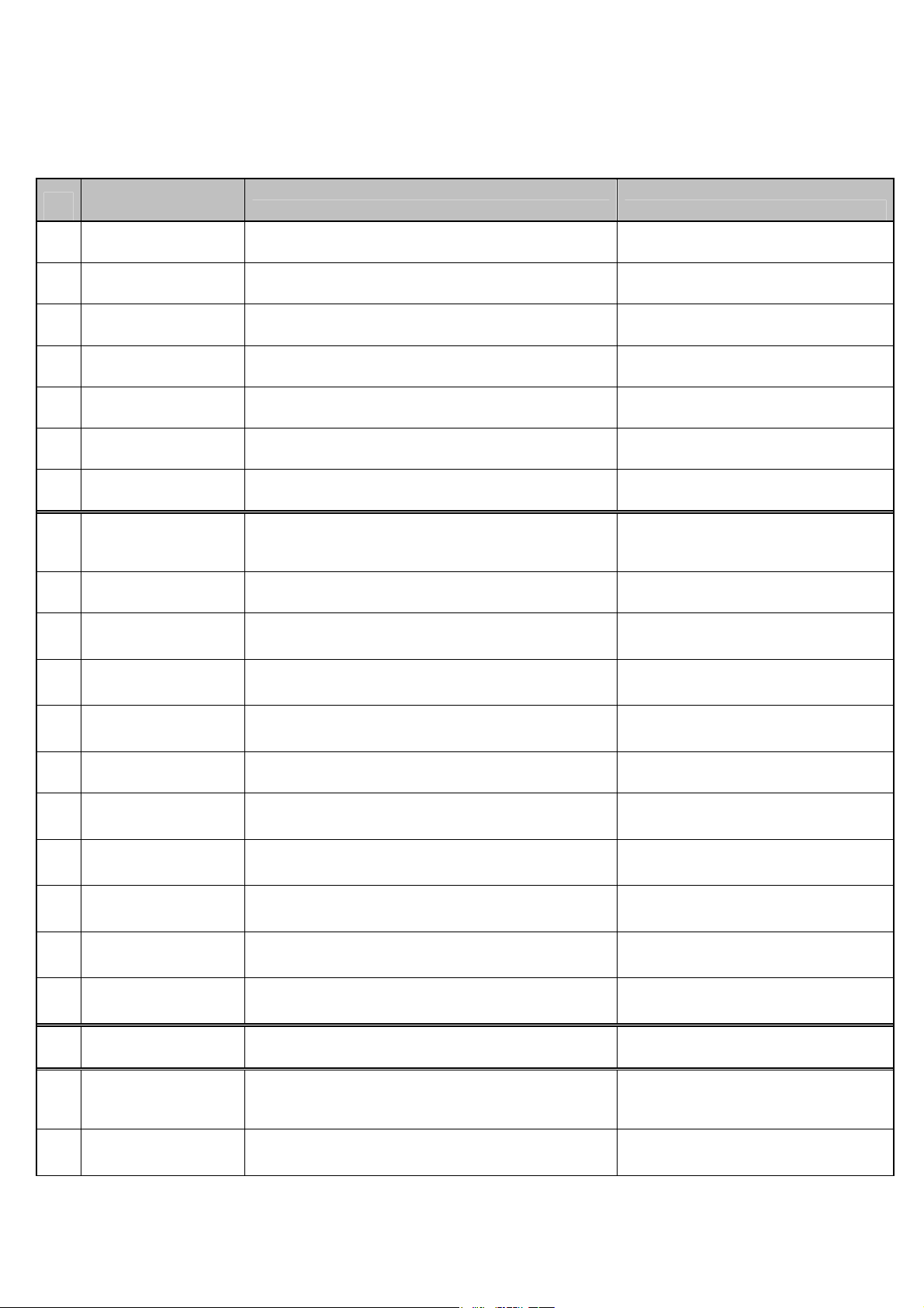
8-4.Control settings for wireless output measurement
The scanner keep sending and receiving status by setting the scanner with the items as below and that
make various wireless performance measurement easy.
COMMAND
NAME
BARCODE COMMAND
1
_+-RFPOWER-+_
2
_+-TXSTART-+_
3
_+-TXDATA1-+_
4
_+-TXDATA2-+_
5
_+-RXSTART-+_
6
_+-AFHTEST-+_
7
8
9
_ZZ_
_CH00_
_CH39_
_+-RFPOWER-+_
_+-TXSTART-+_
_+-TXDATA1-+_
_+-TXDATA2-+_
_+-RXSTART-+_
_+-AFHTEST-+_
_ZZ_
_CH00_
_CH39_
Inquiry
Non-Modulation
Non-Hop
Hop
Receive
AFH
Start/End of SetUp for
below COMMAND
Frequency LOW
Frequency MIDDLE
10
11
12
13
14
15
16
17
_CH78_
_PT00_
_PT01_
_PT02_
_PMAX_
_PMIN_
_ZZ_
_SO_
_CH78_
_PT00_
_PT01_
_PT02_
_PMAX_
_PMIN_
_ZZ_
_SO_
Frequency High
Packet Type DH5
Packet Type 2DH5
Packet Type 3DH5
Transmission Power Max
Transmission Power Min
Start/End of SetUp for
below COMMAND
Initial Setting
14
Page 16

※Command numbers 1 to 6 can scan directly without settings by start/end ZZ codes. After
scanning these numbers , the commands keep operating as long as the red and green LED
blink.
Press the trigger button to release the command.
※There’s a need to scan start/end ZZ codes concerning command 8 to 15.
※ For example, you can confirm the RF output with read few RF-test Barcode combination.
Confirm the Non-Modulation, Non-Hop and AHF with under condition.
Data Packet type : 2DH5 , Frequency : Low , Maximum RF ou
1 「ZZ」→「_CH00_」→「_PT01_」→「_PMAX_」→「ZZ」
2 「_+-TXSTART-+_」 :Keep Non-Modutation mode after read this Barcode and during
LED-flushing.
3 Press Trigger-Switch to release Non-modulation mode. Turn off LED after press
Trigger-Switch.
4 「_+-TXDATA1-+_」 : Under the step1 condition , for confirmation Non-Hop mode
by reading this Barcode. Keep to output Non-hop mode
during LED flushing after read this Barcode.
5. To release Non-hop mode , do operate step3
6. Under the step1 condition , for confirmation AFH mode by reading this Barcode.
Keep to output AFH mode during LED flushing after read this Barcode.
7. To release AFH mode, do operate step3.
15
 Loading...