

Page 1
PX-25 SS08068
Master Specifications
2D Data Collector with Bluetooth
Product Name PX-25
Specification No SS08068
Edition Initial release
Date of Publication Nov 5,2008
Original Doc. No. SS08059
OPTOELECTRONICS Co., Ltd.
4-12-17 Tsukagoshi,
Warabi-shi, Saitama,
335-0002 Japan
TEL: 81+(0)48-446-1183
FAX: 81+(0)48-446-1184
Page 2
PX-25 SS08068
Revision History
Specification No.: SS08068
Product name : PX-25
Revision Date Section Description of Changes
Initial release 2008/11/5 - -
1
Page 3

PX-25 SS08068
Table of Contents
1. Abstract .............................................................................................................................1
2. Overview ...........................................................................................................................1
3. Physical Features..............................................................................................................2
4. Basic Specifications...........................................................................................................4
5. Optical Specifications ........................................................................................................6
6. Technical Specifications ....................................................................................................6
7. Aiming .............................................................................................................................10
8. Bluetooth ......................................................................................................................... 11
9. Serial Label .....................................................................................................................12
10. Packaging Specifications...............................................................................................13
11. Durability........................................................................................................................15
12. Warranty........................................................................................................................ 16
13. Regulatory Compliance ................................................................................................. 17
14. RoHS .............................................................................................................................18
15. Precautions.................................................................................................................... 18
2
Page 4

PX-25 SS08068
1. Abstract
This manual provides specifications for the data collector with an embedded 2D data collector which
offers Bluetooth, PX-25.
2. Overview
・ PX-25 consists of a 130 million pixel-CMOS sensor and a wide angle lens with Bluetooth.
・ Scanned data is output via Bluetooth interface.
・ Bluetooth and IrDA (for the communication with the dedicated cradle) interface enables data
communication with higher models.
・ This product is compliant with RoHS.
2.1. Product / Model Name
Product name: PX-25
2.2. Features of PX-25
・ Compact and handy design
・ The data collector is able to read 2D barcodes.
・ Stored data is sent to the recipient through Bluetooth interface. On the other hand, IrDA can
communicate with host PC via the dedicated cradle.
・ Embedded Bluetooth is compliant to version 1.2 and has installed profile.
・ PX-25 can operate for a long time with a dedicated built-in lithium-ion battery (1880mh).
・ Unit is charged when placing it on the dedicated cradle.
(To directly connect the dedicated adapter to PX-25 can also charge the unit.)
1
Page 5

PX-25 SS08068
3. Physical Features
3.1. Dimensions
Figure1: Dimensions
3.2. Weight
Max. 182g (including lithium-ion battery pack)
2
Page 6
PX-25 SS08068
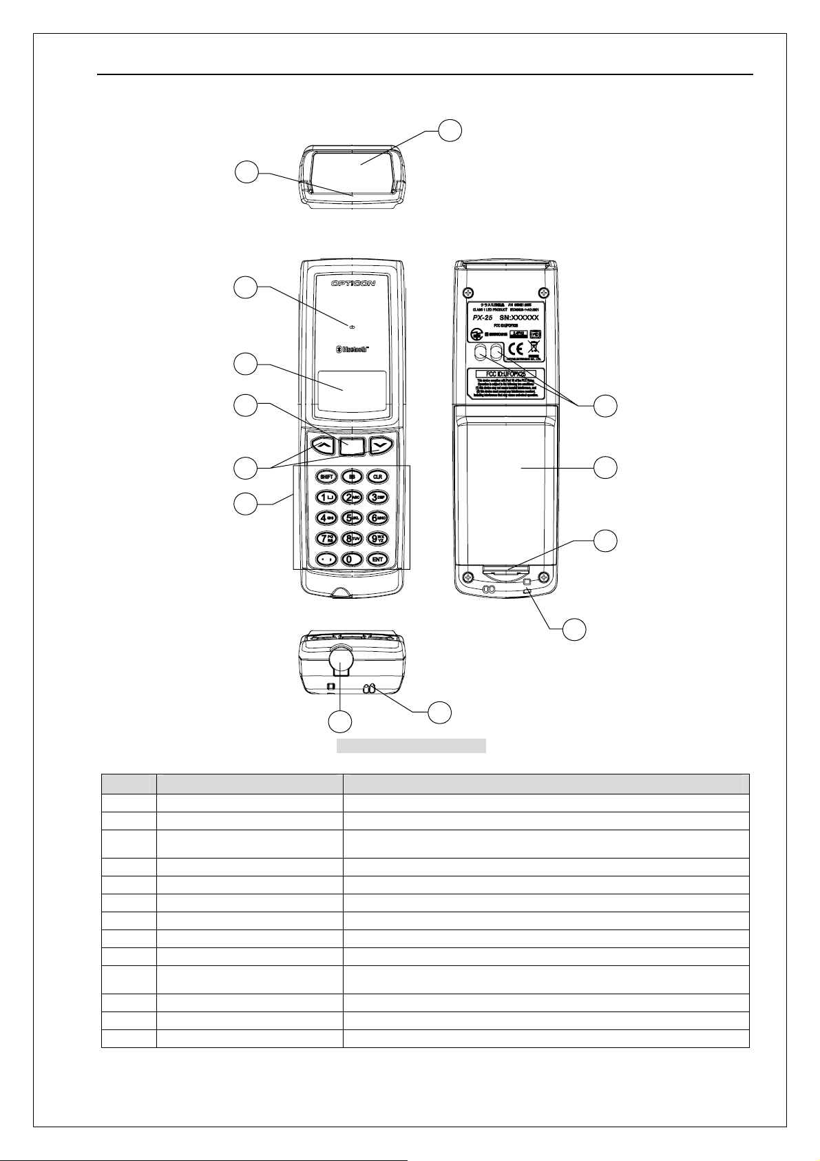
3.3. Physical Features
1
2
3
4
5
6
7
8
9
10
11
12
13
Figure2: Physical features
No. Item Specification
1. Scanning window LED light for scanning barcode is emitted from the window.
2. IrDA Use for the communication with dedicated cradle
3. LED
4. LCD Indicates scanned barcodes and operational items
5. Trigger key Press when scanning barcodes
6. Up / Down keys Used when selecting items from a menu.
7. 10 operational keys Used for numerical, “ENTER”, decimal point input.
8. DC Jack Used for the dedicated power supply
9. Speaker
10. Terminals
11. Battery cover Remove when replacing the rechargeable battery
12. Battery cover lock Used to lock / open the battery cover
13. Strap hole Hole for attaching a hand strap
To notify the status of barcode scanning, Bluetooth communication, and
warnings so on.
Used to charge a lithium-ion battery of a unit when placing the unit on
the dedicated terminal
3
Page 7
PX-25 SS08068
4. Basic Specifications
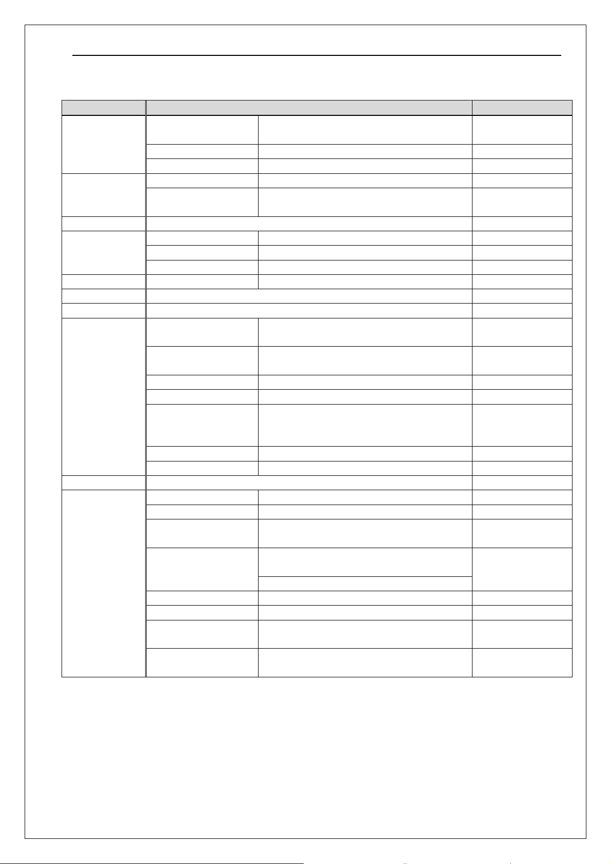
Item Specification Remark
CPU 32Bit RISC Micro computer (ARM7 Core)
Control section
Memory
OS μITRON
Display section
Operating section Key type 18 keys
Indication LED Tri-colored emitting elements (red/green/blue)
Buzzer Adjustable volume/tone
Bluetooth
IrDA IrDA Ver1.2(physical layer compliant) Baud rate: Maximum 115.2Kbps
Power supply
Embedded ROM 256Kbyte + 16Kbyte (for DATA)
Embedded RAM 64Kbyte
FROM(NOR) 4Mbyte (User area: about 1Mbyte) OS/AP
SRAM
LCD semi-transmissive LCD
Number of dots 112×64 dots
Back light Available
Specification Bluetooth Ver1.2
Installed profile SPP
Frequency 2402MHz to 2480MHz
Transmission power Class 2
Communication range Perspective 10m
Baud rate 115.2kbps
Antenna 1/4λ (surface mounted)
Main power Lithium-ion secondary battery 1880mAh
Regular voltage 3.7V
How to charge With a dedicated AC adapter or cradle
Charging time
Scanning frequency Over 30,000 times *2
Up-time 25 hours *3
Backup battery
Data holding time 72 hours or less
2Mbyte (User area : about 480kbyte)
4Mbyte (Option)
With a dedicated AC adapter: about 4 hours and
half
With a dedicated cradle: about 7 hours and half
MS (Manganeese Silicon) lithium secondary
battery 3.4mAh
Produced by ST
Micro
for WORK/DATA
HCI module produced
by Kyocera
Stack produced by
iAnywhere
Communication
range may differ due
to the environments.
With a rubber pad for
the jack part
*1
Without full discharge
After main battery has
been discharged.
4
Page 8
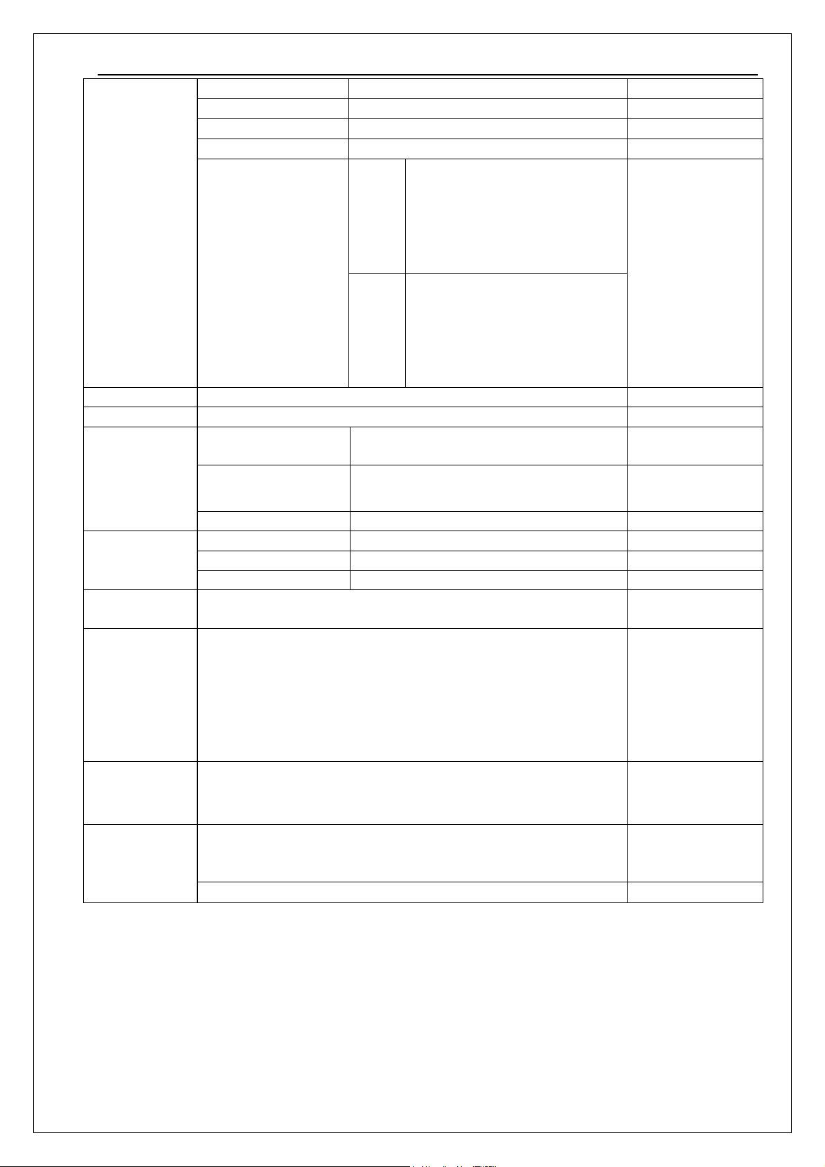
PX-25 SS08068
Scanning method CMOS area sensor (black/white) MSI-1001
Effective pixels 1.3 million pixels
Light source Red LED
Scanning angle range Horizontal: 47° Vertical: 37.5°
PDF417, Micro PDF417, QR Code,
Micro QR Code, Data Matrix (ECC
2D barcode
scanning section
(R-3D, MDI-1001
specification)
Dimensions
Weight Max. 132g (including lithium-ion battery pack)
Conditions
Drop test *4
Dust and drip
proof
Regulatory
compliance
Accessories
Option
*1 The dedicated AC adapter is for charging use only. Please detach it when using the product.
*2 when scanning a barcode once per second at room temperature + frequency of connecting to Bluetooth.
*3 when scanning a barcode twice in 10 seconds at room temperature + frequency of connecting to Bluetooth.
*4 Shock resistance
Conditions of the shock resistance test are:
・ Does not count scratches or whitening on a surface as a malfunction.
・ Shock resistance is approved when no malfunction occurs after the test.
・ Shock resistance is approved if the battery cover is not unhooked after the test
Supported symbology
140×44×26mm
Operation temperature
and humidity
Storage temperature and
humidity
Charging temperature 0 to 40°C
Frequency
Height 150cm
Floor Concrete
IP42
Illumination LED safety:
JIS C 6802:2005 class 1
IEC 60825-1+A2:2001 Class 1
VCCI Class B
Radio Law 38-24-1CE
CE Marking, FCC
Bluetooth logo certification
Dedicated lithium-ion battery (1880mAh)
Hand strap
User’s manual
Dedicated cradle
Dedicated AC adapter [6V/2000mA] For charging
2D
1D
-10°C to 40°C
20%RH to 85%RH
-20°C to 60°C
20%RH~85%RH
6sides, 3cycles
0-140, ECC200), Maxi
Code(mode0~5), Aztec Code,
Composite Code Intelligent Mail
Barcode
WPC (EAN, JAN, UPC-A/UPC-E),
Industrial 2of5, IATA, Interleaved
2of5,
NW-7(CODABAR), CODE-39,
CODE-93, CODE-128, MSI/Plessey,
RSS Code
No frost, no
condensation
No frost, no
condensation
For IrDA
communication /
charging
5
Page 9
PX-25 SS08068
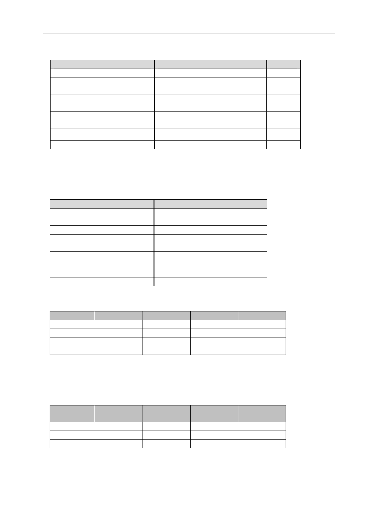
5. Optical Specifications
Item Specifications Unit
Scanning method CMOS area sensor (black/white) -
Scanning speed 30 fps
Effective pixels
Aiming LED center wave length
(green LED x 2)
Illumination LED center wave length
(Red LED x 4)
Scan angle Horizontal: 47 Vertical: 37.5 °
Focal plane 85 mm
1280(H)×1024(V)
527 nm
630 nm
Pixel
6. Technical Specifications
The conditions for technical specifications are as follows, unless otherwise specified in each section.
Conditions
Item Conditions
Ambient temperature and humidity Room temperature and humidity
Ambient light 1,000 to 1,500 lx (barcode surface)
Light source 3 wave lengths inverter fluorescent
Angles
Curvature R = ∞
Power supply voltage 3.3V
Decoding test Approve the performance when decoding is
Barcode sample As specified below
<Bar Code>
Resolution Barcode PCS Size [mm] Digit
0.254mm Code 39 0.9 14×10 2
0.1mm Code 39 0.9 11×10 4
0.26mm JAN-13 0.9 25×19 13
0.26 mm JAN- 8 0.9 17.5×15.5 8
Barcode sample: OPTOELECTRONICS test sample – Resolution = 0.127mm
or
OPTOELECTRONICS test sample – Resolution = 0.26mm
N:W ratio = 1:2.5
<PDF417>
Resolution Error correction PCS Size [mm]
0.339mm Level-4 0.9 35×22 17
0.254mm Level-4 0.9 26×16 17
0.127mm Level-4 0.9 13×8 17
Barcodes printed by a normal printer – aspect ratio = 3 : 1
α=0° β=+15° γ=0°
successful in 70% of ten tests performed.
Number of
character
6
Page 10
PX-25 SS08068
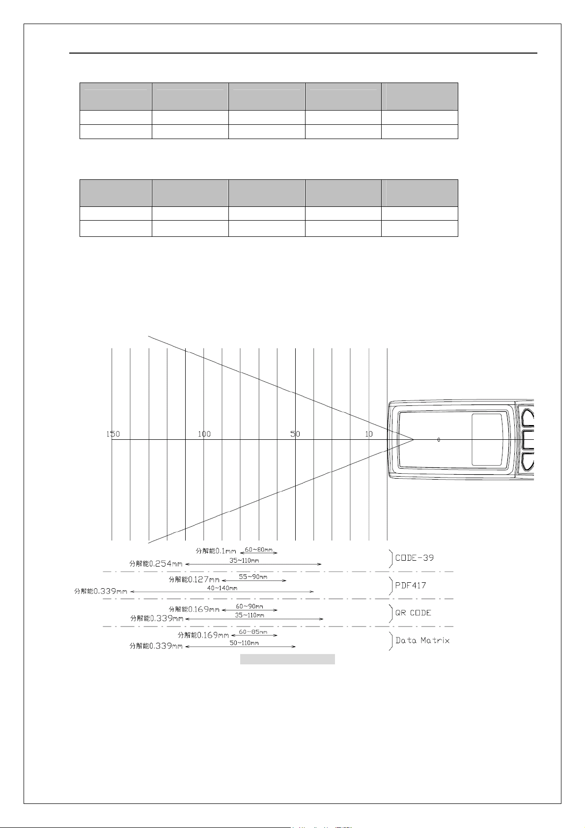
<QR Code (Model-2)>
Resolution Error correction PCS Size [mm]
0.339mm M 0.9 10×10 44
0.169mm M 0.9 5×5 44
Barcodes printed by a normal printer
Number of
character
<Data Matrix>
Resolution Error correction PCS Size [mm]
0.339mm ECC200 0.9
0.169mm ECC200 0.9
Barcodes printed by a normal printer
*As for the size of each barcode, quiet zone length is excluded.
8×8
4×4
Number of
character
40
40
6.1. Physical Features
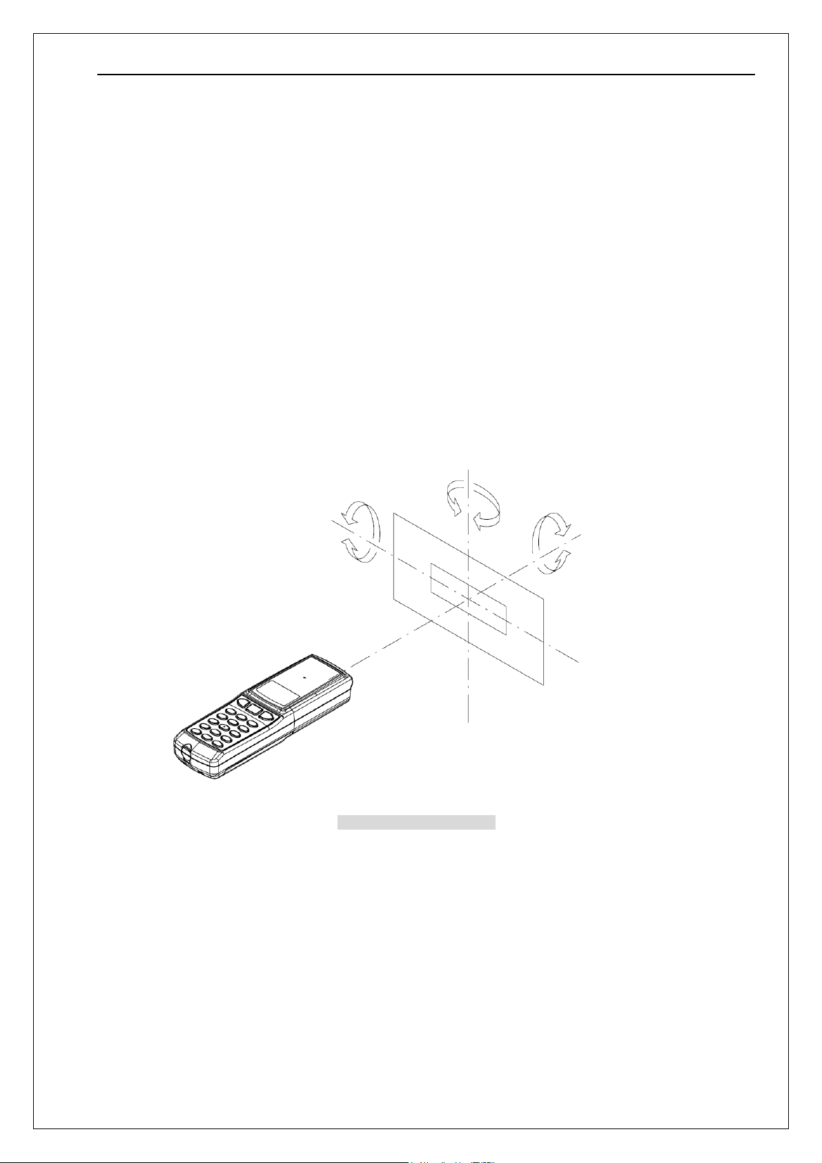
Figures of scanning field shows the distance from the focal plane of the data collector.
Figure3: Scanning field
7
Page 11
PX-25 SS08068
6.2. Printed Contrast Signal
0.45 (MRD 32%) or higher (over 70% of reflectivity of space and )
*Scanning performance may decline if dirt or scratches mar the optical window. Keep the optical
window clean.
6.3. Pitch, skew and tilt
Pitch angle: α = ±50°
Skew angle β = ±60
Tilt angle: γ = 360
Conditions:
Barcode sample: CODE-39, PDF417, Resolution 0.254mm, PCS0.9 as specified in the section 6.
Distance: 63mm from the focal plane of the data collector
Curvature: R=∞
°
°
(For pitch/tilt angles, skew angle β = +15°)
Figure4: Pitch, skew and tilt
*When scanning symbologies printed on highly glazed paper such as glossy paper or card case, scanning
performance of this data collector may decline due to the specular reflection of LEDs. In such cases,
adjust scanning angle by incline the data collector to 15 degrees toward the skew direction to improve
scanning performance. When turning off the lighting LED, it may decline the scanning performance unless
the ambient light is 1000 lx or higher. Also, the light or reflection light caught by the camera may decline
scanning performance, when using codes on the above described paper.
8
Page 12
PX-25 SS08068
6.4. Curvature
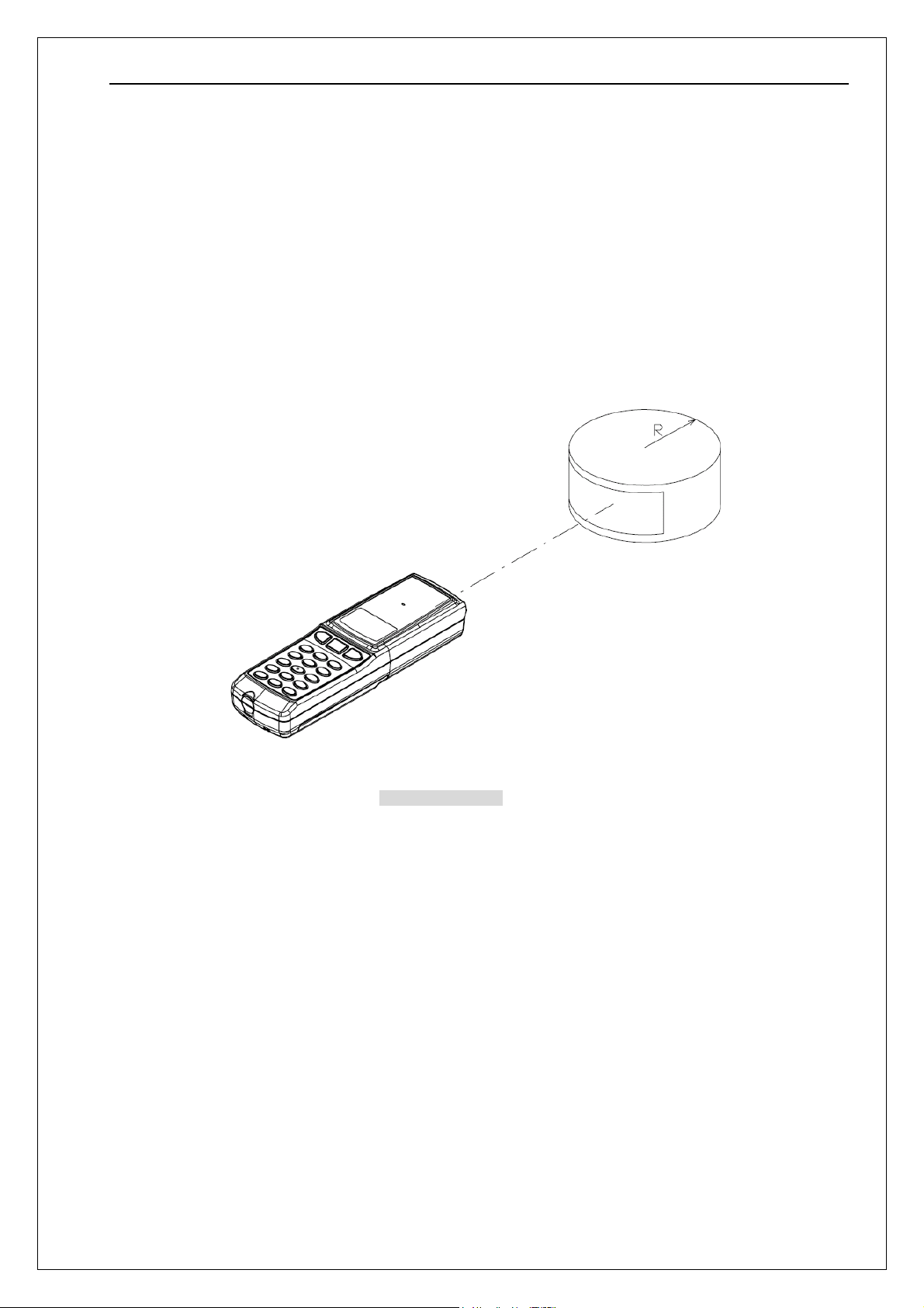
With 8-digit JAN barcode, decoding performance is guaranteed when R≥15 mm.
With 13-digit JAN barcode, decoding performance is guaranteed when R≥20 mm.
Conditions
Barcode sample: CODE-39, PDF417, Resolution 0.254mm, PCS0.9 as specified in the section 6.
Distance: 63mm from the focal plane of the data collector
Curvature: R=∞
(For pitch/tilt angles, skew angle β = +15°)
Figure5: Curvature
9
Page 13
PX-25 SS08068
g
w
7. Aiming
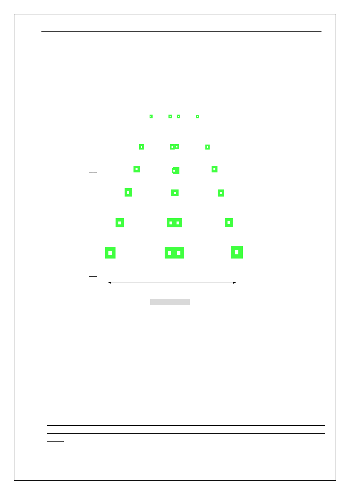
During scan operation, the Green LED patterns as shown below will be exposed.
It is called as “Aiming” and is superimposed on the illuminated scan field.
7.1. Aiming Pattern
* Aiming is a guide to support the scanning operation. Note that an aiming pattern neither
Unit: mm
[単位:mm]
Distance from the focal plane
30
80
130
180
(水平方向画角)
Horizontal an
le of vie
Figure6: Aiming
indicate exact sannable width nor distance between a data collector and a barcode.
7.2. How to Use Aiming
・ A recommended aiming point is where two central LED light patterns (green and
square-shaped) overlap together.
・ To scan a barcode within a width of aiming range, make sure that two central LED light
patterns overlap together. Then locate the center of the overlapped LED light pattern on the
center of the barcode.
・ To scan a barcode wider than a width of aiming range, aim the barcode from farther point.
Make sure that the barcode is in between two LED light patterns at right and left ends.
* The scanning performance may decline due to the specular reflection when the symbology is printed
on certain types of materials. In such cases, incline the data collector at 15 degrees to adjust scanning
angle.
10
Page 14

PX-25 SS08068
8. Bluetooth
8.1. Installed Profile
Bluetooth wireless communication is used as a wireless interface.
8.2. Communication Configuration
1 to 1 (One data collector to one host system)
8.3. Operating Mode While Connected to the Host System
Master mode
8.4. Security Mode
Authentication enabled
8.5. Encryption
Encryption enabled
11
Page 15
PX-25 SS08068
9. Serial Label
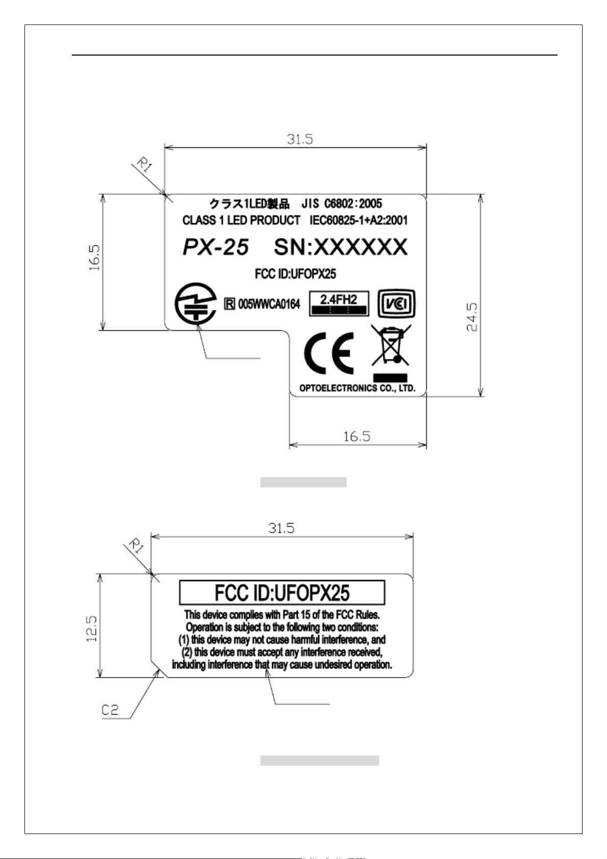
The labels shown below are affixed to the data collector.
Text: black
Figure7: Serial label
Text: black
Figure8: FCC caution label
12
Page 16
PX-25 SS08068
10. Packaging Specifications
10.1. Individual Packaging Specification
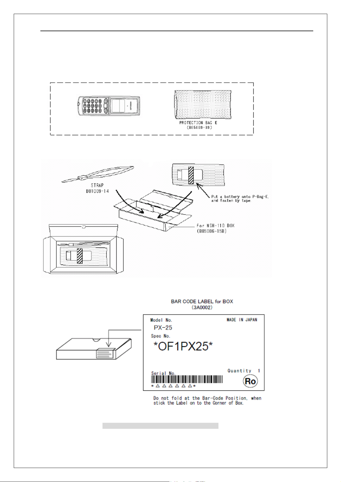
Put the data collector in a protective foam bag and place it in an individual packing box.
Size of the package (after assembly) 255(W) × 120(D) × 105(H) mm
Figure9: Individual packaging specification (T.B.D )
13
Page 17
PX-25 SS08068
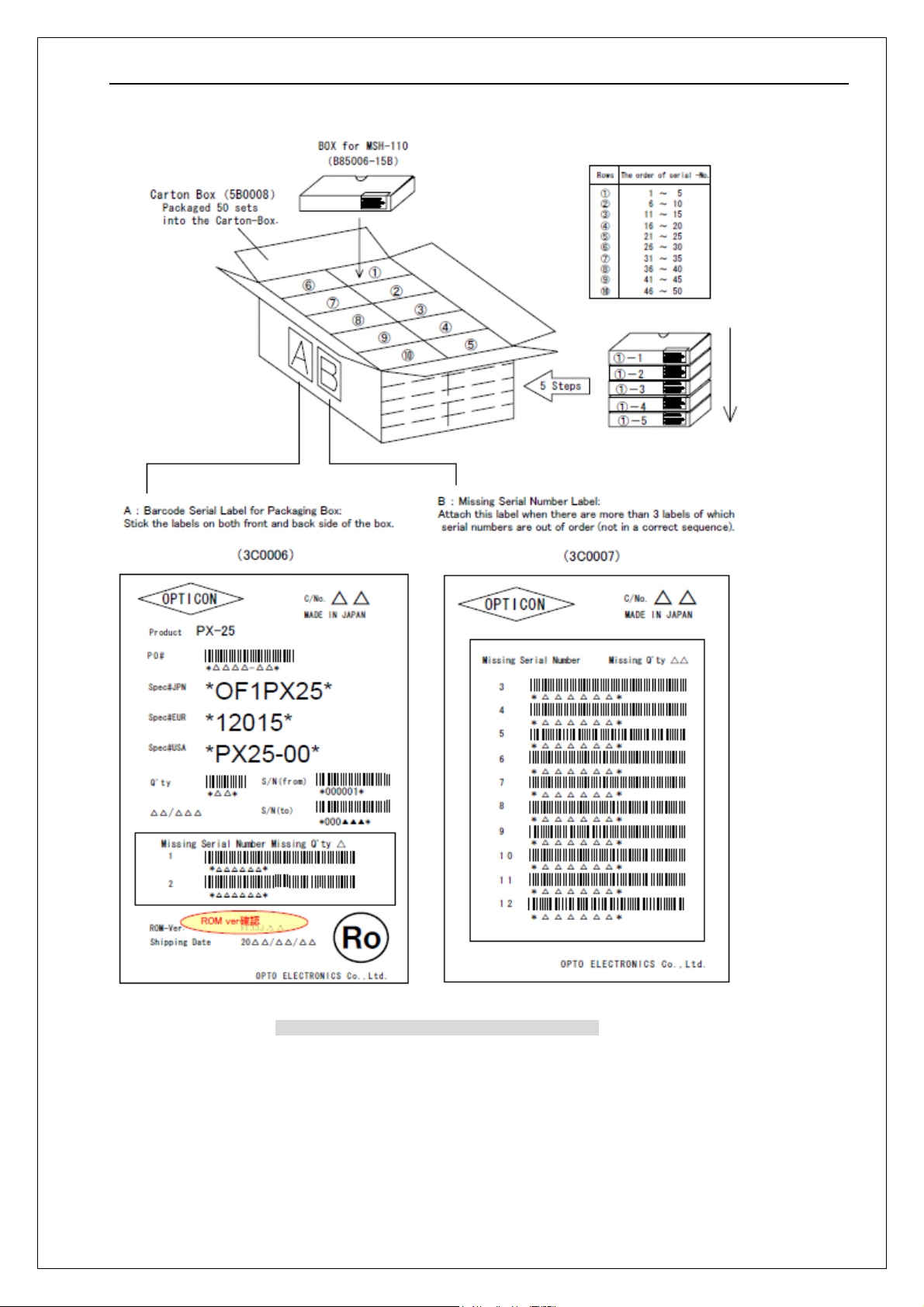
10.2. Collective Packaging Specification
Figure10: Collective packaging specification (T.B.D )
Note: The “RO” mark labeled on the package tray or package box guarantees that the applicable product
has passed our test of RoHS restrictions compliance (the restriction of the use of certain hazardous
substances in electrical and electronic equipment, 2002/95 EC). However, this document does not have
any legal weight in the European Union.
14
Page 18
PX-25 SS08068
11. Durability
11.1. Ambient Light Immunity
Decoding performance is guaranteed when the range of illumination on a barcode surface is
between zero and the following values:
Incandescent light 10,000 lx
Fluorescent light 10,000 lx
Sunlight 1000,000 lx
Conditions
Barcode sample: CODE-39, Resolution 0.254mm, PCS0.9 as specified in the section 6.
Distance: 63mm from the focal plane of the data collector
Angles: α = ±50°, β = ±60°, γ = 360°
Curvature: R=∞
Direct light or specular reflection from a light source should be prevented from entering the
*
acceptance area.
11.2. Dust and Drip Proof
IP42
11.3. Vibration Strength (without packaging)
No malfunction occurred after the following test.
Vibration test: Increase the frequency of the vibration from 10Hz to 100 Hz with accelerated
velocity 19.6m2/s (2G) for 60 minutes in non-operating state
Repeat this routine in each X, Y, Z direction once for 60 minutes each.
11.4. Vibration Strength (with individual packaging)
No malfunction occurred after the following test.
Vibration test: Increase the frequency of the vibration from 10Hz to 100 Hz with accelerated
velocity 19.6m
Repeat this routine in each X, Y, Z direction once for 60 minutes each.
11.5. Drop Test (without packaging)
No malfunction occurred after the following test.
Drop test: Drop the data collector from a height of 150cm onto a concrete floor.
(Three times in each of 6 angles)
11.6. Drop Test (with individual packaging)
No malfunction occurred after the following test.
Drop test: Drop an individually packaged data collector from a height of 70cm onto a concrete
floor once on its 1 corner, 3edges, and 6 sides. (10 total drop tests)
2
/s (2G) for 60 minutes in individually packaged state.
15
Page 19
PX-25 SS08068
11.7. Static Electricity
Air discharge: ±10 kV max. (No malfunction)
±15 kV max. (No destruction)
Contact discharge: ±6 kV max. (No malfunction)
±10 kV max. (No destruction)
Measurement environment: Use electrostatic testing device compliant with IEC 61000-4-2.
Discharge resistance: 330 Ω
Capacitor charging: 150 pF
11.8. Reliability
MTBF (Mean Time Between Failures): 5 years
Life cycle of the CMOS camera: 150,000 hours
12. Warranty
12.1. Warranty Period
Optoelectronics Co., Ltd. (hereinafter ‘Optoelectronics’) warrants that this product is free of
defects and malfunctions for a period of 12 (twelve) months beginning on the last day of the
month in which it is shipped. Optoelectronics will repair product defects or malfunctions that
arise in the course of normal usage during the twelve-month warranty period free of charge.
Any repair or replacement of the product after the foregoing warranty period will be charged at
regular rates.
Repair or replacement of the product due to defects or malfunctions that arise as a result of
customer mishandling will be charged at regular rates, even during the foregoing warranty
period.
12.2. Delivery
Products for maintenance or repair shall be sent back to Optoelectronics. The sender is
responsible for all shipping costs.
12.3. Repair Timeframe
Repaired products shall be shipped back to the customer within 20 days after acceptance by
OPTOELECTRONICS. However, the time needed for the repair of products with early failures
need to be separately discussed with Optoelectronics.
Expedited repairs may be available, subject to terms agreed to by OPTOELECTRONICS and
the customer.
12.4. Maintenance Period
The maintenance period of this product is 5 years after its shipment.
OPTOELECTRONICS may discontinue maintenance for this product during the 5-year
maintenance period if a satisfactory replacement product or maintenance solution is agreed
to.
12.5. Others
Any additional warranty issues must be discussed with OPTOELECTRONICS on a
case-by-case basis.
16
Page 20
PX-25 SS08068
13. Regulatory Compliance
13.1. LED Safety (for illumination)
・IEC60825-1+A2:2001 Class 1
・JIS C 6802:2005 Class 1
13.2. Product Safety
・IEC60950-1
・EN60950-1
13.3. EMC
・EN55024
・VCCI Class B
・FCC Part 15 Subpart B Class B
・FCC Part 15 Subpart C
FCC Part15 subpart B&C Statement
This device complies with part 15 of the FCC Rules. Operation is
subject to the following two conditions : ( 1 ) this device may not cause
harmful interference, and ( 2 ) this device must accept any interference
received, including interference that may cause undesired operation.
VCCI Class B
This is a Class B product, to be used in a domestic environment, based on
the Technical Requirement of the Voluntary Control Council for Interference
from Information Technology Equipment (VCCI). If this is used near a radio
or television receiver in a domestic environment, it may cause radio
interference.
FCC Part15 subpart C Statement FCC ID: UFOPX25
Harmful Interference Notice
This product has been tested and complies with the specifications for a Class B digital device, pursuant
to Part 15 of the FCC Rules. These limits are designed to provide reasonable protection against
harmful interference in a residential installation. This equipment generates, uses, and can radiate radio
frequency energy and, if not installed and used according to the instructions, may cause harmful
interference to radio communications. However, there is no guarantee that interference will not occur in
a particular installation. If this equipment does cause harmful interference to radio or television
reception, which is found by turning the equipment off and on, the user is encouraged to try to correct
the interference by one or more of the following measures:
• Reorient or relocate the receiving antenna
• Increase the separation between the equipment or devices
• Connect the equipment to an outlet other than the receiver's
• Consult a dealer or an experienced radio/TV technician for assistance
Changes or modifications to this equipment that have not been approved by Ruckus Wireless may void
the user's authority to operate this equipment.
17
Page 21

PX-25 SS08068
13.4. R&TTE
・EN300 328
・EN301 489-1
・EN301 489-17
13.5. Others
・Certification for Construction Design of Specified Radio Equipment
・Bluetooth logo certification
14. RoHS
RoHS: The restriction of the use of certain hazardous substances in electrical and electronic
equipment, 2002/95 EC.
15. Precautions
15.1. Precaution about the LED Light
Do not stare into the laser light from a scanning window. It may harm your eyes.
Caution - Use of controls or adjustments or performance of procedures other than those
specified herein may result in hazardous radiation exposure.
Radio Low
The data collector has obtained the Certification for Construction Design of Specified Radio
Equipment.
Therefore it does not need to have a radio station license in Japan.
The following activities are prohibited under the Radio Law:
• Remodeling and disassembly
• Peeling off the certificate label
Do NOT use the data collector under the following environment:
*Otherwise radio interference may affect other device and end up with causing physical or
material damage.
• Safety apparatus and medical device for human body protection
• Environment where is concerned to cause serious damage
Handle
Handle this product carefully. Do not deliberately subject it to any of the following.
(1) Shock
・Do not drop from the non-standard height.
・Do not place any heavy items on the data collector.
・Do not squeeze it between any heavy items.
・Do not swing around the cable.
(2) Temperature Conditions
・Do not use the data collector at temperatures outside the specified range.
・Do not pour boiling water on the data collector.
・Do not throw the data collector into the fire.
18
Page 22

PX-25 SS08068
(3) Foreign Materials
・Do not put the data collector into liquid.
・Do not put the data collector into chemicals.
(4) Others
・ Do not disassemble this product.
・ Do not use the data collector near a radio or a TV receiver. It may cause reception
problems.
・ The data collector may be damaged by voltage drops caused by lightning.
・The data collector may not perform properly in environments when placed near a flickering
light, such as a CRT
Export Administration Regulations
This product is subject to the strategically controlled exports regulated under “Foreign
Exchange and Foreign Trade Laws”. Therefore, export of this product may require an export
permission of Japanese government.
Bluetooth
To communicate via Bluetooth, the device which PX-25 is connected to must support the
same Bluetooth version and profile as PX-25’s.
・ PX-25 is compliant to Bluetooth standards. However, we cannot assure the connection
between PX-25 and other Bluetooth devices which have not been tested.
・ Bluetooth supporting devices use 2.4 GHz frequency band. However, many other sorts of
devices also utilize this frequency band. It may effect the communication speed or
communication range of this data collector.
・ The use of PX-25 outside of the European Union, the United States and Canada is
punishable under the law.
・ Communication speed and communication range of PX-25 may differ due to the
obstacles and radio wave conditions between PX-25 and the device, which PX-25 is
connected to.
・ Conditions of the device, which PX-25 is connected to, may also affect the communication
speed and communication range of PX-25.
Frequency Baud
The frequency band 2.4 GHz is utilized by this scanner. Read carefully the followings before
using this product.
In the frequency band of this scanner, scientific, medical and industrial devices including
microwaves are used. Also other radio stations including local private radio station for mobile
object identification requiring license for such as manufacturing lines at factories, specific
power-saving radio station requiring no license and amateur radio station are managed.
Please make sure that “other radio stations” are not managed in the frequency band 2.4 GHz
before using this scanner.
In case that radio interference occurs between this scanner and “other radio stations,”
change the service space immediately, or stop transmitting radio wave to avoid the
interference.
If you have any questions or troubles, please contact our marketing group.
19
 Loading...