

Page 1

5J0xxx / DM-070xxxx
OPI-4012
Instruction Manual
Wireless 1D/2D Imager
(Tentative)
OPTOELECTRONICS Co., Ltd.
This specification is subject to change at any time without prior notice
Page 2

Overview
Thank you for purchasing the OPI-4012 wireless imager scanner.
Please read this instruction manual carefully before handling this product.
This instruction manual provides safety and operating instructions for the OPI-4012. Specifications and additional
detailed settings are available in the OPI-4012 Master Specifications and the Universal Menu Book.
Copyright and Warranty Notice:
・ The information in this document has been carefully reviewed and is believed to be correct at the time of going to
print. However, no warranty or representation, either expressed or implied, is made with respect to the quality,
accuracy or fitness for any particular part of this document. In no event shall the manufacturer be liable for direct,
indirect, special, incidental or consequential damages arising from any defect or error in this document.
・ The information in this document is subject to change without notice.
・ This document contains materials protected under International Copyright Laws. All rights reserved. No part of
this manual may be reproduced, transmitted or transcribed without the expressed written permission of the
manufacturer.
・ Brand names and product names below are trademarks or registered trademarks of the following companies:
Windows is a registered trademark of Microsoft Corporation.
9 Other company and product names which may appear in this document are trademarks or registered trademarks of
the respective companies.
1
Page 3

Table of Contents
1. Precautions for Your Safety......................................................................................................... 3
2. Handling Precautions ................................................................................................................... 6
3. Package Contents ........................................................................................................................ 8
4. Detailed View................................................................................................................................. 9
5.Getting Started............................................................................................................................ 11
6.Scanning Barcodes.................................................................................................................... 13
7.Wireless Communication.......................................................................................................... 14
8.How to Configure the Wireless Communication Settings..................................................... 18
9.Default Settings .......................................................................................................................... 21
10.Menu Barcodes........................................................................................................................ 23
2
Page 4

1. Precautions for Your Safety
For your own safety, read these procedures carefully before using this product.
After reading this document, keep it accessible for future reference.
This instruction manual includes the following symbols and markings to help you use this
product properly and safely. The meanings of those symbols are described below. Be sure to
remember their meanings.
If you ignore the danger described and operate the product in an
improper manner, there is the potential for serious injury or death.
If you ignore the warning described and operate the product in an
improper manner, there is a danger of serious bodily injury or damage to
the product and/or the environment.
If you ignore the caution described and operate the product in an
improper manner, there is the potential for damage to the product.
DANGER
WARNING
CAUTION
A triangle indicates something you should be careful about.
This symbol indicates a DON’T. It will be accompanied by instructions on
something you must not do.
This symbol indicates a DO. It will be accompanied by instructions on
something you must do in that situation.
3
Page 5
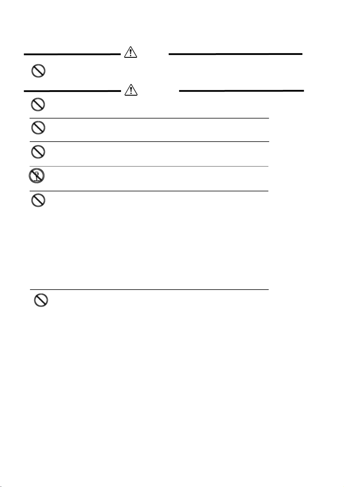
■
About the Scanner
Do not use this device near flammable substances (such as gas and explosives).
Prohibited
Do not throw this device into a fire. Doing so may cause the battery case to burst,
Prohibited
Prohibited
resulting in injury or possibly acting as an accelerant for the fire.
Do not insert foreign substances into the device. Doing so may short-circuit or overheat
the battery, resulting in fire or electric shock.
Do not use this device while walking or driving. Doing so may cause accidents.
Prohibited
Disassemble Prohibited
Prohibited
Do not disassemble or modify this device.
Do not use this device in the following areas. Doing so may cause fire, electric shock,
malfunction, or radio interference:
• In areas exposed to direct sunlight for long periods of time
• In dusty environments
• Near water or in extremely high humidity or other liquids
• Near heat sources, such as radiators, heat registers, stoves, or other types of apparatus
that produce heat
• Near microwaves, medical devices, or low-power radio stations. Read more in the
Medical equipment and Radio equipment sections.
Do not use this device while it is connected with the following equipments or environments.
Prohibited
This may affect the surrounding equipments by radio interference, resulting in injury or
physical damage.
DANGER
WARNING
-The medical equipments or safety devices designed to protect human body.
-The environment where the serious damage is concerned to occur.
4
Page 6

Do not drop this device or set it on an unstable surface from which it could fall.
Prohibited
Do not open the battery case lid in the area where battery is likely to contact with water.
Prohibited
Do not expose the battery pack to liquids or allow the battery contacts to get wet.
■
About the Rechargeable Battery
Do not attempt to modify or alter the battery. Doing so may cause the battery pack to
Prohibited
Prohibited
Prohibited
generate heat, or lead to burst, leakage, explosion or ignite.
Do not throw the battery into a fire. Doing so may cause the battery case to burst,
resulting in injury or possibly acting as an accelerant for the fire.
Do not short the power leads on the battery pack. If the (+) and (-) terminals
come in contact with metals (such as a necklace or hairpin), short-circuiting
occurs.
CAUTION
WARNING
Constraint
Constraint
Constraint
Constraint
Set the battery pack as indicated on the battery label.
If liquid from a leaking battery pack gets in the eyes, wash them with clean water and
consult a physician immediately.
Check the local regulations for proper battery disposal. This makes it possible to collect
and recycle used batteries and to save the environment.
CAUTION
When the device is not in use for a long period of time remove the battery pack. Over
time, batteries left in an unused device may leak, causing corrosion and resulting in
product malfunction.
5
Page 7

2. Handling Precautions
2.1 Please follow the following instructions for proper usage.
・ Do not leave this device in highly humid or dusty areas.
・ When condensation occurs, such as when moving this device from a cold to a warm environment, dry the
scanner before using it.
・ Do not leave this device in areas where static electricity is easily generated (such as the carpeted area) or near
equipment which generate magnetism (such as a TV or a radio).
・ This device is a precision apparatus. Do not subject this device to strong impact. Do not throw or drop this device
from large height.
・ When cleaning this device, rub gently with either a soft dry cloth or a damp cloth with mild detergent. Do not use
solvents; they may discolor the device.
・ Do not leave this device in direct sunlight or in a high temperature area.
・ Keep the battery pack away from water or all other liquid.
2.2 Radio Equipment
The OPI-4012, as radio equipment for low-power radio stations of 2.4 GHz band advanced data communication
systems specified in the Radio Law, has obtained the Certification for Construction Design of Specified Radio
Equipment. Therefore, it does not have radio station license in Japan.
The following activities are prohibited under the Radio Law:
• Remodeling and disassembly
• Peeling off the certificate label
2.3 Bluetooth
・ Bluetooth® is a trademark owned by its proprietor and used by OPTOELECTRONICS Co., Ltd. under license.
・ To communicate via Bluetooth, the device which the OPI-4012 is connected to must support the same Bluetooth
version and profile.
・ The OPI-4012 is compliant to Bluetooth standards. However, we do not guarantee the connection between the
OPI-4012 and other Bluetooth devices which have not been tested by us.
・ Bluetooth supporting devices use 2.4 GHz frequency band. However, many other sorts of devices also utilize this
frequency band. It may affect the communication speed or communication range of this device.
・ Communication speed and communication range of the OPI-4012 may differ due to the obstacles and radio
wave conditions between the OPI-4012 and the other Bluetooth device, which the OPI-4012 is connected to.
Conditions of the device, which the OPI-4012 is connected to, may also affect the communication speed and
communication range of the OPI-4012.
・ There is a Bluetooth antenna embedded to the OPI-4012. An extreme contact with a metal object may affect the
performance of the antenna.
6
Page 8

2.4 Frequency Band
This device uses the 2.4 gHz frequency band. Read the following information carefully before using this device.
In the frequency band of this scanner, scientific, medical and industrial devices, including microwaves, are
used. Also, other radio stations, including local private radio stations for mobile object i dentification and
stations requiring a license for manufacturing lines at factories, specific power-saving radio stations
requiring no licen se, and amatuer radio sta tions, are managed.
・ Please make sure that “other radio stations” are not managed in the frequency band 2.4 gHz before using this
device.
・ If radio interference occurs between this device and other radio stations, change the service space immediately,
or stop transmitting radiowaves to avoid the interference.
・ If you have any questions or troubles, please contact our marketing group.
9 OPTOELECTRONICS Co., Ltd. shall not be held responsible for any accidental data losses or data
damages which may occur by defects or accidents.
7
Page 9

3. Package Contents
The package contents are listed as below.
Please confirm that you have the following items before getting started.
- 1 scanner (OPI-4012) with an embedded battery pack
- 1 hand strap
- 1 copy of Instruction manual
- 1 dedicated AC adapter
9 The number of accessories may differ depending on the product specification.
9 Please contact the nearest dealer if accessories are damaged or missing.
8
Page 10
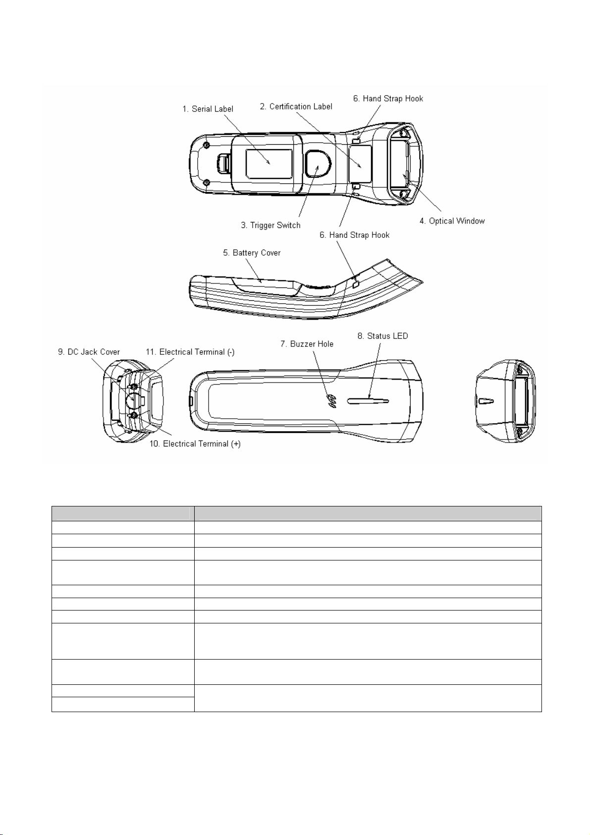
4. Detailed View
4.1 OPI-4012 (Scanner)
Part Function
1. Serial Label
2. Certification Label A certification label for wireless communication technology
3. Trigger Switch To scan and decode a barcode, you need to press the trigger switch.
4. Optical Window
The scanner emits a laser beam through the optical window while scanning a
barcode.
5. Battery Cover
6. Hand Strap Hook Those hooks are necessary to attach a hand strap.
7. Buzzer Hole Buzzer sounds through the buzzer hole.
The status LED is used to alert users to the status of the scanning
8. Status LED
operation, wireless connectivity, data storage, remaining battery level
and recharging time.
9. DC Jack Cover
10. Electrical Terminal (+)
11. Electrical Terminal (-)
A cover to protect DC jack. Open the cover when charging the scanner
using a dedicated AC adapter.
Charging terminals are used to supply power to the scanner from a dedicated cradle
(CHG-4001).
9
Page 11
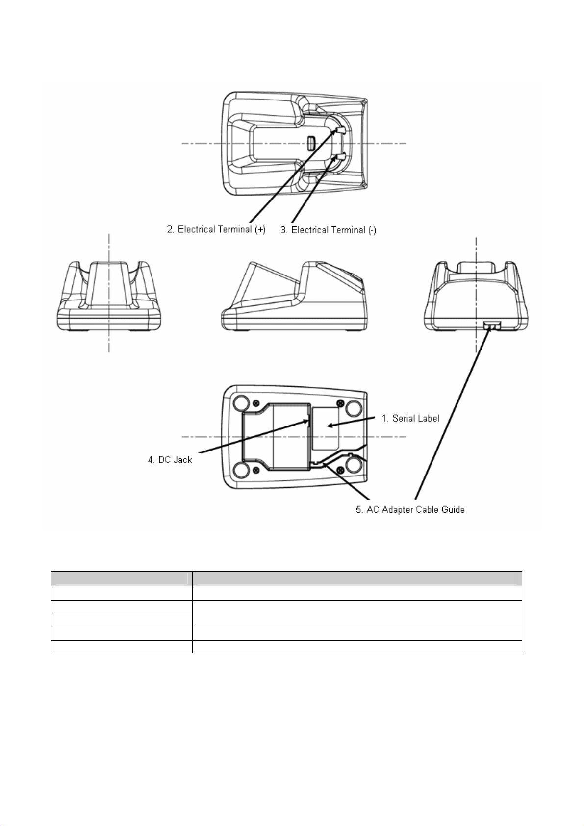
4.2 CHG-4001 (Dedicated cradle for the OPI-4012, optionally sold)
Name Functions
1. Serial Label
2. Electrical Terminal (+)
3. Electrical Terminal (―)
Charging terminals are used to supply power to the scanner from a dedicated
cradle (CHG-4001).
4. DC Jack Connect a dedicated AC adapter.
5. AC Adapter Cable Guide Install a dedicated AC adapter cable along the guide.
10
Page 12
5.Getting Started
About the OPI-4012
The OPI-4012 scanner is set to low power mode by default. Please press and hold down the trigger switch for a
while to activate the scanner. The scanner will not operate if the main battery is empty. Please charge the main
battery using a dedicated AC adapter before getting started. It is also possible to charge the main battery using a
dedicated cradle (CHG-4001).
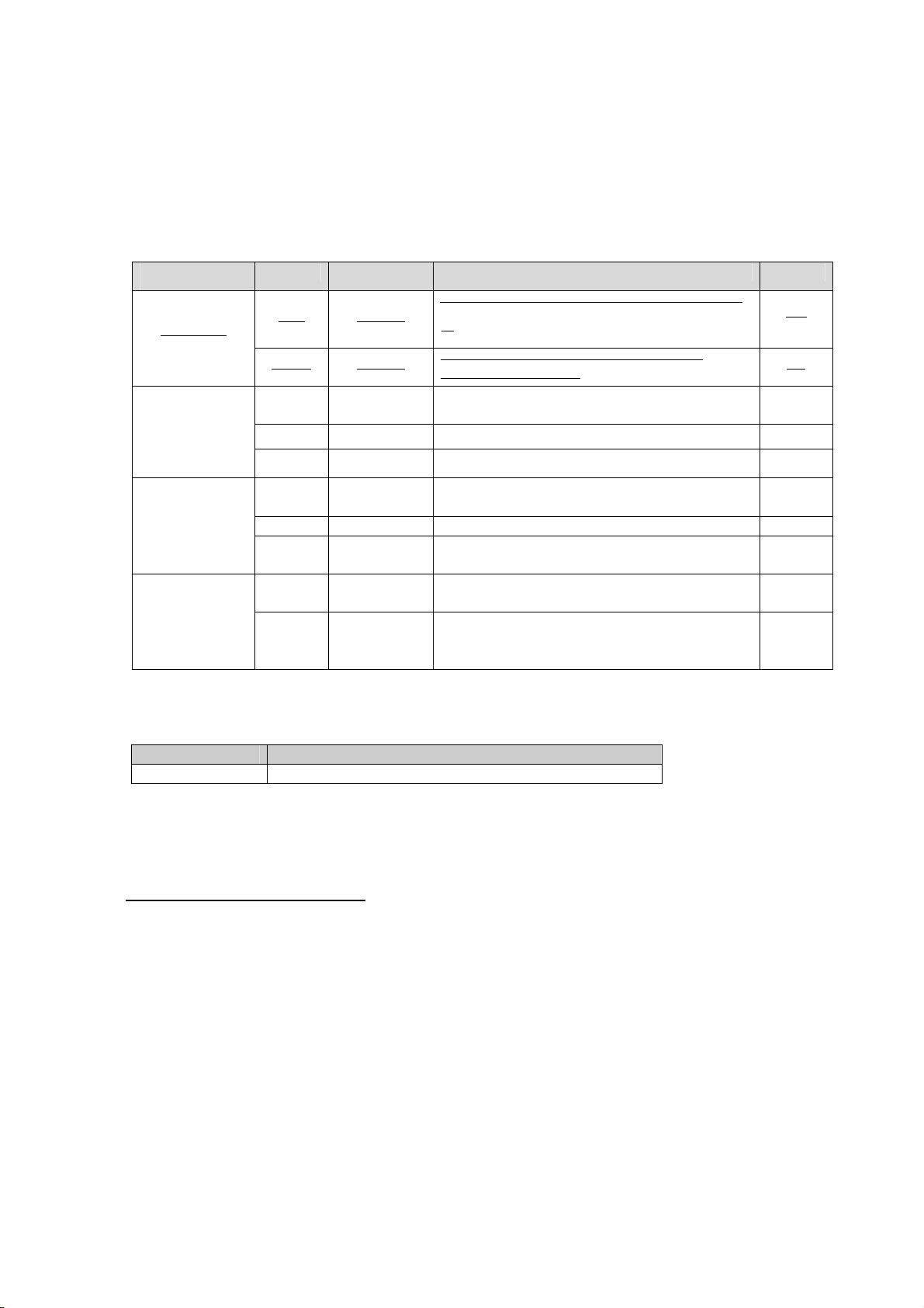
・ LED and Buzzer Notification
Status
Color
Display
Operating Status Buzzer
Charging
Scanning
Bluetooth
Connection
Bluetooth
Disconnection
Shows
Red Lighting
Lighting
Green
Green Blinking
Red Blinking Shows that the data could not be transmitted. Yes
Orange Blinking Shows that the data is being stored in memory. Yes
Green
Green Lighting Shows that a Bluetooth connection is made.. Yes
Red Lighting
Red Lighting
Red Lighting
Continuously
Blinking
*1
The light changes from red to green when
charging is completed.
Shows that the scan or data transmission was
executed normally.
Shows that a Bluetooth connection is being made.
Shows that the scanner failed to make a Bluetooth
connection.
Shows that the scanner has disconnected a
Bluetooth communication.
Shows that a Bluetooth communication is
disconnected for the scanner being in outside of
the communication range.
that the scanner is being charged.
* The LED does not turn red when the cradle detects a fully charged battery.
・ Charging Time
Specification Condition
About 3 hours To fully charge an empty battery.
About Hand Strap
No
No
Yes
No
Yes
Yes
Yes
Use the hand strap to avoid dropping the scanner when carrying or using it.
9 Do not swing the scanner around.
11
Page 13
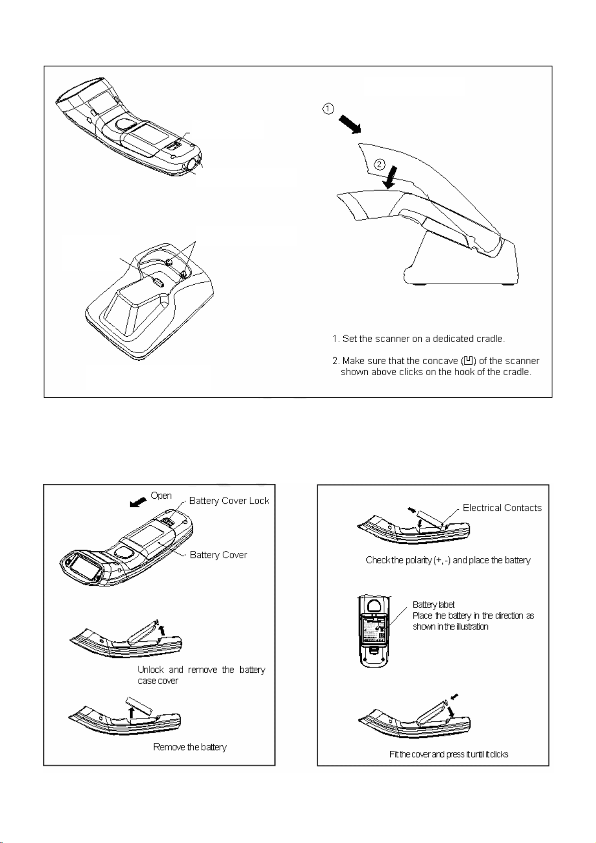
Charging the scanner (its main battery) on the CHG-4001 cradle
Concave (凹)
Scanner on the cradle
Switch for
terminal
detection
Electrical contacts
Replacing battery
<Removing battery> <Placing
battery>
12
Page 14
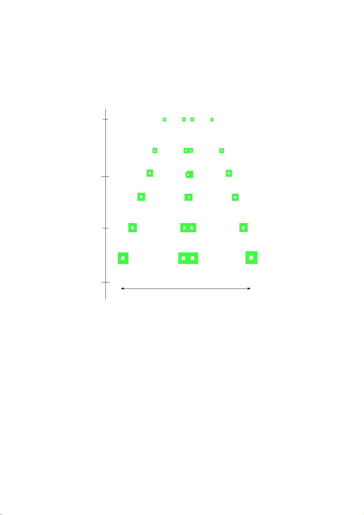
6.Scanning Barcodes
During a scan, the green LED patterns shown below will be visible. These patterns assist you in aiming the scanner;
they are superimposed on the illuminated scan field. The aiming patterns are only a guide. They do not indicate exact
scannable width or distance between a scanner and a barcode.
Distance from a Mask of a Camera
[in the millimeters]
30
80
130
180
How to use the aiming guide
• The focal point is where two central LED light patterns (green and square-shaped) overlap—where two dots
meet.
• To scan a barcode within the aiming range, make sure that two central LED light patterns overlap, then place
Horizontal Direction
the center of the overlapping LED light patterns on the center of the barcode.
• To scan a barcode wider than a width of the aiming range, aim at the barcode from further away. Make sure
that the barcode is between two LED light patterns on both the right and left.
9 Scanning performance may decline due to the specular reflection when the symbology is printed on certain
types of materials. I n such cases, incline the scanner at 15 degrees to adjust the scanning a ngle.
13
Page 15

7.Wireless Communication
7.1 Wireless Specifications
・ The OPI-4012 communicates using Bluetooth (Ver 2.0) wireless communication technology. The OPI-4012 supports
SPP (serial port profile) and communicates with other Bluetooth devices which support the same profile.
■ Protocol Stack
RF (Radio Frequency Protocol)
BB (Base Band Protocol)
LM (Link Manager Protocol)
L2CAP (Local Link Control and Adaptation Protocol)
RFCOMM (RS-232C Emulation)
■ Profile
GAP (Generic Access Profile)
SPP (Serial Port Profile)
■ Transmission Power
Class 2
■ Communication Configuration
1 Scanner (OPI-4012) to 1 Host
9 It is not possible to connect more than one scanner to one host.
■ Communication Mode
Scanner (OPI-4012): Master
Bluetooth device: Slave
■ Low Power Mode
Sniff mode is not supported.
■ Data Security
Encryption and authentication features are supported by the OPI-4012.
■ Communication Distance
Approximately 10 meters.
9 The communication distance may differ depending on the operating environments.
14
Page 16

7.2 Menu Barcode for the Configuration
・ Use menu barcodes to configure the following settings of the scanner:
9 Please carry out the configuration before making a Bluetooth connection.
9 Please refer to the Universal Menu Book for details.
■ Bluetooth Device Address Settings (Mandatory)
■ Bluetooth Security Settings
■ PIN Code Settings
■ Encryption Settings
■ Handshaking Settings
■ ACK/NAK Timeout Settings
■ Bluetooth Device Address Settings
・Carry out Bluetooth device address settings to identify the Bluetooth device to which the OPI-4012
will be connected.
・Refer to the Bluetooth device address label attached to the Bluetooth device. Find appropriate menu
barcodes to scan the 12-digit address.
9 You cannot connect more than one Bluetooth devices to one OPI-4012 scanner.
9 If you scan a wrong menu barcode, please start the setting from the beginning.
■ Bluetooth Security Settings
・Carry out this setting to provide safe connection between the scanner and the Bluetooth device..
・You must carry out authentication within 30 seconds. Please input the PIN code within the 30
seconds.
9 When the authentication is enabled, please set the PIN code before making connection.
9 When the authentication is disabled, the PIN code settings are not required.
■ PIN Code Settings
・When the authentication is enabled, PIN code settings are required.
・You also have to set the PIN code on the other Bluetooth device.
・The PIN code is a code of 1 to 16 characters.
■ Encryption Settings
・You can encrypt the scanned data by enabling the encryption setting..
9 When the other Bluetooth device does not support the encryption settings, the encryption
settings of the scanner will be invalid.
15
Page 17

■ Handshaking Settings
・You can set the handshaking for the communication between the host and the scanner.
・When it is set to “No handshaking”, the reliability of the transmitted data will be lower. It is
recommended to enable ACK/NAK.
9 ACK/NAK No Response
9 ACK/NAK
■ ACK/NAK Timeout Settings
・You can set the timeout for the ACK/NAK sent from the host.
■ Communication Settings
・Communication settings are set to the following by default:
Bluetooth Device Address Settings: Disabled
PIN Code Settings: Disabled
Encryption Settings: Disabled
Handshaking Settings: No Handshake
ACK/NAK Timeout Settings: 100 ms
The following communication settings can be configured using the attached menu barcode lists.
・
Auto connect
Data memorizing
Trigger connection
Press trigger switch time to connect
Press trigger switch time to disconnect
Auto disconnect
Auto reconnect
■ Auto Connect
・You can set the scanner to automatically connect after setting the Bluetooth device address.
■ Data memorizing
・Scanned barcode data will be stored in a memory automatically when the data memorizing setting is
enabled.
・The capacity of the memory is about 100KB.
・When the memory get full while the scanner is outside of the communication range, the scanner
sounds a buzzer and you will not be able to continue the scanning operation.
・The stored data will be transmitted automatically when the scanner returns to the communication
range.
・If you scan the data clear menu barcode [+-MCLR-+] or the IEEE address label while resending the
stored data outside of the communication range, the stored data will be deleted.
・If you disable the data memorizing settings while the scanner is outside of the communication range,
the stored data will be deleted.
16
Page 18

9 The scanner will not carry out the scanning operation if the data memorizing setting is
disabled.
9 Auto reconnect feature will operate in every 20 seconds.
■ Trigger Connection
・You can set the scanner to connect or disconnect by pressing down the trigger key for the set
duration.
■ Press trigger switch time to connect
・This is the time the trigger switch needs to be pressed where after the scanner tries to establish a
connection.
■ Press trigger switch time to disconnect
・This is the time the trigger switch needs to be pressed where after the scanner disconnects.
■ Auto disconnect
・If the scanner is idle for configured time, it will be disconnected.
■ Auto reconnect
・If the scanner is disconnected because it is out side of the communication range, the reader will try
to establish connection during the configured time.
■ Default setting [S0]
・Foregoing settings are set to the following by default:
Auto Connect: Enabled
Data Memorizing: Enabled
Trigger Connection: Disabled
Press trigger switch time to connect: 3 seconds
Press trigger switch time to disconnect: 5 seconds
Auto disconnect: Disabled
Auto reconnect: 5 minutes
17
Page 19

8.How to Configure the Wireless Communication Settings
8.1 Connect without Authentication
1. Use the universal menu book to set the scanning options and read options of the scanner.
・ This operation will not be necessary if you would like to use the scanner with the default settings.
2. Use this instruction manual to set the communication settings.
・ Scan the menu barcode “Connect to PC”. (The trigger connect option will be enabled.)
・ Scan the numbers and characters of the 12-digit Bluetooth device address.
3. Establish connection with the Bluetooth device as follows:
・ Scan a 12-digit Bluetooth device address
・ Press trigger key for the set duration.
・ Scan “Manually connect” menu barcode [+-CONN-+].
4. The LED of the scanner blinks green light and make connection.
5. Once the scanner makes connection successfully, the LED turns solid green and the scanner sounds a buzzer.
・ If the scanner fails in making connection, the LED of the scanner blinks red light and the scanner sounds a
warning buzzer. *
6. You will be able to scan barcodes.
7. You can disconnect the Bluetooth communication as follows:
・ Scan “Manually disconnect” menu barcode [+-DISC-+].
・ Press trigger key for the set duration.
8. The LED of the scanner turns solid red and the scanner sounds a warning buzzer when it disconnect Bluetooth
connection.
Notes:
* Please make sure that the authentication is disabled.
* Please confirm the Bluetooth device address.
18
Page 20

8.2 Connect with Authentication
1. Use the universal menu book to set the scanning options and read options of the scanner.
・ This operation will not be necessary if you would like to use the scanner with the default settings.
2. Use this instruction manual to set the communication settings.
・ Scan the menu barcode “Connect to PC”. (The trigger connect option will be enabled.)
・ Scan the numbers and characters of the 12-digit Bluetooth device address using the attached list of menu
barcodes.
・ Scan the menu barcode “Enable authentication”.
・ Scan the numbers of the PIN code using the attached list of menu barcodes.
・ If you desire to encrypt the scanned data, scan the menu barcode “Enable encryption”.
3. Establish connection with the Bluetooth device as follows:
・ Scan a 12-digit Bluetooth device address
・ Press trigger key for the set duration.
・ Scan “Manually connect” menu barcode [+-CONN-+].
4. The LED of the scanner blinks green light and make connection.
5. Input the same PIN code to the Bluetooth device.
6. Once the scanner makes connection successfully, the LED turns solid green and the scanner sounds a buzzer.
・ If the scanner fails in making connection, the LED of the scanner blinks red light and the scanner sounds a
warning buzzer. *
7. You will be able to scan barcodes.
8. You can disconnect the Bluetooth communication as follows:
・ Scan “Manually disconnect” menu barcode [+-DISC-+].
・ Press trigger key for the set duration.
9. The LED of the scanner turns solid red and the scanner sounds a warning buzzer when it disconnect Bluetooth
connection.
Notes:
* Please make sure that the authentication is disabled.
* Please confirm the Bluetooth device address.
* Please confirm the PIN code.
19
Page 21

■Notes
・ The scanner does not scan any barcodes other than menu barcodes before it is connected to the Bluetooth device.
(If the [BM1] settings are configured, the scanner will scan other barcodes.)
・ If you scan a 12-digit barcode label before connecting the scanner to the Bluetooth device, the scanner will
acknowledge the 12-digit barcode as a Bluetooth device address.
- Before establishing Bluetooth connection:
• A 12-digit barcode label with quiet zones on both ends (Code 39) Æ Acknowledged as a Bluetooth address
• A 12-digit barcode label Æ Acknowledged as a Bluetooth address
- After establishing Bluetooth connection:
• A 12-digit barcode label with quiet zones on both ends (Code 39) Æ Acknowledged as a Bluetooth address
• A 12-digit barcode label Æ Acknowledged as a barcode
・ If the battery voltage gets low, the LED lights red when scanning a barcode. Please charge the scanner.
・ When the scanner is outside of the communication range or when the Bluetooth communication is disconnected, the
LED of the scanner turns solid red and the scanner sounds a buzzer.
・ When the scanner carries out a scanning operation outside of the communication range, the LED of the scanner
turns orange and the buzzer sound changes.
・ When the scanner is set to “data memorizing disabled”, the scanner will not carry out scanning operation outside of
the communication range.
・ When the memory of the scanner gets full while the scanner is outside of the communication range, you will not be
able to continue the scanning operation.
・ The scanner tries to automatically reconnect in every 20 seconds while it is outside of the communication range.
・ When the “trigger connection option” is enabled, the scanner will stop the auto reconnect operation and establish the
connection when the trigger is pressed for the set duration (press trigger switch time to connect).
・ In this case, the stored barcode data will be deleted.
・ Also, if you disable the data memorizing settings while the scanner is outside of the communication range, the stored
data will be deleted.
・ If you use a trigger key to reconnect while the scanner is set to [CA00], the scanner will return to the idle mode and
stored data will be deleted. To reconnect using the trigger key, do not set to [CA00] but set to [CA99] and [BM1].
20
Page 22

9.Default Settings
* Refer to the Product Specification Manual and the Universal Menu Book for the readable codes.
9.1 Default Settings 1: Readable Codes
Code type Reading
UPC-A
UPC-A Add-on
UPC-E
UPC-E1
UPC-E Add-on
EAN-13
EAN-13 Add-on
EAN-8
EAN-8 Add-on
CODE-39
Tri-Optic
NW-7(CODABAR)
Industrial 2of5
Interleaved 2of5
Matrix 2of5
Chinese Post matrix 2of5
Korean Postal Authority code
S-CODE
Telepen
CODE-93
CODE-128
MSI/Plessey
UK/Plessey
IATA
PDF417
Micro PDF417
QR CODE
Micro QR
Data Matrix (ECC200)
Data Matrix (ECC0-140)
Maxi CODE
Aztec CODE
Transmit
code
length
○ × ○ ○
× × ○ ○
○ × ○ ○
× × ○ ○
× × ○ ○
○ × ○ ○
× × ○ ○
○ × ○ ○
× × ○ ○
○ × ○ ×
○ × ○ ×
○ × ○ ×
○ × ○ ×
○ × ○ ×
× × ○ ×
× × ○ ×
× × × ○
○ × ○ ×
○ × × ○
○ × ○ ○
○ × ○ ○
○ × ○ ○
○ × ○ ○
○ × ○ ○
○ × × ○
○ × × ○
○ × × ○
× × × ○
○ × × ○
× × × ○
○ × × ○
○ × × ○
Transmit
CD
Calculate
CD
Transmit
other
Not transmit
ST/SP
Not transmit
ST/SP
Not transmit
ST/SP
Aztec Runes × × × ○
Prefix
settings
-
-
-
-
-
-
-
-
-
-
-
-
-
-
-
-
-
-
-
-
-
-
-
-
-
-
-
-
Suffix
setting
s
CR
CR
CR
CR
CR
CR
CR
CR
CR
CR
CR
CR
CR
CR
CR
CR
CR
CR
CR
CR
CR
CR
CR
CR
CR
CR
CR
CR
21
Page 23
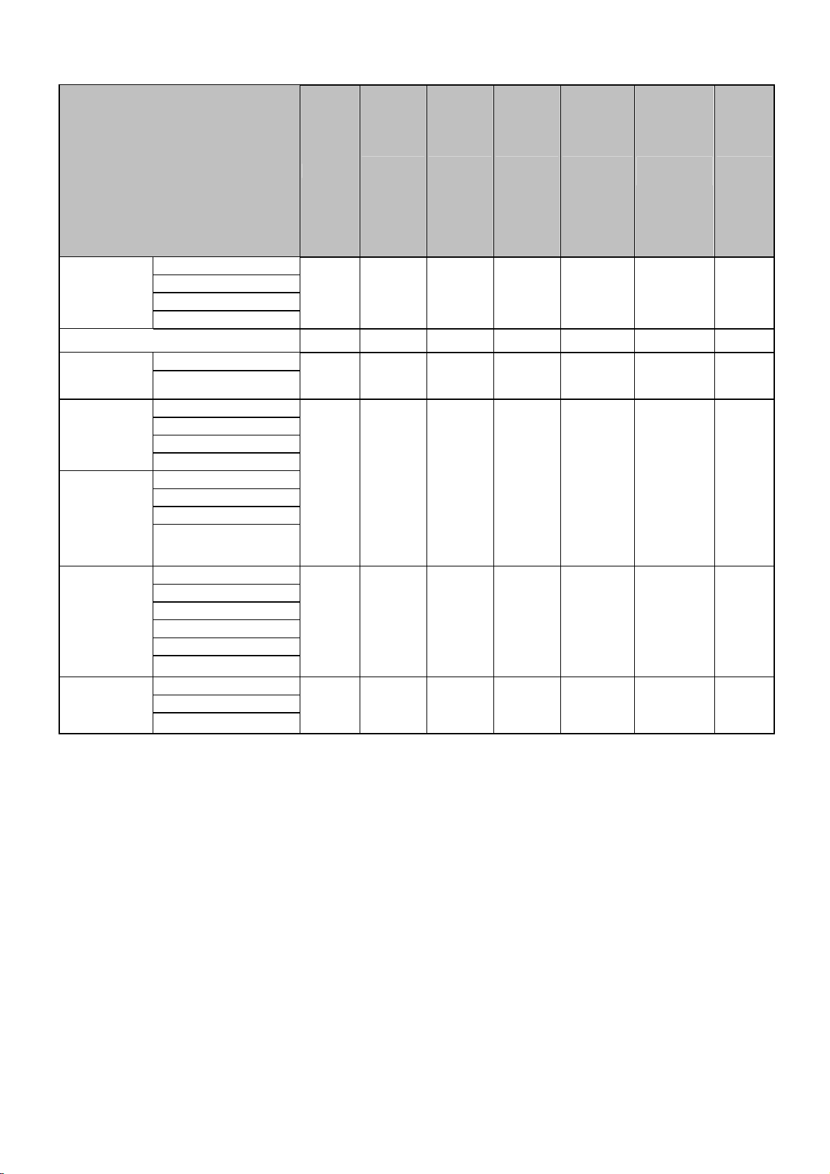
9.1 Default Settings 1: Readable Codes (continued)
RSS-14
RSS Limited
Expanded
Composite
EAN
Composite
UPC
Code type Reading
Standard
Truncated
Stacked
○ × × ○
Stacked Omni-directional
○ × × ○
Standard RSS
Stacked
○ × × ○
EAN-13 CCA
EAN-13 CCB
EAN-8 CCA
EAN-8 CCB
UPC-A CCA
× × × ○
UPC-A CCB
UPC-E CCA
UPC-E CCB
Transmit
code length
Transmit
CD
Calculate
CD
Transmit
other
Prefix
settings
- CR
-
- CR
- CR
Suffix
settings
Composite
RSS
RSS-14 CCA
RSS-14 CCB
RSS Limited CCA
RSS Limited CCB
× × × ○
- CR
RSS Expanded CCA
RSS Expanded CCB
Composite
UCC/EAN-128
UCC/EAN-128 CCA
UCC/EAN-128 CCB
× × × ○
- CR
UCC/EAN-128 CCC
Note:
1) In the column of “Reading”, “○” means “Enable to read” and “×” means “Disable to read”.
2) In the column of “Transmit code length”, “○” means “Transmit code length” and “×” means “Not transmit code length”.
3) In the column of “Transmit CD”, “○” means “Transmit check digit”, “×” means “Not transmit check digit ”.
4) In the column of “Calculate CD”, “○” means “Calculate check digit” and “×” means “Not calculate check digit”.
5) In the column of “Prefix settings”, “-” means “There is no Prefix settings”.
22
Page 24
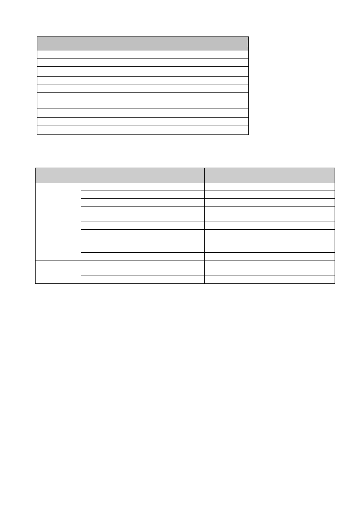
9.2 Default Settings 2: Read Options, Trigger, Buzzer, LED settings
Parameter Default Settings
Setting the number of characters Fixed length OFF all codes
Read mode Multiple read
Inter-character gap check (NM-7) Character *1 > Inter-character gap
Multiple columns read (barcode only) Disabled
Trigger switch Enabled
Read time 2 seconds
Buzzer durations 200 msec
Buzzer tone
3kHz+2.5kHz
Buzzer loudness Loud
LED indicator duration 200 msec
9.3 Default Settings 3: Communication settings
Parameter Default Settings
Device address Bluetooth device
Data memorizing Disabled
Trigger connection Disabled
Wireless
Communication
Settings
Press trigger switch time to connect Disabled
Press trigger switch time to disconnect Disabled
Auto disconnect Disabled
Auto reconnect 5 minutes
ACK/NAK No Handshake
ACK/NAK Timeout 1 second
PIN Code Enabled (last 4 digits of the BD address)
Bluetooth
Connection
Setting
Auto connect Enabled
Authentication Enabled (authentication if not paired)
Encryption Disabled
10.Menu Barcodes
This section contains the menu barcodes of the OPI-4012 default settings.
Other menu labels are listed in the Universal Menu Book, such as Code options, String options, Read options, and Indicator
options.
10.1 Setting Method
There are two ways to configure the settings:
Setting 1. Scanning CODE39 barcodes:
To set the required options, proceed as follows: Scan the Set label, the required label, and the END label in sequence.
* If several labels in the same option are read, the last label read is enabled.
Setting 2. Scanning QR code:
This needs to scan directly without reading the “SET” and “END” labels.
23
Page 25

<Menu Barcodes>
24
Page 26
<Bluetooth Options >
CODE39 labels QR code label
SET ZZ
Connect to
END ZZ
SET ZZ
Bluetooth address
setting
CNPC Connect to PC
CNCR Connect to Cradle
CODE39 labels QR code label
BDAS
BDAE
Set Bluetooth
address
End Bluetooth
address
_Z7_
_CNPC_
_CNCR_
_ZZ_
_ZZ_
_BDAS_
_BDAE_
END ZZ
_ZZ_
25
Page 27

Barcode for Bluetooth address setting
0
1
2
3
4
_Q0_
_Q1_
_Q2_
_Q3_
_Q4_
9
A
B
C
_Q9_
_0A_
_0B_
_0C_
5
6
7
8
Flow : [ZZ]⇒[BDAS]⇒[12Digit Bluetooth address]⇒[BDAE]⇒[ZZ]
_Q5_
_Q6_
_Q7_
_Q8_
D
E
F
_0D_
_0E_
_0F_
In case reading wrong address, restart from reading [BDAS]
26
Page 28
CODE39 labels QR code label
SET ZZ
Authentication
END ZZ
SET ZZ
Encryption
AUTE Enable
AUTD Disable
CODE39 labels QR code label
ENCE Enable
ENCD
Disable
_ZZ_
_AUTE_
_AUTD_
_ZZ_
_ZZ_
_ENCE_
_ENCD_
END ZZ
_ZZ_
27
Page 29

CODE39 labels QR code label
SET ZZ
PIN code
PINS Set PIN code setting
0
1
2
3
4
5
6
_ZZ_
_PINS_
_Q0_
_Q1_
_Q2_
_Q3_
_Q4_
_Q5_
_Q6_
7
8
9
PINE End PIN code setting
END ZZ
_Q7_
_Q8_
_Q9_
_PINE_
_ZZ_
28
Page 30
<Communication and Connection>
CODE39 labels QR code label
SET ZZ
ENAU Enable
Auto connect
DIAU Disable
END ZZ
<Connection/Disconnection>
Manually connect +-CONN-+
Manually disconnect +-DISC-+
_ZZ_
_enau_
_diau_
_ZZ_
_+-CONN-+_
_+-DISC-+_
<Default (Interface)>
SET ZZ
Default SO
END ZZ
]
]
OPTOELECTRONICS Co., Ltd.
CODE39 labels QR code label
_ZZ_
_SO_
_ZZ_
OPI-4012 Instruction Manual
Marketing Group
12-17, Tsukagoshi 4-chome, Warabi, Saitama 335-0002 Japan
TEL: +81-48-446-1183 FAX:
+81-48-434-2820
29
Page 31

FCC Statement
This equipment has been tested and found to comply with the limits for a Class B
digital device, pursuant to part 15 of the FCC rules. These limits are designed to
provide reasonable protection against harmful interference in a residential installation.
This equipment generates, uses and can radiate radio frequency energy and, if not
installed and used in accordance with the instructions, may cause harmful interference
to radio communications. However, there is no guarantee that interference will not
occur in a particular installation. If this equipment does cause harmful interference
to radio or television reception, which can be determined by turning the equipment off
and on, the user is encouraged to try to correct the interference by one or more of the
following measures:
-Reorient or relocate the receiving antenna.
-Increase the separation between the equipment and receiver.
-Connect the equipment into an outlet on a circuit different from that to which the
receiver is connected.
-Consult the dealer or an experienced radio/TV technician for help.
FCC Radiation Exposure Statement
This device complies with Part 15 of FCC RF Rules. Operation is subject to the
following two conditions:
1) this device may not cause interference and
2) this device must accept any interference, including interference that may cause
undesired operation of the device.
This equipment complies with FCC RF radiation exposure limits set forth for an
uncontrolled environment
 Loading...