

Page 1

Master Specifications
Wireless Laser Barcode Scanner
Product Name OPR-3101
Publication No. SS07028
Edition Initial Release
Date of Publication April 3, 2007
Original Doc. No. SS07012
OPTOELECTRONICS Co., Ltd.
5-3 Tsukagoshi, 5-chome,
Warabi-shi, Saitama,
335-0002 Japan
TEL: 81+(0)48-446-1183
FAX: 81+(0)48-434-2820
Page 2

OPR-3101 SS07028
Revision History
Specification No.: SS07028
Product name : OPR-3101
Revision Date Section Description of Changes
Initial
Release
2007/04/03
Page 3

OPR-3101 SS07028
Table of Contents
1. ABSTRACT ......................................................................................................................................... 1
2. OVERVIEW ......................................................................................................................................... 1
3. BASIC SPECIFICATIONS ................................................................................................................... 2
4. DETAILED VIEW................................................................................................................................. 4
5. ELECTRICAL SPECIFICATIONS........................................................................................................ 6
6. OPTICAL SPECIFICATIONS............................................................................................................... 7
7. TECHNICAL SPECIFICATIONS.......................................................................................................... 8
8. WIRELESS CONNECTION............................................................................................................... 12
9. DEFAULT SETTINGS........................................................................................................................ 13
10. SERIAL LABEL, SERIAL NO., REGULATIONS .............................................................................. 16
11. PACKAGING SPECIFICATIONS ..................................................................................................... 17
12. ENVIRONMENTAL SPECIFICATIONS ........................................................................................... 19
13. RELIABILITY ................................................................................................................................... 21
14. WARRANTY.................................................................................................................................... 21
15. REGULATORY COMPLIANCE........................................................................................................ 22
16. REDUCTION OF ENVIRONMENTAL LOADS................................................................................. 22
17. PRECAUTIONS .............................................................................................................................. 23
18. AUTO TRIGGER ............................................................................................................................. 25
APPENDIX: MECHANICAL DRAWINGS .............................................................................................. 26
Page 4

OPR-3101 SS07028
1. Abstract
This manual provides specifications for the OPR-3101 gun-type wireless laser barcode scanner.
2. Overview
The OPR-3101 scanner utilizes Bluetooth technology to carry out wireless transmission of
scanned barcode data. Main features of the OPR-3101 are as follows:
・ Laser beam scanning
The use of short wave-length red laser beam enhances the visibility of scanning lines.
・ Customized ASIC for decoding
Utilization of high speed ASIC increases the data processing speed and improves the
OPR-3101 reading performance of low-quality printed barcode.
・ Rugged housing for heavy duties
The OPR-3101 is enclosed in a rugged housing sealed to IP-54 standards that withstands
repeated drops of up to two meters onto concrete. This scanner is suitable for the use not
only in office or shops but also in the warehouses.
・ Bluetooth technology for wireless communication
The OPR-3101 supports Bluetooth with output power Class 2. It enables the data
communication in the range as long as 10 meters.
・ Rechargable in the designated cradles.
It takes only about 5 hours to fully recharge the OPR-3101 in the designated cradle
CHG-3101 or CRD-3101. CHG-3101 recharges the scanner while CRD-3101 offers both
recharging and communication features. (It takes about 10 hours to recharge the battery
using USB bus power.)
・ Wide range of supported symbologies
EAN, JAN, UPC, Industrial 2of5, IATA, Interleaved 2of5, NW-7(Codabar), Code 39, Code
93, Code 128, MSI/Plessey, ISBN (13-digit JAN + 5-digit add on), RSS-14 Family, and
MicroPDF417 are supported.
*Please refer to Chapter 10 of this document for details of the default setting.
・ Complies with RoHS
OPR-3101 complies with RoHS.
1
Page 5
OPR-3101 SS07028
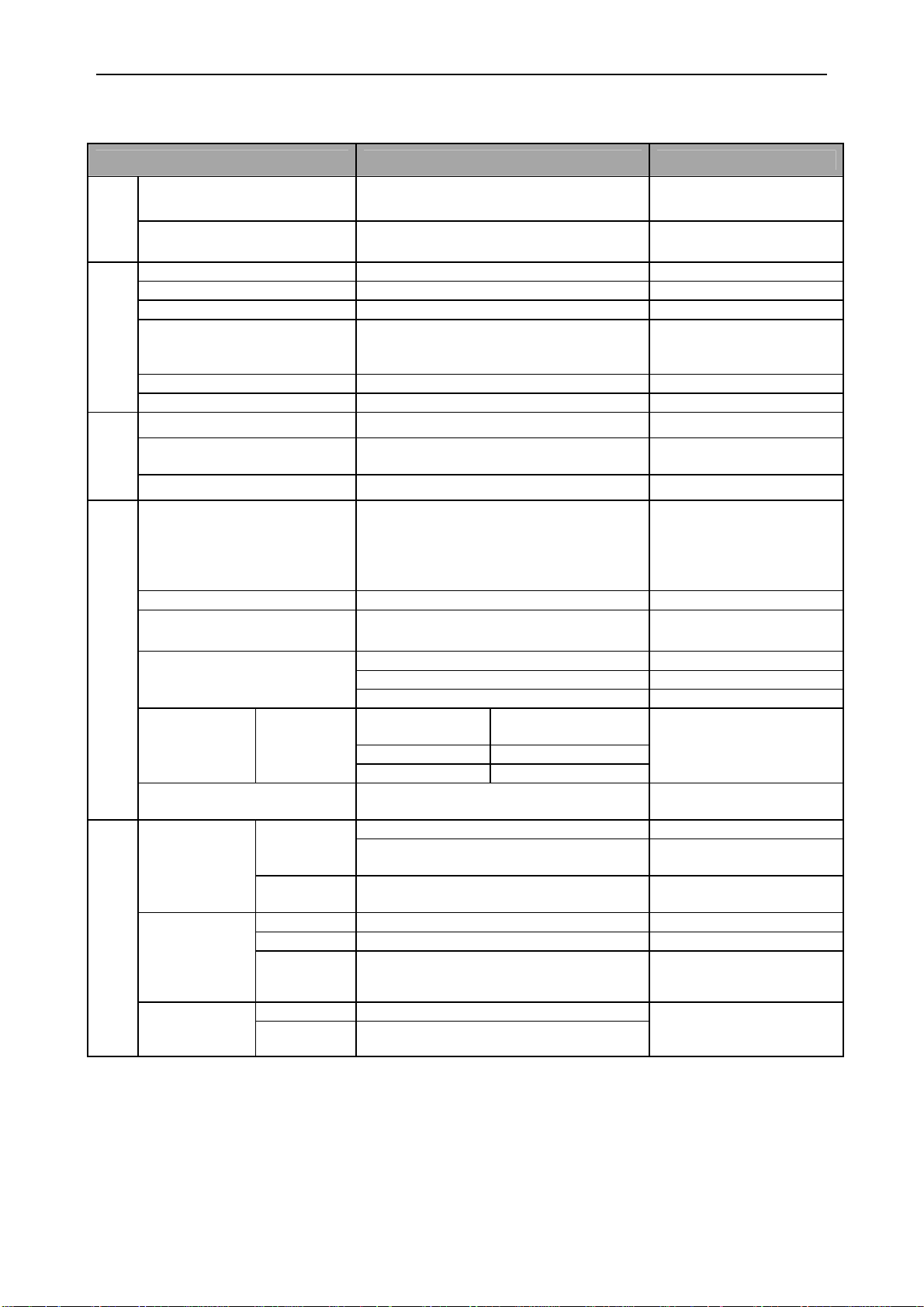
3. Basic Specifications
Items Specifications Notes
Section
Control
ASIC T6X53XBG
Flash ROM 4Mbits (256K × 16Bits) Flash Memory
CPU: ARM7TDMI,
Core: 48MHz
Communication
Wireless
Section
Optical
Specifications
Technical
Power Supply
Sections
Frequency 2,400 MHz to 2,483.5 MHz
Specifications Bluetooth Ver. 2.0 Protocol: SPP
Transmission Power Class 2 (4 dBm or less)
It may differ depending
Communication Range 10 m
Baud Rate 115.2 kbps
Antenna 1/4λ Surface-mounted Type Antenna
Scan Method Bi-directional 100 ±20 scan/sec
Light Emitting Element Red laser diode
Light Output ≤ 1.0 mW Laser Class 2 Product
EAN, JAN, UPC, Industrial 2of5, IATA,
Interleaved 2of5, NW-7(Codabar), Code
Supported Symbologies
Minimum Resolution 0.127 mm
Curvature
Scan Angle
DOF
(mm)
Minimum PCS 0.45 or higher
Main Battery
Current
Consumption
(at 3.7 V )
Battery Hour
Code 39
Spec.
Charge
Time
Peak 220 mA When scan and decode
Average 165 mA When scan and decode
Idle 30 mA (typ)
Idle About 48 hours
In Use
(1scan/5sec)
39, Code 93, Code 128, MSI/Plessey,
ISBN (13-digit JAN + 5-digit add on),
RSS-14Family, MicroPDF417 etc…
Radius ≥ 15 mm (with 8-digit JAN)
Radius ≥ 20 mm (with 13-digit JAN)
Pitch: α ≤ ± 35°
Skew: β ≤ ± 50° (Excluding dead zone.) PCS 0.9
Tilt: γ ≤ ±20°
Resolution:
0.127
Resolution: 0.25 20 to 230
Resolution: 1.0 40 to 720
Lithium-ion Secondary Battery
Nominal Capacity: 1620 mAh
Nominal Voltage: 3.7 V
About 5 hrs (using AC adaptor)
About 10 hrs (using USB bus)
About 25 hours
30 to 100
on the environmental
conditions.
Wavelength: 650±10nm
(at 25 deg. C)
Refer to Chapter 10 for
details.
Code 39 (PCS 0.9)
PCS 0.9
PCS 0.9
With over 70% reflectivity
of space and quiet zone.
When discharging 0.2
CA.
When idling
(communication
disconnected)
Battery hour with a fully
charged battery.
2
Page 6
OPR-3101 SS07028
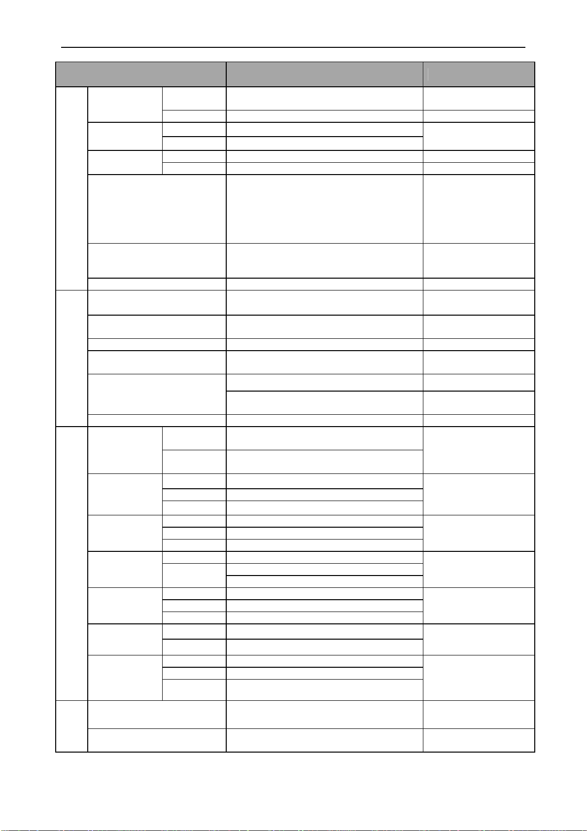
Items Specifications Notes
Environmental
Spec.
Regulations and Safety
Durability Tests
Physical
Spec.
Temperature
Operating -10 to 60 degrees C
Storage -20 to 60 degrees C
Humidity
Operating 5 to 95 % (no condensing)
Storage 5 to 95 % (no condensing)
Fluorescent up to 4,000 lx Ambient Light
Immunity
Sunlight up to 80,000 lx
Increased the frequency of vibration from
Vibration
10Hz to 100Hz at an accelerated velocity
of 19.6m/s
X-direction, Y-direction and Z-direction.
2
(2G) for 6 minutes each in
Repeated this test for 10 times in each
directions.
Dropped from a height of 200 cm onto a
Drop
concrete surface. The drop test was done
18 times.
Protective Structure IP54
Laser Safety
EMI
JIS C 6802:2005 Class 2
IEC 60825-1+A2:2001 Class 2
VCCI Class B, EN55022 Class 2, FCC
Part 15 Subpart C
Product Safety IEC/EN 60950-1
Electromagnetic
Compatibility (EMC)
EN61000-6-1 Class-B
CE Marking
Other Certifications
Certifications for Construction Design of
Specified Radio Equipment
Logo Certifications Bluetooth Logo Certification
Impressed static electricity of 15kV for 50
times on the surface of the scanner.)
Contact Discharge (direct/indirect): ± 6 kV
Air Discharge (direct):± 8 kV
80 to 1000 MHz
3 V/m
80 %
Alternating-current Input Cable: ± 1 kV
5 / 50 ns ( Tr / Tw)
5 kHz
1.2 / 50 ns ( Tr / Th)
From L to P: ± 2 kV (closed-loop voltage)
From L to L: ± 1 kV (closed-loop voltage)
0.15 to 80 MHz
3 V
80 %
50 and 60 Hz
3 A/m
Drop 30 %, 0.5 Cycles
Drop 60 %, 5 Cycles
Drop 95 %, 250 Cycles
Resistance to
Static Electricity
Amplitude
Modulation
(AM) caused by
Radio Signal
Fast Transient
Surge Voltage
Radio
Frequency
Common Mode
Power Supply
Frequency
Magnetic Field
Voltage Dip,
Momentary
Voltage Drop
etc…
No
destruction
No
malfunction
Frequency
Level
AM
Voltage
Pulse
Frequency
Pulse
Voltage
Frequency
Level
AM
Frequency
Level
Dip 1
Dip 2
Momentary
Drop
Dimensions 68(W) × 155(D) x 165(H) mm
When charging at
0 to 40degrees C
IEC:61000-4-2
compliant test
IEC61000-4-3
compliant test
IEC61000-4-4
compliant test
IEC61000-4-5
compliant test
IEC61000-4-6
compliant test
IEC61000-4-8
compliant test
IEC61000-4-11
compliant test
Weight 250 g
Excluding a 40-gram
battery pack.
3
Page 7
OPR-3101 SS07028
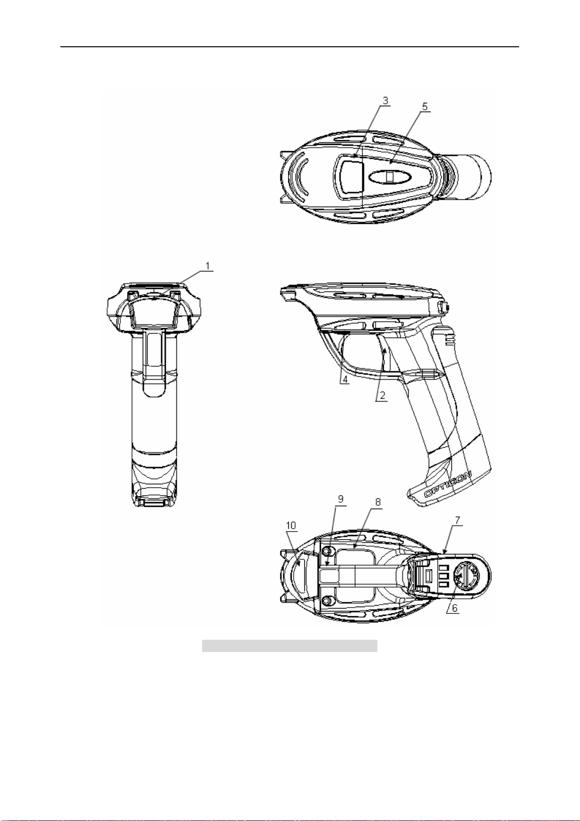
4. Detailed View
Figure 1: Detailed View of OPR-3101
4
Page 8

OPR-3101 SS07028
1. Plastic Mask
The scanner emits a laser beam through its plastic mask while scanning a bar code. Specular
light of the barcode comes in through the plastic mask. Keep the plastic mask clean.
2. Trigger Switch
To scan and decode a bar code, you need to press the trigger switch. After decoding, the data
is sent to the host via Bluetooth wireless communication.
3. Status LED
The scanner LED lights up Blue when the scanner registers a successful read. If the scan
fails, the LED lights up Red. LEDs are also used to alert users to the status of the wireless
connectivity, data storage (data collection), remaining battery level and recharging time.
4. Buzzer Holes
Buzzer sounds through these holes. Buzzer cannot be heard when those holes are
covered. Buzzer sounds upon the completion of scanning or data transmission. It also
sounds when connecting or disconnecting wireless communication.
Buzzer settings can be configured in various ways. You can enable or disable the buzzer
as well as change the buzzer loudness or duration.
5. Strap Hook
Strap hook is used to prevent the users from dropping the scanner. Do not swing the
scanner while connected to the strap hook or you may damage the scanner.
6. Battery Cover
To remove the battery cover, turn the battery cover lock counterclockwise with a coin and
remove the cover. When refastening the cover, turn the cover lock clockwise until it is
close-fitting. Always make sure the cover is locked correctly or the battery may fall out, or
may cause the scanner to perform poorly due to the water intrusion.
7. Battery Charging Terminals
Battery charging terminals are used to supply power to the scanner from the designated
cradle. Keep the terminals clean or it will degrade charging performance.
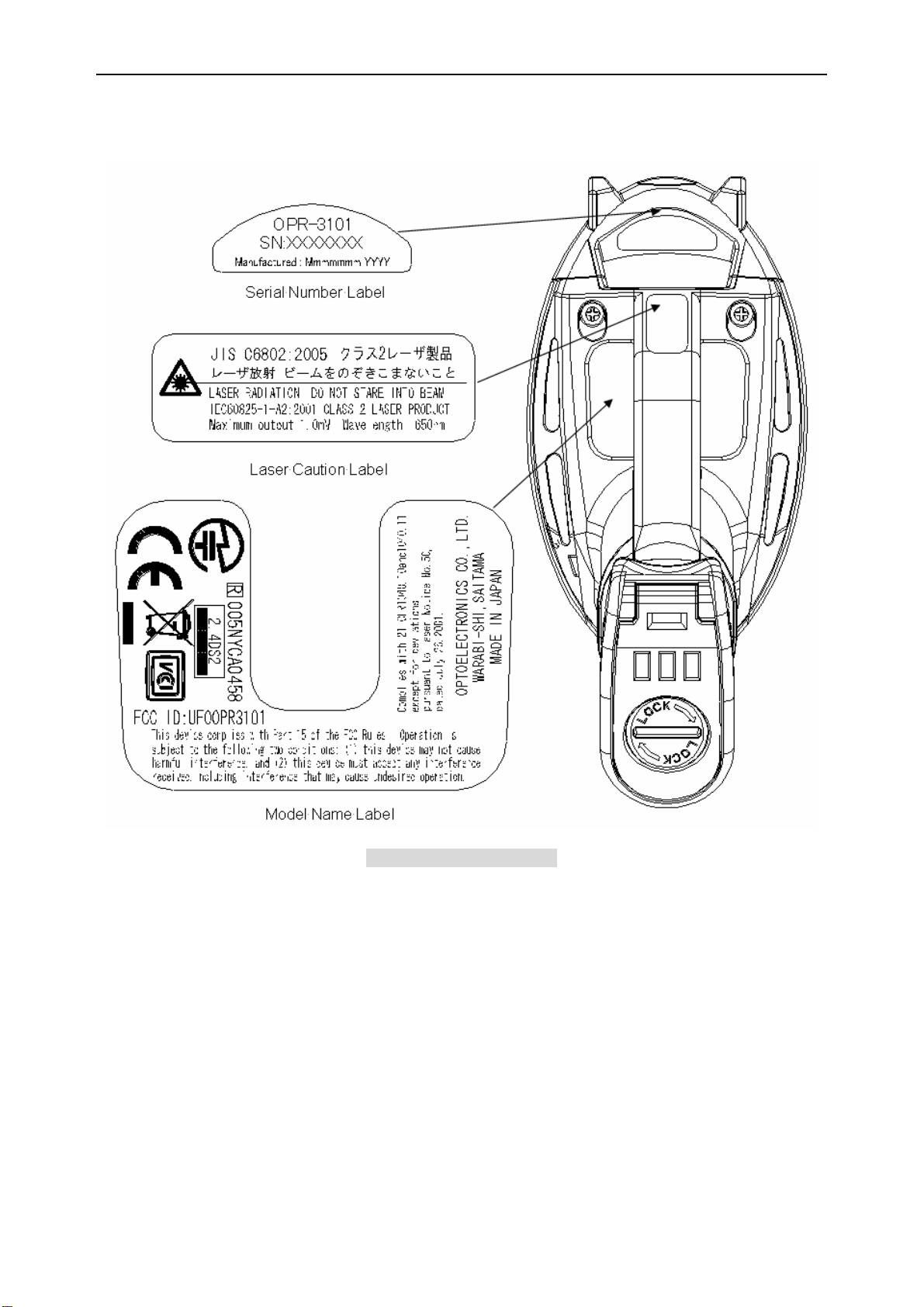
8. Model Name Label
This label shows certification logos, serial number and name of manufacturer of the unit.
9. Laser Caution Label
This label provides a caution mark and statememts for laser safety.
10. Serial Number Label
This label shows the model name and serial number.
5
Page 9
OPR-3101 SS07028
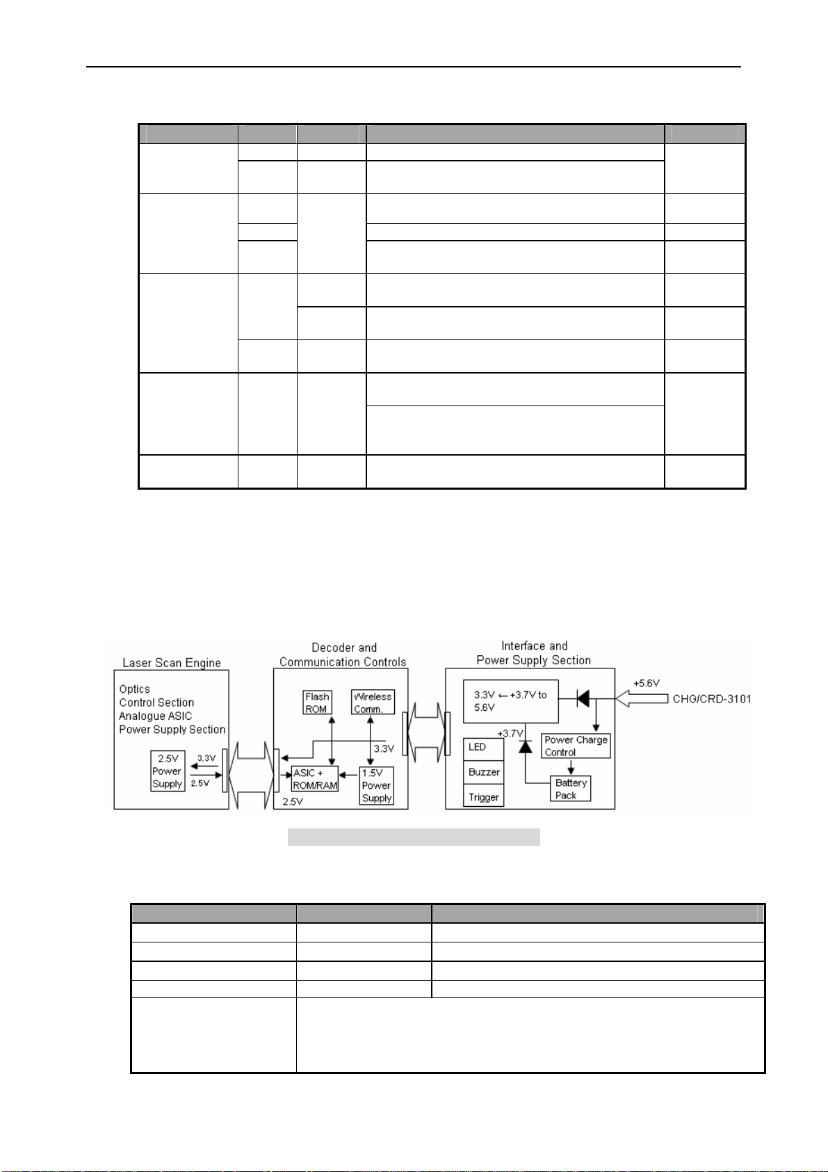
4-1. Buzzer and LED Display
OPR-3101 notifies its operation status with LED and buzzer.
Status Color Display Operating Status Buzzer
Red Lighting Shows that the scanner is being charged.
Charging
Scanning
Wireless
Connection
Wireless
Disconnected
Low Battery
Level
Green Lighting
Blue
Red Shows a failure or error in data transmission.
Green
Blue
Red Lighting
Red Lighting
Red Blinking
Blinking
Blinking
Lighting
The light changes to green from red when
charging is completed.
Shows a successful completion of scanning or
data transmission.
Shows that the scanned data is being stored
to the memory of the scanner.
Shows that the scanner is making a
connection to wireless communication line.
Shows a successful completion of making
connection to wireless communication line.
Shows a failure or error in making connection
to wireless communication line.
Shows that the scanner has disconnected the
wireless communication line.
Shows that the wireless communication is
disconnected because the scanner is outside
the communication range.
Shows that the battery level is becoming very
low. The scanner must be charged.
---
Trrr
Pip
Pip
---
Trrr Pip
Pip Pip Pip
Trrr
---
5. Electrical Specifications
5-1. Configuration
OPR-3101 consists of a laser scan engine, which converts scanned data into analog
signals and outputs the data, a decode and communication section, which decodes the
data and controls the system, a power supply section and an interface section.
5-2. Current Consumption
Parameter Specifications Notes
Idle 1
Idle 2
In Use (Ave.)
Maximum Consumption 220 mA Maximum consumption in operating state.
Testing Conditions
Figure 2: Configuration of OPR-3101
30 mA (typ.) Without connection to communication line.
35 mA (typ.) With connection to communication line.
165 mA When scanning, communicating, or lighting LEDs.
- Power Supply Voltage: 3.7 V
- Operating Temperature: 25 degrees C
- Current consumption in operating state was measured while operating
the scanner in test mode.
6
Page 10
OPR-3101 SS07028
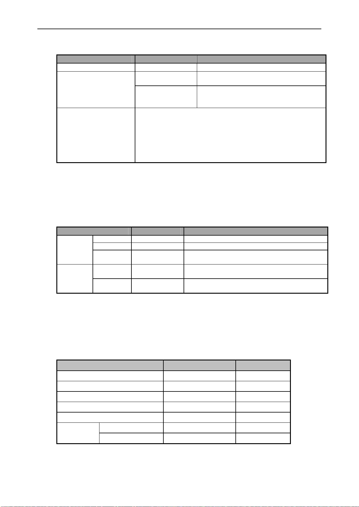
5-3. Charging Current
Parameter Specification Note
CHG-3101 while Charging 500 mA or lower
500 mA or lower
CRD-3101 while Charging
200 mA or lower
- Operating Temperature: 25 degrees C
- Charging Temperature: 0 to 40 degrees C
- Battery charging operation may be stopped when the scanner is
Testing Conditions
charged at the temperature higher than 40 degrees C.
- Battery charging operation may be stopped when the power
supply voltage impressed to the charging terminals exceeds the
range of 3 to 6 V.
AC adaptor (output: 6 V, 750 mA)
When connected to RS-232C
(when using AC adaptor)
When connected to USB.
Bus power class: Hi-POWER / 500 mA
Nominal charging current: 500 mA。
Note: Model names of AC adaptors dedicated to CHG-3101 and CRD-3101.
- Model for OSE and OPTICON: GP-ACGN13T-K4-2
- Model for Japan and North America Market: GP-ACGN13U-K4-2
5-4. Battery Life and Charging Time
Parameter Specification Note
Idle 1 About 55 hours Without connection to communication line.
Battery
Life
Charging
Time
Idle 2 About 48 hours With connection to communication line.
In Use About 25 hours
Charging
Time 1
Charging
Time 2
About 5 hours
About 10 hours
Without connection to communication line and
scanning once in every 5 seconds.
When using CHG-3101 or CRD-3101 and
connected to RS-232C.
When using CRD-3101 and connected to USB (bus
power supply).
Note: Battery life may be shorter than specified above when the quality of the battery pack
is degraded.
6. Optical Specifications
6-1. Laser Scanning Specification
Parameter Specification Note
Light-emitting Element Red laser diode
Emission Wavelength 650 ± 10 nm at 25 degrees C
Light Output
Scan Method Bi-directional
Scan Rate 100±20 scan/sec
Scan Angle 54±5 deg
Scan Angle
Effective Scan Angle 44 (Min) deg
≤ 1.0 mW
Class 2
7
Page 11
OPR-3101 SS07028
6-2. Laser Scanning Standard
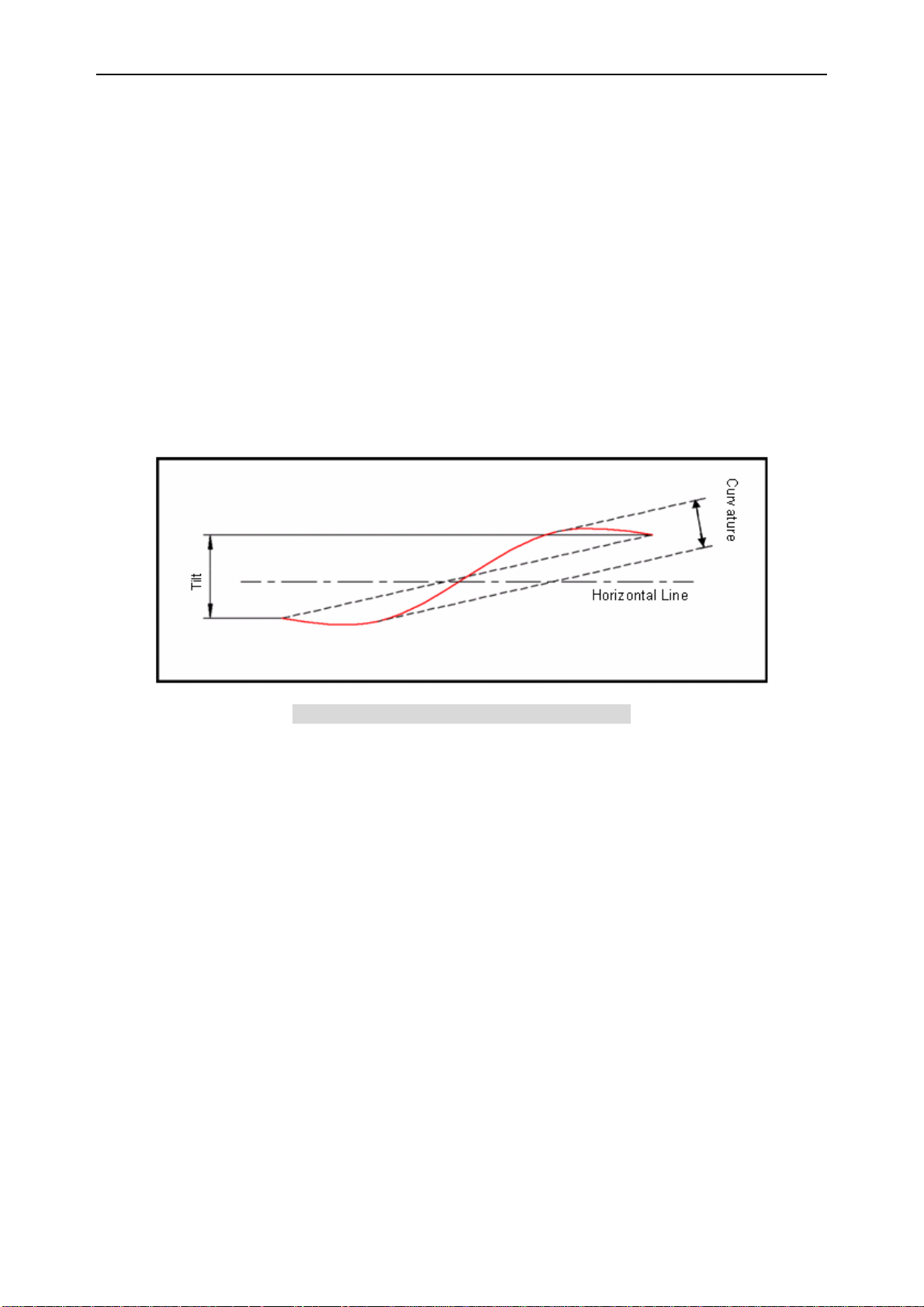
6-2-1. Laser Scanning Tilt
Laser scanning tilt is the vertical difference between both ends of a laser scan line.
Measure it in the middle of the laser scan line.
• Up to 1.2 degrees angle in vertical direction from the scan origin (mirror motor).
• Up to 3.1 mm at 150 mm from the scan origin.
6-2-2. Scanning Curvature
The maximum difference between the laser scan line and the line between both ends
of the laser scan line. Measure it in the middle of the laser scan line.
• Up to 1.27 degrees angle in vertical direction from the scan origin (mirror motor).
• Up to 3.3 mm at 150 mm from the scan origin.
Figure 3: Laser Scanning Tilt and Curvature
7. Technical Specifications
The conditions for technical specifications are as follows, unless otherwise specified in each
section.
Conditions
Ambient Temperature and Humidity 21 ºC/70 ºF, 60% RH
Ambient Light 500 to 900 lx
Background Barcode = black, Space = white, Margin = white,
Background of label = black
Power Supply Voltage 3.7 V
Decoding Test Approve the performance when scanning is successful in all ten tests.
(Scanning is deemed successful when completed in 0.5 second or less.)
7-1. Print Contrast Signal (PCS)
0.45 or higher (over 70% of reflectivity of space and quiet zone).
8
Page 12
OPR-3101 SS07028
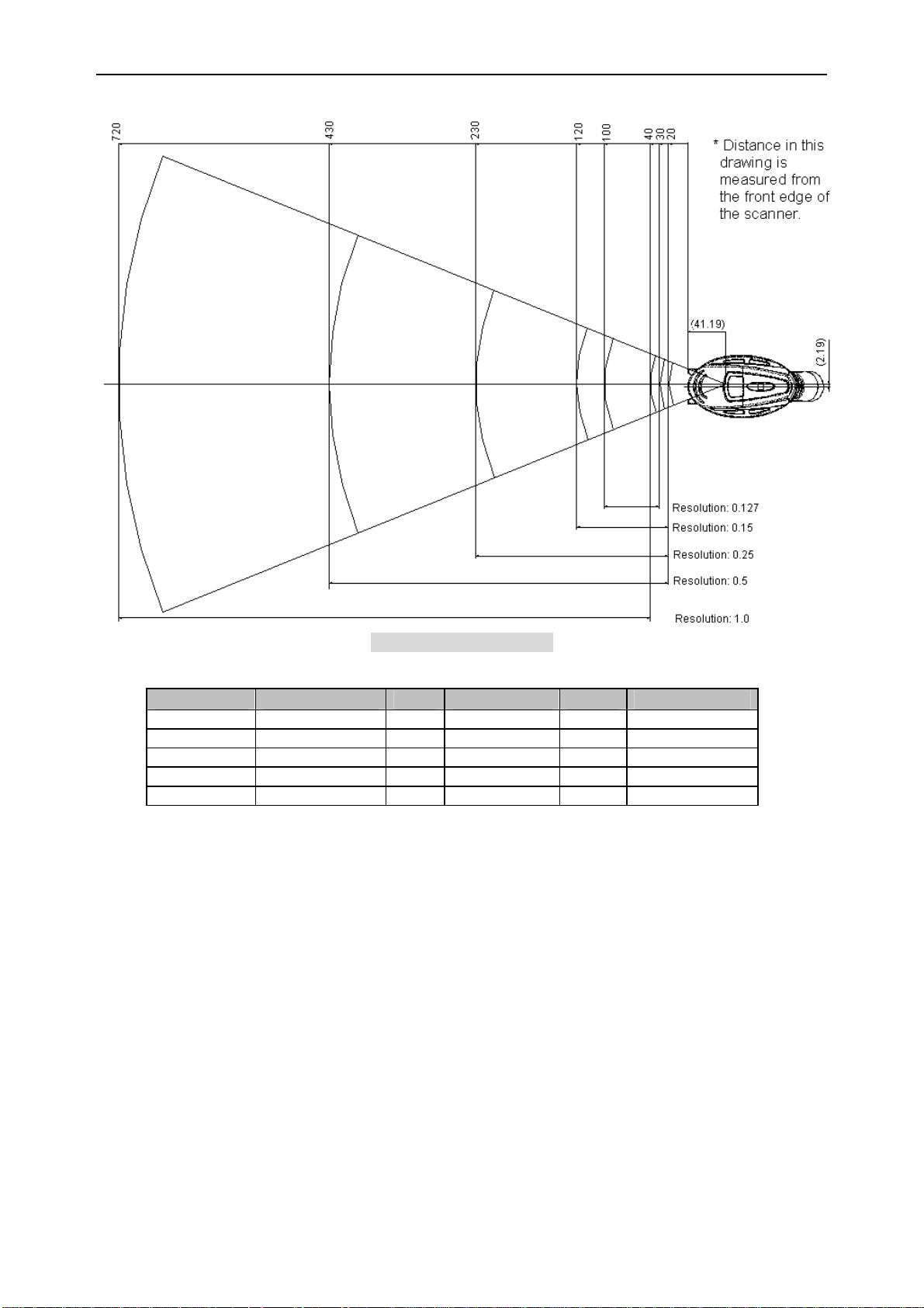
7-2. Depth of Field and Resolution
Figure 4: Depth of Field
Resolution Symbology PCS Quiet Zone Digits Depth of Field
1.0 mm Code 39 0.9 25 mm 1 40 to 720 mm
0.5 mm Code 39 0.9 18 mm 3 20 to 430 mm
0.25 mm Code 39 0.9 10 mm 8 20 to 230 mm
0.15 mm Code 39 0.9 7 mm 10 20 to 120 mm
0.127 mm Code 39 0.9 5 mm 4 30 to 100 mm
Conditions:
Barcode Sample: OPTOELECTRONICS Test Sample
N/W Ratio: 1:2.5
Angle: α = 0°, β = 15°, γ = 0°
Curvature:
R = ∞
9
Page 13
OPR-3101 SS07028
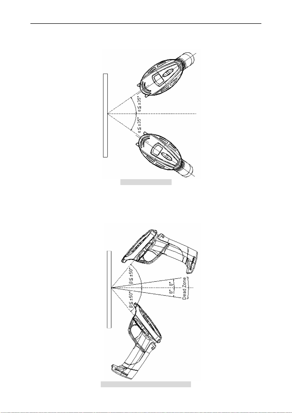
7-3. Pitch, Skew and Tilt
7-3-1. Pitch Angle
α ≤ ±35°
Figure 5: Pitch Angle
7-3-2. Skew Angle
β ≤ ±50° (Excluding dead zone)
Dead Zone: β ≤ ±8° (There are some areas in which decoding fails due to specular
reflection.)
Figure 6: Skew Angle and Dead Zone
10
Page 14
OPR-3101 SS07028
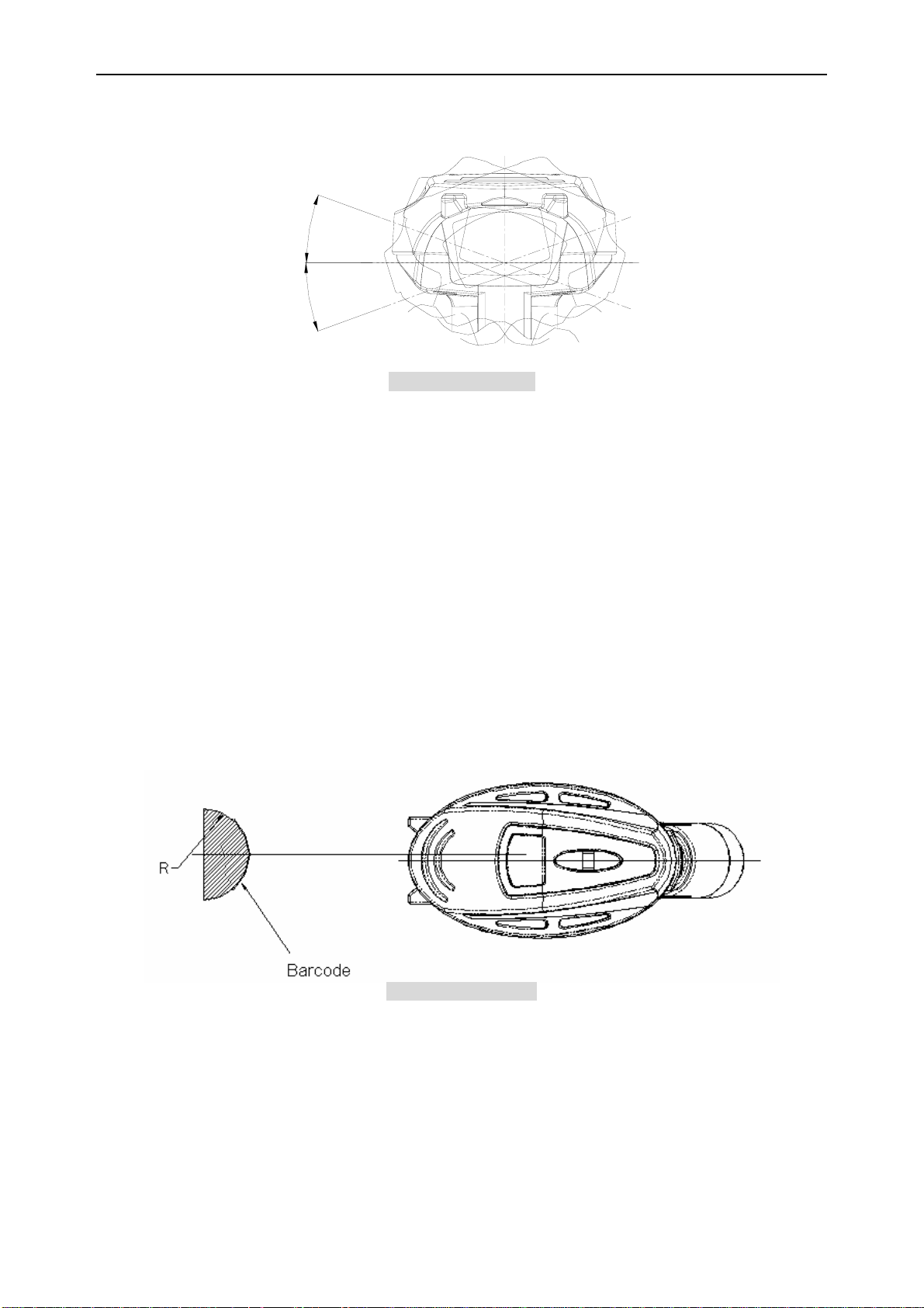
7-3-3. Tilt Angle
γ ≤ ±20°
°
0
2
=
γ
°
0
2
=
γ
Figure 7: Tilt Angle
Conditions:
Barcode Sample: OPTOELECTRONICS Tes t Sa m p le
Label: <Pitch Angle, Skew Angle, Dead Zone>
PCS = 0.9, Resolution = 0.25 mm, Symbology = 9-digit Code-39,
Quiet Zone = 10 mm, N/W Ratio = 1:2.5
<Tile Angle>
PCS = 0.9, Resolution = 0.26 mm, Symbology = 13-digit JAN,
Quiet Zone = 10 mm
Distance: 60 mm from the edge of the scanner
Angle: <Pitch Angle > Skew Angle β = +15°, Tilt Angle γ = 0°
<Tile Angle > Pitch Angle α = 0°, Skew Angle β = +15°
<Skew Angle, Dead Zone> Pitch Angle α = 0°, Tilt Angle γ = 0°
Curvature: R = ∞
7-4. Curvature
With 8-digit JAN barcodes, decoding performance is guaranteed when R ≥ 15mm.
With 13-digit JAN barcodes, decoding performance is guaranteed when R ≥ 20mm.
Figure 8: Curvature
Conditions:
Barcode Sample: OPTOELECTRONICS Tes t S a m p l e
PCS = 0.9, Resolution = 0.26mm, 9-digit Code 39, Quiet Zone = 10mm
Distance: 60 mm from the edge of the scanner
Angle: Skew Angle β = +15°
11
Page 15

OPR-3101 SS07028
8. Wireless Connection
The wires interface used by the OPR-3101 complies with Bluetooth Ver. 2.0. SPP (Serial Port
Profile) is supported to enable OPR-3101 to communicate with other Bluetooth devices
equipped with the same profile.
・Supported Protocol Stack
RF (Radio Frequency Protocol)
BB (Base Band Protocol)
LM (Link Manager Protocol)
L2CAP (Local Link Control and Adaptation Protocol)
RFCOMM (RS-232C Emulation)
・Supported Profile
GAP (Generic Access Profile)
SPP (Serial Port Profile)
・Connection Configuration
Connect one OPR-3101 to one host system
*Note: OPR-3101 does not support multiple channel communication.
・Operation Mode in Communication
Master: OPR-3101
Slave: CRD-3101 and other Bluetooth devices
・Low Power Mode
Sniff mode is not supported.
・Security and Encryption
Security and encryption settings are available.
・Communication Range
Approximately 10 meters.
*Note: The communication range of OPR-3101 may differ depending on the
environmental conditions. Especially, when there is a obstacle between the
OPR-3101 and host, the communication range of OPR-3101 may be shortened.
12
Page 16
OPR-3101 SS07028
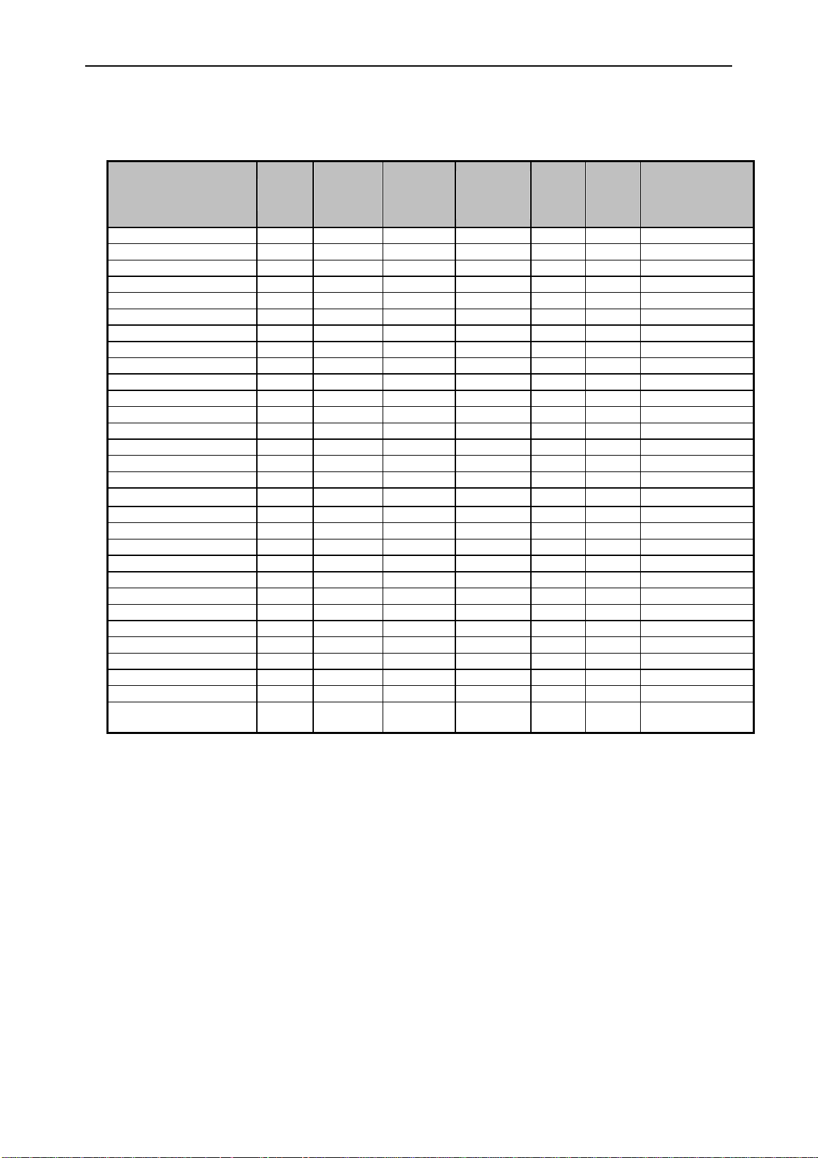
9. Default Settings
The OPR-3101 units are set to the following default settings [SO] at the time of shipment.
Default Setting 1: Readable Codes
Transmit
Code type Reading
code
length
UPC-A X --- CR
UPC-A Add-on X X --- CR
UPC-E X --- CR
UPC-E Add-on X X --- CR
EAN-13 X --- CR
EAN-13 Add-on X X --- CR
EAN-8 X --- CR
EAN-8 Add-on X X --- CR
Code 39 X X --- CR Not transmit ST/SP
Code 39 Trioptic X --- --- --- CR Not transmit ST/SP
NW-7(Codabar) X X --- CR Not transmit ST/SP
Industrial2of5 X X --- CR
Interleaved2of5 X X --- CR
Code 93 X X --- CR
Code 128 X X --- CR
EAN-128 X X X --- CR
S-Code X X --- CR
MSI/Plessey X CD1 CD1 --- CR
UK/Plessey X --- CR
Telepen X X --- CR
Matrix2of5 X X X --- CR
Chinese Post Matrix2of5 X X X --- CR
IATA X X --- CR
RSS-14 X X --- CR
RSS-limited X X --- CR
RSS-expanded X X --- CR
PDF417 X X --- --- --- CR
MicroPDF417 X X --- --- --- CR
Code 11 X X X --- CR
Korean Postal Code
(Code 3of5)
X X X --- CR
Transmit
CD
Calculate
CD
Prefix
settings
Suffix
settings
Transmit others
Notes:
1) In the Reading column, “
2) In the Transmit Code Length column, “
” means Enable Reading and “X” means Disable Reading.
” means Transmit Code Length and “X” means “Do
Not Transmit Code Length.
3) In the Transmit CD column, “
” means Transmit Check Digit and “X” means Do Not
Transmit Check Digit.
4) In the Calculate CD column, “
” means Calculate Check Digit and “X” means Do Not
Calculate Check Digit.
5) In the Prefix Settings column, “
” means No Prefix Setting.
13
Page 17
OPR-3101 SS07028
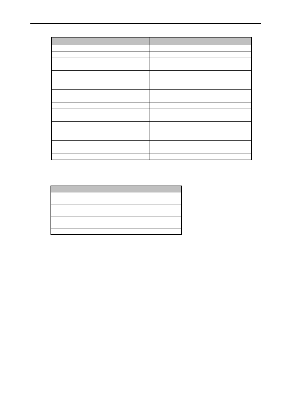
Default Setting 2: Read options, trigger options and buzzer options
Item Default Setting
Setting the number of characters Fixed length OFF all codes
Read mode Single read
Multiple read reset time 500 msec
Add-on wait mode 500 msec
Multiple read Disable multiple read
Multiple columns read Disable multiple columns read
Redundancy*1 Read 1 time, redundancy = 0
Trigger switch Enable trigger
Trigger repeat Disable trigger repeat
Auto trigger Disable auto trigger
Read time 2 seconds
Margin check Margin check normal
Buzzer durations 50 msec
Buzzer tone 3 kHz (single tone)
Buzzer loudness Maximum
Buzzer timing Buzzer before transmission
Startup buzzer Enable startup buzzer
Indicator duration 200 msec
*1: Redundancy
The following codes will be set to “read 2 times, redundancy = 1” when the number of
digits are less than following:
Code Digits
Code 39 5 and less
NW-7(Codabar) All
IATA 8 and less
Industrial2of5 8 and less
Interleaved2of5 8 and less
MSI/Plessey 4 and less
Code 11 5 and less
14
Page 18
OPR-3101 SS07028
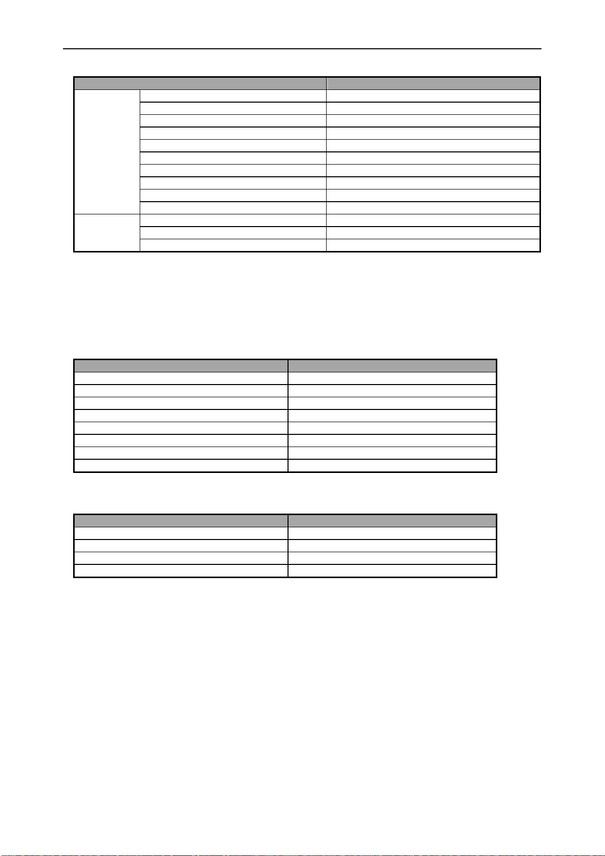
Default Setting 3-1: Wireless options
Item Setting
Default Bluetooth connection RS-232C cradle connection
Data memorizing Disabled
Trigger connection options Disabled
Press trigger switch time to connect Disabled
Wireless
Options
Bluetooth
Options
Press trigger switch time to disconnect Disabled
Auto disconnect Disabled
Auto reconnect 5 minutes
ACK/NAK No response
ACK/NAK timeout 100 ms
PIN-code label 4 last digits of Bluetooth device address
Bluetooth address auto connect Enabled
Authentication Enabled (automatically done)
Encryption Enabled
* The default interface between the CRD-3101 and host is set to RS-232C.
* When using USB connection between the CRD-3101 and host, connection must be made to
the USB-HID of the cradle.
* Do not connect to [CNPC] when using OPR-3101 and CRD-3101.
Default Setting 3-2: Settings to connect the CRD-3101 to host via RS-232C (cabled)
Item Setting
Baud rate 9600 bps
Parity bit No parity
Data length 8 bits
Stop bit 1 bit
Handshaking No handshake
ACK/NAK No ACK/NAK
Flow Control time out Indefinitely
Intercharacter delay No delay
Default Setting 3-3: Settings to connect the CRD-3101 to host via USB (cabled)
Item Setting
Keyboard language USA
Key code output Full key code
Caps Lock Control No Caps Lock
Intercharacter delay No delay
15
Page 19
OPR-3101 SS07028
10. Serial Label, Serial No., Regulations
10-1. Serial Label
These labels shown below are affixed to the scanner.
Serial Number Label: Product name, serial number and date of manufacture
Laser Caution Label: This product is a laser class 2 product.
Model Name Label: Information of all the certifications, logos and ID numbers
10-2. Accessories
The following items are packaged with OPR-3101 at the time of shipment.
- User’s manual
- Designated battery pack (1UR18500F-OEL)
Figure 9: Product Labels
16
Page 20
OPR-3101 SS07028
11. Packaging Specifications
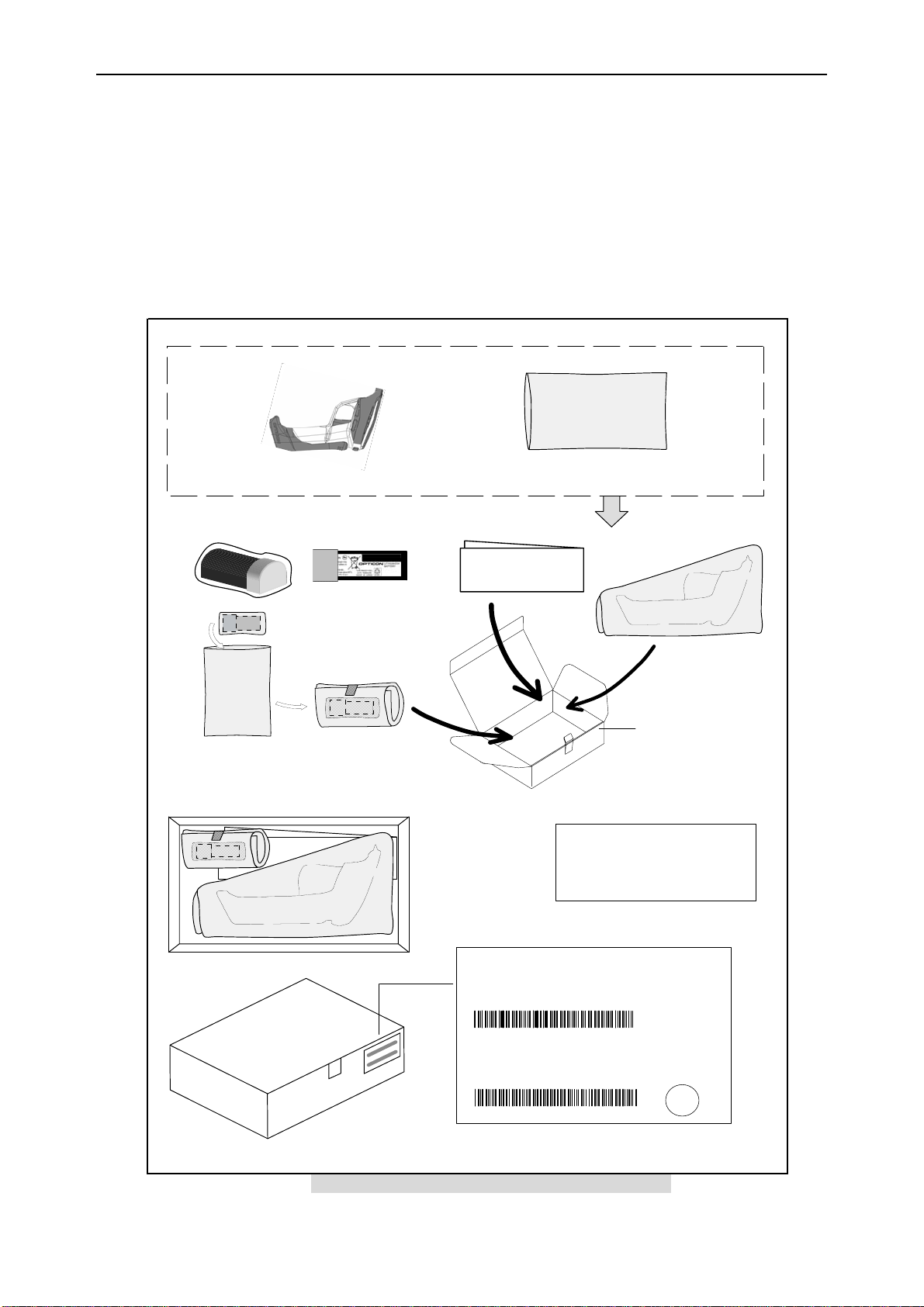
Put the OPR-3101 and the battery pack in separate protective plastic bags and put them into
an individual packaging box. 20 individual boxes can be contained in a collective packaging
box.
Note: The “Ro” mark on inner and outer packaging is to notify that this product does not use any
material, components, or parts which are restricted under RoHs. However, this document does not
have any legal weight in EU.
11-1. Individual Packaging Specifications
Dimensions: 246 x 156 x 83 (mm)
Li-ion BATTERY: 1UR18500F-OEL
(A battery is in a plastic bag.)
PROTECTION BAG G
B87004-57
PROTECTION BAG E
B85009-0 9
The back side of battery.
Stuck with a scotch tape.
USER'S MANUAL
USER'S MANUAL
(5J0062A)
BAR CODE LABEL for BOX
Model No.
OPR-3101
Spec No.
CARTON BOX
GS185996-23-1
Display for the serial-No.
from『 000001 』to 『 999999 』
Same number as the scanner.
Number of seven digits.
*Continuous Number
.
(3A0002)
MADE IN JAPAN
*UF1OPR3101*
Serial No.
△△△△△△
*
Do not fold at the Bar-Code Position, when
stick the Label on to the Corner of Box.
*
Quantity 1
Figure 10: Individual Packaging Specifications
17
Ro
Page 21
OPR-3101 SS07028
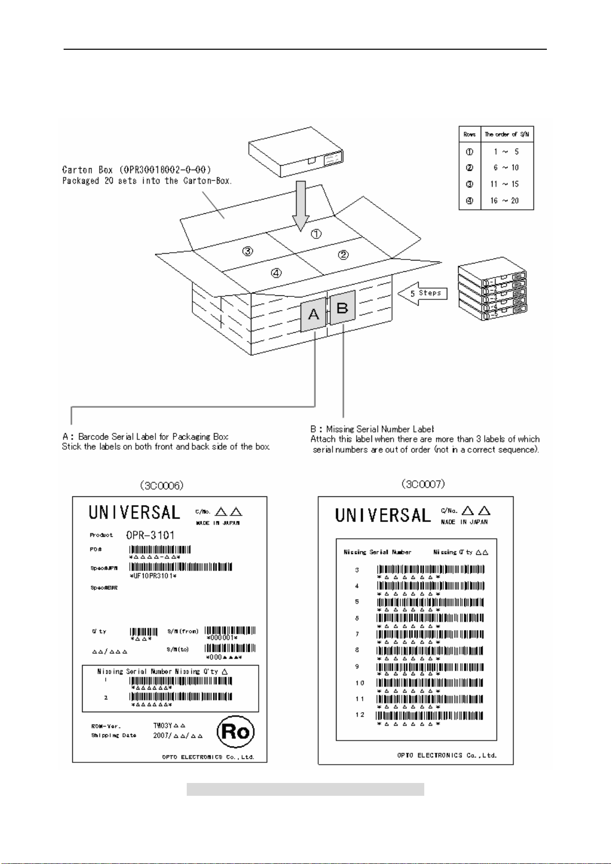
11-2. Collective Packaging Specifications
Dimensions: 507 x 324 x 435 (mm)
Internal Dimensions: 497 x 317 x 417 (mm)
Figure 11: Collective Packaging Specifications
18
Page 22
OPR-3101 SS07028
12. Environmental Specifications
12-1. Operating Temperature and Humidity
-10 to 60 degrees C (0 to 40 degrees C while charging the battery)
5 to 95 % RH (non condensing)
* Battery charging operation may be stopped when the scanner is charged at the
temperature higher than 40 degrees C.
12-2. Storage Temperature and Humidity
-20 to 60 degrees C
5 to 95 % RH (non condensing)
12-3. Ambient Light Immunity
The scanning performance is guaranteed when the range of luminance on a barcode
surface is between zero and the following values.
Incandescent Light 4,000 lx
Fluorescent Light 4,000 lx
Sunlight 80,000 lx
Conditions:
Barcode Sample: OPTOELECTRONICS Tes t S a m p l e
PCS = 0.9, Resolution = 0.25mm, Symbology = 9-digit Code-39,
Quiet Zone = 10mm, N/W Ratio = 1:2.5
Distance: 100 mm from the edge of the scanner
Angle: α = 0°, β = 15°, γ = 0°
Curvature: R = ∞
Power Supply Voltage: 3.7 V
Direct light or specular reflection light from a source should be prevented from entering the
acceptance area.
Figure 12: Ambient Light Immunity
19
Page 23
OPR-3101 SS07028
12-4. Dust and Drip proof
OPR-3101 complies with IEC IP-54
12-5. Electrical Characteristics
- Withstand Voltage: AC 1500 V/ per 60 seconds, 10mA or less
- Insulation Resistance: DC 500 V, 2 MΩ or higher
- Current Leakage: 250 μA or less / AC 250 V 60 Hz
- Power Line Noise Immunity: ± 1kV and higher
- Static Electricity Noise Immunity:
No destruction found: ± 15kV (air or direct discharge)
No malfunction found: ± 8kV (air or direct discharge),
±6kV (contact, direct or indirect discharge)
Note: Testing method complies with IEC-61000-4-2.
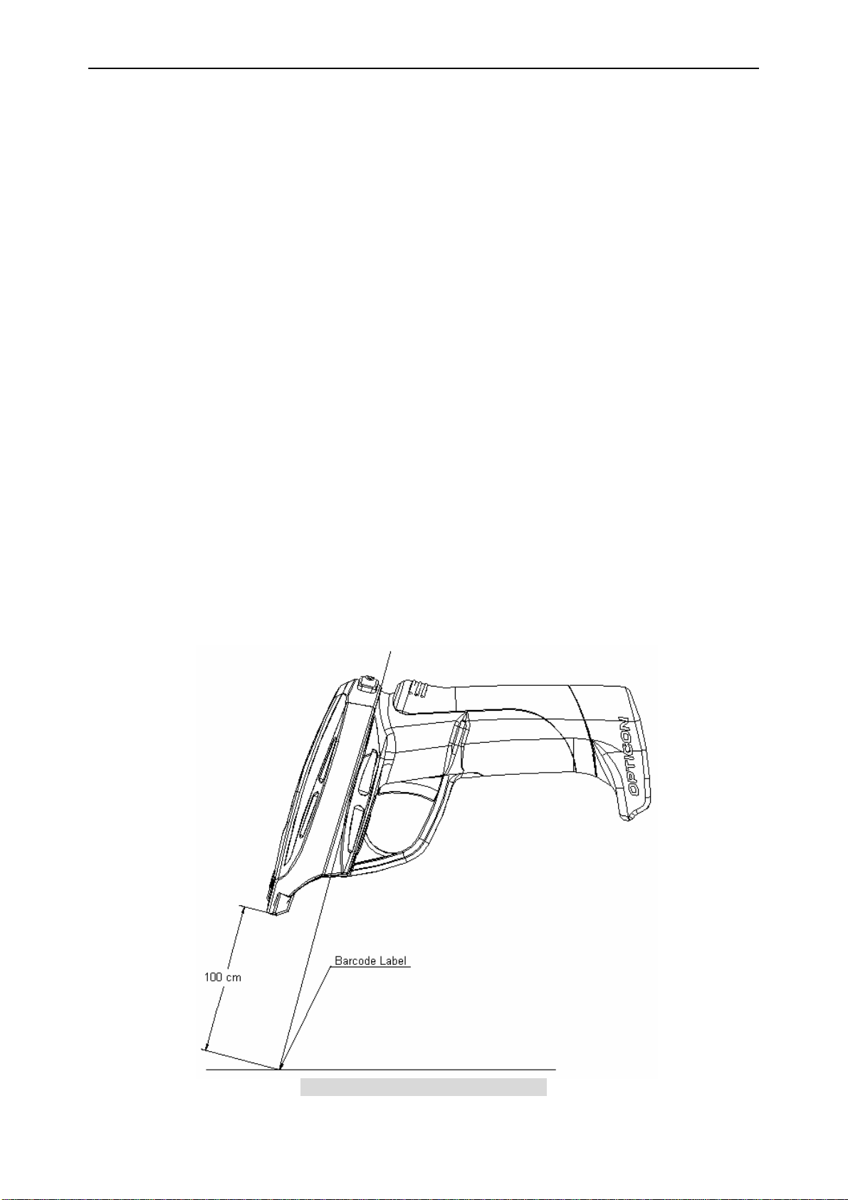
12-6. Drop Test
No defect occurred to the scanner after the following drop test.
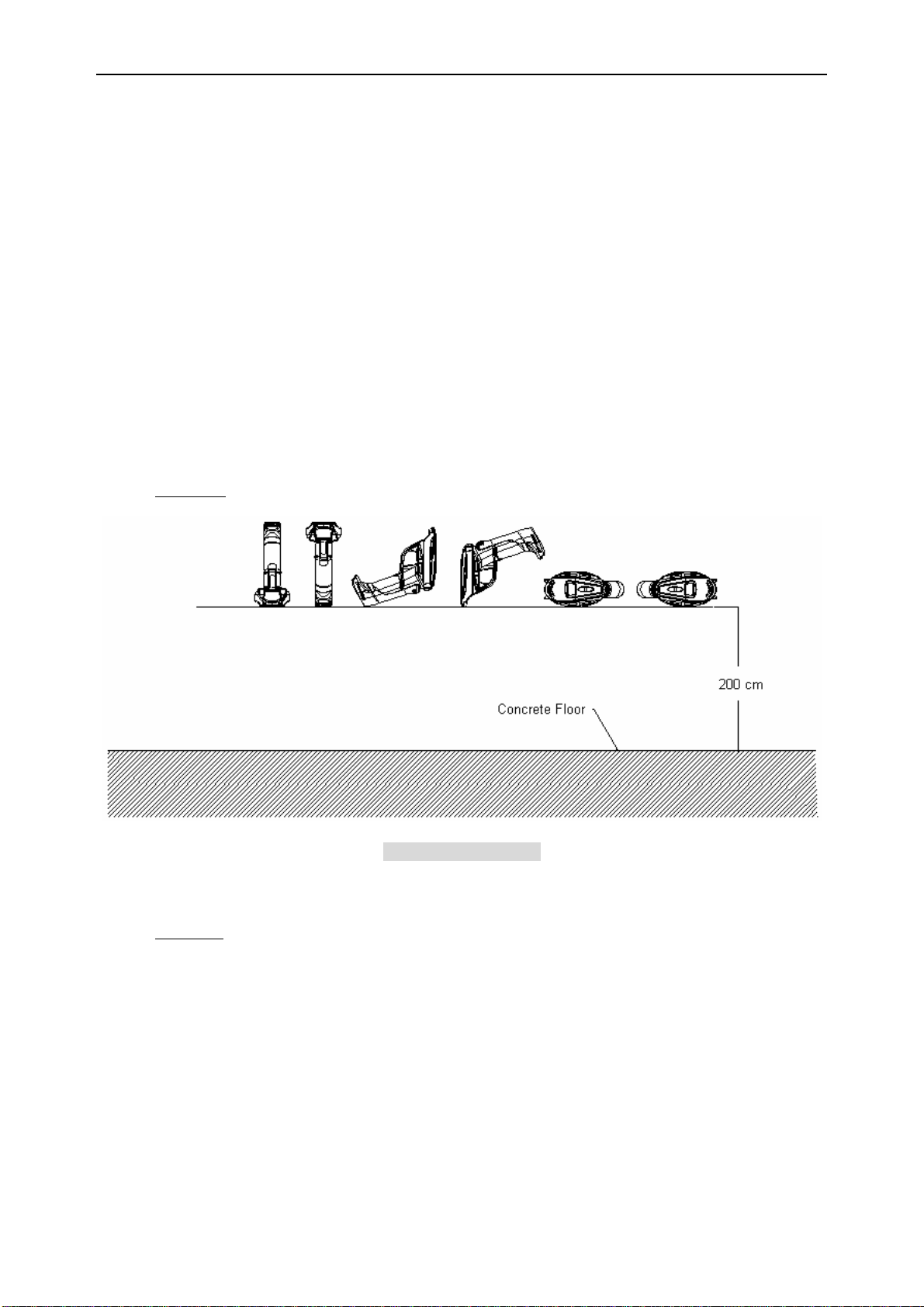
Drop Test: Drop the scanner from the height of 200 cm on to the concrete floor (three times in each
of 6 angles).
Figure 13: Drop Test
12-7. Drop Test (with individual packaging)
No defect occurred to the scanner after the following drop test.
Drop Test: Drop an individually packaged scanner from a height of 150 cm onto a concrete floor
once on its 1 corner, 3 edges and 6 sides. (10 drop tests in total.)
20
Page 24

OPR-3101 SS07028
12-8. Vibration Test
No malfunctions occurred to scanner’s performances after the following vibration test.
Vibration Test: Put the scanner in non-operating state. Increase the frequency of the vibration from
10 to 100 Hz with accelerated velocity 19.6m/S
for 10 times in each X, Y, Z direction (total hours of vibration test: 180 minutes).
2
(2G) and sweep for 6 minutes. Repeat this routine
13. Reliability
MTBF: 48,000 hours (OPR-3101 excluding its laser scan engine)
10,000 hours (laser scan engine used for OPR-3101)
Note: Foregoing MTBF values are calculated based on the idea of operating OPR-3101 in
guaranteed environments without subjecting it to electric or mechanical shocks.
Note: Foregoing MTBF values does not include the average MTBF of the battery pack
used for OPR-3101.
14. Warranty
14-1. Warranty period
OPTOELECTRONICS Co., Ltd. warrants that this product is free of defects or
malfunctions for a period of twelve (12) months from its shipment. In case of having
defects or malfunctions caused by normal usage in accordance with this specification
during the foregoing warranty period, OPTOELECTRONICS shall repair or adjust the
product free of charge.
Any repair or replacement of the product after the foregoing warranty period shall be
charged at regular repair rates.
If defects or malfunctions were caused by customer mishandling, product repairs or
replacement will be charged at regular repair rates, even during the foregoing warranty
period.
14-2. Delivery
Products for maintenance or repair shall be sent back to OPTOELECTRONICS. The
sender is responsible for all shipping costs.
14-3. Repair Timeframe
Repaired products shall be shipped back to the customer within 20 days after acceptance
by OPTOELECTRONICS.
Expedited repairs may be available, subject to terms agreed to by OPTOELECTRONICS
and the customer.
14-4. Maintenance Period
The maintenance period of this product is 5 years after its shipment.
OPTOELECTRONICS may discontinue maintenance for this product during the 5-year
maintenance period if a satisfactory replacement product or maintenance solution is
agreed to.
14-5. Other
Any additional warranty issues must be discussed with OPTOELECTRONICS on a
case-by-case basis.
21
Page 25

OPR-3101 SS07028
15. Regulatory Compliance
15-1. Laser Safety
JIS C 6802:2005 Class 2
IEC 60825-1+A:2001 Class 2
15-2. Product Safety
EN60950-1:2001/IEC60950-1:2001
15-3. EMC
EN55022/EN55024
FCC Part 15 Subpart C
This device complies with part 15 of the FCC Rules. Operation is subject To
the following two conditions: (1) this device may not cause harmful
Interference, and (2) this device must accept any interference received,
including interference that may cause undesired operation.
VCCI Class B
This is a Class B product, to be used in a domestic environment, based on the
Technical Requirement of the Voluntary Control Council for Interference from
Information Technology Equipment (VCCI). If this is used near a radio or
television receiver in a domestic environment, it may cause radio interference.
15-4. Others
Certification for Construction Design of Specified Radio Equipment
Bluetooth Logo Certification
16. Reduction of Environmental Loads
OPR-3101 complies with RoHS
RoHS: The restriction of the use of certain hazardous substances in electrical
and electronic equipment, 2002/95/EC.
22
Page 26

OPR-3101 SS07028
17. Precautions
17-1. Laser-related Caution
Please do not look directly at the laser.
Please do not point the laser at others’ eyes.
Pease do not look directly at the beam of optical instruments.
These things have the potential to damage your eyes.
17-2. Handling
Handle this product carefully. Do not subject it to any of the following:
17-2-1. Shock
Do not drop this device from a height greater than specified in this manual.
Do not swing around the scanner.
17-2-2. Temperature Conditions
Do not use the device at temperatures outside the specified range.
Do not pour boiling water on the device.
Do not expose the device to open flame.
17-2-3. Foreign Materials
Do not put the device in water.
Do not expose the device to chemicals.
17-2-4. Other
Do not disassemble this product.
Do not use the scanner near a radio or a TV. It may cause reception problems.
The scanner may not perform properly when subjected to excessive static electricity..
The scanner may not perform properly in environments when placed near a flickering
light, such as a CRT (computer monitor, television, etc.).
Do not rotate the battery cover with extreme force when fastening it.
17-3. Precautions on Radio Equipment
OPTOELECTRONICS has received Certification for Construction Design of Specified
Radio Equipment for OPR-3101. Therefore, it is not necessary to acquire license of radio
stations for its use in Japan.
Followings are prohibited under law.
・ Modify or disassemble this product.
・ Peel off the certification label from this product.
Do not use this product for following devices or in the following conditions:
・ Safety device or medical equipment developed to protect human body.
・ Environment where the outstanding damages may be caused to this scanner.
17-4. Export Administration Regulations
This product is subject to the strategically controlled exports regulated under “Foreign
Exchange and Foreign Trade Laws”. Therefore, export of this product may require an
export permission of Japanese government.
17-5. Bluetooth
• Bluetooth is trademark owned by Bluetooth SIG, Inc., U.S.A. and licensed to
23
Page 27

OPR-3101 SS07028
OPTOELECTRONICS.
• OPR-3101 supports Bluetooth wireless communication with other Bluetooth
device which has the same profile.
• OPR-3101 complies with Bluetooth Ver. 2.0. However, its communication
performance with equipments other than cradles or devices stated in this manual
is not guaranteed.
The frequency band (2.4 GHz) which is used by Bluetooth devices is also used
•
by miscellaneous other equipments. The baud rate or the communication range
of OPR-3101 may be degraded by the negative impacts of those other
equipment.
The baud rate or the communication range of OPR-3101 may be degraded by
•
obstacles, radio wave conditions or the state of the device which OPR-3101 is
communicating with.
• Communication performance of OPR-3101 may be degraded when there is a
metal item extremely close to the back of the scanner.
• Expected interference distance is within 20 cm.
17-6. Frequency Band
The frequency band of 2.4 GHz is utilized by this scanner. Read carefully the followings
before using this product.
In the frequency band of this scanner, scientific, medical and industrial devices including
microwaves are used. Also other radio stations including local private radio station for
mobile object identification requiring license for such as manufacturing lines at factories,
specific power-saving radio station requiring no license and amatuer radio station are
managed.
• Please make sure that “other radio stations” are not operated in the frequency band of
2.4 GHz before using this scanner.
• In case that radio interference occurs between this scanner and “other radio stations,”
change the service space immediately, or stop transmitting radiowave to avoid the
interference.
• If you have any questions or troubles, please contact our marketing group.
This information is subject to change without prior notice.
24
Page 28
OPR-3101 SS07028
18. Auto Trigger
The OPR-3101 has optional read options stated as follows:
(1) Manual mode: Press trigger key and scanning operation starts
(2) Multiple read mode: Scanner will stay ON for a time as set and scanning can be done
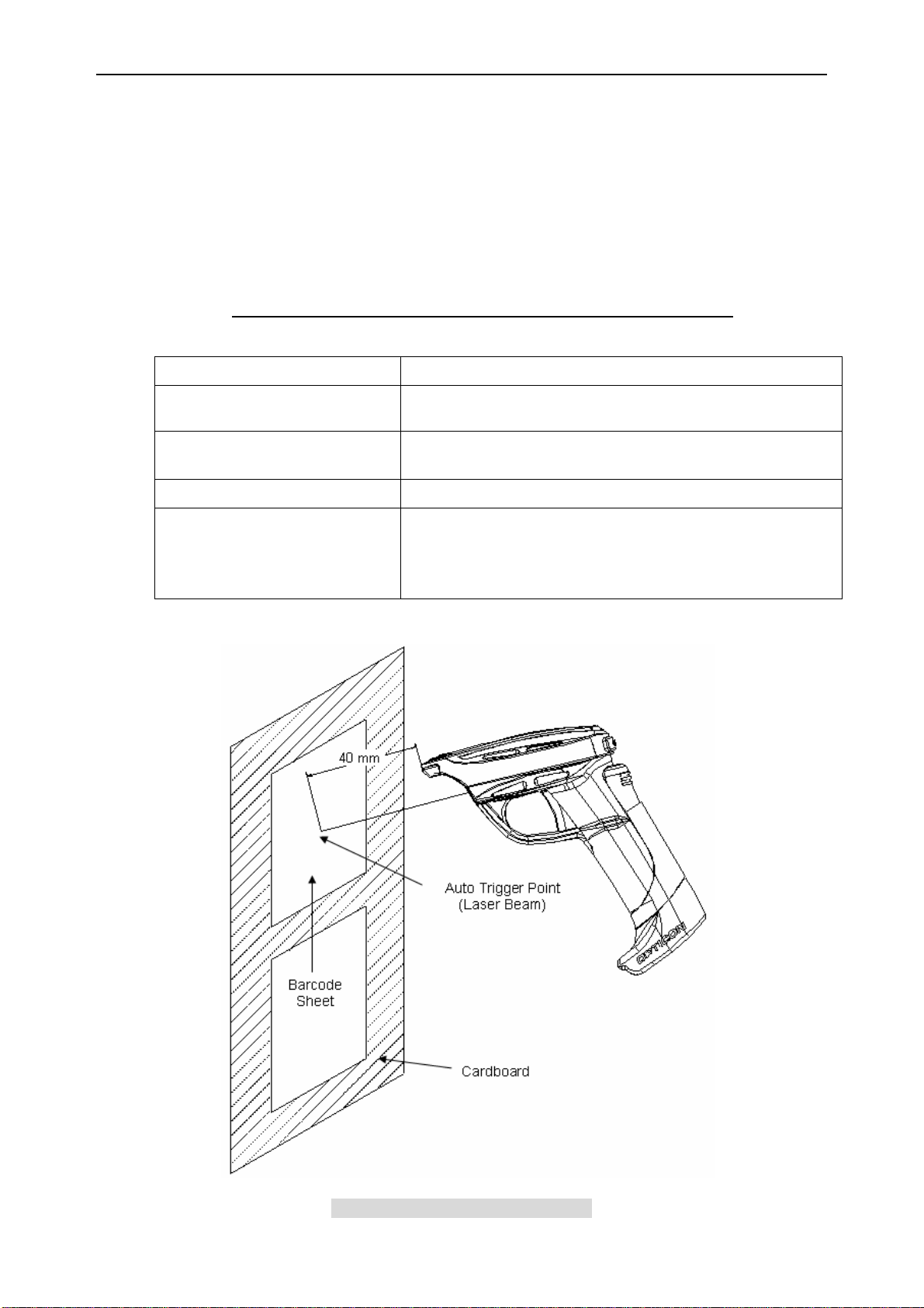
without pressing the trigger key.
(3) Auto trigger mode: Scanner starts barcode reading automatically by using sensor
detection. When enabling auto trigger, laser beam is emitted and points the auto trigger
area. The scanner starts barcode reading after detecting reflection from the surface when
the auto trigger is used.
Auto trigger distance is up to 40 mm from the edge of the scanner.
CONDITIONS:
Moving Speed:
100±10mm/s (the moving direction is not specified)
Angle:
Environmental Temperature
and Humidity:
Environmental Illuminance:
Conditions for the auto trigger:
Skew Angle excluding Pitch Angle and Dead Zone specified
in 7-3. Pitch, Skew and Tilt.
Room temperature and humidity
500 to 900 lx
1. Barcode sheet: OPTOELECTRONICS Test Sheet (white)
Background: OPTOELECTRONICS Test Sheet (black)
2. Barcode sheet: OPTOELECTRONICS Test Sheet (black)
Background: OPTOELECTRONICS Test Sheet (white)
Figure 14: Auto Trigger Operation
25
Page 29
OPR-3101 SS07028
Appendix: Mechanical Drawings
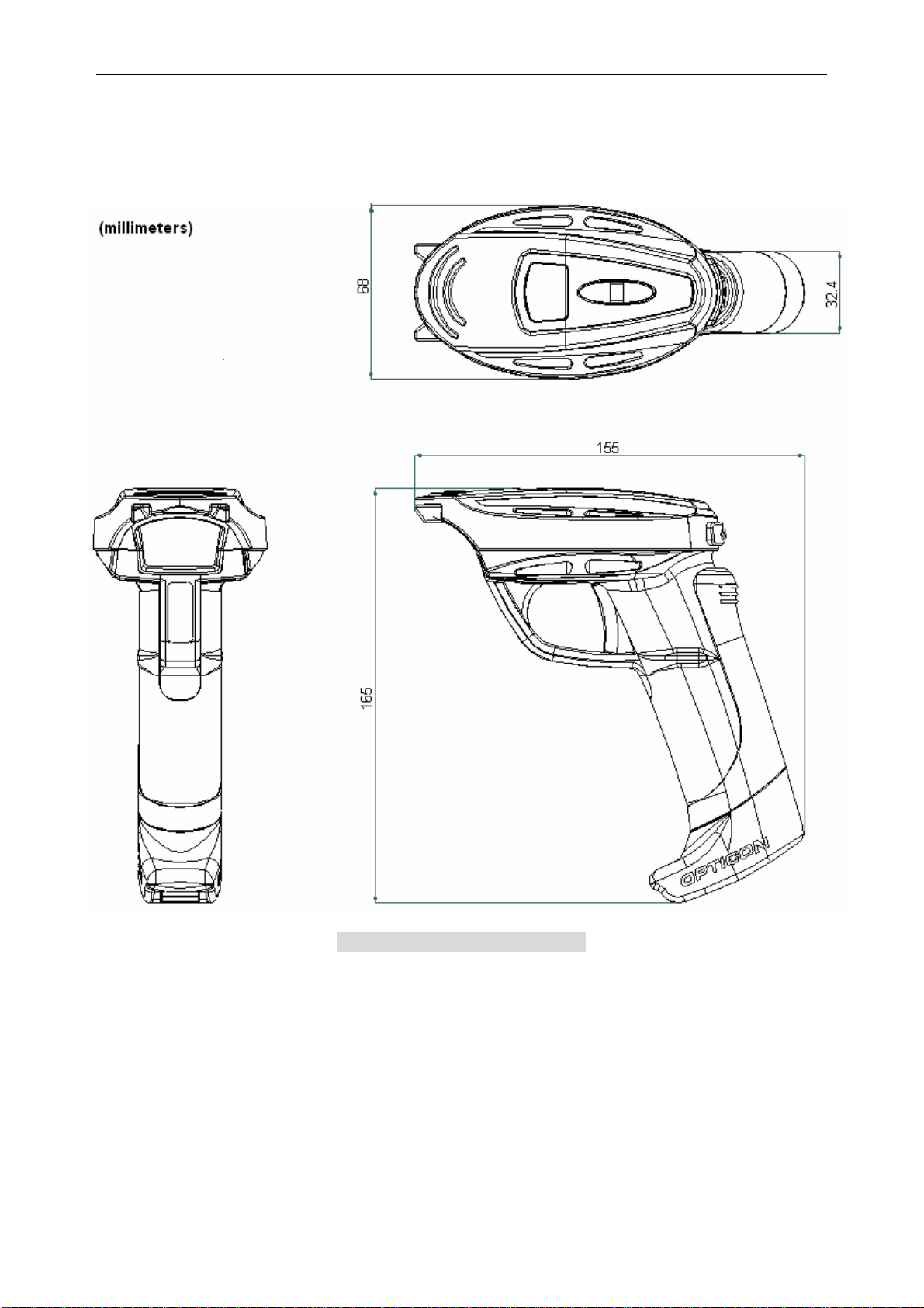
Dimensions: 165 (H) x 68 (W) x 155 (D)
(Excluding boss)
Figure 15: Mechanical Drawings
26
 Loading...