


Nokia Asha 308, Asha 309, RM838, RM852, RM843 Service Manual
...Service Manual for L1 and L2
Nokia Asha 308
(RM-838 / RM-852) Dual-SIM
Nokia Asha 309
(RM-843 / RM-844) Single-SIM
Key features
S40 operating system with Full Touch UI
Dual SIM (Nokia Asha 308) / Wi-Fi (Nokia Asha 309)
Capacitive touch screen
EA Games Gift (40 free games)
Version 1.0
Check the repair policy before performing any mechanical repair on Service Level 1&2!
Exploded view |
Disassembly steps |
Assembly hints |
More |
More |
More |
Service devices |
Product controls and interfaces |
Service concept |
More |
More |
More |
Solder components
More
©2012 Nokia | Nokia Internal Use only | All Rights Reserved.

Service Manual Level 1 and 2
Nokia Asha 308
Nokia Asha 309
Exploded view
RM-838, RM-852 / RM-843, RM-844
Version 1.0
1 A-COVER ASSEMBLY
(I0001 - I0003)
A-COVER
I0001
EARPIECE
I0003
UI FRAME
I0005
|
LIGHT SWAP PWB |
|
I0007 |
|
CAMERA |
|
I0011 |
3 |
D-COVER ASSEMBLY |
(I0012 - I0018) |
|
|
AV JACK |
|
I0014 |
|
DC JACK |
|
I0015 |
|
SIM DOOR |
|
I0016 |
SCREW TORX+ SIZE 4
M1.4 x 4.5
I0020
B-COVER
I0021
v1.0
TOUCH PANEL
I0002
DISPLAY
I0004
LIGHT SWAP PACKAGE |
2 |
|
(I0006 - I0010) |
||
DOMESHEET |
|
|
I0006 |
|
|
FEM SHIELDING LID |
|
|
I0009 |
|
|
BB SHIELDING LID |
|
|
I0008 |
|
|
ANTENNA MODULE ASSEMBLY |
4 |
|
(I0012, I0013) |
|
|
IHF SPEAKER |
|
|
I0012 |
|
|
ANTENNA MODULE |
|
|
I0013 |
|
|
D-COVER
I0018
MICRO SD CARD DOOR
I0017
TYPE LABEL
I0010
SCREW TORX+ SIZE 5
M1.4 X 2.7
I0019
Only available |
Not reuseable |
Repair/swap |
as assembly |
after removal |
only in level 3 |
©2012 Nokia | Nokia Internal Use only | All Rights Reserved.
Service Manual Level 1 and 2
Nokia Asha 308
Nokia Asha 309
RM-838, RM-852, RM-843, RM-844
Version 1.0
Disassembly steps
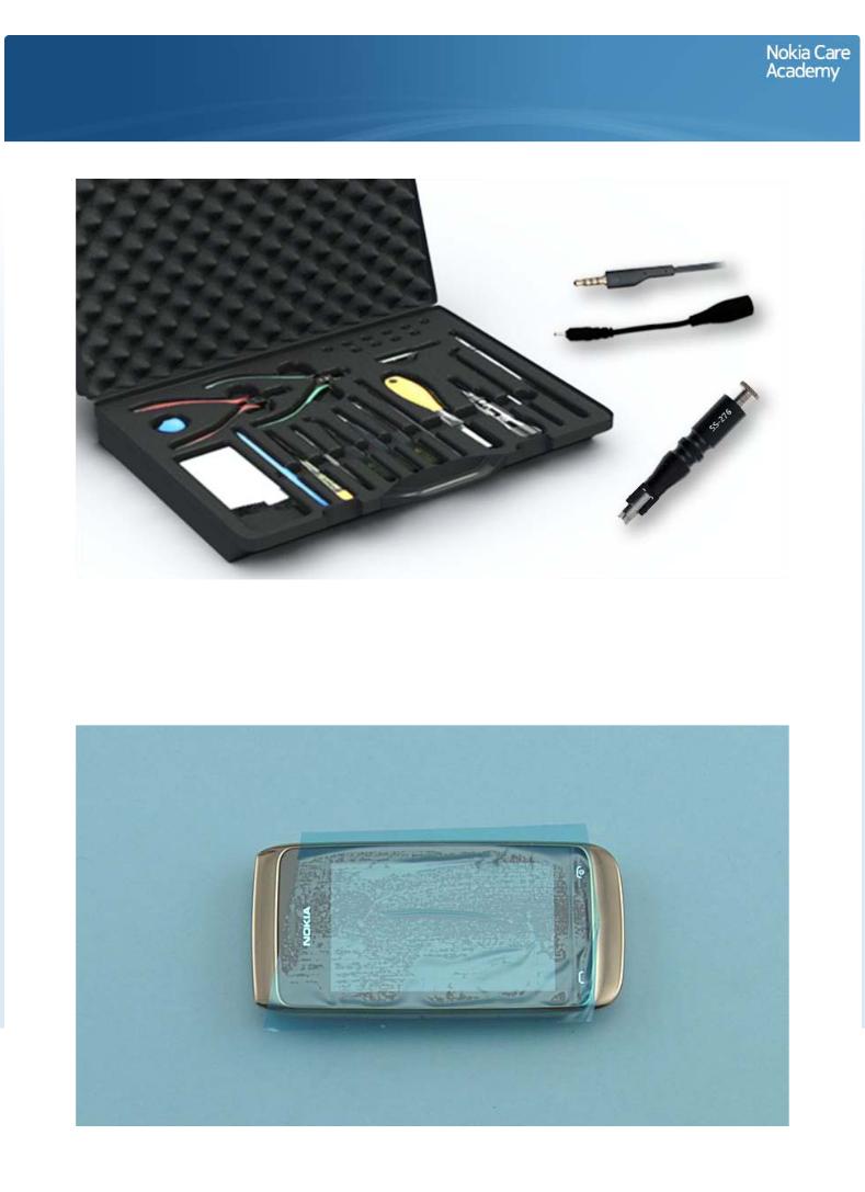
For disassembling you need the Nokia Standard toolkit version 2. You will also need a DC plug, an AV plug and the camera removal tool SS-276.
Note that the disassembly instructions are made with the Dual SIM variant (Nokia Asha 308, RM-838 and RM-852).
Protect the TOUCH WINDOW with protective film.
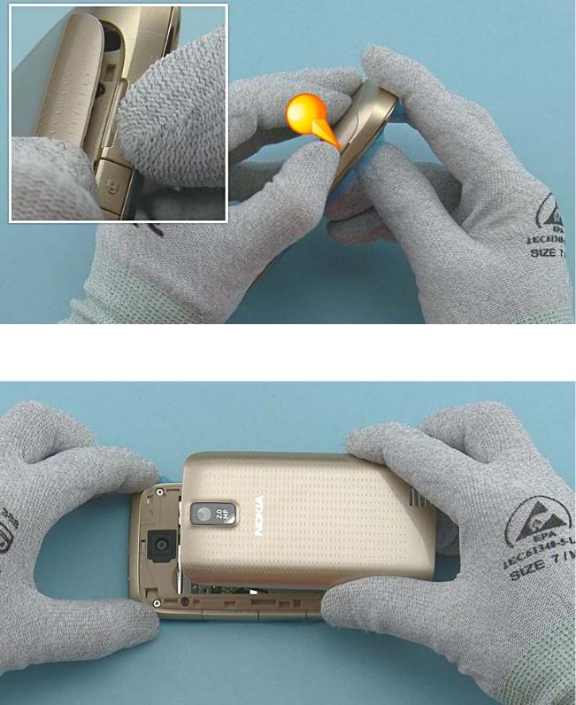
Use the opening notch to release the BATTERY COVER.
Remove the BATTERY COVER.
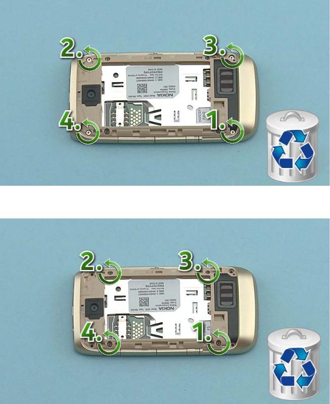
Unscrew the four Torx+ size 4 screws in the order shown. Do not use them again. Discard them.
Unscrew the four Torx+ size 5 screws in the order shown. Do not use them again. Discard them.
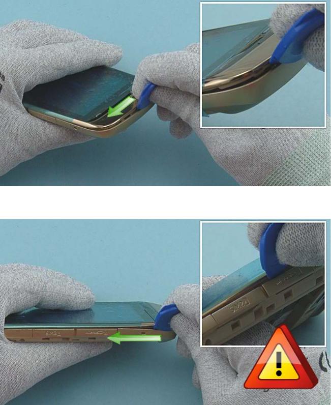
To detach the A-COVER, first release the left side of the bottom end of the A-COVER with the SRT-6.
Continue to release the A-COVER with the SRT-6 on the SIM and SD CARD DOOR side. Be careful not to damage the SIM or SD CARD DOOR while releasing the A-COVER.
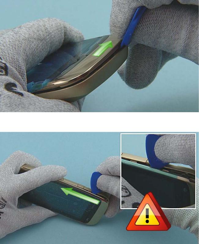
Release the right side of the bottom end of the A-COVER with the SRT-6.
Release also the LOCK KEY side with the SRT-6. Be careful not to damage the LOCK or VOLUME KEYS while releasing the A-COVER.
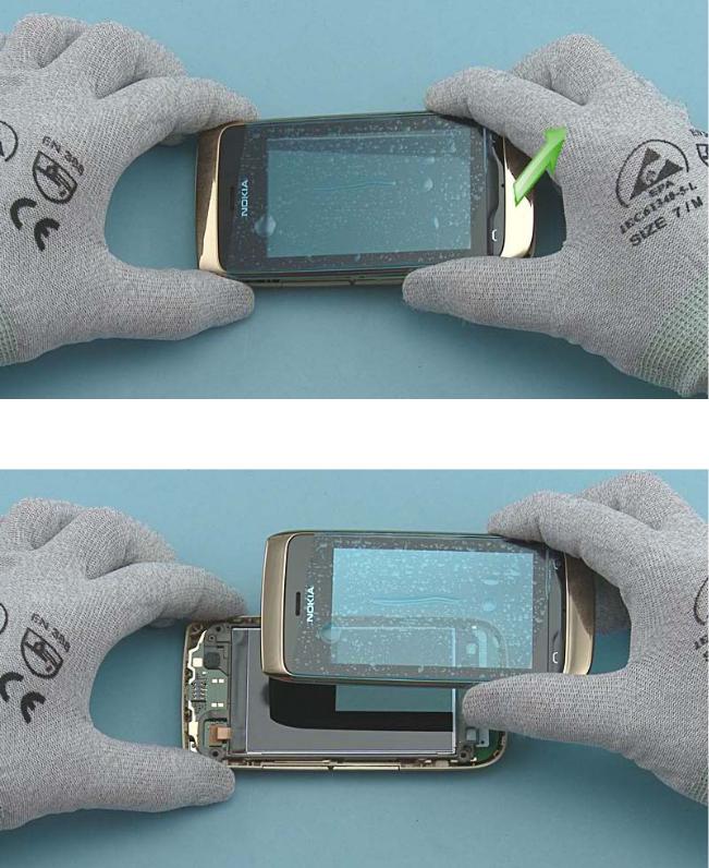
To remove the A-COVER, first lift up the bottom end and then release the top end.
Remove the A-COVER.
 Loading...