

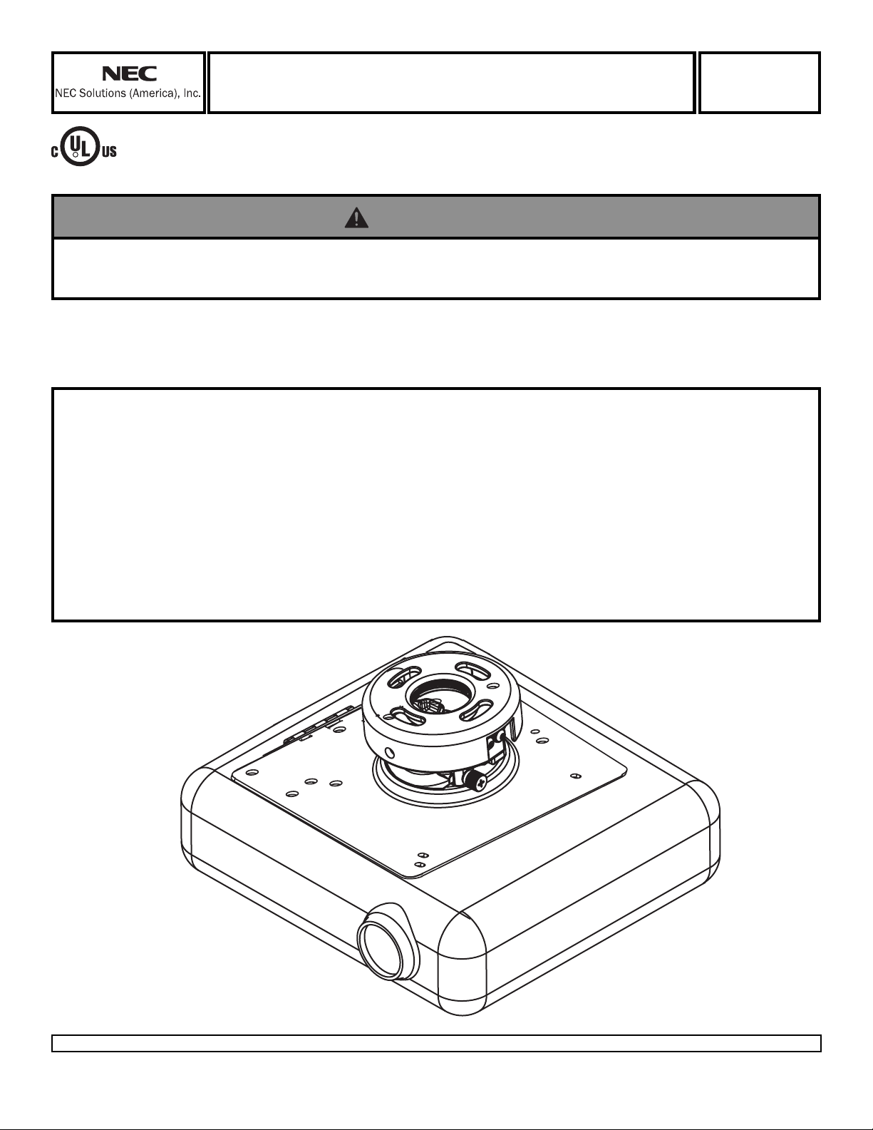
Installation and Assembly - All-in-One Projector Mount
for NEC™ Projectors
Model:
VL80CM
This product is intended for use with UL
R
Listed products and must be installed by a
qualified professional installer.
Maximum Load Capacity: 25 lb (11 kg)
Read instruction sheet before you start inst allation and assembly.
WARNING
• Installer must verify that the ceiling will safely support four times the combined weight of all attached equipment and
hardware.
NOTE: Accessories listed in the included sheet, as well as other parts, can be ordered
through Peerless by calling 1-800-729-0307 or visiting www.peerlessindustries.com.
T urn to the appropriate p age for your ceiling inst allation.
Installations:
To Wood Joist Finished Ceilings,
Exposed Wood Joists, or Wood Beam Ceilings............................................................................step 2, page 3
T o Concrete Ceilings........................................................................................................................ step 3, page 4
Applications:
Threaded Rod ..................................................................................................................................step 4, page 5
Extension Column............................................................................................................................step 5, page 5
Projector Alignment:
Adjusting Roll, Pitch, and Yaw ...................................................................................................... step 12, page 8
Visit the Peerless Web Site at www.peerlessmounts.com
1 of 8
ISSUED: 11-16-05 SHEET #: 055-9447-2
For customer care call 1-800-729-0307 or 708-865-8870.
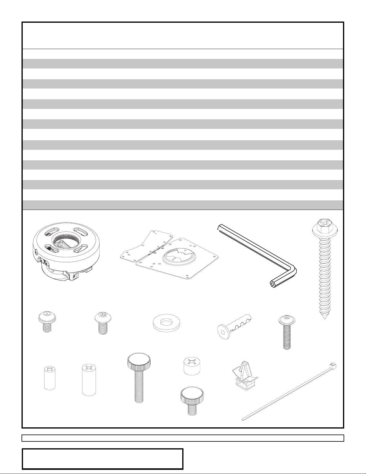
Before you start check the parts list to insure all of the parts shown are included.
Parts List
Description Qty. Part Number
A projector mount assembly 1 055-0422
B 4 mm security allen wrench 1 560-9646
C #10-32 x 3/8" serrated washer head socket pin screw 2 520-2151
D #10-32 x 1/4" socket pin screw 1 520-2196
E 1/4" flat washer 2 540-9440
F #14 x 2.5 phillips hex head wood screw 2 5S1-015-C04
G concrete anchor 2 590-0097
H adapter plate 1 055-2654
I M4 x 20 mm serrated washer head socket pin screw 2 510-2163
J .313 x .198 x .5H retaining spacer 2 590-2017
K .313 x .198 x .688H retaining spacer 1 590-2131
L M4 x 25 mm thumb screw 1 560-7142
M .313 x .198 x .25H retaining spacer 1 590-5004
N M4 x 10 mm thumb screw 1 560-7007
O cable clip 1 59 0 - 116 7
P cable tie 1 560-971 1
A
C
J
K
D
L
H
E
M
N
B
G
F
I
O
P
Note: Actual parts may appear slightly different than illustrated.
Visit the Peerless Web Site at www.peerlessmounts.com
Accessories listed in the included sheet, as well as other parts,
can be ordered through Peerless by calling 1-800-729-0307 or
visiting www.peerlessindustries.com.
2 of 8
ISSUED: 11-16-05 SHEET #: 055-9447-2
For customer service call 1-800-729-0307 or 708-865-8870.
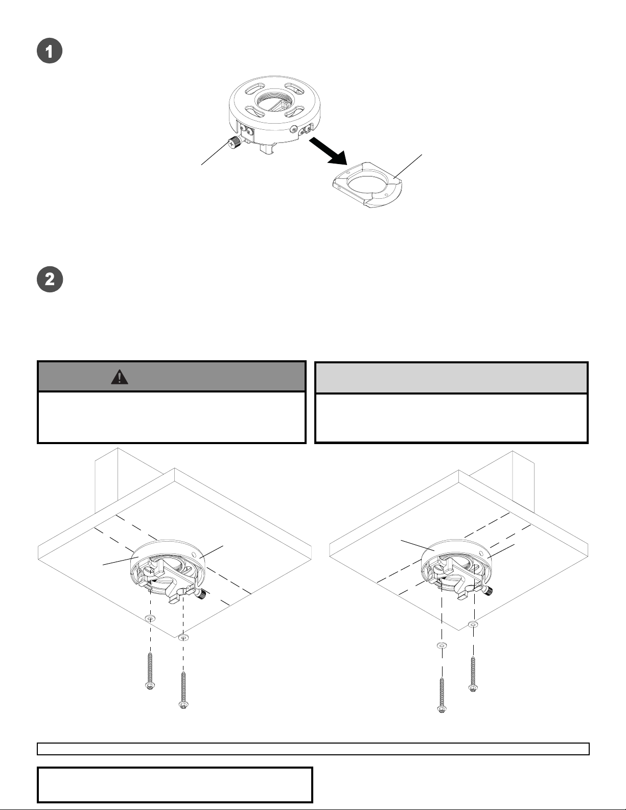
Disengage connection block from projector mount assembly (A) by unscrewing captive screw and sliding out
connection block as shown.
A
CONNECTION BLOCK
CAPTIVE SCREW
Installation To Wood Joist Finished Ceilings,
Exposed Wood Joists, or Wood Beam Ceilings
Drill two 5/32" (4 mm) dia. holes to a minimum depth of 2.5" (64 mm). Attach projector mount assembly (A) with two
#14 x 2.5" (6 mm x 65 mm) wood screws (F) and two flat washers (E) as shown in figure 1 or figure 2 depending
on joist orientation. Tighten wood screws (F) using 3/8" (10 mm) socket wrench until projector mount assembly (A)
is firmly attached.
Note: Be sure to drill holes into the joist CENTER!
Skip to step 6.
WARNING
• Installer must verify that the ceiling will safely support
the combined laod of equipment and all attached
hardware and components.
WOOD JOIST
FRONT OF
MOUNT
A
E
CAUTION
• Do not tighten screws with excessive force.
Overtightening can cause damage to mount. Tighten
screws to 40 in. • lb (4.5 N.M.) maximum torque.
A
E
FRONT OF
MOUNT
WOOD JOIST
F
figure 1
Visit the Peerless Web Site at www.peerlessmounts.com
Accessories listed in the included sheet, as well as other parts,
can be ordered through Peerless by calling 1-800-729-0307 or
visiting www.peerlessindustries.com.
3 of 8
F
figure 2
ISSUED: 11-16-05 SHEET #: 055-9447-2
For customer service call 1-800-729-0307 or 708-865-8870.

Installation to Concrete Ceilings
Drill two 1/4" (6 mm) dia. holes to a minimum depth of
2.5" (64 mm). Attach projector mount assembly (A)
using two concrete anchors (G), two flat washers (E),
and two #14 x 2.5" wood screws (F) as shown in
Illustration A and 1, 2, and 3 (below). Tighten wood
screws (F) using 3/8" (10 mm) socket wrench until
projector mount assembly (A) is firmly attached.
Skip to step 6.
CAUTION
• Do not tighten screws with excessive force.
Overtightening can cause damage to mount. Tighten
screws to 40 in. • lb (4.5 N.M.) maximum torque.
WARNING
• Installer must verify that the ceiling will safely support
the combined laod of equipment and all attached
hardware and components.
1
concrete
ceiling
G
CONCRETE CEILING
G
FRONT OF
MOUNT
A
E
F
Illustration A
Drill hole and insert anchor
2
Place ceiling plate or mount over anchor and secure
with screw
F
A
G
FOR DIRECT A TT ACHMENT TO LOAD BEARING CONCRETE
ONLY! Concrete expansion anchors are not intended for
attachment to concrete ceilings covered with a layer of plaster ,
drywall, or other finishing material. If mounting to concrete
ceiling covered with plaster / drywall is unavoidable, plaster /
drywall must be counterbored as shown below.
3
F
After repeating step one tighten all fasteners
Visit the Peerless Web Site at www.peerlessmounts.com
Accessories listed in the included sheet, as well as other parts,
can be ordered through Peerless by calling 1-800-729-0307 or
visiting www.peerlessindustries.com.
G
CUT AW A Y VIEW
4 of 8
INCORRECT
metal
bracket
plaster/
dry wall
CORRECT
concrete
For customer service call 1-800-729-0307 or 708-865-8870.
metal
bracket
plaster/
dry wall
ISSUED: 11-16-05 SHEET #: 055-9447-2
concrete

Installation to Threaded Rod
Attach projector mount assembly (A) to two 3/8-16 threaded rods (not included) using two 3/8-16 hex thin nyloninsert locknuts (not included) as shown in figure 1.1 or figure 1.2.
Skip to step 6.
3/8 -16 THREADED ROD
(NOT INCLUDED)
A
3/8 -16 HEX THIN
NYLON-INSERT
LOCKNUT
(NOT INCLUDED)
FRONT OF
MOUNT
3/8 -16 THREADED ROD
(NOT INCLUDED)
fig. 1.1
Installation to Extension Column
Screw projector mount assembly (A) onto extension column (sold separately) as shown in figure 2.1. Note: For
3/4" extension columns, reducer ACC 913 will be required as shown in figure 2.2. Tighten swivel stop screw
against extension column or reducer using security allen wrench (B). Note: Swivel stop screw is used to jam
against threads of extension column or reducer to prevent any excess movement of projector mount assembly
(A). Do not overtighten screw; overtightening screw will damage threads making it difficult to separate products.
A
3/8 -16 HEX THIN
NYLON-INSERT
LOCKNUT
(NOT INCLUDED)
FRONT OF
MOUNT
fig. 1.2
1 1/2" EXTENSION
COLUMN
A
SWIVEL STOP SCREW
BACK OF
MOUNT
fig. 2.1
Visit the Peerless Web Site at www.peerlessmounts.com
Accessories listed in the included sheet, as well as other parts,
can be ordered through Peerless by calling 1-800-729-0307 or
visiting www.peerlessindustries.com.
SWIVEL STOP SCREW
5 of 8
3/4" EXTENSION COLUMN
ACC 913
A
BACK OF
MOUNT
fig. 2.2
ISSUED: 11-16-05 SHEET #: 055-9447-2
For customer service call 1-800-729-0307 or 708-865-8870.

Note: The projector you are installing may differ in appearance from the sample illustrated below.
Align shoulder on connection block opposite notch in adapter plate. Att ach adapter plate (H) to connection block from
projector mount assembly (A) using two #10-32 x 3/8" serrated washer head socket pin screws (C) as shown.
CONNECTION BLOCK
SHOULDER
H
NOTCH INDICATES
FRONT OF PROJECTOR
C
Flip projector upside down. Find your projector from the models listed below . Using the holes indicated on the
corresponding hole pattern diagram, attach adapter plate (H) to projector using two M4 x 20 mm serrated washer
head socket pin screws (I) and two .198 x .313 x .5 retaining spacers (J).
Notes:
Retaining spacers go between adapter plate and projector .
A. VT37, VT47, VT470, VT570, VT575, VT670,
VT676, L T280, LT380
*
C. VT48, VT480, VT580
*
H
H
B. VT46, VT460, VT465, VT560, VT660, VT660k
*
H
Visit the Peerless Web Site at www.peerlessmounts.com
Accessories listed in the included sheet, as well as other parts,
can be ordered through Peerless by calling 1-800-729-0307 or
visiting www.peerlessindustries.com.
6 of 8
ISSUED: 11-16-05 SHEET #: 055-9447-2
For customer service call 1-800-729-0307 or 708-865-8870.

OPTIONAL: Press cable clip (O) into hole on
adapter plate (H) indicated below . Pull on
cable clip (O) to make sure it is engaged.
Use cable tie (P) with cable clip (O) for cord
management.
Fasten M4 x 10 mm thumb screw (N) and .313 x
.198 x .25H retaining spacer (M) to adapter plate
(H) as shown below.
M
O
Find your projector from the models listed below. Fasten M4 x 25 mm thumb screw (L) and .313 x .198 x .688H
retaining spacer (K) to adapter plate (H) at hole indicated on the corresponding hole pattern diagram. Close
adapter plate (H) and tighten thumb screws (L & N).
A. VT37, VT47, VT470, VT570, VT575, VT670, VT676,
L T280, LT380
N
H
N
B. VT46, VT460, VT465, VT560, VT660, VT660k
N
L
H
C. VT48, VT480, VT580
N
L
H
Visit the Peerless Web Site at www.peerlessmounts.com
Accessories listed in the included sheet, as well as other parts,
can be ordered through Peerless by calling 1-800-729-0307 or
visiting www.peerlessindustries.com.
7 of 8
L
H
ISSUED: 11-16-05 SHEET #: 055-9447-2
For customer service call 1-800-729-0307 or 708-865-8870.

WARNING
• Do not lift more weight than you can handle. Use
additional man power or mechanical lifting equipment
to safely handle placement of the projector.
Slide connection block with projector into projector mount
assembly (A) as shown. Tighten captive screw to secure
projector to projector mount assembly (A).
IMPORTANT: For security installations, insert
one #10-32 x 1/4" socket pin screw (D) through
projector mount assembly (A) and into connection
block as shown.
A
FRONT OF MOUNT
CAPTIVE SCREW
Projector AlignmentProjector Alignment
Projector Alignment
Projector AlignmentProjector Alignment
To adjust yaw (swivel) for wood stud, concrete ceiling, and threaded rod mounting applications:
Loosen wood screws (F), or locknuts for threaded rods, until projector mount can be rotated. Rotate mount to
desired position and retighten screws or locknuts.
T o adjust yaw (swivel) for extension column applications: Loosen screw on projector mount assembly (A)
indicated below until projector mount can be rotated. Rotate mount to desired position and retighten screw .
CONNECTION BLOCK
A
CONNECTION BLOCK
D
T o adjust pitch (forward and backward tilt): Loosen two screws on projector mount assembly (A) indicated
below. Tilt mount to desired position and retighten screws.
T o adjust roll (side to side tilt): Loosen two screws on projector mount assembly (A) indicated below . T ilt
mount to desired position and retighten screws.
SCREWS FOR PITCH
ADJUSTMENT
Visit the Peerless Web Site at www.peerlessmounts.com
Accessories listed in the included sheet, as well as other parts,
can be ordered through Peerless by calling 1-800-729-0307 or
visiting www.peerlessindustries.com.
A
SCREW FOR SWIVEL STOP
SCREWS FOR ROLL
ADJUSTMENT
BACK OF MOUNT
8 of 8
For customer service call 1-800-729-0307 or 708-865-8870.
All other brand and product names are trademarks or registered trademarks of their respective owners.
ISSUED: 11-16-05 SHEET #: 055-9447-2
© 2004 Peerless Industries, Inc. All rights reserved.
Peerless is a registered trademark of Peerless Industries.
 Loading...