

Page 1

SECOND PARTY ALERT
An
Open Application Interface (OAI)
User and Installation Guide
NEC America, Inc.
NDA-30041-005
Revision 5
July, 1999
Stock # 241719
Page 2

LIABILITY DISCLAIMER
NEC America reserves the right to change the specifications, functions,
or features in this document at any time without notice. NEC America
has prepared this document for use by its employees and customers. The
information contained herein is the property of NEC America and shall
not be reproduced without prior written approval from NEC America.
Copyright 1999
NEC America, Inc.
Page 3

Second Party Alert User and Installation Guide CONTENTS
TABLE OF CONTENTS
Page
Chapter 1 - OPERATING PROCEDURES . . . . . . . . . . . . . . . . . . . . . . . . . . . . . . . . . . . . . 1
Introduction. . . . . . . . . . . . . . . . . . . . . . . . . . . . . . . . . . . . . . . . . . . . . . . . . . . . . . . . . . . . . . . . . . . 1
Procedures . . . . . . . . . . . . . . . . . . . . . . . . . . . . . . . . . . . . . . . . . . . . . . . . . . . . . . . . . . . . . . . . . . . 2
Start Second Party Alert . . . . . . . . . . . . . . . . . . . . . . . . . . . . . . . . . . . . . . . . . . . . . . . . . . . . . . . 2
Caller Identification . . . . . . . . . . . . . . . . . . . . . . . . . . . . . . . . . . . . . . . . . . . . . . . . . . . . . . . . . . . 2
Browse List of Callers . . . . . . . . . . . . . . . . . . . . . . . . . . . . . . . . . . . . . . . . . . . . . . . . . . . . . . . . . 3
Signal an Internal Caller. . . . . . . . . . . . . . . . . . . . . . . . . . . . . . . . . . . . . . . . . . . . . . . . . . . . . . . . 4
Return Call to an Internal Caller. . . . . . . . . . . . . . . . . . . . . . . . . . . . . . . . . . . . . . . . . . . . . . . . . . 5
Return Call to an Outside Caller . . . . . . . . . . . . . . . . . . . . . . . . . . . . . . . . . . . . . . . . . . . . . . . . . 6
Quit Second Party Alert . . . . . . . . . . . . . . . . . . . . . . . . . . . . . . . . . . . . . . . . . . . . . . . . . . . . . . . . 6
Display Formats . . . . . . . . . . . . . . . . . . . . . . . . . . . . . . . . . . . . . . . . . . . . . . . . . . . . . . . . . . . . . . . 7
Internal Call Display Format. . . . . . . . . . . . . . . . . . . . . . . . . . . . . . . . . . . . . . . . . . . . . . . . . . . . . 7
External Call Display Format . . . . . . . . . . . . . . . . . . . . . . . . . . . . . . . . . . . . . . . . . . . . . . . . . . . . 8
CCIS Call Display Format . . . . . . . . . . . . . . . . . . . . . . . . . . . . . . . . . . . . . . . . . . . . . . . . . . . . . . 9
Function Key Assignments . . . . . . . . . . . . . . . . . . . . . . . . . . . . . . . . . . . . . . . . . . . . . . . . . . . . 10
Chapter 2 - INSTALLATION AND CONFIGURATION. . . . . . . . . . . . . . . . . . . . . . . . . . . 11
Installation. . . . . . . . . . . . . . . . . . . . . . . . . . . . . . . . . . . . . . . . . . . . . . . . . . . . . . . . . . . . . . . . . . . 11
Software Installation. . . . . . . . . . . . . . . . . . . . . . . . . . . . . . . . . . . . . . . . . . . . . . . . . . . . . . . . . . 13
Configuration. . . . . . . . . . . . . . . . . . . . . . . . . . . . . . . . . . . . . . . . . . . . . . . . . . . . . . . . . . . . . . . . . 22
Access System Administration Menu. . . . . . . . . . . . . . . . . . . . . . . . . . . . . . . . . . . . . . . . . . . . . 22
Change Facility Number . . . . . . . . . . . . . . . . . . . . . . . . . . . . . . . . . . . . . . . . . . . . . . . . . . . . . . 22
Configure Application. . . . . . . . . . . . . . . . . . . . . . . . . . . . . . . . . . . . . . . . . . . . . . . . . . . . . . . . . 23
Chapter 3 - DATABASE REQUIREMENTS. . . . . . . . . . . . . . . . . . . . . . . . . . . . . . . . . . . 29
Instructions . . . . . . . . . . . . . . . . . . . . . . . . . . . . . . . . . . . . . . . . . . . . . . . . . . . . . . . . . . . . . . . . . . 29
Name Display Database Information. . . . . . . . . . . . . . . . . . . . . . . . . . . . . . . . . . . . . . . . . . . . . 30
Phone Line Database Information. . . . . . . . . . . . . . . . . . . . . . . . . . . . . . . . . . . . . . . . . . . . . . . 31
Tenant Number Database Information. . . . . . . . . . . . . . . . . . . . . . . . . . . . . . . . . . . . . . . . . . . . 32
Chapter 4 - MAT ASSIGNMENTS . . . . . . . . . . . . . . . . . . . . . . . . . . . . . . . . . . . . . . . . . . 33
AIPT Command: (Assignment of Interface I/O Port Data in IP) . . . . . . . . . . . . . . . . . . . . . . . . . . 34
ASYD Command: Assignment of System Data . . . . . . . . . . . . . . . . . . . . . . . . . . . . . . . . . . . . . . 34
ASDT Command: Assignment of Station Data. . . . . . . . . . . . . . . . . . . . . . . . . . . . . . . . . . . . . . . 34
AOKC Command: (Assignment of OAI Key Codes). . . . . . . . . . . . . . . . . . . . . . . . . . . . . . . . . . . 35
AKYD Command: (Assignment of D
ASHU Command: Assignment of Station Hunting-Group Data . . . . . . . . . . . . . . . . . . . . . . . . . . 36
term
Function Key) . . . . . . . . . . . . . . . . . . . . . . . . . . . . . . . . . 35
NDA-30041 Revision 5 Page i
Page 4

CONTENTS Second Party Alert User and Installation Guide
This Page Left Blank.
Page ii NDA-30041 Revision 5
Page 5

Second Party Alert User and Installation Guide FIGURES
LIST OF FIGURES
Figure Title Page
1-1 Dterm Telephone Set . . . . . . . . . . . . . . . . . . . . . . . . . . . . . . . . . . . . . . . . . . . . . . . . . . 2
1-2 Caller ID SPA Display . . . . . . . . . . . . . . . . . . . . . . . . . . . . . . . . . . . . . . . . . . . . . . . . . . 2
1-3 Example of SPA Display. . . . . . . . . . . . . . . . . . . . . . . . . . . . . . . . . . . . . . . . . . . . . . . . 3
1-4 Signal Internal Call er. . . . . . . . . . . . . . . . . . . . . . . . . . . . . . . . . . . . . . . . . . . . . . . . . . . 4
1-5 Placing an Internal Call . . . . . . . . . . . . . . . . . . . . . . . . . . . . . . . . . . . . . . . . . . . . . . . . . 5
1-6 Placing an Outside Call. . . . . . . . . . . . . . . . . . . . . . . . . . . . . . . . . . . . . . . . . . . . . . . . . 6
1-7 Dterm Telephone Set . . . . . . . . . . . . . . . . . . . . . . . . . . . . . . . . . . . . . . . . . . . . . . . . . . 6
1-8 Dterm Display (Internal Call) . . . . . . . . . . . . . . . . . . . . . . . . . . . . . . . . . . . . . . . . . . . . . 7
1-9 Dterm Display (External Call) . . . . . . . . . . . . . . . . . . . . . . . . . . . . . . . . . . . . . . . . . . . . 8
1-10 Dterm Display (CCIS Call). . . . . . . . . . . . . . . . . . . . . . . . . . . . . . . . . . . . . . . . . . . . . . . 9
1-11 Dterm Keypad Layout . . . . . . . . . . . . . . . . . . . . . . . . . . . . . . . . . . . . . . . . . . . . . . . . . 10
2-1 Active A p plication Error. . . . . . . . . . . . . . . . . . . . . . . . . . . . . . . . . . . . . . . . . . . . . . . . 13
2-2 Password Screen . . . . . . . . . . . . . . . . . . . . . . . . . . . . . . . . . . . . . . . . . . . . . . . . . . . . 13
2-3 Previous Version Detected . . . . . . . . . . . . . . . . . . . . . . . . . . . . . . . . . . . . . . . . . . . . . 14
2-4 Delete Previous Version . . . . . . . . . . . . . . . . . . . . . . . . . . . . . . . . . . . . . . . . . . . . . . . 14
2-5 Saved P re v io u s Ve r s io n Co n f irmation Message. . . . . . . . . . . . . . . . . . . . . . . . . . . . . 14
2-6 Database Exists . . . . . . . . . . . . . . . . . . . . . . . . . . . . . . . . . . . . . . . . . . . . . . . . . . . . . 15
2-7 Verify MSF Op-code . . . . . . . . . . . . . . . . . . . . . . . . . . . . . . . . . . . . . . . . . . . . . . . . . . 15
2-8 Confirm O A I K e y Cod e . . . . . . . . . . . . . . . . . . . . . . . . . . . . . . . . . . . . . . . . . . . . . . . . 16
2-9 Verify Chime Tone. . . . . . . . . . . . . . . . . . . . . . . . . . . . . . . . . . . . . . . . . . . . . . . . . . . . 16
2-10 Secondary Line Chime Flag . . . . . . . . . . . . . . . . . . . . . . . . . . . . . . . . . . . . . . . . . . . . 17
2-11 Local Area Code . . . . . . . . . . . . . . . . . . . . . . . . . . . . . . . . . . . . . . . . . . . . . . . . . . . . . 17
2-12 Verify Trunk Access Prefix . . . . . . . . . . . . . . . . . . . . . . . . . . . . . . . . . . . . . . . . . . . . . 17
2-13 Local Call Method . . . . . . . . . . . . . . . . . . . . . . . . . . . . . . . . . . . . . . . . . . . . . . . . . . . . 18
2-14 SPA Auto-Confi g (New Config). . . . . . . . . . . . . . . . . . . . . . . . . . . . . . . . . . . . . . . . . . 19
2-15 SPA Auto-Config Compl ete (New Config). . . . . . . . . . . . . . . . . . . . . . . . . . . . . . . . . . 19
2-16 SPA Auto-Config (Existing Config) . . . . . . . . . . . . . . . . . . . . . . . . . . . . . . . . . . . . . . . 20
2-17 SPA Auto-Config Compl ete (Existing Config). . . . . . . . . . . . . . . . . . . . . . . . . . . . . . . 20
2-18 Database Template Installation. . . . . . . . . . . . . . . . . . . . . . . . . . . . . . . . . . . . . . . . . . 21
4-1 OAI Function Key Assignment . . . . . . . . . . . . . . . . . . . . . . . . . . . . . . . . . . . . . . . . . . 33
4-2 OAI Function Key Assignment . . . . . . . . . . . . . . . . . . . . . . . . . . . . . . . . . . . . . . . . . . 36
NDA-30041 Revision 5 Page iii
Page 6

FIGURES Second Party Alert User and Installation Guide
This Page Left Blank.
Page iv NDA-30041 Revision 5
Page 7

Second Party Alert User and Installation Guide OPERATING PROCE DURES
Chapter 1 OPERATING PROCEDURES
Introduction
Second Party Alert (SPA) allows you to identify the person who is calling on
another line without interrupting the current call. If you receive a call on a
secondary line while you are on the phone, you can press a function key that
enables SPA to identi fy the caller on the D
Information can be displayed on more than one caller. Each time you press the
function key, SPA display s the name and ext ension of the next caller. The calls are
displayed in the order in which they are received.
You can also use SPA to send a signal to an in terna l call er that you are on anoth er
line and cannot answer. SPA then enables you to return the unanswered call later
with the press of a key.
term
Liquid Crystal Displ ay (LCD) panel.
Note:
SPA can work in conjunction with the OAI Name Display application which
displays names and extensions on the D
uses its database of employee names and extensions. If Name Display is not
available, you must create an employee name and extension database for SPA
during installation.
term
. If Name Display is installed, SPA
NDA-30041 Revision 5 Page 1
Page 8
OPERATING PROCEDURES Second Party Alert User and Installation Guide
Procedures
The following procedures outline the steps for using Second Party Alert (SPA).
Start Second Party Alert
Caller Identification
You can start SPA at any time, even if you are already speaking on a line, by
pressing the
your system administrator.
If you are speaking to someone, and receive a internal or external call, SPA will
display a message on the D
Display Format on page 7 with a blank call signal. Some typical examples are:
term
key assigned to SPA. If you are not sure which key to use, see
D
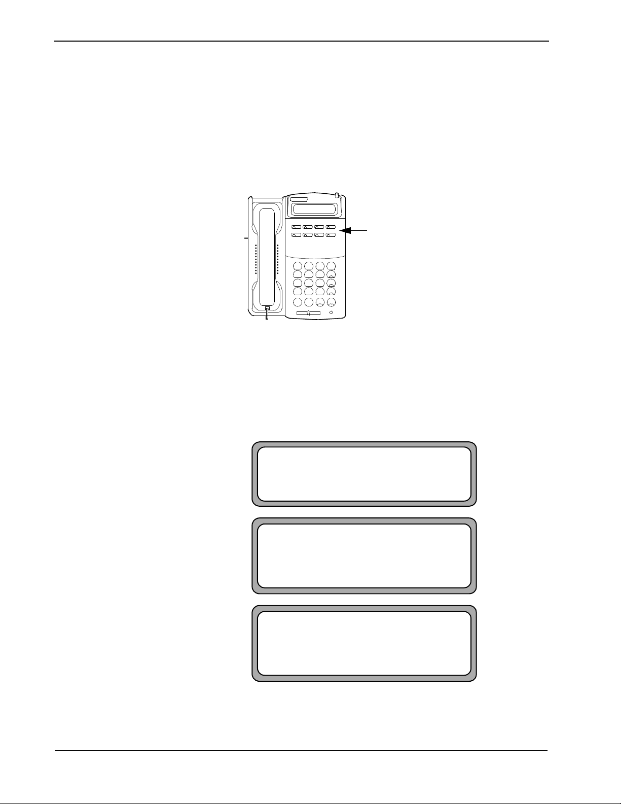
To start SPA, press the assigned
term
key at any time.
D
123
456
789
*0#
Figure 1-1 D
term
. The display has the format as spec if ied in section
term
Telephone Set
1 SMITH 3805
10:00 AM WED 30
1 (903) 555-1234
10:00 AM WED 30
1 CCIS #49234
10:00 AM WED 30
Figure 1-2 Caller ID SPA Display
Page 2 NDA-30041 Revision 5
Page 9

Second Party Alert User and Installation Guide OPERATING PROCE DURES
Brow se List of Callers
When you are using S PA, informat ion about incoming a nd outgoi ng calls di splays
on the
term
LCD. Figure 1-3 illustrates a typical
D
SPA
display:
1 SMITH 3805
10:00 AM WED 30
Figure 1-3 Example of SPA Display
In the illustrat ion abo ve, a pe rso n named Smi th is call ing on l ine 1 from ext ensio n
3805. For more information about the items shown on the LCD, see “Display
Formats” on page 7.
To browse the list of callers:
1. Make sure SPA is active. (For more information on activating SPA, see “Start
Second Party Alert” on page 2.)
You will see one of the following types of information on the
• <Line number> <Name> <Extension Number> - The line numb er of the
call followed by the caller’s name and extension, as in Figure 1-3.
term
D
display:
• Outgoing - Indicates the call is an outgoing call placed from your phone.
• Unlisted - Information for the internal caller is not available.
• Outside - Indicates tha t the incoming c all was plac ed from outside t he PBX.
(If ANI data is av ailabl e, the area cod e, pref ix, and suf f ix ar e displaye d. See
Figure 1-9 on page 8 for an example of an outside call with available ANI
data.)
• No Calls - Indicates that no calls have been received or placed.
2. To vie w information for the ne xt call o n the display, press the assigned
(6 or 8).
3. To view in formation for th e previou s call on the di splay , press the assigned
key (2 or 4).
term
D
key
term
D
NDA-30041 Revision 5 Page 3
Page 10

OPERATING PROCEDURES Second Party Alert User and Installation Guide
Signal an Internal Caller
If you are currently speaking with someone and receive an internal call, you can
use SPA to identify who is calling. You can also signal the caller to acknowledge
the call and indicate you are on another line.
1. When you receive the internal call, you can see the caller’s name and phone
extension on your telephone display.
For more information on the display, refer to “Internal Call Display Format” on
page 7.
2. To acknowledge the call and signal the caller that you are busy or on another
line, press the
The party hears a chiming sound. This sound indicates to the caller that you
acknowledge the call but cannot answer right now.
When you browse the list of callers, the parties you signaled with the chime
display with an asterisk (* ) before their names as in Figure 1-4. For more
information on how to browse a list, see “Browse List of Callers” on page 3.
term
key assigned for signaling a caller on a subline (1 or #).
D
1 * SMITH 3805
10:00 AM WED 30
Note:
Figure 1-4 Signal Internal Caller
term
The D
on the phone, information for up to five ca lls can display . If you receive more than
five calls, previous calls are overwritten on the display.
display can only show six lines of information at one time. If you are
Page 4 NDA-30041 Revision 5
Page 11

Second Party Alert User and Installation Guide OPERATING PROCE DURES
Return Call to an Internal Caller
To return an internal call:
1. Browse the list of callers to find the ca ll you want to return. For more
information on browsing calls and information displayed on the LCD, see
“Browse List of Caller s” on page 3 and “Internal Call Display Format” on page
7.
2. When information for the call you want to return is displayed, press the
key assigned for returning a call (1 or #).
3. “Calling” or one of the following messages appears:
•“Phone Busy” — Indicates that the phone you are calling is busy.
•“Bad Number” — Indicates that the number is invalid.
•“Call Failed” — Indicates that an error occurred when the call was placed.
•“DB Error” — Indicates that a database error occured.
CALLING
term
D
Figure 1-5 Placing an Internal Call
4. When you browse the list of callers after returning a call (see “Browse List of
Callers” on page 3), one of the following symbols appears before the party’s
name and number:
• ->
Displays when the number is called and no answer is received
• <-
Displays when the number is called and the party answers (internal calls
only)
NDA-30041 Revision 5 Page 5
Page 12
OPERATING PROCEDURES Second Party Alert User and Installation Guide
Return Call to an Outside Caller
To return an outside call:
1. Browse the list of callers to find the call you want to place. (See “Browse List
of Callers” on page 3 and “External Call Display Format” on page 8 for more
information.)
term
2. When information for the call you want to plac e is displayed, press t he
key
D
assigned for returning a displayed call:
• For local and metro calls, Press #.
• For long distance calls, Press 1.
3. “Calling” or one of the following messages appears.
You might also see one of the following messages:
•“Phone Busy” — Indicates that the phone you are calling is busy.
•“Bad Number” — Indicates that the number is invalid.
•“Call Failed” — Indicates that an error occurred when the call was placed.
•“DB Error” — Indicates that a database error occured.
CALLING
Quit Second Party Alert
Figure 1-6 Placing an Outside Call
4. When you browse the list of callers after returning a call, the “->” symbol
appears befo re the party’s name and number. (See “Browse List of Callers” on
page 3 for more information on browsing a list.)
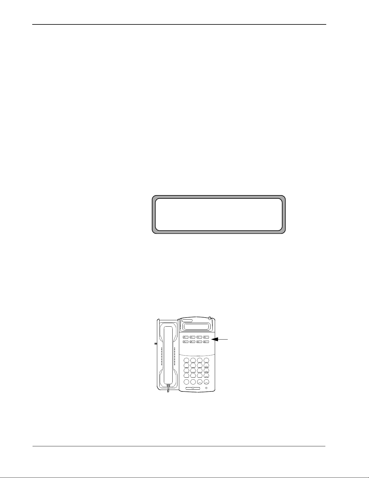
To quit using SPA, press t he
key to use, see your sys tem administ rator. The D
term
key assigned to SPA. If you are not sure which
D
term
returns to its st andard dis play.
To quit SPA, press the assigned
term
key at any time.
D
123
456
789
*0#
Dterm 8DC
Figure 1-7 D
term
Telephone Set
Page 6 NDA-30041 Revision 5
Page 13
Second Party Alert User and Installation Guide OPERATING PROCE DURES
Display Formats
Internal Call Display Format
Field
Values
Internal call information d isplayed on t he LCD is shown in the foll owing table an d
described below:
1 Character 1 Character 8 Characters 1 Character 5 Characters
Line Number Call Signal Name Blank Extension
“1” - “6”
• The line number represents the line number of an incoming call. A station can
have up to five secondary lines.
• 1 - Prime number
• 2 - first secondary line
• 3 - next secondary line
(A blank character follows the line number.)
• The call signal is a single characte r indicating what actions the user performs
on a call.
• This character is a blank if no action is performed.
• The “*” character displays when a c hime tone is issued at the caller’s station.
“”, “->”,
“<-” or “*”
OUTGOING
UNLISTED
Caller (ex: SMITH)
“ ”“0” - “ 99999”
Note:
• The “->” character displays when a number is called and no answer is
received.
Note:
• The name is an eight-character display retrieved from the name database. The
name of the caller or one of the following messages displays in this field:
•“UNLISTED” — Displays if the name is not in the database.
•“OUTGOING” — Displa ys if the call is an outgoing ca ll.
• The final field displays the caller’s extension.
Only internal PBX callers can be notified with a chime tone.
The “<-” character displays when a number is called and the party
answers. Internal PBX calls only.
1 SMITH 3805
10:00 AM WED 30
Figure 1-8 D
term
Display (Internal Call)
NDA-30041 Revision 5 Page 7
Page 14

OPERATING PROCEDURES Second Party Alert User and Installation Guide
External Call Display Format
1 Character 1 Character 1 Character 3 Characters 1 Character 3 Characters 1 Character 4 Characters
Field
Values
Line
Number
“1” - “6”“”, “->”“(““000” - “999”“)““ 000” - “999”“-““ 0000” - “9999”
External calls with Automatic Number Identification (ANI) display different
information than interna l calls . The in formation displaye d on th e LCD is sho wn in
the following table and described below:
Call Signal Parenthesis Area Code Parenthesis Extension Hyphen
• The line number represents the line number of an incoming call. A station can
have up to five secondary lines.
• 1 - Prime number
• 2 - first secondary line
• 3 - next secondary line
• The call signal is a single character indicating what actions the user performs
on a call.
• This character is a blank if no action is performed.
• The “->” character displays when a number is called.
• If an outside call ha s no ANI data, the line number and “OUTSIDE” dis play
on the D
term
.
Phone
Suffix
• The area code contains the three-digit area code of the caller.
• The phone prefix contains the three-digit phone number prefix of the caller.
• The phone suffix contains the four-digit phone number suffix of the caller.
1 (903) 555-1234
10:00 AM WED 30
Figure 1-9 D
term
Display (External Call)
Page 8 NDA-30041 Revision 5
Page 15

Second Party Alert User and Installation Guide OPERATING PROCE DURES
CCIS Call Display Format
Field
Values
CCIS calls u se Automatic Nu mber Identification (ANI) and consists of a PBX
Office Code and extension. The PBX Office Code is conf igured at the NEAX and
may contain either integer or non-integer characters. If the PBX Office Code and
extension both cont ai n int eger characters o nly, then CCIS exte nsi ons ( without the
PBX Office Code) and assoc iated us er names ca n be enter ed in the database . Calls
display using the same fo rmat as in ter nal c alls. Other CCI S call s d ispla y using the
information displayed on the LCD shown in the following table and described
below:
1 Character 1 Character 4 Characters 1 Character 9 Characters
Line
Number
“1” - “6”“”, “->” CCIS “ ” Any ASCII characters
• The line number represents the line number of an incoming call. A station can
have up to five secondary lines.
• 1 - Prime number
• 2 - first secondary line
• 3 - next secondary line
• The call signal is a single characte r indicating what actions the user performs
on a call.
• This character is a blank if no action is performed.
Call Signal CCIS Label Blank CCIS Number
• The “->” character displays when a number is called.
• The CCIS number contains the PBX office code and extension.
1 CCIS #49234
10:00 AM WED 30
Figure 1-10 D
term
Display (CCIS Call)
NDA-30041 Revision 5 Page 9
Page 16

OPERATING PROCEDURES Second Party Alert User and Installation Guide
term
Function Key Assignments
The D
are valid when Second Party Alert is enabled. SPA does not use the keys shown
with a white background.
keypad is assigned the functions found in Figure 1-11. These functions
Signal Caller/
Place Call
Previous Caller
1
GHI
4
PRS
7
*
Figure 1-11 D
ABC
2
Previous Caller
JKL
5
TUV
8
Next Caller
OPER
0
term
Keypad Layout
DEF
3
MNO
6
WXY
9
#
Next Caller
Signal Caller /
Place Call
Page 10 NDA-30041 Revision 5
Page 17

Second Party Alert User and Installation Guide INSTALLATION AND CONFIGURATION
Chapter 2 INSTALLATION AND CONFIGURATION
Installation
This guide provides specific field entries that need to be made during the
installation and con figur ation of SPA. In addit ion to this gu ide, use ins truct ions i n
the following manuals for this installati on:
• Applications Manager (APM) Installati on Manual - Contains step-by-step
instructions for installing the software from the release media.
• Applications Manag er (APM) Oper a tions Manual - Expl ains how applications
like SPA are configured in th e APM environment and how the SPA database is
created, using the entries and values provided in this chapter.
• NEAX2400 System Manuals - Give very detailed explanations about the
assignments that need to be made through the Maintenance Administration
Terminal (MAT) commands on the NEAX2400.
The installation and set up of SPA involves the following sequence of steps:
• Software Installation — SPA software must first be loaded from the release
media. Log in to the APM Pl at form Management Menu, select the Installation
of Applications/Packages option, and follow the instructions provided in the
APM Installation Manual to complete this part of the installation.
• Application Configuration — SPA is internally supported by the APM and
must be configured in the APM environment. Chapter 2, “INSTALLATION
AND CONFIGURATION” in this manual provides the information that must
be entered into this APM conf iguration f ile. Use t he instructi ons provide d in the
APM Operations Manual to make the entries contained in this section.
• Database Requirements — SPA requires a database that is constructed and
maintained through the APM Database Administration option. The process
begins with the creation of a master definition file and its related master
database. Then, an application definition file is constructed which enables the
processing of the master file into an application database. Chapter 3,
“DATABASE REQUIREMENTS” of this manual defines the information
which must be included in these definition and database files. Use the
instructions provided in the APM Operations Manual to make the entries
contained in this section.
• MAT Assignments — There are data settings that must be assigned at the
NEAX2400 Maintenance Administration Terminal (MAT) before SPA will
function. Chapter 4, “MAT ASSIGNMENTS” specifies the necess ary
commands and the values at which they are to be set. Use the in structions
provided in th e NEAX240 0 IMS Syst em Manuals to make the entries contained
in this section.
NDA-30041 Revision 5 Page 11
Page 18

INSTALLATION AND CONFIGURATION Second Party Alert User and Installation Guide
Installation (Continued)
The installation process, including its presentation in this and other manuals, is
illustrated below:
SECOND PARTY ALERT
INSTALLATION REQUIREMENTS
Discussed in: Instructions in:
Chapter 2 Software Installation
Software
APM Installation
Manual
Chapter 2 Application Configuration
Application Characteristics
Primary Parameter Configuration
OAI Facilities (Optional)
OAI Configuration Parameters (Optional)
User-Defined Parameters
Chapter 3 Database Requirements
Master Field Definitions
Master Database
SPA Application Field Formats
Process and Install SPA Database
Chapter 4 NEAX2400 IMS
Maintenance Administration Terminal (MAT)
Assignments
AIPT
(Assignment of Interface I/O Port Data in IP)
ASYD
(Assignment of System-wide Data)
ASDT
(Assignment of Station Data)
AOKC
(Assignment of OAI Key Codes)
AKYD
(Assignment of Dterm Function Key)
ASHU
(Assignment of Station Hunting-Group Data)
APM Operat ions
Manual
APM Operat ions
Manual
NEAX2400 IMS
System Manuals
Page 12 NDA-30041 Revision 5
Page 19

Second Party Alert User and Installation Guide INSTALLATION AND CONFIGURATION
The Second Party Alert Application is currently active.
Installation cannot continue until Second Party Alert has
been terminated through the Applications Manager.
Press Enter to continue. [ ]
<ENTER>
Super User (root) privileges are required.
Please enter the Super User Password:
su/root password <ENTER>
Software Installation
Installation of the Second Party Alert software is initiated from the Applications
Manager (APM) Platform Administrati on Main Menu. To display this menu, type
apmadm at the UNIX prompt and press Enter. Using instructions in the APM
Operations Manual, select the Installation of Applications/Packages option from
this menu an d load the SPA software from release media. As the installation
process executes, follow the steps described below, entering the necessary
information.
Step 1: Active Second Party Alert Application Check
In order to install the SPA software, no SPA applications can be running on the
system.
- If SPA ap plications are running, the error screen illustrated in Figure 2-1 is
displayed and installation is terminated. Use the APM to terminate all active
SPA programs before attempting another SPA installation.
Figure 2-1 Active Application Error
- If there are no active SPA programs, continue installation with “Step 2:
Superuser (Root) Password”.
Step 2: Superuser (Root) Password
- If no SPA applications are running on the system, the following password
screen displays. Use the instructions below to enter the superuser (root)
password:
Figure 2-2 Password Screen
• T ype t he correct passwor d for the root login and pr ess Enter to c ontinue. If you
enter an invalid password, the following message displays: “Invalid root
password. Do you wish to continue? (Y/N) [ ]”.
• Type y and press Enter to try again, or type n and press Enter to cancel the
installation.
NDA-30041 Revision 5 Page 13
Page 20

INSTALLATION AND CONFIGURATION Second Party Alert User and Installation Guide
Step 3: Existing SPA Installation Check
During this portion of the installation, the system determines if a previous version
of SPA is installed.
- If SP A is not installed, the installation continues with “Step 4: Existing OAI
Name Display Database Check” on page 15.
- If SPA is installed, then a warning screen is displayed, indicating that the
current installation will be saved if installation is continued. Type y and
press Enter to continue, or type n and press Enter to terminate.
Second Party Alert is currently installed on this
machine. If you choose to continue, the current
installation will be saved and all executable files
will be upgraded. Database files will not be altered
since this version uses the same database formats as
previous versions.
Do you wish to continue? (y/n) [y]
Figure 2-3 Previous Version Detected
<ENTER>
- If you chose to cont inue th e install ation af ter a pre vio us ver sion of SPA was
detected, the following screen will be dis p l aye d. Type y and press Enter to
delete this previously saved installation, or type n and press Enter to
terminate.
A copy of "/oai/app/party.old" already exists on your system.
This copy must be removed before the current system can be
saved. If it is not removed, installation will be aborted.
Do you wish to remove "/oai/app/party.old"? (y/n) [y]
<ENTER>
Figure 2-4 Delete Previous Version
- If you chose to sav e the pre vious versi on, the follo wing message is displ ayed
after the existing SPA installation has been saved. Press Enter to continue
with “Step 4: Existing OAI Name Display Database Check” on page 15.
The current installation of Second Party Alert is now
saved in "/oai/app/party.old".
Press Enter to continue. [ ]
<ENTER>
Figure 2-5 Saved Previous Version Confirmation Message
Page 14 NDA-30041 Revision 5
Page 21

Second Party Alert User and Installation Guide INSTALLATION AND CONFIGURATION
An OAI Name Display Database exists on this system. You may
use this database with Second Party Alert, or create a separate
Names Database.
Do you wish to use the existing OAI Name Display Database? (y/n) [y]
<ENTER>
Please enter the MSF Op-code number (128...191) that will be
used by Second Party Alert.
MSF Op-code: [
128] <ENTER>
You entered [128] -- is this correct? (y/n) [y]
<ENTER>
Step 4: Existing OAI Name Display Database Check
In this step , the system determines if an OAI Name Display Database is installed
on the system:
- If the Name Display Database is not installed, the MSF Op-code scr een is
displayed as described in “Step 5: Specify the MSF Op-code Number”.
- If the Name Display Databas e is installed, th e followi ng screen is display ed.
Type y and press Enter to use the OAI Name Display Database, or type n
and press Enter to create a separate Names Database.
Figure 2-6 Database Exists
Step 5: Specify the MSF Op-code Number
Use the following instructions to specify the MSF Op-code Number:
• Type the MSF Op-code used by SPA and press Enter.
- If you enter an invalid MSF Op-code, the message “ERROR: Invalid MSF
number , please enter a v alue of 128... 191!!!” is disp layed. Press Enter, type
a valid MSF Op-code, and press Enter again. When you enter a valid MSF
Op-code, that code is displayed on the screen.
Figure 2-7 Verify MSF Op-code
• Type n and press Enter to cancel the entry and try again, or type y and press
Enter to accept the entry and continue.
NDA-30041 Revision 5 Page 15
Page 22

INSTALLATION AND CONFIGURATION Second Party Alert User and Installation Guide
Step 6: Specif y the OAI Key Code
Use the following instructions to specify the appropriate OAI Key Code:
• Type the OAI Key Code used by the PBX to generate the MSF Op-code
specified in “Step 5: Specify the MSF Op-code Numbe r” on page 15, and pr ess
Enter.
- If you enter an invalid OAI Key Code, the message “ERROR: Invalid OAI
Key Code , please e nter a v al ue of 1...14 !!!” is displayed. Type Enter, t ype a
valid OAI Key Code, and press Enter again. When you enter a valid OAI
Key Code, that code is displayed on the screen.
Please enter the OAI Key Code (1...14) used by the PBX to
generate MSF Op-code 128.
OAI Key Code: [1 ] <ENTER>
You entered [1] -- is this correct? (y/n) [y] <ENTER>
Figure 2-8 Confirm OAI Key Code
• Type n and press Enter to cancel the entry and try again, or type y and press
Enter to accept the entry and continue.
Step 7: Specif y the Chime Tone
Use the following instructions to specify the chime tone used to alert internal
callers:
• Type the Chime Tone used by SPA to alert internal calle rs and press Enter.
- If you enter an invalid Chime Tone, the message “ERROR: Invalid Chime
T one Number , please enter a valu e of 0...7!!!” is displayed. Press Enter, type
a valid Chime Tone, and press Enter again. When you enter a valid Chime
Tone, the chime tone number is displayed on the screen.
Please select the Chime Tone used to alert internal callers
from one of the following:
0 Connected Tone
1 Release Tone
2 Request Tone
3 Warning Tone
4 Special Tone
5 Acknowledgment Tone
6 Non-acknowledgment Tone
7 Confirmation Tone
Chime Tone Number: [0] <ENTER>
You entered [0] -- is this correct (y/n) [y] <ENTER>
Figure 2-9 Verify Chime Tone
• Type n and press Enter to cancel the entry and try again, or type y and press
Enter to accept the entry and continue.
Page 16 NDA-30041 Revision 5
Page 23

Second Party Alert User and Installation Guide INSTALLATION AND CONFIGURATION
Do you want each station to chime when a call
is received on a secondary line (y/n) [y] <ENTER>
You entered [y] -- is this correct (y/n) [y] <ENTER>
Please enter your local area code: [972] <ENTER>
You entered [972] -- is this correct (y/n) [y] <ENTER>
Please enter you NEAX trunk access prefix: [9] <ENTER>
You entered [9] -- is this correct (y/n) [y] <ENTER>
Step 8: Specify the Secondary Line Chime Flag
Use the following instructions to set the Secondary Line Chime flag:
• Type y and press Enter to enable the Secondary Line Chime, or type n and press
Enter to disable it. The flag you selected is displayed on the screen.
Figure 2-10 Secondary Line Chime Flag
• Type n and press Enter to cancel the entry and try again, or type y and press
Enter to accept the entry and continue.
Step 9: Specify the Local Area Code
Use the following instructions to enter the local area c ode:
• Type the local area code and press Enter. The area code you entered displays
on the screen.
Figure 2-11 Local Area Code
• Type n and press Enter to cancel the entry and try again, or type y and press
Enter to accept the entry and continue.
Step 10: Specify the NEAX Trunk Access Prefix
Use the following instructions to enter the NEAX Trunk Access Prefix:
• Type the NEAX Trunk Access Prefix and press Enter. The prefix you entered
displays on the screen.
Figure 2-12 Verify Trunk Access Prefix
• Type n and press Enter to cancel the entry and tr y ag ai n, or y and press Enter
to accept the entry and continue.
NDA-30041 Revision 5 Page 17
Page 24

INSTALLATION AND CONFIGURATION Second Party Alert User and Installation Guide
Step 11: Specify the Local Call Method
Use the following instructions to specify the method used to place local calls:
• Type the number that specifies the correct local call method for your area, and
press Enter.
- If an invalid value is entered, the message “ERROR: Inv alid Loc al Met hod,
please enter a value of 1...2! !!” is di splayed. Pr ess Enter, type a va lid v alue ,
and press Enter again.
- When a valid value is entered, the following will be displayed.
Please select the method used to place local calls
from one of the following:
1 7 Digits Only (555 1234)
2 Area Code + 7 Digits (987 555 1234)
Local Call Method: [1] <Enter>
You entered [1] -- is this correct (y/n) [y] <Enter>
Figure 2-13 Local Call Method
• Type n and press Enter to cancel the entry and tr y ag ai n, or y and press Enter
to accept the entry and continue.
Page 18 NDA-30041 Revision 5
Page 25

Second Party Alert User and Installation Guide INSTALLATION AND CONFIGURATION
The default Second Party Alert Application Configuration
will now be installed by the autoconfig program. After the
Second Party Alert Installation has concluded, be sure to
check the configuration using the Applications Manager (APM)
and modify any settings that are different on your system.
Press Enter to continue [ ] <ENTER>
Second Party Alert Auto-Configuration
/oai/utils/autocfg running...
/oai/utils/autocfg: 2nd_Party_Alert application configured.
/oai/utils/autocfg terminated normally.
Second Party Alert Auto Configuration Complete
Press Enter to continue [ ] <ENTER>
Step 12: SPA Auto-Config — New Configuration
- If a previous version of SP A is installed on the system, installation continues
with “Step 13: SPA Auto-Config — Update Existing Configuration” on
page 20.
- If SPA is not
installed, the following information screen is displayed,
indicating that the default configuration values will be used for auto
configuration.
Figure 2-14 SPA Auto-Config (New Config)
• Type Enter to begin the auto configuration process. During the SPA auto
configuration, the following screen is displayed:
Figure 2-15 SPA Auto-Config Complete (New Config)
• When the auto configuration has completed, type Enter and continue with
“Step 14: Database Template Installation” on page 21.
NDA-30041 Revision 5 Page 19
Page 26

INSTALLATION AND CONFIGURATION Second Party Alert User and Installation Guide
Step 13: SPA Auto-Config — Update Existing Configuration
- If a previous version of SPA is installed on the system, then the following
information screen is displayed, indicating that the current configuration
will be updated.
The current Second Party Alert Application Configuration will
be modified to support the new version. When the autoconfig
program is executed by the installation program, you will be
informed that "2nd_Party_Alert" is already configured.
When the autoconfig program asks if you want to reconfigure, be
sure to answer with ’Y’ or ’y’ to ensure that the modified Second
Party Alert Configuration is installed.
After the Second Party Alert Installation has concluded, be sure
to check the configuration using the Applications Manager (APM)
and validate that all settings are correct for you system.
Press Enter to continue [ ] <ENTER>
Figure 2-16 SPA Auto-Config (Existing Config)
• Type Enter to begin the auto configuration process. During the SPA auto
configuration the following screen is displayed:
Second Party Alert Auto-Configuration
/oai/utils/autocfg running...
/oai/utils/autocfg: 2nd_Party_Alert is already configured.
/oai/utils/autocfg: Reconfigure (y/n)? y <ENTER>
/oai/utils/autocfg: 2nd_Party_Alert application configured.
/oai/utils/autocfg terminated normally.
Second Party Alert Auto Configuration Complete
Press Enter to continue [ ] <ENTER>
Figure 2-17 SPA Auto-Config Complete (Existing Config)
• At the “Reconfigure (y/n)?” prompt, type y and press Enter to update the
existing SPA configuration. When the auto configuration has completed, press
Enter to continue with “Step 14: Database Template Installation”.
Page 20 NDA-30041 Revision 5
Page 27

Second Party Alert User and Installation Guide INSTALLATION AND CONFIGURATION
Second Party Alert Database Template Installation
Copying Second Party Alert Names Master Database template
Copying Second Party Alert Names Application Database template
Copying Phone Line Master Database template
Copying Phone Line Application Database template
Copying Tenant Master Database template
Copying Tenant Application Database template
Press Enter to continue [ ] <ENTER>
Second Party Alert Installation Complete
Step 14: Database Template Installation
• After auto conf iguration, t he installation script will inst all the database template
files. The following screen will be displayed:
Figure 2-18 Database Template Installation
• After the database templates have been installed, SPA installation is complete.
Now go to “Configure Application” on page 23 to configure the SPA
applications.
NDA-30041 Revision 5 Page 21
Page 28

INSTALLATION AND CONFIGURATION Second Party Alert User and Installation Guide
Configuration
The following sections describe the configuration of Second Party Alert (SPA).
Access System Administration Menu
Change Facility Number
To access the System Administration Menu:
• Select the APM option from the APM Platform Management menu.
• Enter the System Administrator password at the APM password screen.
The Number of Facilities must be set to 9 or greater in the OAI Li brary
Configuration before SPA 1.5 (or previ ous ver sions ) will work. (T he defa ult i s 8.)
Using the APM, perform th e following steps t o change the defaul t value of Number
of Faciliti es:
• Select System Configuration from the System Administration menu.
• Select OAI Library Configuration.
• Select Modify.
• Press the Enter key.
• Use the arrow keys to move to the Number of Facilities field.
• Enter 9 (or greater) and press the Enter key .
• Select the Quit option two times to return to the System Administration menu.
Page 22 NDA-30041 Revision 5
Page 29

Second Party Alert User and Installation Guide INSTALLATION AND CONFIGURATION
Configure Application
SPA is configured into th e APM system using the Add funct ion of t he Applic ation
Configuration option on the APM System Administration menu. Enter the
Application Configuration option from the System Administration menu.
This section contains the information that you should enter into the configuration
file for SPA. For specific instructions on what these parameters mean and how to
make these entries, use the APM Operations Manual.
Step 1: Application Characteristics
When adding SPA to the APM Application Configura tion fi le, defi ne it as follows :
Note:
This step is done automatically during installation if you answer
autoconfig prompt.
Parameter Default Entry Description
OAI Application Y Indicates whether or not (Yes or
No) SPA communicates with the
NEAX2400 using OAI processes.
CRT Application N Indicates whether or not (Yes or
No) SPA requires a terminal screen
that is of the same type as the one
used by the APM
YES
to the
Communication Queue N Indicates whether or not (Yes or
No) this non-OAI application
needs an IPC queue to
communicate with other pr oce ss es.
NDA-30041 Revision 5 Page 23
Page 30

INSTALLATION AND CONFIGURATION Second Party Alert User and Installation Guide
Step 2: Primary Configuration Parameters
On the APM Configuration Entry screen, make an entry for each SPA parameter
shown below. If the para meter is followed b y an asterisks (* ) in the table , you must
make the entry exactly as shown. Other entries serve only as examples — actual
entries are site-dependent.
Note:
Parameter Default Entry Description
This step is done automatically during installation if you answer
autoconfig prompt.
YES
to the
Application Name 2nd_Party_Aler t Specifies the name to be di splayed
in the APM menus. This name is
displayed however it is entered
here (i.e., capital letters, lower
case, etc.)
Executable Filename* /oai/app/party/bin/spa Indicates the path name of the
executab le file.
Group* (no entry) Indicates the group to whi ch SP A is
associated.
Response Mode* I Indicates the a ction that the APM i s
to take with SPA should a member
of the group terminate, such as
I(gnore).
Initialization Batch N Indicates whether or not (Yes or
No) SPA is to be initialized
automatically when the OAI
system is initialized.
T erminati on Mode* M Indicates ho w the APM is to notify
SPA to terminate (e.g., message).
Standard Output /dev/null Designates the f i le int o which SPA
output is redirected.
Number of Restarts 0 Indicates ho w many times the APM
may restart SPA after it terminates
erroneously.
Page 24 NDA-30041 Revision 5
Page 31

Second Party Alert User and Installation Guide INSTALLATION AND CONFIGURATION
Step 3: OAI Facilities
According to instru ctions in the APM Operations Manua l, designate the f ollowing
NEAX2400 facilities for SPA using the Faci lities command on the Configura tion
Entry screen. These facilities are automatically set up when you run aut oconfig
during installation.
MRFI Mode Release (I) MRFR Mode Release (R)
MSF OAI Mode Set NTF Number Transfer
SMFR Status Request (R) SMFN Status Noti fication (N)
TCFD Terminal Control (D) TCFI Terminal Control (I)
SCF Switch Control
Note:
The same MSF Op-Code that is specified here must be assigned to SPA at the
NEAX MAT. F or more infor mation, see Chapter 4, “MAT ASSIGNMENTS”. Only
one MSF can be specified or the application terminates immediately.
NDA-30041 Revision 5 Page 25
Page 32

INSTALLATION AND CONFIGURATION Second Party Alert User and Installation Guide
Step 4: Secondary OAI Configuration Parameters
Using the OAI-Conf command on the APM Configuration Entry screen, make an
for each of the following parameters. If the parameter is followed by an asterisks
(*) in the table, y ou must make the ent ry exactly as s hown. Other entries serve only
as examples — actual entries are s ite-dep endent. Use th e inst ructions provided fo r
this option in the APM Operations Manual. These parameters are automatically set
up when you run autoconfig during installation.
Parameter Default Entry Description
Database Name #1* /oai/db/cur/nmdsp Indicates the path name of the
database containing the names and
extensions of everyone in the
organization.
Note:
This entry refers either to the
name of the SPA database
created through the APM (see
Chapter 3, “DATABASE
REQUIREMENTS”) or to the
Name Display database t hat is
to be used by SPA. If the Name
Display database is to be used,
enter its name here.
Database Name #2* /oai/db/cur/phonline Indicates the path name of the
database containing primary
extensions and the secondary
(virtual) lines associated to them.
Timeout Value #1 60 Designates the number of seconds
that SPA waits before clearing
information from the D
term
LCD
panel.
Timeout Value #2 0 Indicates that there is not a timeout
period for the second timeout value.
Tenant Number 1 Specifies the number of the tenant
that SPA serves.
Source Link Name OAI1TCP Identifies the port on the sou rce side
of the communication link.
Destination Link Name PBX1TCP Identifies the port on the destination
side of the communication link.
Association Recovery 30 Designates the number of seconds
SPA waits before trying to
re-establish an association with the
NEAX that has been released.
Page 26 NDA-30041 Revision 5
Page 33

Second Party Alert User and Installation Guide INSTALLATION AND CONFIGURATION
Step 5: User-Defined Parameters
Make the following addi tional paramet er entry through t he UserDefined co mmand
on the OAI Configurati on screen. The se paramete rs are aut omaticall y set up when
you run autoconfig during installation.
Parameter Typical Entry Description
User Defined #1 7 The OAI key code assigned on the
MAT via the AOKC command.
User Defined #2 2 This is the chime tone value
(assigned at installation) that is
heard by the cal ler and called party.
The tones are:
• 0Connected tone*
• 1Release tone
• 2Request tone
• 3Warning tone*
• 4Special tone*
• 5Acknowledgment tone
• 6Non-acknowledgment tone
• 7Confirmation tone
Note:
For 4200 V6 or earlier
version of the PBX softwar e,
the connect tone, warning
tone, and special tone
produce
any audio tones.
do not
User Defined #3 (no entry) This allows the station to chime
when a call is received on a
secondary line. If the value is set to
, a chime sounds. If it is set to N,
Y
no chime sounds. the default is N.
User Defined #4 8 This value des cribes th e size of the
display name used by the name
display database def ined in Second
Party Alert. Valid values for this
field are 8 and 16. The default is 8.
User Defined #5 Enter the local area code in this
field (assigne d at installat ion).
User Defined #6 Enter the NEAX trunk access
prefix (assigned at installation).
User Defined #7 /oai/db/cur/tenants Indicates the path name of the
tenant number database.
NDA-30041 Revision 5 Page 27
Page 34

INSTALLATION AND CONFIGURATION Second Party Alert User and Installation Guide
Step 5: User-Defined Parameters (Cont)
Parameter Typical Entry Description
User Defined #8 7 This field specifies the number of
digits used to place a local call.
Valid values for this field are 7 (7
digit phone number only) and 10
(area code + 7 digit p hone number).
If this field is blank or an invalid
value is specified, the default value
of 7 is used by the program.
User Defined #14 /T L1 U9 D/oai/log/dbg/pa rty .out This is not part of the d efault setup.
Enter the value listed to enable
debug logging.
Caution:
This file gr ow s very qu ickly .
Please monitor the file size
to ensure the har d drive does
not run out of space.
This completes the confi guration of SP A in the APM. Now go to Chapter 3,
“DATABASE REQUIREMENTS” to create its database support.
Page 28 NDA-30041 Revision 5
Page 35

Second Party Alert User and Installation Guide DATABASE REQUIREMENTS
Chapter 3 DATABASE REQUIREMENTS
This chapter assumes that SPA is not going to use the OAI Name Display
application database and must have one built. In this case, SPA requires two
databases that are created throu gh the Database Admi nistration opt ion on the APM
System Administration Menu.
Database creation in the APM involves the following 4-step process:
Step 1
- Create
Master Definition File
Instructions
Step 2
- Build
Master Database File
Step 3
- Specify
Application Formats
Step 4
- Process
Application Database
• Step 1 - Create a Maste r Definition File: This step involves creating the
master definition file that defines the fields in the master database file.
• Step 2 - Build a Master Database File: This step involves entering data (e.g.,
actual phone lines) into the maste r dat aba se fields that were just defined in the
master definition file in Step 1.
• Step 3 - Cr eate an A pplication Def initio n File: I n this step, a de fi nition f i le is
created for the SPA database. This file defines the formats by which data from
the master file is to be converted to meet the needs of SPA.
• Step 4 - Process and Install the Application Database: In this step, the
Process and Install Application Databases options on the APM Database
Administration menu crea tes the file that will be used by SPA. When the
Process option is activated, data is drawn from the master database and
converted to the formats specified in the application definition file. The Install
option is then activated to enable SPA to copy its database.
The information required for the SPA database is provided in the ta ble on the
following page. Using this information with the procedural instructions provided
in the APM Operations Manual, enter the Database Administration option on the
APM System Administration Menu and build the SPA database. Any messages
displayed during these steps are addressed in the Process and Error Messages
chapter of t he APM Operations Manual.
Note:
NDA-30041 Revision 5 Page 29
Remember to complete Step 4, Process and Install the Application Database, for
each database after you enter the following information.
Page 36

DATABASE REQUIREMENTS Second Party Alert User and Installation Guide
Name Display Database Information
Field Description
The Name Display databas e field entries are shown in the following table and
defined below the table. N ame the Master Definition File name_m and the
Application Definition File nmdsp.
Note 1:
Note 2:
Type Size
You do not have to create this database if the Name Display application is
installed, and its database is going to be used.
Name the
the Build Master Dat aba se o pt i on on t he Dat ab as e A dmi ni stration menu. Name
the
Master Definition File
name_m
nmdsp
file in the Specify Application Database Fields option.
Min.
Value
file in the Define Master Database Fields option, chosen from
Application
Definition File
Max.
Value
Data Type Typical Entry
Extension N 5 0 99999 ASCII 4290
Display Name A 8 ASCII F. Smith
Field Definitions
• Extension - The five-digit primary extens ion number. This is the
number that is displayed with the caller’s name when this
phone is used to place the call.
• Display Name - The name that is to be displayed on the D
The name must be entered in the format, F.Lucas, with the
first name init ial separated from the last name by either a
period (.) or a blank space.
Master Database
term
LCD panel.
Page 30 NDA-30041 Revision 5
Page 37

Second Party Alert User and Installation Guide DATABASE REQUIREMENTS
Phone Line Database Information
Field Description
The Phone Line database field entries are shown below in the table and defined
below the table. Name the Master Definition File phone_m and the Application
Definition File phonline.
Note:
Type Size
Name the
from the Build Master Database option on the Database Administration menu.
Name the
Master Definition File
phone_m
phonline
Min.
Value
file in the Define Master Database Fields option, chosen
file in the Specify Application Database Fields option.
Application
Definition File
Max.
Value
Data Type Typical Entry
Phone Line 1 N 5 0 99999 Long Integer 4290
Phone Line 2 N 5 0 99999 Long Integer 4291
Phone Line 3 N 5 0 99999 Long Integer 4292
Phone Line 4 N 5 0 99999 Long Integer 4293
Phone Line 5 N 5 0 99999 Long Integer 4294
Phone Line 6 N 5 0 99999 Long Integer 4295
Field Definitions
Master Database
• Phone Line 1 - The five-digit primary extension number. This is the
number that is displayed with the caller’s na me when this
phone is used to place the call.
• Phone Line 2 - 6 - The five-digit secondary, or virtual, lines that are
associated with the primar y e xte nsion t hat w as ente red in
the first field. These virt ual lines must be a ssi gne d t o this
primary line and to a hunt group through the NEAX
Maintenance Administration Terminal (see MAT
Assignments).
NDA-30041 Revision 5 Page 31
Page 38

DATABASE REQUIREMENTS Second Party Alert User and Installation Guide
Tenant Number Database Information
Field Description
First Extension ASCII 10 ASCII 1000
Last Extension ASCII 10 ASCII 1099
The Tenant Number databas e field entries are shown below in the table and defi ned
below the table. The database contains a list of extensions and associated tenant
numbers used by the PBX. A tenant number can be associated with an individual
numeric extension or a range of numeric extensions. A given tenant number can
have more than one record if all of the extensions associated with it are not
consecutive. Tenant nu mbers can also be associated wit h individual extensions th at
contain non-numeri c charac ters such as ‘*’ or ‘#’. Make the Master Definition File
tenant_m and the Application Definition File tenants.
Note:
Name the
from the Build Master Database option on the Database Administration menu.
Name the
Type Size Min.
tenant_m
tenant
Master Definition File
file in the Define Master Database Fields option, chosen
file in the Specify Application Database Fields option.
Value
Max.
Value
Application
Definition
File
Master Database
Data Type Typical Entry
Tenant Number Numeric 3 1 255 Short Integer 1
Field Definitions
• First Extension- the first extens ion in the range of extensions.
• Last Extension- the last extension in the range of extensions.
• Tenant Number- this field contains the asso ciated tenant number.
This completes creation of SPA database support . Now go to Chapter 4, “MAT
ASSIGNMENTS” to make the necessary command assignments at th e NEAX2400
MAT.
Page 32 NDA-30041 Revision 5
Page 39

Second Party Alert User and Installation Guide MAT ASSIGNMENTS
Chapter 4 MAT ASSIGNMENTS
This guide assumes that data settings that affect the operation of all OAI software
on a system-wide basis have already been assigned on the NEAX Maintenance
Administration Terminal (MAT). Such settings include system index values and
assignment of Interface I/O Port Data in the Interface Processor (IP). For more
information about these system data settings and the MAT commands described
below for SPA, refer to the OAI Module Installation Manual for the NEAX2400
IMS, the NEAX2400 IMS Command Manual, the NEAX2400 IMS Job Specifica tion
Manual, and the NEAX2400 IMS Programming Manual.
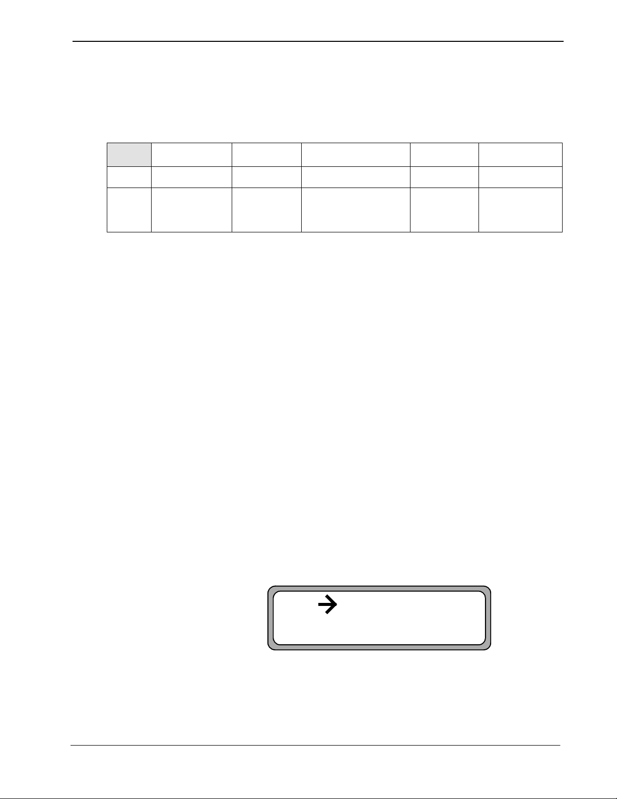
The user-defined parameter #1 assigned during the application configuration on
page 27 identifies the function key that the phone user presses to display call
information. You must now assign this key at the MAT to the Mode Set Facility
(MSF) for al l D
Using the AOKC command, assign t he MSF fa cility and its Op-C ode to one of the
14 OAI Key Codes in the MAT. Each of these OAI Key Codes corresponds to an
AKYD Function Key Index (FKI) value that is then assigned to the specific D
function key. This process is illustrated below.
terms
that will be able to display calling party information.
term
APM
Application
Configuration
Designatio n of
and its Op-
(Type)
for Use by
Code
Application
Facility
PBX Correspondence of
AOKC AKYD
OAI Function
MAT
AOKC
Command
Assignment of
Key Code
and 14)
Facility Type and Op-
an OAI
(between 1
to the Same
Code
Key Codes
1 < . . . .> 34
2 < . . . .> 35
3 < . . . .> 36
4 < . . . .> 37
5 < . . . .> 38
6 < . . . .> 39
7 < . . . .> 40
8 < . . . .> 41
9 < . . . .> 42
10 < . . . .> 43
11 < . . . .> 44
12 < . . . .> 45
13 < . . . .> 46
14 < . . . .> 47
Key Indices
MAT
AKYD
Command
Assignment of
Corresponding MAT
Function Ke y Inde x to
specific D
a
Function Key
Figure 4-1 OAI Function Key Assignment
A knowledge of the D
term
stations in the NEAX system and which ones will be set
up to access SPA is necessary for using the following commands.
term
. . . . .
. . . . .
. . .
. . .
NDA-30041 Revision 5 Page 33
Page 40

MAT ASSIGNMENTS Second Party Alert User and Installation Guide
AIPT Command: (Ass ignment of Interface I/ O Port Data in IP )
This command can be used to a ssign TCP/IP address of the system’s IP. Let system
and UAP both in ethernet.
• IP-NO: Assign face Processor Number.
• Port Number
• PNI: Assign 1
• KIND: Assign 3 for choose TCP/IP protocol.
• Assign ETHER-PKGNO
• Assign TCP/IP address
ASYD Command: Assignment of System Data
If the Name Display appli catio n is not insta lled a nd a Name Displa y Databas e has
been created through the APM for SPA use, the Name Display feature on the
NEAX2400 does not need to be enabled, and this MAT as si gnment does not have
to be made. If the Name Display application is installed and its database is going
to be used by SPA, the Name Displ ay fe ature on the NEAX2400 mus t be e nabled .
This feature allows SPA to access the Name Displa y database and retrieve th e
name associated wit h the calling extens ion. Use the ASYD command to enabl e this
feature if necessary:
• System 1, Index 78, bit 3
Enter either of the following two value s:
• 0: Display name only.
• 1: Display calling/called number with name.
• System 1, Index 78, bit 5
Enter 1 (yes) to set name display feature in to service.
ASDT Command: Assignment of Station Data
Each D
a manner that is supportive of the SPA function. In addition to its pri mary incoming
line, each supported D
assigned to it, and those primary/virtual lines assigned into a pilot hunt group.
Then, when the D
the next virtual line in that hunt group. Use the ASDT and ASHU commands to
complete t hese assignments for each supported D
1. Enter the same tenant number that is configured for the application in the APM
2. Identify virtual lines for e ach supported D
term
that is to carr y SPA must be set up to ha ndle mul tipl e inco ming calls in
term
must have a user-defined number of virtual lines
term
user is on the primary line, any incoming call is wrapped to
Application Configuration option (Tenant #1, page 26).
secondary, or virtual, lines entered for each D
term
:
term
. These lines should agree with the
term
station in the database.
Page 34 NDA-30041 Revision 5
Page 41

Second Party Alert User and Installation Guide MAT ASSIGNMENTS
AOKC Command: (Assignment of OAI Key Codes)
This comma nd is used to associate the MSF facility and its Op-Code that was
configured in the APM for the application to one of the OAI Key Codes in the
MAT.
1. Select an unused OAI Key Code, from 1 to 14. To determine what Key Codes
are available for assignment, use the LOKC command to list the AOKC Key
Codes that are already assigned.
2. Enter the type of facility using the value that designates the MSF.
3. Enter the same MSF Op-Code that was configured fo r SPA in the APM. Retrieve it using the Providers command on the APM Conf iguration Entry scr een.
AKYD Command: (Assignment of D
The AKYD command can only be used to assign key data on t hose D
already been assigned through the ASDT command.
MAT Function Key Indexes #34 to #47 have been designated for use in the OAI
system and correspond to the 14 OAI Key Codes as illustrated in Figure 4-1 on
page 33. The AKYD command is used to assign a D
MAT Function Key Index that , in turn, corresponds to the previously assigned OAI
Key Code. This command must be used to assign the function key on each D
that is to be set up with access to SPA.
term
1. D
2. Enter the same tenant number that is configured for the application in the APM
3. Enter the station number of the D
4. Enter the D
5. Assign the virtual line, such as the subline.
function ke y #8 was de signated in t he applicat ion conf iguration as the ke y
that is to be pressed to activate SPA from the D
rameters on page 27).
Application Configuration option (Tenant #1, page 26.)
signed.
term
function key to the MAT Function Key Index that in turn corre-
sponds to the previously assigned OAI Key Code.
term
Function Key)
term
on which the function key is being as-
terms
that have
term
function key to the speci fic
term
(Step 5: User-Defined Pa-
term
NDA-30041 Revision 5 Page 35
Page 42

MAT ASSIGNMENTS Second Party Alert User and Installation Guide
PBX Correspondence of
AOKC AKYD
OAI Function
Key Indices
MAT
AKYD
Command
Function Key
Index #43
assigned to
term
D
Function
Key #9
. . . . .
. . . . .
. . .
. . .
APM
Application
Configuration
Directory Dialer
confi gured for
MSF #129
MAT
AOKC
Command
OAI Key
Code #10 given
MSF facility type
and
Op-Code #129
Key Codes
1 < . . . .> 34
2 < . . . .> 35
3 < . . . .> 36
4 < . . . .> 37
5 < . . . .> 38
6 < . . . .> 39
7 < . . . .> 40
8 < . . . .> 41
9 < . . . .> 42
10 < . . . .> 43
11 < . . . .> 44
12 < . . . .> 45
13 < . . . .> 46
14 < . . . .> 47
Figure 4-2 OAI Function Key Assignment
In the example above, MSF was selected in the APM Application Configuration,
and its Op-Code was determined to be #129. MSF #129 is then assigned through
the AOKC command to an OAI Key Code. In this example the Key Code is #10.
term
The D
function key that is to be used to access SPA is configured as function
key #8. Since OAI Key Code #10 corresponds in the PBX to MAT Function Key
Index #43, D
term
function key #8 is assigned to Function Key Index #43 using the
AKYD command. Now whenever a phone user presses function key #8 on any
assigned Dterm, MSF 129 initiate s communication with SPA for disp lay of calling
party information
ASHU Command: Assignment of Station Hunting-Group Data
1. Enter the same tenant number that is configured for the application in the APM
Application Configuration option (Tenant #1, page 26).
2. For each primary station number, enter the virtual line numbers that are to be in
the hunt group. These virtual line numbers must agree with those assigned in
the ASDT command and those entered in the database.
SPA is now installed and ready to be initialized. Enter the APM Operations Menu
and initialize SPA through the Non-CRT Application option, according to
instructions provided in the APM Operations Manual.
Page 36 NDA-30041 Revision 5
 Loading...