


2000
Table of contents
 Loading...
When Space is at a Premium and Flexibility is Key
P OWERMATE®2000 SERIES
USER’S GUIDE

Proprietary Not ice and Liability Disclai mer
The information disclosed in this document, including all designs and related
materials, is the valuable property of NEC Computers Inc. (hereinafter “NECC”)
and/or its licensors. NECC and/or its licensors, as appropriate, reserve all patent,
copyright and other proprietary rights to this document, including all design,
manu fact urin g, repr odu cti on, u se, and sa l es right s th er et o, excep t to the ex t ent sai d
righ ts are expr es sly grant ed to ot hers.
The NE CC product ( s ) discussed in this docu ment are warranted in accor dance with
the ter m s of the War ran ty Sta t emen t a ccomp an yin g ea ch pr odu ct. However , a ctua l
performance of each such product is dependent upon factors such as system
configuration, customer data, and operator control. Since implementation by
customers of each product may vary, the suitability of specific product
configurations and applications must be determined by the customer and is not
warranted by NECC.
To allow for design and specification improvements, the information in this
document is subject to change at any time, without notice. Reproduction
of this document or portions thereof without prior written approval of
NECC is prohibited.
NEC is a registered trademark of NEC Corporation.
PowerMate an d MultiSync are registered trademarks and VistaS can is a trademark of NEC
Corporation or one of its subsidiaries. All are used under license by NEC Corporation
and /or one or m ore of its sub sidiaries .
All other trademarks and registered trademarks are the property of their respective
trademar k ow ners .
First Printing — May 2000
Copyright 2000
NEC Computers Inc.
15 Business Park Way
Sacramento, CA 95828
All Rights Reserved

Contents
Using This Guide
Text Conventions.................................................................................... viii
Related Documents................................................................................... ix
1 Reviewing System Features
Front Features ......................................................................................... 1-2
System Controls and Lamps ............................................................ 1-4
LCD Panel...................................................................................... 1-5
Diskette Drive................................................................................. 1-5
Hard Drive......................................................................................1-6
CD-ROM Drive.............................................................................. 1-6
Speakers......................................................................................... 1-6
Left Side Features ................................................................................... 1-6
Audio Connectors........................................................................... 1-7
Volume Control.............................................................................. 1-8
PC Card Slots.................................................................................1-8
Fan................................................................................................. 1-8
Rear Features.......................................................................................... 1-8
Universal Serial Bus Ports............................................................... 1-9
DC Power Connector...................................................................... 1-9
PS/2 Mouse Port ........................................................................... 1-10
PS/2 Keyboard Port ...................................................................... 1-10
VGA Monitor Connector .............................................................. 1-10
Printer Port ................................................................................... 1-10
Serial Port..................................................................................... 1-10
LAN Connector............................................................................ 1-11
Bottom Features.................................................................................... 1-11
Memory Sockets........................................................................... 1-12
Password Clear Jumper................................................................. 1-12
Microdesktop Chassis........................................................................... 1-12
System Overview.................................................................................. 1-13
Hardware...................................................................................... 1-13
Software....................................................................................... 1-14
Preloaded Microsoft Operating System ................................. 1-14
NEC OS Restore CD ............................................................ 1-14
NEC Application and Driver CD........................................... 1-14
Security........................................................................................ 1-15
Content s iii

2 Setting Up the System
Cable Connections...................................................................................2-2
Startup.....................................................................................................2-2
Shutdown................................................................................................2-3
Power-Saving Operation..........................................................................2-4
System Care ............................................................................................2-5
Protecting Your System From Damage............................................2-5
Keeping Your System in Good Condition ........................................2-6
Moving or Shipping Your System....................................................2-7
More Information ....................................................................................2-8
3 Configuring the System
Configuration Tools and Utilities.............................................................3-2
BIOS Setup Utility...................................................................................3-4
How to Start Setup...........................................................................3-4
How to Use Setup............................................................................3-5
Main Menu......................................................................................3-7
Advanced Menu ............................................................................ 3-12
Security Menu...............................................................................3-17
Power Menu ..................................................................................3-20
Boot Menu....................................................................................3-22
Exit Menu .....................................................................................3-24
Hard Drive Security...............................................................................3-24
Establishing Hard Disk Drive Passwords........................................3-25
Changing Hard Disk Drive Passwords............................................3-26
Using Hard Disk Drive Password Protection..................................3-26
Moving the Hard Drive..................................................................3-27
FLASH Utility.......................................................................................3-27
NEC Application and Driver CD............................................................3-28
NEC INFO Center.................................................................................3-29
NEC OS Restore CD..............................................................................3-31
System Board Jumper Settings...............................................................3-33
Intel Processor Serial Number Control Utility.........................................3-34
System Requirements .................................................................... 3-35
Installation .................................................................................... 3-35
Processor Serial Number................................................................ 3-35
Frequently Asked Questions ..........................................................3-35
Technical Support..........................................................................3-37
iv Contents

4 Adding Expansion Devices
Safety Precautions................................................................................... 4-2
USB Devices .......................................................................................... 4-3
PC Cards ................................................................................................ 4-4
Inserting a PC Card......................................................................... 4-4
Removing a PC Card ...................................................................... 4-6
Memory Modules.................................................................................... 4-6
Checking System Memory.............................................................. 4-8
Installing a SO-DIMM Module....................................................... 4-8
Removing a SO-DIMM Module.................................................... 4-11
Parallel Printer...................................................................................... 4-12
External Monitor................................................................................... 4-12
Serial Devices....................................................................................... 4-12
5 Solving System Problems
Solutions to Common Problems.............................................................. 5-2
System Problems............................................................................ 5-2
Diskette Drive Problems................................................................. 5-4
LCD Panel Problems....................................................................... 5-5
Keyboard/Mouse Problems............................................................. 5-5
CD-ROM Drive Problems............................................................... 5-6
Speaker Problems........................................................................... 5-7
How to Clean the Mouse......................................................................... 5-7
6 Getting Services and Support
NECC Website ....................................................................................... 6-2
NECC FTP Site ...................................................................................... 6-3
Email/Fax Technical Support Service ...................................................... 6-3
NECC Technical Support Services .......................................................... 6-4
A Setting Up a Healthy Work Environment
Making Your Computer Work for You....................................................A-2
Arrange Your Equipment........................................................................A-3
Adjust Your Chair...................................................................................A-4
Adjust Your Input Devices......................................................................A-6
Adjust Your Monitor...............................................................................A-8
Vary Your Workday..............................................................................A-10
Pre-existing Conditions and Psychosocial Factors..................................A-11
Checking Your Comfort: How Do You Measure Up?............................A-11
Checking Your Chair.................................................................... A-11
Checking Your Keyboard..............................................................A-12
Checking Your Mouse..................................................................A-12
Content s v

Checking Your Monitor................................................................A-12
Checking You...............................................................................A-12
B System Specification s
System Board .........................................................................................B-2
System Processor............................................................................B-2
Random Access Memory (RAM)....................................................B-2
Cache Memory...............................................................................B-2
Read Only Memory (ROM)............................................................B-2
Calendar Clock...............................................................................B-2
Input/Output (I/O) Features.............................................................B-3
Video Memory ...............................................................................B-3
Sound Controller............................................................................B-4
Network Board...............................................................................B-4
Graphics Controller ........................................................................B-4
System Peripherals..................................................................................B-5
LCD Panel......................................................................................B-5
External Monitor............................................................................B-6
Keyboard........................................................................................B-6
Mouse ............................................................................................B-6
Diskette Drive ................................................................................B-7
Hard Drive.....................................................................................B-7
CD-ROM Drive..............................................................................B-8
PC Card Slots.................................................................................B-8
Speakers.........................................................................................B-8
Dimensions.............................................................................................B-9
System ........................................................................................... B-9
Keyboard........................................................................................B-9
Power..................................................................................................... B-9
Opera t ing Env ironment...........................................................................B-9
Compliance..........................................................................................B-10
Index
Regulatory St at ements
vi Contents

Using This Guide
The PowerMate® 2000 Series User’s Guide provides a comprehensive
reference to information about your system.
The gui d e contains the following informati on :
Chapter 1, Reviewing Syst e m Fea ture s , pr ovides a look at th e front ,
side, r ear, and bottom features of the system. It al s o gives a summary
of the syst em ’s hard ware, software, and security feat u res.
Chapter 2, Setting Up the System, briefly describes how to set up, start
up, and shut down the system. The chapter also provides information
on in st al ling appl ications and tip s on car ing for the system.
Chapter 3, Configuring the System, describes how to use the software
utilities shipped with your system, including the BIOS Setup Utility,
FLASH Utility, NEC Application and Driver CD, NEC INFO Center,
NEC OS Restore CD, and Intel
Utility. The chapter also includes information for setting system
jumpers.
Chapter 4, Adding Expansion Devices, provides installation
procedures for adding expansion devices such as USB devices, PC
cards, memory upgrade modules, external monitor, and printer.
Chapter 5, Solvin g S ystem Proble ms, cont ai ns trouble s hootin g tips for
solving simple problems and describes how to find help when you
cannot solve a proble m yourself.
®
Pentium® III Serial Number Control
Chapter 6, Getting Services and Support, describes the services
available to you for infor mation and help, an d d escribes how to access
the services.
Appendix A, Setting Up a Healthy Work Environment, contains
guidelines to help you use your computer productively and safely.
This appendix also instructs you on how to set up and use your
computer to reduce your risk of developing nerve, muscle, or tendon
disorders.
Appen di x B, System Sp ecifications, pr ovi d es a technical descr iption
of your system and its componen ts.
Using This Guide vii
wor ksta t ion may pos e a r isk of serious i njury. To r educe your r isk of injury,
set up and use your computer in t he ma nner d escribed i n Appendi x A,
Setting Up a Healthy Work Environment.
Text Conventions
This guide uses the following text conventions.
Warnings, ca ut ions, and notes have the following meanings:
in serious personal injury or loss of life.
hardware or software.
Prolon ged or impr oper u se of a computer
Warnings alert you to situations that could result
Cautions indicate situations that can damage the
Note
described.
Notes give important information about the material being
Names of keyboard keys are prin ted as the y appear on the keyb oard,
for example,
Text or keystrokes that you enter appear in boldface type. For
example, type
File names are printed in uppercase letters. For example,
AUTOEXEC.BAT.
viii Using This Guide
Ctrl, Alt
abc123
Enter
, or
and press
.
Enter
.

Related Documents
In addition to this guide, the following printed documentation ships with
your system.
NEC PowerMate 2000 Series Quick Setup/Quick Reference
The Quick Setup shows how to qui ckly get th e s ystem conn ected and
powered on.
The Quick Reference briefly describes the documentation, NEC tools
and utilities, software applications, and services available with the
NEC PowerMate 2000 Series system.
How Does Your Workplace Measure Up?
This brochure provides i nformat ion for set t ing up a nd us ing the
computer productively and safely. Information includes guidelines to
redu ce the risk of injury associated wi th using a com p u ter.
NEC PowerMate 2000 Series Release Notes
Release Notes provide additional information about the computer that
was not available at the time the user’s guide was printed. Information
in the Release Notes is the result of extensive product testing.
Your system also comes with th e NEC INFO Center online
documentation on the NEC Application and Driver CD. The NEC INFO
Cent er is an onlin e g uide to your Po werMate system. It provides
information about the system through the following online modules: Tour,
User’s Guide, Questions, Solutions, and Services.
In addition to the documentation that ships with the system,
documentation is available from the NECC website.
NEC PowerMate 2000 Series Service and Reference Manual
This man ual pr ovides informa t ion for maintaining, tr oubleshoot ing,
and repairing the system. This manual also includes hardware and
interface information for programmers, engineers, and others who
need t o know how the syst em is designed.
Service and reference manuals ar e ava ilable on the Inter net at the
Service and Support area of the NECC website (see Chapter 6 for
access information).
NEC PowerMate 2000 Series User’s Guide
Ch e ck the we bsit e for the mos t current online vers ion of your printed
user’s guide.
Using This Guide ix

Reviewing System Features
Front Features
Left Side Features
Rear Features
Bottom Features
System Overview
1
wor ksta t ion may pos e a r isk of serious i njury. To r educe your r isk of injury,
set up and use the computer in the manner described in Appendix A,
“Setting Up a Healthy Work Environment.”
This chapter highlights system hardware and software features, and
describes system secur ity features.
Front Features
The foll o wi ng fig ures show the fea tures on the front of the system un it
and the front of the liquid crystal display (LCD) panel. Brief descriptions
of the features follow the figures.
Prolon ged or impr oper u se of a computer
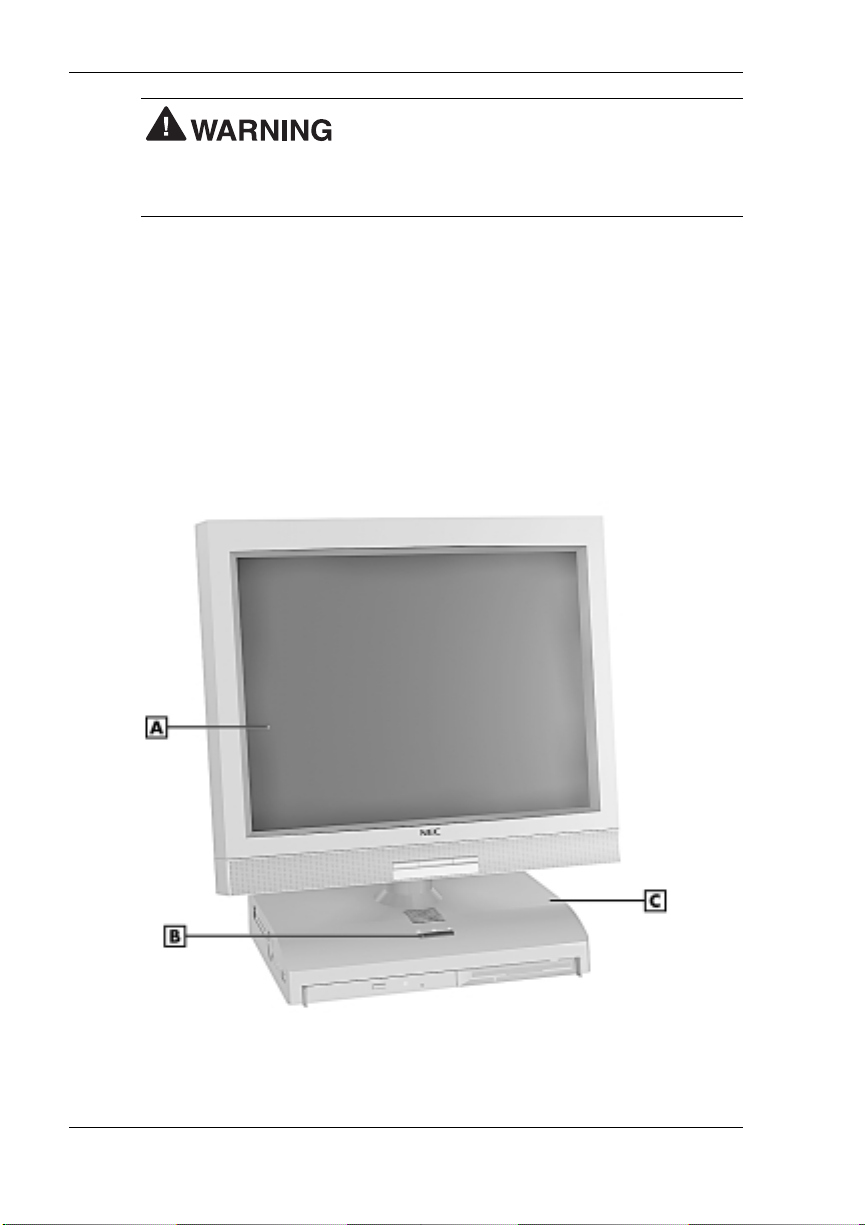
PowerMate 2000 System
A
– LCD Panel
B
– Power/Sleep Button
1-2 Revi ewing System Features
C
– System Unit
System uni t front fe atures
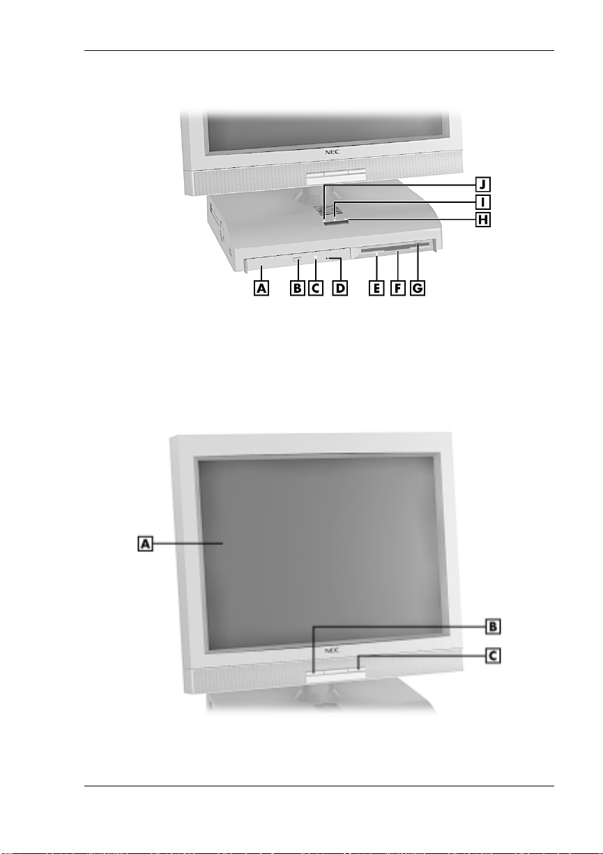
A
– CD-ROM Drive
B
– CD-ROM Eject Button
C
– CD-ROM Drive Lamp
D
– CD-ROM Disc Emergency Eject
E
– Diskette D r ive Lamp
LCD panel features
F
– Diskette Drive
G
– Diskette Eject Bu tton
H
– Hard Drive Lamp
I
– Power Lamp
J
– Sleep Lamp
A
– LCD Panel
B
– Decrease Brightness Level Button
C
– Increase Brightness Le vel Button
Reviewing System Features 1-3
System Controls and Lamps
System unit controls include a power/sleep button, power lamp, sleep
lamp, and hard drive activity lamp.
Power /sleep button
To turn system unit and LCD panel power on, pr ess th e power/sle ep
button. To turn off pow er, press the butt on an d h ol d in pla ce for four
or more seconds before releasing.
Do not turn off the system power until you have
cl osed al l app lic at ions and Windo ws or y ou may possi bly l ose data.
To su s pen d s ys tem unit and LCD pa nel opera t ion, press the
power/sleep button an d r elease within three seconds or less. Thi s
places the system unit and LCD panel in a power savings mode. Use
this fea ture if you pla n to be away from your s ystem for more tha n
15 minute s.
Do not hold the button in any longer than three
seconds or you will turn off the system and possibly lose data.
Press any key or move the mouse to resume s ystem opera tion at the
point where you stopped it.
Power an d sleep lam p s
The power lamp indicates if system power is on or off. The sleep lamp
let s you know if the system is oper ating in a p ower-s aving mod e .
A stead y green power lamp indi cates that the power is on to all system
components. An am ber sleep lamp indicates tha t the system i s in sl eep
mode with full-power reduction.
Hard drive activity lamp
A flash ing green lamp indicates tha t the hard drive is acti ve and is
readin g or wri t i ng data.
Do not turn off the system unless absolutely
necessary while t he hard drive lamp is flas hing . To do so can damag e
your hard drive or data.
1-4 Revi ewing System Features

LCD Panel
The syst em comes with an LCD panel that you can adjust up or d own and
side-to-side for a comfortable viewing position. The panel uses a 15-inch,
twisted nematic Thin Film Transistor (TFT) Super Video Graphics Array
(SVGA) color screen. The screen has a brightness of 200 candlepower
and a maximum resolution of 1024 x 768 pixels.
The LCD panel screen automatically turns on when you pr es s the system
power button. If you have an optional vid eo graphi cs arra y (VGA)
monit or attach ed to the system, the monit or can be turned on for
simultaneous viewing on the monitor and the LCD panel.
An increase brigh tness butt on and a d e c rea s e brightn ess button on the
panel allows you to increase or decrease the brightness of the display. The
buttons provide eight levels of brightness. The default brightness is
maximum.
Note
outlet changes any new brightness setting to the maximum default
brightness.
Powering off the system or unplugging the system from the power
Diskette Drive
Use the diskette drive to copy data files to and from a diskette. You can
also use it as a bo otable drive for loading a nd starting pr ograms from a
diskette.
A flashing gr e en activit y l amp on t he front of the dr ive indicates that the
drive is reading or writing data.
Press the eject button to eject a disk ette.
data, do not turn off the system or remove a diskette while the diskette
drive busy lamp is flashing.
To p reven t dama ge to the di skette drive and
Reviewing System Features 1-5

Hard Drive
The syst em comes with either a 6.0-giga b yte (G B) or a 12-G B enh anced
intelligent device electronics (EIDE) hard drive. The drive features ultra
direct memory access ( D M A) 66 technology for fa s t data transfer.
The drive is located inside the system unit, on the right side. The drive is
not user accessible.
Hard disk activity is indicated by a flashing green lamp on the front of the
system unit.
CD-ROM Drive
All systems come with a 24X Max Slim variable speed CD-ROM drive.
Use th e CD-ROM drive to load and start progr ams from a comp act disc
(CD). You can also us e the CD-ROM dr i ve to play your audio CDs.
The CD-ROM drive operates at differ en t speeds d ep ending on wh ether
the CD you are using contain s data or music. This all ows you to get your
data faster and to see smoother animation and video.
A flashing amber activity lamp on the front of the drive indicates that the
drive i s reading data. Press the tray button to open or close the CD - ROM
tray for loading or unloading a CD. An emergency eject feature allows
you to open the tray in c ase of a power or software ma lfunc tion .
Speakers
The syst em has two 1-watt ster eo sp eakers mou n ted inside the base of the
LCD pan el. Speaker volume is control led by the volume cont r ol on the
left side of the system unit. Volume can also be controlled through the
Windows sound software.
Left Side Features
The foll o wi ng fig ure shows the fea tures on the left si d e of the system un it.
Brief descriptions of the features follow the figure.
1-6 Revi ewing System Features
Left side features
A
– PC Card Slot 1
B
– Slot 1 Card Eject Button
C
– Slot 2 Card Eject Button
D
– PC Card Slot 2
E
– Fan
Audio Connectors
The syst em unit ha s the following audi o connector s :
Micr ophone in ja ck
Use thi s jack to connect a micr ophone for r ecording au di o information
in your data files.
Line in jack
Use thi s jack to connect a stereo a u d io device such as a ster eo
amplifier or a c assette for playback or re cordi ng.
Headphone jack
Use thi s jack to connect an opti on al headphone set. Pluggin g in the
headphone set di s ables th e bu il t-in system s p eakers .
F
– Microphone In Jack
G
– Line In Jack
H
– Headphone Jack
I
– Vol u me Co n tr ol
J
– System U nit
Reviewing System Features 1-7

Volume Control
Use the volume control to adjust the volume of the system’s built-in
speakers or opt ional hea dphone set. Th e s p eakers are located in the base
of the LCD panel.
You can also use the Windows sound software. To bring up the Windows
volume control, double click the speaker icon on the taskbar (next to the
system cl ock). Use t he software to bal ance the sound between the left an d
right speakers.
PC Card Slots
Your system has two PC card slots that support 16-bit PC card technology
and 32-bit CardBus technology. The CardBus technology provides up to
132 MB/second of bandwidth.
The card slots support two Type II cards or one Type III PC card in the
bottom slot for extending the system’s capabilities. Each type of PC card
has a differ ent funct ion. Using the PC c ard slots, you can add a n umber of
funct ions to th e s ystem wi th a vari ety of cards (for example, modem,
memory, Small Computer System Interface).
A PC card is inserted into a PC card slot similar to inserting a diskette in a
diskette drive. Press the eject button to eject a PC card.
Removabl e s lot covers keep foreign m a tter ou t of the slots wh en PC cards
are not used.
Fan
The fan cools system unit comp onents and prevent s them from
overheatin g. Keep the area near th e fan clear for pr op er ventilation.
A feature of the fan is it s quietness. The fan operates at less t han 30 db.
Rear Features
On the rear of the syst em unit ar e the univer sal serial bus (USB) ports, DC
power connect or, mouse an d keyb oa rd ports, and other exter nal device
conn ectors. The following figure shows th e ports and connector s .
Descriptions of each follow the figure.
1-8 Revi ewing System Features
Rear features
A
– PS/2 Mouse Port
B
– Kensington Lock Slot
C
– PS/2 Keyboard Port
D
– Pri nter Por t
E
– Serial Port
Universal Serial Bus Ports
The syst em unit com es with two USB ports on the rear of the s ystem unit.
The ports allow you to easily and conveniently add plug and play USB
devices without opening up the system. You simply plug the USB device
into a por t. You c a n connect up to 127 USB de vices i ncl uding a keyboard,
mouse, monitor, printer, scanner, or speaker set.
DC Power Connector
The syst em operat es with DC power suppli ed from the AC power adapt er .
The adapter plugs into an AC p ower s ource an d the DC power connector
on th e rear of the system unit. Th e A C power adapt er u s es a s tandard
115-Vac or 230-Vac grounded power source.
F
– VGA C onn e ctor
G
– LAN Connector
H
– USB Connectors
I
– DC Power Connector
Reviewing System Features 1-9

PS/2 Mouse Port
The system unit comes with a mouse port that supports a
®
-compatible (personal system/2-compatible) mouse with a 6-pin
PS/2
mini D I N connector .
Use this port to connect the PS/2 mouse shipped with your system.
PS/2 Keyboard Port
Your system unit com es with a ke yboard port that supports a standard
PS/2 101-key or 104-key keyboard with a 6-pin mini DIN connector.
Use t his port t o conne ct th e PS/2 keyboard shippe d with your s ystem .
VGA Monitor Connector
The syst em unit com es with a VGA conn ector on the rear of th e system
unit.
Use thi s con nector t o connect an op tional NE C M ul tiSync
VistaScan™ monitor, or other VGA- compatible monitor with a 15-pin
conn ector. You can also atta ch a projector wi th a 15-pin connect or to this
connector.
The system supports simultaneous use of the LCD panel and an optional
monit or con nected to the VGA connector.
®
monitor, NEC
Printe r Port
Use thi s p or t to connect a parallel printer with a 25-pin connector to the
system unit. The port is an enhanced capabilities port (ECP). It also
supports enhanced parallel port (EPP) bi-directional and uni-directional
protocols.
Serial Port
Atta ch a serial devi ce wi t h a 9-pin con nector to th i s s er ial port. S er ial
devices incl ud e a p ointing device, serial printer, or a modem.
1-10 Revi ewing System Features
LAN Connector
Systems come with a local area n etwork (LAN ) . Use the RJ-4 5
compat ible LAN con nector on the rear of the system to connect a n etwork
cable to the internal 100Base-TX/10Base-T network board.
Bottom Features
A panel on t he bot tom of the system unit c overs the m e mory exp ans ion
sockets and the pa ss w ord clear jumper. (See Chapter 4, “Adding
Expansion Devices,” for information on removing the panel.)
Bottom features
A
– SO-DIMM Socket 1
B
– Password Clear Jumper
C
– SO-DIMM Socket 0
Reviewing System Features 1-11

Memory Sockets
The syst em unit com es with at lea s t one 64-MB sm all outline dual-inline
memory module (SO-DIMM) mounted in one of two memory sockets.
You can increase total system memory to a maximum of 512 MB by
using two 256-MB modules (see “Adding Memory Modules” in
Chapter 4).
The modules use synchronous dynamic random access memory
(SDRAM). Memory allocation is controlled by Dynamic Video Memory
Technology (DVMT). With DVMT, total system memory is shared
between s ystem memory and video memory. For exampl e, with 64 MB of
total system memory, 56 MB might be allocated for system memory and
8 MB for video memory, with actual memory use dependent on video
usage.
Password Clear Jumper
Use th e password cl ear jumper ( 7F4) to clear your password if you for g ot
it. To clear and reset the password, see “Jumper Settings” and “Security
Menu” in Chapter 3.
Microdesktop Chassis
The NE C Microdeskt op chassis conform s to NEC’s Very-Small Form
Factor and Flat Panel Display Specification. The microdesktop h as the
following features:
small size chassis that is 85 percent smaller and correspondingly
lighter than traditional desktops
15-inch LCD panel with 1024 x 768 pixel maximum resolution, eight
levels of d isplay brigh tness , hor i zont al viewing angl e of 60 de grees
from cen ter to r ight or left s ide of p a nel , ve rtical viewing ang le of 40
degrees from center of panel and upwards and 50 degrees from center
of panel and downwards
90-watt power supply (built into the AC power adapter).
1-12 Revi ewing System Features

System Overview
The syst em hardware and softwa re deliver the performan ce and
technologies needed for all your ch allenging tasks today and int o the
future.
Hardware
The PowerMate 2000 Series includes the following hardware features:
PC99 Compliance
All the hardware in the system is certified by Microsoft
compliant.
Processor
The syst em comes with an Intel
front si de bus). Th e processor is a fas t , powerful processor t hat l ends
itself to computational, graphical, and networking tasks.
Audio
The system board comes with an integr ated audi o s ubsys tem. The
audio chipset gives you a surround sound system for threedimensiona l s ound effects . It also provides wavetable synthesis.
Flasha ble ROM BIOS
The system’s ROM BIOS features system setup configuration, Plug
and Play support, and flash support for economical BIOS upgrades.
®
to be PC99
®
Pentium® III processo r (100-MHz
System and Video Mem ory
Your system comes with at least 64 MB of non-ECC PC100 SDRAM
and supports up to 512 MB of total system memory. The memory uses
DVMT technology which allows system memory to be shared with
video memory. For example, with 64 MB of total system memory,
56 MB might be allocated for system memory and 8 MB might be
allocated for video memory (actual usage depends on video usage).
AGP Graphics
The syst em comes with an accelerated graphics port (AGP) in tegrated
on th e system board . AG P enhances graphics performance,
particularly for 3-D applications.
Power Management Options
Power management options extend the life of your LCD panel,
conser ve energ y, and reduce p ower costs.
Reviewing System Features 1-13

Software
NEC provides a variety of software applications and hardware utilities
with your system to let you take advantage of your hardware capabilities.
Preloaded Microsoft Operating System
Your system comes preloaded with the Microsoft® Windows® 98 SE
operat ing syst e m or with a d ual- boot Windows NT
2000 operating system.
NEC OS Restore CD
Your system comes with an NEC OS Rest ore CD and boot able diskette.
The CD con tains th e Windows 98 operating system or the dual- boot
Windows NT/Windows 2000 operating systems, depending on your
model.
Shoul d a problem occur that ca uses data loss or corrupti on, you can
res tore your s ystem to it s original factory sta te or you c an re s tore j ust the
opera ting system and drivers. You can also perform hard drive
partitioning.
After restoring the operating s ystem, you can use the A p pl ication and
Driver CD to install your applications, drivers, and NECC online
documents.
NEC Application and Driver CD
Your system comes an NEC Application and Driver CD. Use this CD to
inst all any or al l of the software that com es wi th the s ystem, in cluding:
Microsoft® Interne t Expl orer Browser
Internet Explorer provides a top-notch browser with preloaded links
for ea sy access to th e wor ld wide web. Also use Internet Ex p lorer to
acces s one of the ma ny new browse r-based utiliti e s .
®
4.0 and Windows
®
Norton AntiVirus™ 2000 Software
Protect the system from virus es by run nin g Nort on’s virus scan
software.
1-14 Revi ewing System Features

Adobe® Acr obat® Reade r
Use th e Adob e Acrobat Rea d er to read an d print por table document
format (PDF) files found on the Internet and PDF documents included
with various software applications.
Intel LANDesk® Client Manager
Use LANDesk software to track system information such as serial
number, BIOS version, memory capacity, disk capacity, expansion
board setting s, and applications. Use LANDesk software for remote
star ts from a server comput er using Wake- On LAN and remot e r ebo ot .
NEC INFO Center
The NEC INFO Center an online version of this user’s guide, an d
Tour, Questions, Solutions, and Services modules.
Select the Tour module to look at the documentation, tools, and
services that come with th e system. Th e Q u es tions modu le includ es
answers to frequently asked questions. Use the solutions module to
find possible solutions to system problems. The Services module
conta ins servi ce inform ation such as where to go on th e Intern et for
help, who to call for service, and more.
A wide selection of drivers
Drivers for hardware that is compatible with PowerMate series
comput ers are pr ovi d ed wi th the or iginal man u facturer ’s installa tion
wizar d s to ensure correct installa tion.
Security
The system has hard wa re, software, and mechanical security features th at
offer pr otect ion a gain s t unaut horized acc e s s to your s ys tem and da t a. The
follo wing security featu res are a va ilable with the system.
Password security
The BIOS Setup utility includes a feature that lets you set a user or
supe rvisor password, or both.
The user password control s booting of the system an d controls acces s
to the Setup util ity and th e keyboa rd. (User access t o the BIOS Setu p
utility is limited to a subset of all BIOS Setup parameters when a
supervisor password has been set.)
The sup ervisor pa s sw ord all ows full access to the syst em and the
BIOS.
Reviewing System Features 1-15

Security Lock Slot
The security lock slot on the rear of th e system accept s a Kensin gton
Security Stan d ar d connect or or other locking devi ce. Secur e the
locking device to the security lock slot and to an immovable object to
pr otect your s ystem from theft .
Hard Drive Security
Your system supports password protection for the hard drive. Hard
drive password protect ion restricts access to the dr ive if the drive is
removed and installed in an other sys tem. The s ystem does not prompt
for hard drive passwords while th e drive remains in the current
system.
The pa s s wor d s are written to the system BI OS and to th e hard drive t o
ensure that the password protection travel s wi th the hard drive in the
event it is moved to an ot her system . (See “Hard Drive Security” in
Chap ter 3 for addi tional in formation on using this feature.)
Wind ows network s ecu rity features
To learn more about the network security features available through
the Windows oper ating system , refer to your Windows docum entati on
or consu lt your system ad m i nistrat or.
®
1-16 Revi ewing System Features

Setting Up the System
Cable Connections
Startup
Shutdown
Power-Savi ng Op era tion
Syste m Care
More Informatio n
2

This cha pter provid e s basic informa t ion for set tin g up and us i ng your
system ( refer t o th e Quick Setup poster for details) . Includ ed ar e cable
conn ections, s ystem star tup procedures, system shutdown procedu res, and
system ca re. The chapter also includ es a table showing where t o find
additional information about your system.
Cable Connections
After unpacking the system (save the carton) and positioning the system
in your work area, con nect the system components using the Quick Setup
poster and the following tips.
Use the icons on the rear and side of the system unit to identif y th e
USB, keyboard, mouse, LAN, printer, monitor, power, and audio
connectors.
See your n e twork adm inist rat or for gu ideline s on configuring the
LAN.
Connect the system A C ad apter power cord to a surg e protector
(recom mended ) or a properly ground ed wall outlet and to th e DC
power connect or at the rear of the system unit.
NECC recommends connect ing t he AC ad apter
power co r d to a su rge pr otec tor t o protect y our sy s tem.
Startup
Press the power button to turn on the system unit and LCD panel. The
power l amp lights green to indicate that the system is on. The system
performs its Power-On Self-Test (POST) and several messages appear on
the screen indicatin g that the system is check ing its su bsystems.
Note
appears:
Setu p Uti lity, immediately press
Chapter 3, “Configuring the System,” for information on using the BIOS
Setup.)
After a short delay, Win d ows st arts up.
2-2 Setting Up the System
At t he bottom of the NEC startup s creen, th e f ollowin g mess age
Press F2 to enter BIOS Setup
F2
. If you want to enter the BIOS
whil e the start up scr een di spla ys. (See
If a proble m occurs, a s eries of beep s might sound. I f t his h appen s
repeatedly after powering on, power off the system and go to Chapter 5,
“Solving Syst em Problems.” T he chapter provi des help ful hints for
solving system problems.
If the system displays a messag e indi cating that system settings have
changed, run the BIOS Setup Utility (see Chapter 3, “Configuring the
System”).
On system s loaded with the Wind ows N T
opera ting system , press
The log- on box appears for ent ering a password.
Shutdown
Follow t hese step s to power off the system.
a sy stem i n sleep mode, save and cl ose any open applicat i ons, exit
Windows, and power down the system.
1.
If the system is in sleep mode (sleep mode lamp amber), move the
mouse or press a key to ta k e it out of sleep mode (see “Power Saving
Operation” in the next section).
®
4.0 or Windows 2000
Ctrl Alt Del
To p reven t damage to system components, wak e
when prompted on-screen to do so.
2.
Save and e xit all your open appli c ations.
3.
Make sure that the hard drive, disk ette drive, and any oth er d rives are
not in us e. A lit device l amp indi cates that the device i s in use.
Wait until all open applications are saved and
cl osed befor e usin g the Windo w s shut down procedur e i n step 4.
Unless absolutely necessary, never power off the system if the system
sl eep lamp is amber , i f either the hard drive lamp, d iskette drive, or other
device lamp is flashing, or if any applications are open. Information on the
device might be lost or damaged.
Setting Up the System 2-3

4.
Start
Click
the computer
on the taskbar and click
, then click
Yes
or pr e s s
dependi ng on you r ope rating system.
If the system is configured with Windows 98 or Windows 2000,
the syst em shut s down automatically aft er a shor t interval.
If th e s ystem is confi g ured with Windows NT, and after you
perform a Windows shut down, power off the system by pressing
and holding in the power button for four seconds or longer
before releasing.
Power-Saving Operation
If the system is running Windows 98 or Windows 2000, you can put it in
sleep mode (a power-saving state) by pressing and immediately releasing
the power butt on on th e front of th e system unit. The sleep mod e is a
convenient way of conservi ng ener g y when you are g oing to be awa y
from your system for more than 15 minutes.
Tak e car e t o pres s and immediately release the
power bu t ton to enter the sleep mode. Avoid pressi ng and holding i n the
power button longer than three seconds or you may turn off power and
possibly lose data from any open applications.
Shut Down
Enter
for shut down,
. Select
Shut down
The syst em also goes into sl eep mode when it has been inact ive, if the
power management has been enabled in BIOS, and an inactivity timeout
has been enabled. (See Chapter 3, “Config uring Your S ys tem,” for
information on setting power management functions.)
When the system goes into sleep mode, it automatically saves data and
system statu s and then shu ts off power to all possible compon ents. Sleep
mode lets you save power without firs t s avin g your work.
An amber s leep lamp in di cates that the system is in sleep m od e. Press a
key or move the mouse to resume system operation where you left off.
2-4 Setting Up the System

System Care
The system is a durable system built for dependable use. With protective
mea s ures a nd pr oper care, you can prevent problems and promote the
successful operation and long life span of the system.
Protecting Your System From Damage
There are several ways tha t you can prot ect the system from p ossible
damage. NECC strongly recommends the following protective measures.
Connect a surge s u ppressor bet w een the system and a grou nded wall
outlet. A surge suppressor protects the system from sudden transient
increases and decreases in electr ical power.
Be sure t o connect al l p eripher als, such as a printer , to the surge
suppressor. The surge protector should be the only device that you
plug into the wall outlet.
Avoid r ep eated power -on cycles. These subject the system
components to temperature variations and stress.
Discon nect the s ystem from telephon e an d power lines when an
electrical storm thr eatens. If you h ave a fax/modem, lightnin g can
travel in on the phone line and damag e both the fax/mod em an d the
system u n it. Ligh tn ing can also travel in on power lines and dam age
the LCD panel and system unit.
Be sure th at system p ower is off bef ore connectin g or d isconnecting a
cable (US B devices d o not require poweri n g down the system when
conn ecting). Never make ca bl e ch anges wh en the system power is on.
Doing so can damag e the system and its per ipherals.
Use BIOS Setup Utility options to protect against viruses (see
Chapter 3). You shou ld al so use the Norton vi rus sc an protection
software pr ovided with the syste m to p rote c t th e system from vi rus es.
If you plan to use software programs ot her th a n NEC C-su ppli e d
softwa re, NECC strongly r ecom mends that you take the necessary
steps, such as vir us checks, to protect th e s ystem .
Position the system away from direct sunlight and extreme hot and
cold temperatures.
The recom mended op er ating environm en t is from 50°F to 95°F (10°C
to 35°C).
Setting Up the System 2-5
Loading...