

No.99MBE032A5
SERIES No.174
KA Counter
KA Counter
for Linear ScaleUnits
User’s Manual
Read this User’s M anua l thor ough l y
before operating the i nstr um ent. After read ing,
retain it close at hand f or f uture refer ence .
CONVENTIONS USED IN THIS MANUAL
Safety Precautions
To ensure that instruments are operated correctly and safely, Mitutoyo manuals use
various safety symbols (Signal Words and Safety Alert Symbols) to identify and warn
against hazards and potential accidents.
The following signs indicate general warni ngs:
Indicates an imm inently hazardous situation whic h, if not avoided, will result in ser ious
DANGER
WARNING
injury or death.
Indicates a potent ially hazar dous situation whic h, if not avoide d, could result i n serious
injury or death.
CAUTION
Indicates a potent ially haza rdous situatio n which, if not avoided, m ay result in m inor or
moderate injury or property damage.
The following signs indicate specific warnings or prohibited actions, or indicate a
mandatory action:
Alerts the user to a specific hazardous s ituation. The given example m eans “Caution,
risk of electric shock”.
Prohibits a specific action. The given example means “Do not disassemble”.
No. 99MBA040A
Specifies a required action. The given example means “Ground”.
i

CONVENTIONS USED IN THIS MANUAL
Types of Notes
The following types of notes are used in this manual to hel p the operator obtain relia ble
measurement data through correct instrument operation.
IMPORTANT
NOTE
TIP
• An important note provides information essential to the completion of a task. You cannot
disregard this note to complete the task.
• An important note is a type of precaut ion, which if neglected co uld result in a loss of
data, decreased accuracy or instrument malfunction/failure.
A note emphasizes or s upplements important points of the main text. It also suppl ies
information about specific situations (e.g., memory limitations, equipment
configurations, or details that apply to specific versions of a program).
A tip is a type of note that helps the user apply the techniques and procedures described
in the text to his or her specific needs.
It also provides reference information associated with the topic being discussed.
Mitutoyo assumes no liability to an y party for any loss or dam age, direct or ind irect,
ii
caused by use of this instrument not conforming to this manual.
Information in this document is subject to change without notice.
2003 Mitutoyo Corporation. All rights reserved.
No. 99MBA040A
SAFETY PRECAUTIONS
Be sure to read this section and obey the following precautions in order to use the counter
safely.
WARNING
• This counter is intended to be used with general measuring instruments, machine tools,
etc. Do not use this counter with control equipment associated with medical
instruments, aerospace eq uipment, nuclear-energy relate d equipment or the like that,
due to malfunction or accident, could cause injury or death. Consult with Mitutoyo
before using it in such equipment.
• Risk of fire or electric shock. If there is smoke or bad odor coming from the counter, or if
the counter is not operating properl y, imm ediately turn OFF the m ain power swi tch on
the rear panel and unplug the power cord, then contact the dealer for repairs.
• Ris k of fire or el ectric shoc k. If the cou nter is drop ped or dam aged, turn OFF the main
power switch on the rear panel and unplug the power cord, then contact the dealer.
• Risk of fire or electric shock. The user should absolutely not repair or modify the
counter.
CAUTION
• If something gets inside the counter, first turn OFF the main power switch on the rear
panel and unplug the power cord, then contact the dealer.
• Be sure to use the specified power-supply voltage. Operating the counter on other
voltage than the specified could cause circuit failure, fire or electric shock.
• Do not expose the counter to direct sunlight or to excessively hot areas. The
temperature inside the counter could rise, causing fire.
• Do not place t he counter direc tly against a wall or the like. The tem perature inside the
counter could rise, ca using counter failure. Place t he counter at least 10 cm from the
wall so that the power cord can be removed easily.
• Be sure to ground the counter by connecting to the machine tool with the supplied
ground lead. This prevents the counter from malfunctioning.
No. 99MBA040A
iii

WARRANTY
In the event that the Mitutoyo KA Counter should prove defective in workmanship or
material, within one year from the date of original purchas e for use, it will be repaired, at
our option, free of charge upon its prepaid return to us.
This warranty shall n ot apply if the product has been s ubject to fair wear and tear, abuse
through misuse or im proper use/handling/storage/m aintenance/service/repair or through
adaptation/modification by the original purchaser or an y third part y without prior written
consent of Mitutoyo or as a result of damage by an actual disaster or circumstances
beyond the control of Mitutoyo.
To obtain service under this warranty the product must be returned to the nearest Mitutoyo
Service Center. Any postage, insurance, or shipping charges incurred in returning the
product for service are the responsibility of the purchaser.
* This warranty is not transferable and is only valid within the country of the original
purchase.
* You may have additional rights under the laws of country of original purchase that do not
allow the exclusion of implied warranties or the exclusion or limitation of certain
damages. If these la ws apply, Mitutoyo’s limitations and exclusions may not apply to
you.
iv
No. 99MBA040A

CONTENTS
CONVENTIONS USED IN THIS MANUAL.........................................................................................................i
SAFETY PRECAUTIONS .................................................................................................................................iii
WARRANTY......................................................................................................................................................iv
CONTENTS........................................................................................................................................................v
1 INTRODUCTION.................................................................................................................................... 1-1
1.1 Outline ....................................................................................................................................................1-1
1.2 Name and Function of Each Part .........................................................................................................1-2
1.2.1 Main unit.................................................................................................................................................1-2
1.2.2 Display....................................................................................................................................................1-4
1.2.3 Name and function of keys for the standard counter.........................................................................1-5
1.2.4 Name and function of keys for the lathe counter ...............................................................................1-6
1.2.5 3-axis counter........................................................................................................................................1-8
2 SETUP.................................................................................................................................................... 2-1
2.1 Opening the Package............................................................................................................................2-1
2.2 Installation..............................................................................................................................................2-2
2.3 Connecting to the Counter ...................................................................................................................2-3
3 BASIC OPERATION.............................................................................................................................. 3-1
3.1 Explanatory Notes.................................................................................................................................3-1
3.2 Basic Operations in the Standard Counter .........................................................................................3-2
3.2.1 Turning ON/OFF the power...................................................................................................................3-2
3.2.2 Counting and displaying.......................................................................................................................3-4
3.2.3 Switching the coordinate......................................................................................................................3-5
3.2.4 Zero-set..................................................................................................................................................3-5
3.2.5 Preset.....................................................................................................................................................3-5
3.2.6 Saving and recalling a datum point using the scale reference point
(When the AT100 series is connected.) ...............................................................................................3-8
3.2.7 Setting the machine origin using the AT700 series ..........................................................................3-11
3.2.8 Datum setting, centering and measuring with the touch signal probe
(Possible only when the AT100 series is connected.)......................................................................3-13
3.2.9 Halving the display..............................................................................................................................3-16
3.2.10 Bolt-hole circle machining..................................................................................................................3-17
3.2.11 Pitch machining...................................................................................................................................3-21
3.2.12 Zero approach machining...................................................................................................................3-24
3.2.13 Changing the unit of measurement...................................................................................................3-25
3.2.14 Addition mode.....................................................................................................................................3-26
3.3 Outline of the Lathe Counter..............................................................................................................3-28
3.3.1 Setting parameters for the lathe counter ..........................................................................................3-28
3.3.2 Lathe counter operation modes.........................................................................................................3-28
3.3.3 Configuration of coordinates.............................................................................................................3-29
3.3.4 Setup for tool offset............................................................................................................................3-29
No. 99MBA040A
v

3.3.5 Count mode......................................................................................................................................... 3-31
3.3.6 Zero-setting/Presetting...................................................................................................................... 3-32
3.3.7 Tool number switch............................................................................................................................ 3-32
3.3.8 A/I coordinate switch..........................................................................................................................3-33
3.3.9 Halving the display............................................................................................................................. 3-35
3.3.10 Zero approach machining.................................................................................................................. 3-36
3.3.11 Changing the unit of measurement................................................................................................... 3-38
3.3.12 Saving and recalling a datum point using the scale reference point............................................. 3-38
3.3.13 Setting the machine origin using the AT100 series......................................................................... 3-38
4 PARAMETERS....................................................................................................................................... 4-1
4.1 Overview of Parameters .......................................................................................................................4-1
4.2 Types of Parameters .............................................................................................................................4-2
4.2.1 Parameters set for each axis............................................................................................................... 4-2
4.2.2 Parameters common to all axes.......................................................................................................... 4-6
4.2.3 Special parameters............................................................................................................................... 4-8
4.2.4 Display resolution when used for the AT100 series........................................................................4-10
4.3 Parameter Settings..............................................................................................................................4-13
4.3.1 Checking the parameter settings...................................................................................................... 4-13
4.3.2 Setting parameters for each axis ...................................................................................................... 4-14
4.3.3 Setting parameters common to all axes........................................................................................... 4-16
4.3.4 Parameters for the lathe counter mode............................................................................................ 4-18
4.3.5 Initializing the internal memory......................................................................................................... 4-19
4.3.6 Display contents and parameters in the addition mode..................................................................4-20
5 MAINTENANCE..................................................................................................................................... 5-1
5.1 Troubleshooting....................................................................................................................................5-1
5.1.1 Error messages .................................................................................................................................... 5-1
5.1.2 Error messages in the addition mode................................................................................................. 5-1
5.1.3 Wrong key operation............................................................................................................................ 5-3
5.1.4 Troubleshooting....................................................................................................................................5-3
5.2 Daily Maintenance for the Counter ......................................................................................................5-4
6 SPECIFICATIONS.................................................................................................................................. 6-1
6.1 Main Unit ................................................................................................................................................6-1
6.2 Connector Specifications.....................................................................................................................6-2
6.3 Accessories ...........................................................................................................................................6-2
6.3.1 Standard accessories........................................................................................................................... 6-2
6.3.2 Optional accessories............................................................................................................................ 6-3
6.4 Precautions for Using the Code Out Unit............................................................................................6-3
6.5 Precautions for Using the Linear Scale Adapter and Micrometer Head Adapter.........6-3
6.6 Conformance to CE...............................................................................................................................6-4
SERVICE NETWORK
vi
No. 99MBA040A

1 INTRODUCTION
1
1.1 Outline
The KA Counter shall be connected to the following Mitutoyo linear scales:
・Optical scale : AT100 series
・Electromagnetic ind uc tio n sc ale : AT700 series
This chapter describes the name and function of each part.
The user is allowed to cho ose either of the “standard counter” or “lathe counter” modes
through the modification of related parameter.
In addition, it has incor porated various us eful functions that c an meet various needs at a
machining shop, thus realizing a general-purpose multi-performance counter.
No. 99MBE032A
1-1
1.2 Name and Function of Each Part
The name and function of each part of the KA counter is given below.
On this product the user c an switch between the “standar d counter” and “lathe counter ”
modes through the s election of related parameter. Since each counter has the specific
display method and key functions, refer to the descriptions corresponding to each counter.
For the method of switching the counter model, refer to Section 4.2.2, Parameters
commonly set on all models.
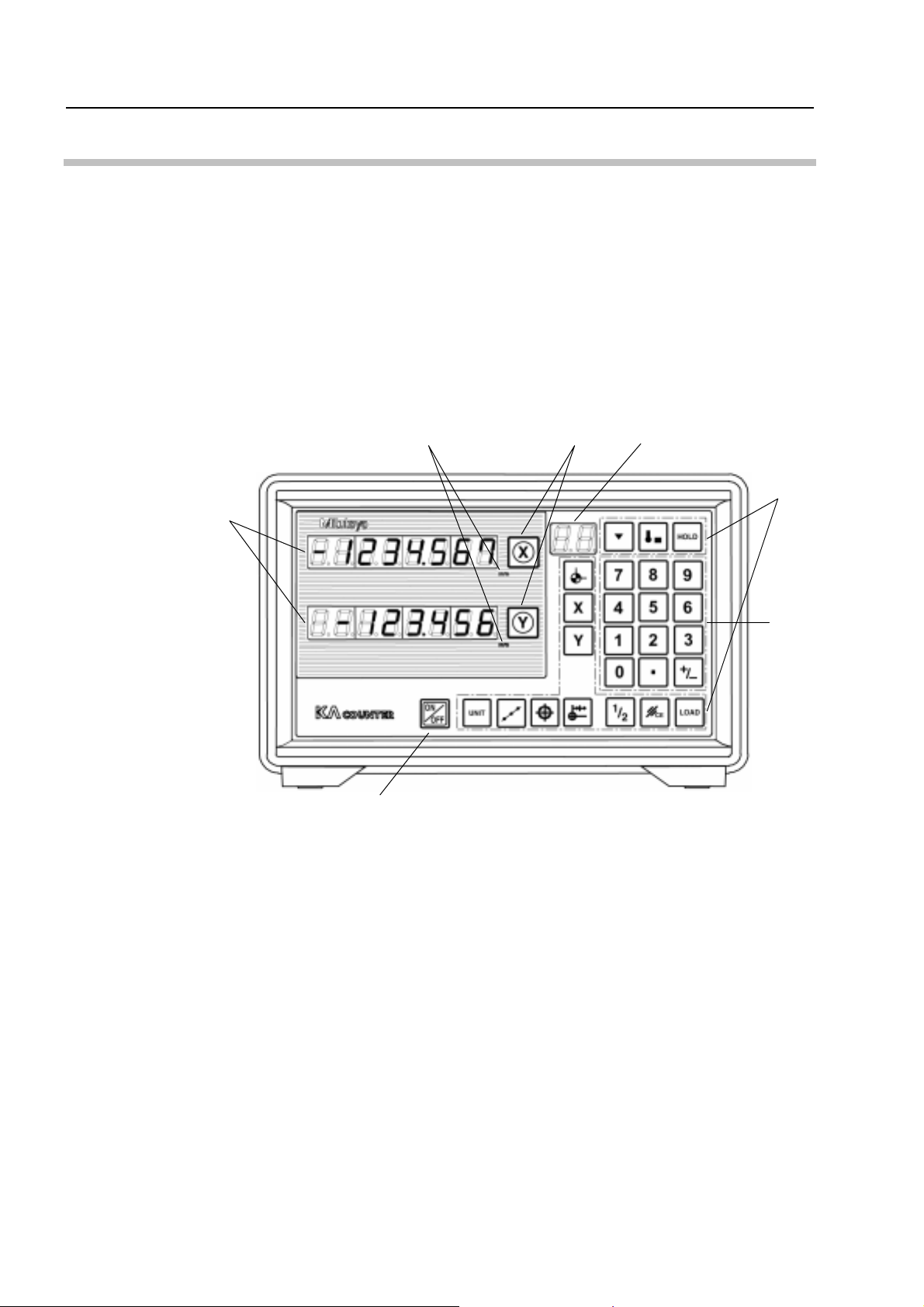
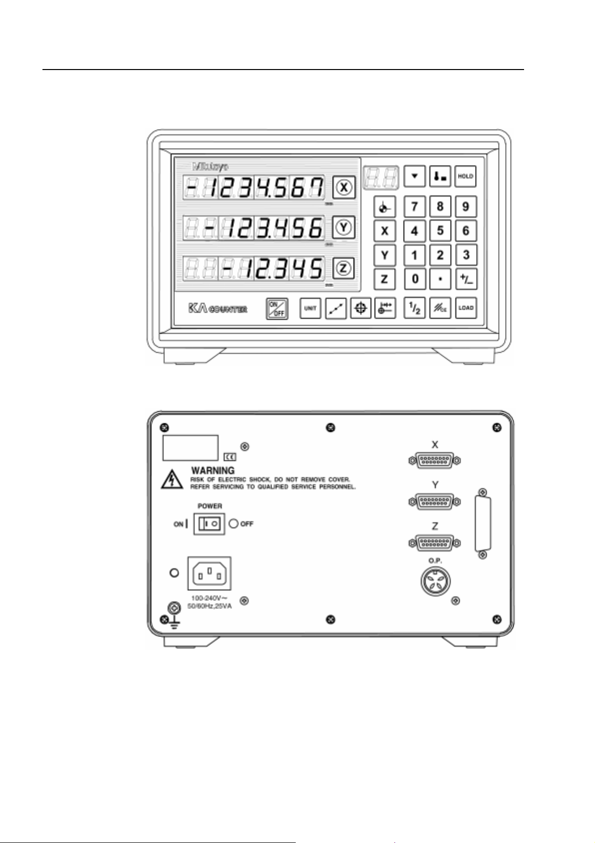
1.2.1 Main unit
1) Front panel
1
1 Display: Displays the values for the X-, Y-, and Z-axis, with a 1-digit sign and
7-digit number.
2 Sub-display: Displays set coordinates and display units.
3 Zero reset key: Resets the display for each axis to zero.
4 Ten-key pad: Keys used for entering numerical data.
5 Function keys: Keys for controlling the normal basic functions.
6 Display ON/OFF switch: Turns ON/OFF the display on the front panel.
7 Counting unit display: Displays the set unit of measurement.
6
7
3
2
5
4
1-2
No. 99MBE032A
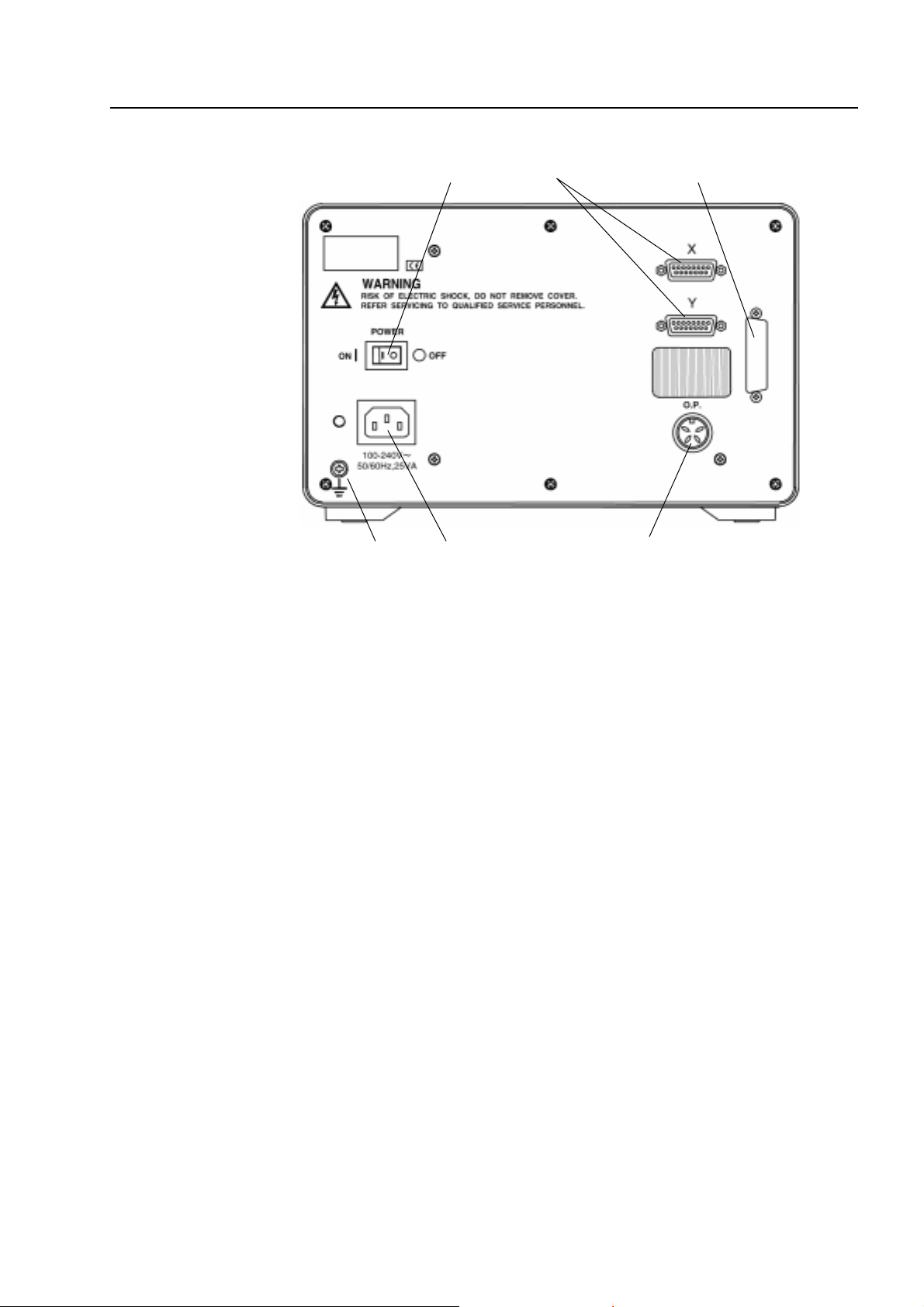
2) Rear panel
1. INTRODUCTION
1 AC inlet: Connects to the power cord.
2 Main switch: Main switch for turning ON/OFF the power.
3 Linear scale input connectors: Connect the X-, Y-, and Z-axis scale units.
4 Touch signal probe connector: Connects the touch signal probe.
5 Ground terminal: Terminal for connec ting to the grounding wire for gr ounding the
6 RS232C code out unit installation: For installing an optional RS232C code out unit.
51
main unit.
4
6 32
No. 99MBE032A
1-3
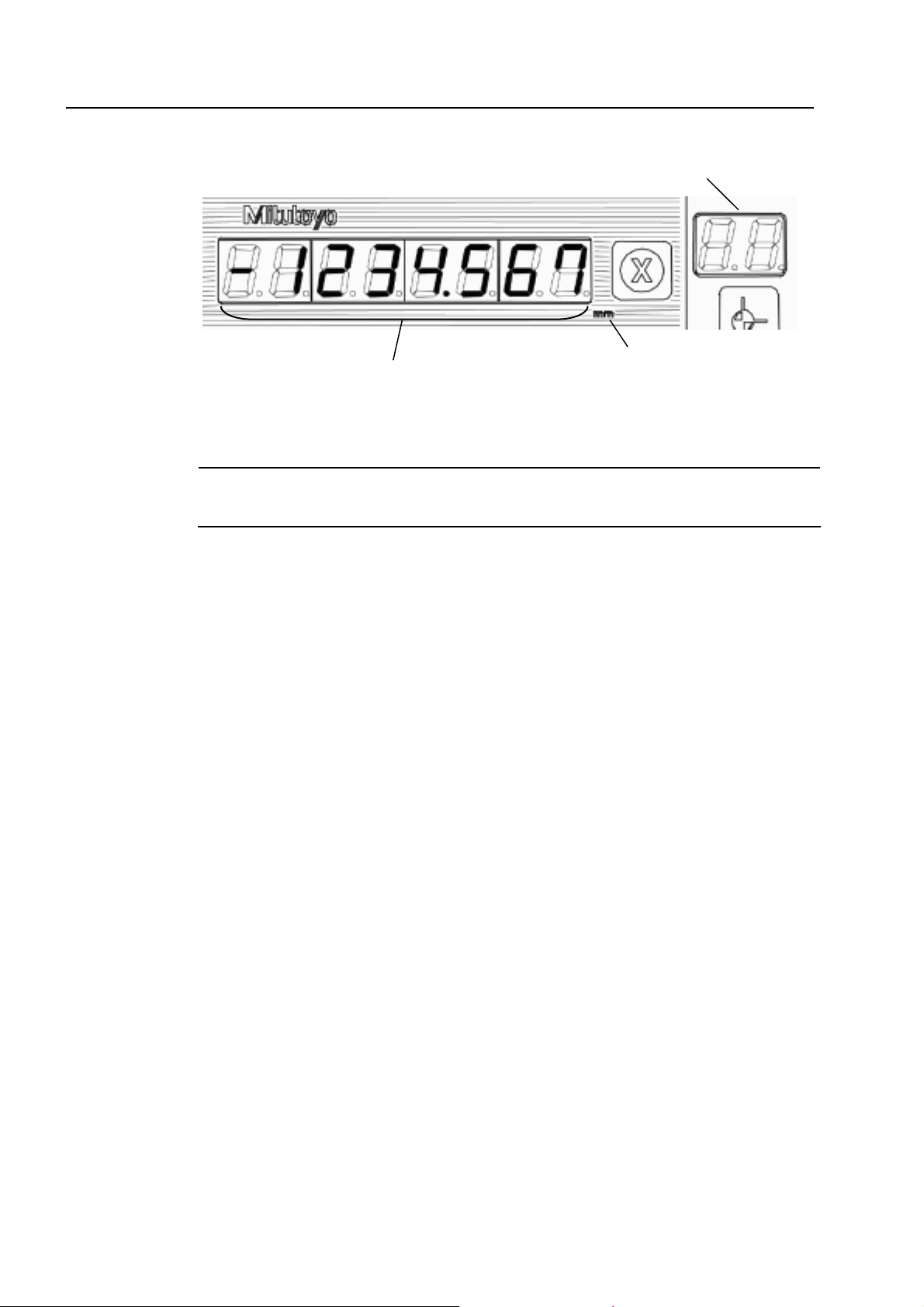
1.2.2 Display
1
2
3
1 Data display: Displays a 7-digit number (maximum) and decimal point.
2 Counting unit display: Displays the set unit of measurement.
NOTE
This display is only used when “mm” is selected. Nothing is displayed when inch or
1/25.4 is selected.
3 Shows the displayed coordinate number. This can be used to show the operation
mode.
1-4
No. 99MBE032A
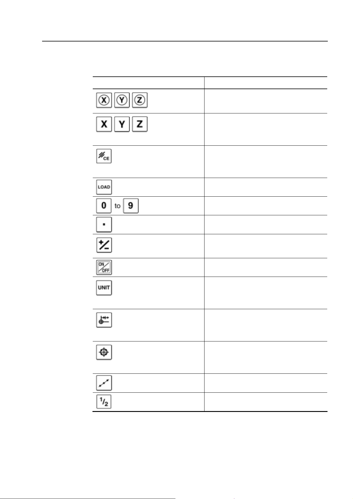
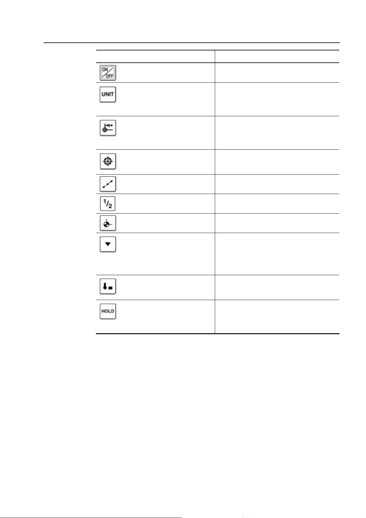
1.2.3 Name and function of keys for the standard counter
The name and function of the function keys and ten-key are given below.
Symbol and name Function
Zero-set k ey Resets the displayed value of the specified
axis to zero.
1. INTRODUCTION
Axis-designation
key
Cancel key • Cancels the number being entered.
Load key Loads the entered values.
Number keys Used to enter numbers 0 to 9.
Decimal-point key Sets the decimal point.
Sign key Switches the en tered number to negative or
ON/OFF switch Turns ON/OFF the display on the counter.
Display-unit switch key Switches the display unit.
• Designates the axis to be set.
• Calls up the previous setting.
• Enables ten-key input.
• Cancels the operation being executed.
• Cancels the error.
positive.
If mm is select ed, then the mm displa y ligh ts
up.
No. 99MBE032A
Zero-approach key The target value is automatically displa yed,
Bolt-hole circle key (av aila ble
with 2- and 3-axis counter)
Pitch machining key Used to perform a pitch machining.
1/2 key Halves the displayed value.
and sets the function to perform machining
until the displayed value is zeroed.
If holes are machined along a circumference,
this sets the function to automatically display
the target coordinates.
1-5
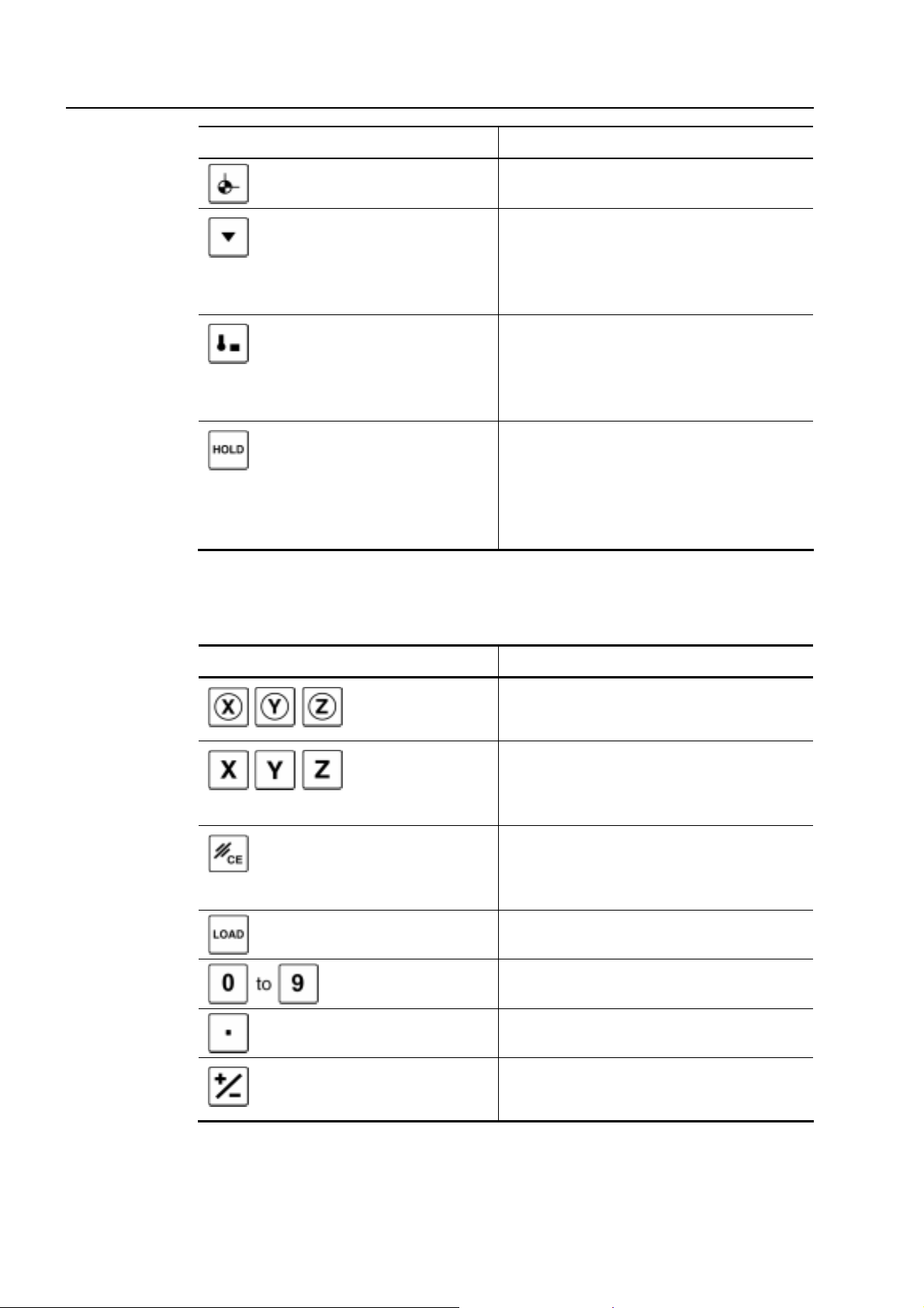
Symbol and name Function
Coordinate switch Switches the coordinate between 0 and 9.
Datum point set key Sets the function for datum point recall
using a scale reference point.
(Possible only when the AT100 series is
connected.)
Touch signal set key Sets the function for datum point setting
with the touch signal.
(Possible only when the AT100 series is
connected.)
Hold key Sets the function to hold the counter display
using the signal from the scale reference
point and touch signal probe.
(Possible only when the AT100 series is
connected.)
1.2.4 Name and function of keys for the lathe counter
The name and function of the function keys and ten-key are given below.
Symbol and name Function
Zero-set key Resets the displayed value of the s pecified
axis to zero.
Axis-designation
key
Cancel key • Cancels the number being entered.
Load key Loads the entered values.
Number keys Used to enter numbers 0 to 9.
Decimal-point key Sets the decimal point.
• Designates the axis to be set.
• Calls up the previous setting.
• Enables ten-key input.
• Cancels the operation being executed.
• Cancels the error.
1-6
Sign key Switches the entered number to negative or
positive.
No. 99MBE032A
1. INTRODUCTION
Symbol and name Function
ON/OFF switch Turns ON/OFF the display on the counter.
Display-unit switch key Switches the display unit.
If mm is selected, then the mm display
lights up.
Zero-approach key The target value is autom aticall y displa yed,
and sets the function to perf orm machining
until the displayed value is zeroed.
Bolt-hole circle key (available
with 2- and 3-axis counter)
Pitch machining key Not used.
1/2 key Halves the displayed value.
Tool number switching key Switches the tool number between 1 and 4.
Datum point set key Sets the function for datum point recall
T ool’ s machining coordinate
switching key
Hold key Sets the function to hold the counter display
Not used.
using scale reference point.
(Possible only when the AT100 series is
connected.)
Switches the tool’s machining coordinate
over ABS and INC.
using the signal from the scale reference
point and touch signal probe.
No. 99MBE032A
1-7
1.2.5 3-axis counter
1) Front panel of the main unit
2) Rear panel of the main unit
1-8
No. 99MBE032A
1 SETUP
2
2.1 Opening the Package
The package includes the following items.
KA counter 1
This chapter explains the procedures for setting up the KA counter.
Description of goods Quantity
NOTE
Power cord (1.8 m)
(2 m only for Australia-oriented specification)
Grounding wire (4 m) 1
Dust cover 1
User’s Manual 1
Warranty 1
After opening the package, check to make sure that the counter and standard
accessories are all there and that there are no nonconforming parts, and check that
nothing was damaged during shipment.
1
No. 99MBE032A
2-1
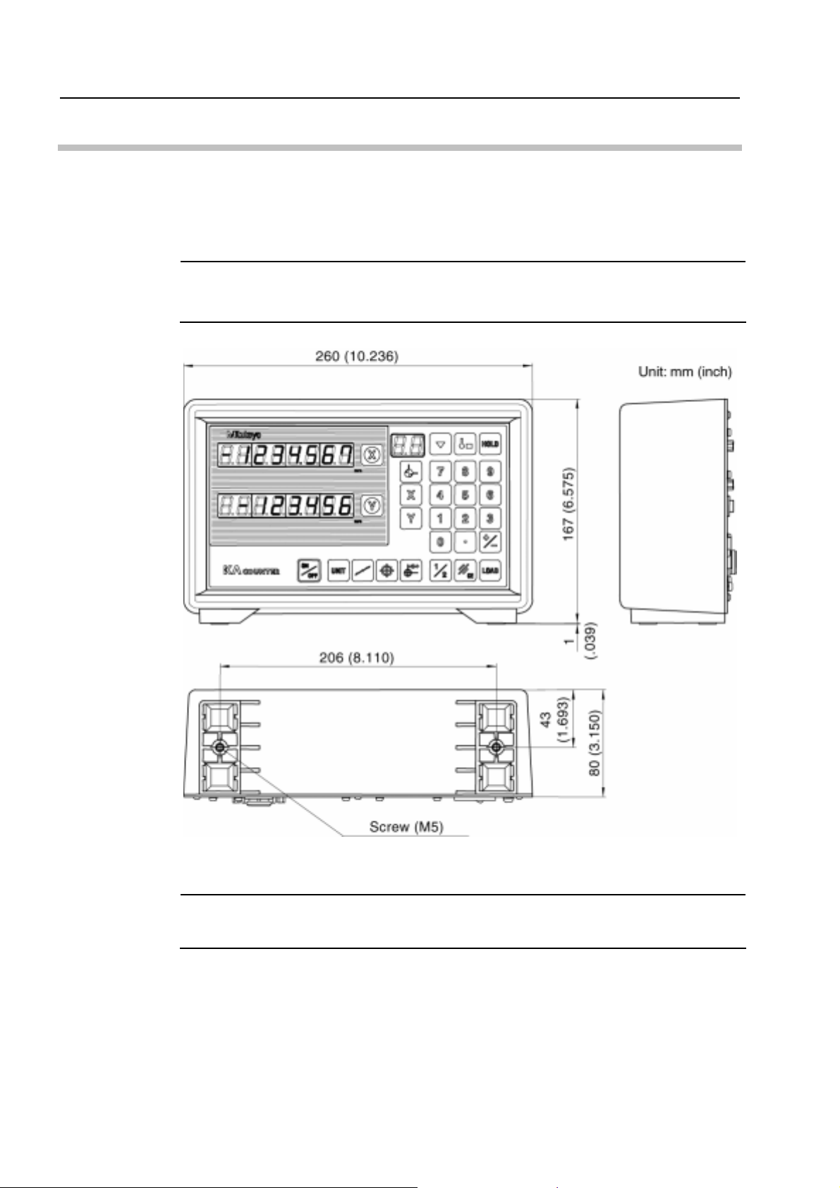
2.2 Installation
Use the M5 screw holes at the bottom of the counter for installing it to the counter stand or
the main unit of the machine tool.
The external dimens ions of the count er and the l ocati on of the scr ew holes f or installati on
are shown in the figure below.
NOTE
• There are no special installation fixtures supplied with this counter.
• External dimensions given below apply to 1-, 2-, and 3-axis counters.
2-2
NOTE
The fastening torque of screws ranges from 0.0015 to 0.002N • m (0.15 to 0.2kg • m).
Fastening with a torque exceeding this range may cause the counter case to be
damaged.
No. 99MBE032A
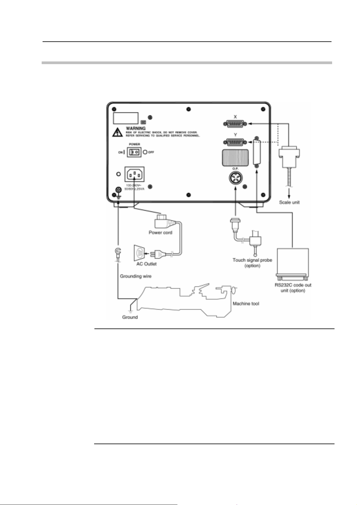
2.3 Connecting to the Counter
When connecting the power cord and external equipment to this counter, connect the
connectors to the rear panel as shown below. (Below diagram is applied for 2-axis
counter.)
2. SETUP
IMPORTANT
When connecting to external equipment, take note of the following items.
• Make sure the main power switch on the rear panel is off.
(This is not the display ON/OFF switch on the front panel.)
• Use the supplied power cord only.
• Connect this counter with the machine tool using the supplied grounding wire to avoid a
risk of electric shock.
• The power-supply line for this counter should be separate from that for the machine tool,
and if possible should be supplied from a dedicated outlet.
• Make sure the cables and external equipment are connected to the counter securely.
• If the Linear Scale is not connected to this counter, the least significant digit may flicker,
but this is not a malfunction.
• Since the scale m odel (AT100 series or AT700 series) is identified at a tim ing when the
main switch is turned to ON, always turn the main switch to ON with the desirable scale
being connected.
No. 99MBE032A
2-3

2-4
No. 99MBE032A
1 BASIC OPERATIONS
3
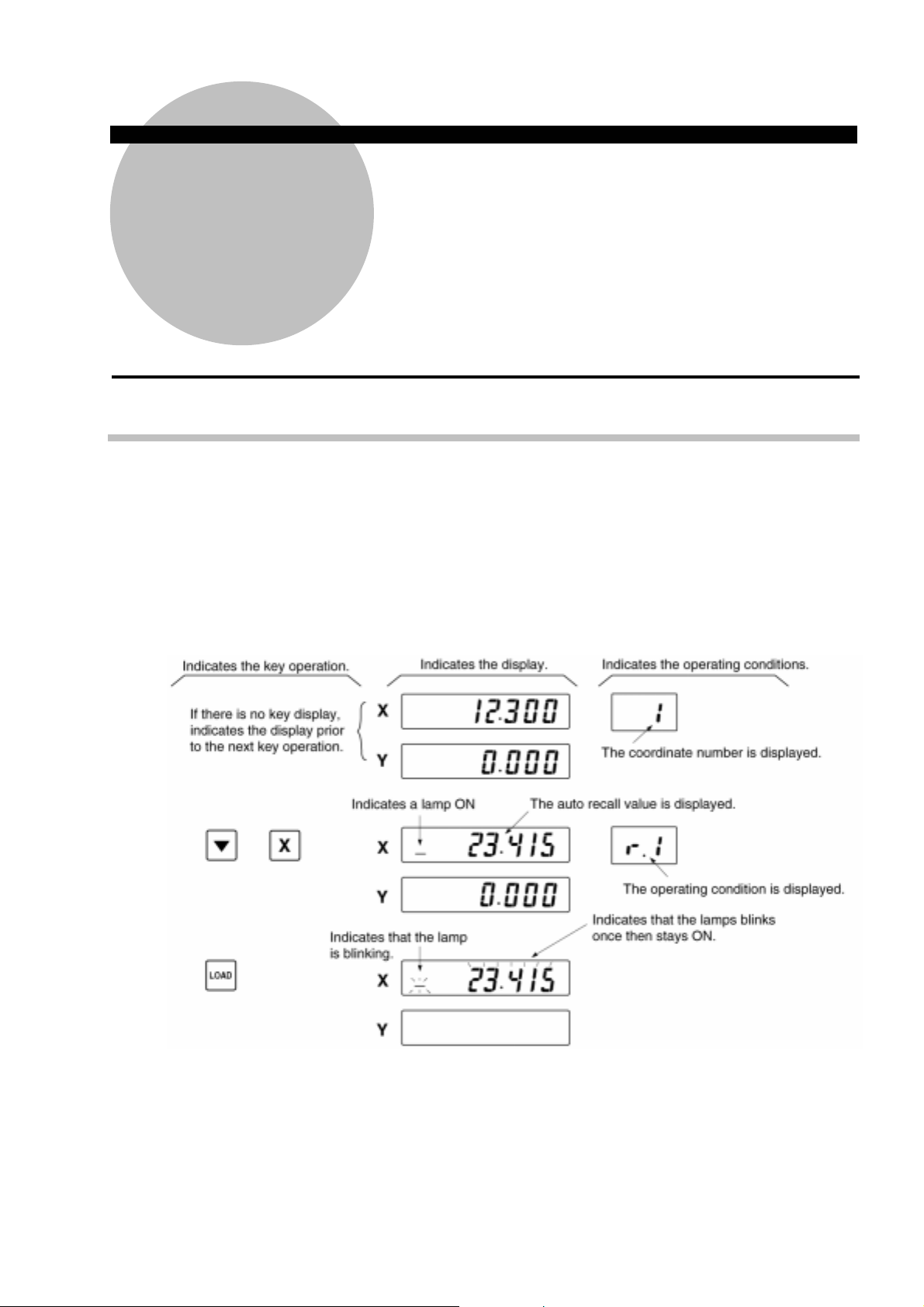
3.1 Explanatory Notes
The explanations of operations in this chapter are organized in such a manner as shown
below. Read this chapter with understanding of the way of explanation. Operation
procedures described in this manual are mainly based on the case of using the 2-axis
counter. Operation procedures unique to 1- or 3-axis counters are described when
necessary.
This chapter describes the basic operation of the KA counter.
Q Operation example display
No. 99MBE032A
3-1

3.2 Basic Operations in the Standard Counter
3.2.1 Turning ON/OFF the power
• Main power switch on the rear panel
The switch on the rear panel is
the main power switch. It turns
ON/OFF of the main power to
the counter.
• Display ON/OFF switch on the front panel
This is the switch to ON/OFF
the counter display. The display
will be on/off every time the
switch is pressed. If the main
power switch is on and this
switch is off, only the display
will be off, although the power
is supplied to the counting
circuits and the Linear Scales.
NOTE
• For normal operation after the power has been turned on the main power switch on the
rear panel should be left on, and the counter should be turned ON/OFF using the
display ON/OFF switch on the front panel.
• If the display is blinking after the power is turned on using the display ON/OFF switch,
this indicates that the displayed value is of no use. If this happens, cancel the value
using the Cancel key, then reset the machining datum point.
• Always operate the keys only with fingers. If a key is pressed with a sharp tip such as a
screwdriver, it may be damaged.
3-2
No. 99MBE032A
3. BASIC OPERATIONS
● Where AT100 series is connected:
1) Turning the power on
To turn the power on, turn on the main power switch on the rear panel.
If this is the first time since setting up the KA counter, the display will blink.
(This indicates that the displayed value is of no use.)
By pressing the Cancel key, the counter is ready to display a normal count value.
By referring to “3.2.3 Zero-set”, “3.2.4 Preset”, and “3.2.5 Saving and recalling a
datum point using the scale reference point”, set a machining datum point.
2) Turning the power off
NOTE
Use the display ON/FF switch on the front panel to turn the power off while remaining
the main power switch on the rear panel on.
By pressing the display ON/OFF switch, the display can be off.
3) Turning the power on again
Press the display ON/OFF switch on the front panel.
The display will be on.
• If there happened an abnormality in the power line, such as a power failure, the next
time the power is turned on using the display ON/OFF switch, the display will blink as
described in 1) above. If this happens, set the reference point for machining again.
• When the display is blinked even if parameter No. 15, described in Chapter 4, has been
set to “Save display”, this indicates that the displayed value is of no use. If this happens,
set the reference point for machining again.
No. 99MBE032A
3-3
● Where AT700 series is connected:
1) Turning the power on
To turn the power on, turn on the main power switch on the rear panel.
At this time, the display indicates the distance from the scale reference point.
By referring to “3.2.3 Zero-set”, “3.2.4 Preset”, and “3.2.6 Setting the machine origin
with the AT700 series”, set a machining datum point.
2) Turning the power off
Use the display ON/FF switch on the front panel to turn the power off while remaining
the main power switch on the rear panel on.
By pressing the display ON/OFF switch, the display can be off.
3) Turning the power on again
Press the display ON/OFF switch on the front panel.
The display will be on.
3.2.2 Counting and displaying
This section is for the user who is using the KA counter with a minimum resolution of
0.0005 or 0.0001mm (0.5 or 0.1µm).
The user who is using it with a minimum resolution of 0.005 or 0.001mm (5 or 1µm) may
skip this section.
• In order to expand the display range of the KA counter, the counting range in the +
count direction and the - count direction are different.
The counting range when the KA counter is used with the minimum resolution of
0.0005 or 0.0001mm (0.5 or 0.1µm) is as follows:
+9999.9999 to -999.999 (approximately +10m to -1m)
3-4
No. 99MBE032A
3.2.3 Switching the coordinate
Moves from the current Coordinate to the specified coordinate.
• Moves from the current Coordinate 3 to Coordinate 5.
KA counter coordinate
Coordinate No. Function
0 A coordinate system that displays coordinate values from the machine
origin. It does not allow zero-setting and presetting. To use this
function, perform either of “3.2.5 Saving and recalling a datum point
using the scale reference point” or “3.2.6 Setting the machine origin
with the AT700 series”.
3. BASIC OPERATIONS
1 to 9 A coordinate system used for performing usual machining operation.
3.2.4 Zero-set
Resets the display value for each axis to zero.
• Resets the X-axis value to zero.
* Zero-adjustment cannot be performed at coordinate 0.
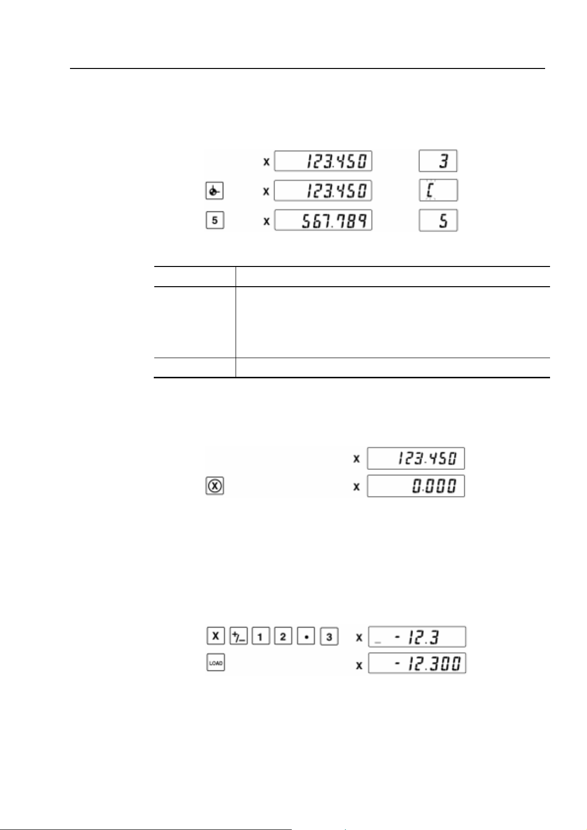
3.2.5 Preset
Set an arbitrary value onto the arbitrary axis through the key entry. Preset values can be
saved in memory for each coordinate so that they can be retrieved even after the system
power is reset.
• Preset -12.3 for the X-axis.
No. 99MBE032A
3-5

• Call up the value preset to preset it as is for the X-axis.
• Canceling the key input before loading the preset value.
If the Load key has not yet been pressed, it is possible to cancel all of the input
numbers by pressing the Cancel key. After the numbers have been canceled, the
display returns to the value before key input. If the Load key has already been pressed,
use the preset operation again to set the correct value.
IMPORTANT
• Preset data stored in the KA counter is the data input by the most recent preset
operation.
• The preset data stored in the KA counter has been saved on the basis of coordinate
systems described later.
• If data is preset through operation of the touch signal probe or zero-approach function
(described later), the preset data stored in the KA counter will be changed to those
values.
• Do not displace any axis scale during numeric entry. If displaced during entry for
presetting, etc., the scale unit may be damaged due to an overrun.
• Even if the counter exceeds the counting range, Error 30 will not be displayed during
numeric entry. The error message will be displayed after numeric entry has been
completed.
• Do not displace any axis scale too much while presetting is being performed.
• Zero-adjustment cannot be performed at Coordinate 0.
3-6
No. 99MBE032A
3. BASIC OPERATIONS
NOTE
If the following operations 1 and 2 are repeated at the occurrence of an overflow when
using the AT100 series linear scale, an overflow error (Error30) may occur even if a value
smaller than the maximum preset value shown below is preset.
If presetting a large value and error occurrence are repeated multiple times, the
above-mentioned situation will be encountered due to overflow of offsetting in the
counter. If this is the case, perform offset correction procedure described below for the
axis where Error30 has occurred, then the normal state will be restored.
Exercise care when presetting a large value exceeding the maximum preset value.
• Operation at the occurrence of an overflow
1. Preset a value (larger than the maximum preset value).
2. An error occurs. (E.g. Error20)
3. Repeat steps 1 and 2.
• Maximum preset value
Resolution Maximum preset value
0.01/0.05 mm
0.001/0.005 inch
0.001/0.005 mm
0.0001/0.0005 inch
+500000.00 (500 m)
+200000.00 inch
+50000.000 (50 m)
+2000.0000 inch
0.0001/0.0005 mm
0.00001/0.00005 inch
• Overflow correction procedure
a. Press the [▼], [SET], [X] (or [Y] or [Z]), [0], and [LOAD] keys in this order.
b. Move the linear scale to pass through the origin mark.
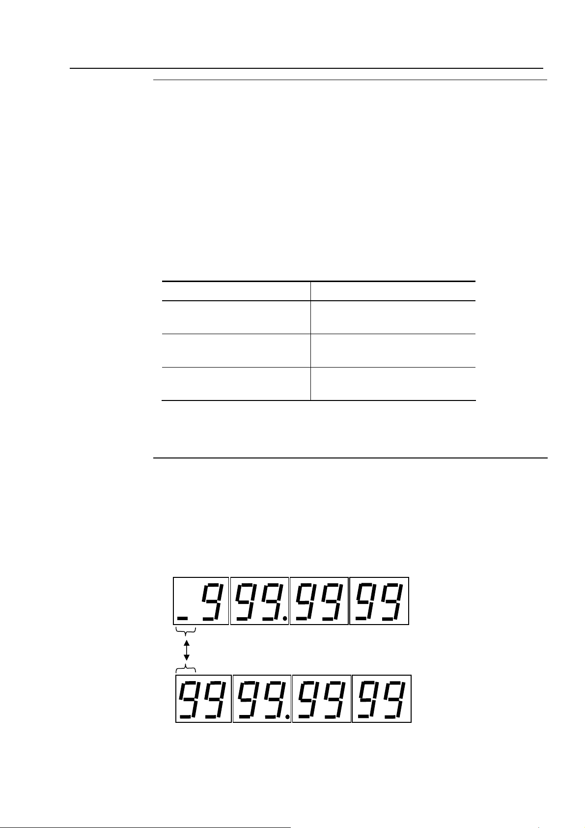
For the user who is using the KA counter with a minimum resolution of 0.0005 or
0.0001mm.
When data to be preset is smaller than or equal to 1m, the display method of the most
significant digit and the sign differ from the normal preset. It alternately displays the sign
and the most significant digit as shown in the figure below.
• Example) +9999.9999
+5000.0000 (5 m)
+200.00000 inch
Alternately displays a cursor and a numeric.
No. 99MBE032A
3-7

3.2.6 Saving and recalling a datum point using the scale reference point
(when the AT100 series is connected.)
Where the AT700 series is connected, refer to “3.2.6 Setting the machine origin with the
AT700 series”.
1) Saving the scale reference point
This operation saves the dimension between an appropriate reference point of the
Linear Scale and the datum point of the workpiece being machined, in the KA counter
as “origin data”. When the scale reference point is detected, the display is held for two
seconds, and this value is saved in the counter as “origin data”. The saved origin data
is not lost when the power is turned off, so it is possible to easily recall the machining
datum point on the workpiece being machined using the scale reference point recall
operation described in 2).
NOTE
Immediately after the power has been turned on, if the scale reference point recall
operation is performed at the beginning of work, as described in 2) below, it is not
necessary to perform this datum point recall operation.
• Saving the machining datum point in the X-axis direction using the scale reference
point.
Step 1 Use the keys so that the displayed value can be held when the scale reference
point is detected.
Step 2 Move the machine table in the direction of detecting the scale reference point.
When the scale reference point is detected, the displayed value is held, and a
buzzer sounds for two seconds. This display value (L) at this time is the
dimension to the scale reference point from the machining datum point, and is
automatically saved in the KA counter as “origin data”.
3-8
No. 99MBE032A

3. BASIC OPERATIONS
After the buzzer sounds off, the counter automatically returns to normal counting.
IMPORTANT
• When detecting the scale reference point move the worktable at a traveling speed of
50mm/s or less. If the worktable is moved faster than 50mm/s, the measuring error will
increase.
• When saving the scale reference point, be sure to remember the following two points. In
order to recall the machining datum point, the same scale reference point that was
saved must be used.
1. Which coordinate system, ABS or INC, was used?
2. The position of the machine table for both the X- and Y-axis when the buzzer
sounded.
• After saving the scale reference point, if an operation is performed which translates the
origin of the coordinate system such as zero-set or preset, the origin data is also
automatically offset corresponding to the translation.
• Perform scale reference point save and recall operation for the X- and Y-axis separately.
• Do not displace any axis scale during numeric entry. If displaced during entry for
presetting, etc., the scale unit may be damaged due to an overrun.
• Even if the counter exceeds the counting range, Error 30 will not be displayed during
numeric entry. The error message will be displayed after numeric entry has been
completed.
• Do not displace any axis scale too much while presetting is being performed.
2) Recalling the scale reference point
With this operation, the machining datum point at the time the power was turned off is
recalled from the origin data saved in the KA counter.
IMPORTANT
• This operation should be performed for the coordinate (1 to 9) for which the scale
reference point was saved. If scale reference point recall operation is performed for one
coordinate, the machining datum point for the remaining coordinates will also be
recalled automatically.
• The scale reference point should be recalled at the beginning of work just after the
power has been turned on.
• Recalling the machining datum point from the scale reference point in X-axis direction.
Step 1 Call up the saved origin data, and after detecting the scale reference point,
perform the key operation to start counting.
No. 99MBE032A
3-9

If the axis was specified in the scale reference point recall operation, the saved origin
TIP
data will be called up, however it is possible to key in a different value using the ten-key
pad.
Step 2 Move the machine table and detect the same scale reference point that was
saved by the scale reference point save operation. At the instant the reference
point is detected, the KA counter starts counting. The machining datum point is
recalled.
IMPORTANT
NOTE
The scale reference point is set at 50mm intervals along the Linear Scale, so find the
scale reference point that was saved by the save operation.
If datum setting and machining is performed without having recalled the scale reference
point prior to work, and if it is necessary that the machining datum point be saved for
future work, save the scale reference point as described in 1) above, then turn off the
display ON/OFF switch.
• About the machine origin (Coordinate 0 is used.)
The user is allowed to set specifically for each machine a reference point (machine
origin) that will not be affected by the normal operation including zero-point setting.
(1) Setting the machine origin data
Obtain the machine origin data (offset value) with the following procedure, then set
it to Parameter 33.
1. On Coordinate 1, zero-set at the position of the machine origin.
2. Perform the scale origin memorizing operation.
3-10
3. If the axis designation key is pressed following the having been pressed
in 2) Recalling the scale reference point, the origin data (offset value) will be
displayed.
Take a note of this value and set it to Parameter 33.
For the setting method refer to Chapter 4, Parameters.
(2) Recalling the machine origin
On Coordinate 0, perform the above described “2) Recalling the scale reference
point”.
No. 99MBE032A

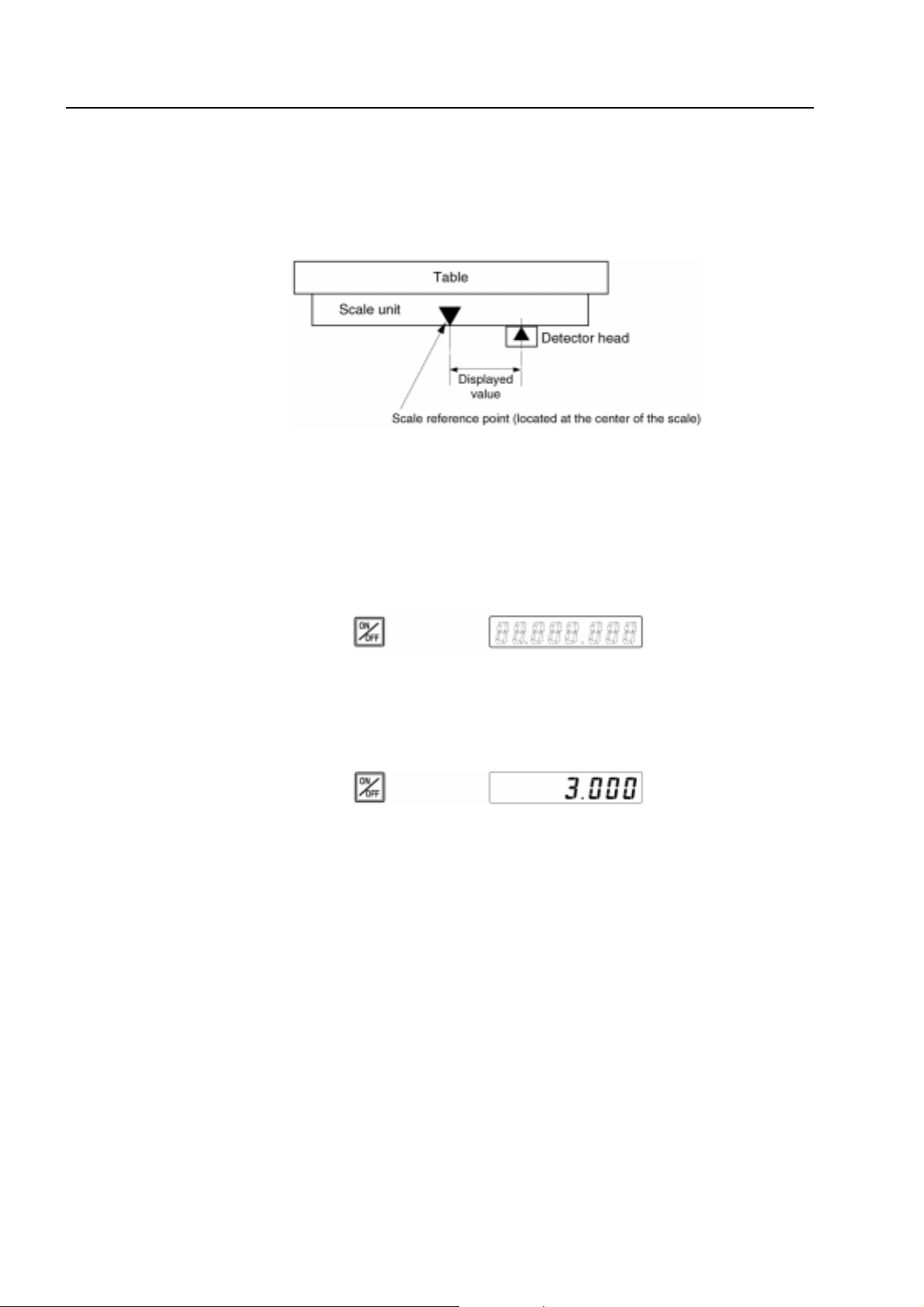
3.2.7 Setting the machine origin using the AT700 series
With the AT700 series if the machine origin is once determined, that reference point
cannot only be maintained through the subsequent normal operations such as zero setting,
etc., but also be protected from being lost even when the power is off.
Use the following procedure to set the machine origin offset value to Parameter 33.
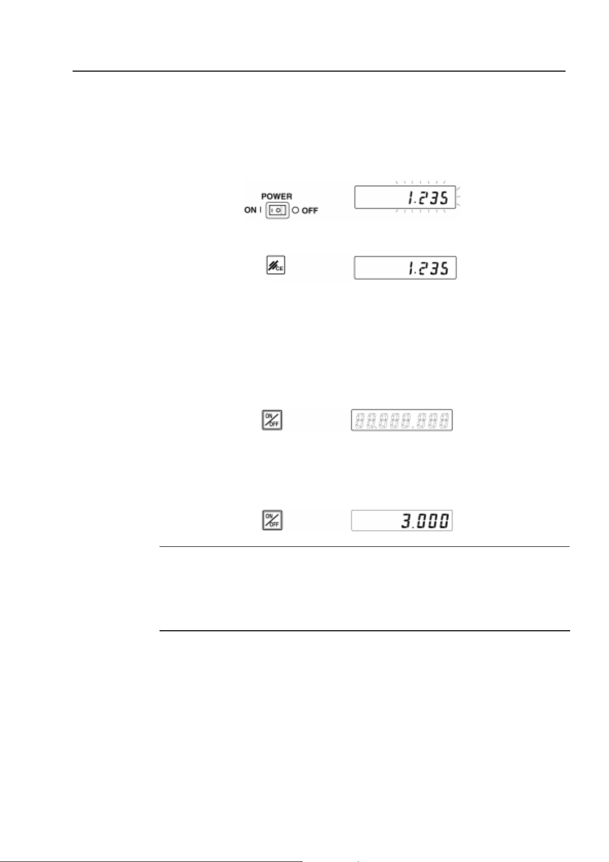
(1) Make sure that Parameter 33 is 0.000.
1. While pressing the key turn the main switch on the rear panel to ON.
2. Make sure that the display looks like the following.
3. BASIC OPERATIONS
3. Enter Parameter 33.
4. Make sure that the display shows 0.000, then turn the main switch on the rear panel
to OFF.
(2) Measure the machine origin offset value.
1. Turn on the counter power and display Coordinate 0.
No. 99MBE032A
3-11

2. Feed the table to align with the machine origin.
3. Record the displayed value.
(3) Enter the machine origin offset value.
1. Turn off the power.
2. Substitute the machine origin offset value in Parameter 33.
In this substitution, note that the sign of the value recorded in above 3. of (2) must
be reversed.
+
3-12
No. 99MBE032A

3. BASIC OPERATIONS
3.2.8 Datum setting, centering and measuring with the touch signal probe
(Possible only when the AT100 series is connected.)
1) Datum setting with the touch signal probe
The KA counter can be connected to a touch signal probe (optional), and it is possible
to set the datum point for a workpiece.
• Setting up the datum point in the X-axis direction of the workpiece.
Step 1 Preset the radius of the ball tip of the touch signal probe in the X-axis of the
counter as shown below. With this setup, when the touch signal probe comes in
contact with the surface of the workpiece, the counter starts counting from the
value of the radius of the ball tip.
In the following explanation, the probe ball tip diameter is set to φ10mm and the
center of the ball is on the minus count side of the datum surface to be
determined. Because of this a minus sign is given to the preset value.
IMPORTANT
For datum setting with the touch signal probe, the radius of the ball tip must be preset in
the counter for offsetting. The sign (+/-) for this offset value depends on the count
direction in which the machine moves.
Step 2 Bring the touch signal probe into contact with the reference surface of the
workpiece. This will set the datum point for machining.
A buzzer will sound when the probe is brought into contact with the workpiece,
and counting will start.
No. 99MBE032A
2) Centering with the touch signal probe
It is possible to perform centering of the workpiece with a touch signal probe (optional)
connected to the counter.
3-13

• Determine the center in the X-axis direction of the workpiece
Step 1 Set up using keys so that the counter starts counting from zero in the X-axis at
the time the touch signal probe comes into contact with the reference surface of
the workpiece. (For centering, it is not necessary to correct for the radius of the
probe ball tip.)
Step 2 After setting us a function of holding the display move the touch signal probe to
the opposite end, and bring it into contact. The displayed value at this time is the
dimension of the workpiece, including the ball tip diameter of the probe. If this
value is halved, the center point of the measured dimension is displayed.
3-14
No. 99MBE032A

3. BASIC OPERATIONS
Step 3 With the Cancel key, release the Hold mode of the display, and move the
machine table so the counter reads zero. Centering is now complete.
IMPORTANT
• Leave an interval of at least one second from the time the touch signal probe comes in
contact with the workpiece until the next contact. If the interval is less than one second,
it may be impossible for the counter to detect the measurement point.
• Do not displace any axis scale during numeric entry. If displaced during entry for
presetting, etc., the scale unit may be damaged due to an overrun.
• Even if the counter exceeds the counting range, Error 30 will not be displayed during
numeric entry. The error message will be displayed after numeric entry has been
completed.
• Do not displace any axis scale too much while presetting is being performed.
3) Measuring with the touch signal probe
The KA counter can be connected to a touch signal probe (optional) and can measure
the dimensions of the workpiece.
The display value is held while the touch signal probe is in contact with the workpiece.
This operation can be performed repeatedly until quitting the touch signal probe
measurement function. Press the Cancel key to quit.
• Measuring the dimensions of the workpiece in the X-axis direction
Step 1 In order to subtract the diameter of the ball tip of the touch signal probe from the
measured value, perform key operation to start counting from that value.
In the example below, the diameter of the ball tip of the touch signal probe is
taken to be 10mm.
IMPORTANT
No. 99MBE032A
The touch signal probe comes in contact with both ends of the workpiece, so preset the
KA counter to correct for the diameter of the probe ball tip. The sign of the corrected
value should be negative when measuring the outside diameter, and positive when
measuring the inside diameter.
Step 2 Bring the touch signal probe in contact with reference surface of the workpiece.
A buzzer sounds during contact, and when it is removed counting starts.
3-15

Step 3 Before the touch signal probe is in contact with the measured surface on the
other side, set up the Hold mode using the key.
Step 4 Bring the touch signal probe in contact with the opposite end. The held display
value is the dimension of the workpiece.
Step 5 Quit the touch signal probe measurement function.
IMPORTANT
• When measuring with the touch signal probe move the worktable at a traveling speed of
50mm/s or less. If the worktable is moved faster than 50mm/s, the measuring error will
increase.
• Leave an interval of at least one second from the time the touch signal probe comes in
contact with the workpiece until the next contact. If the interval is less than one second,
it may be impossible for the counter to detect the measurement point.
• Do not displace any axis scale during numeric entry. If displaced during entry for
presetting, etc., the scale unit may be damaged due to an overrun.
• Even if the counter exceeds the counting range, Error 30 will not be displayed during
numeric entry. The error message will be displayed after numeric entry has been
completed.
• Do not displace any axis scale too much while presetting is being performed.
3.2.9 Halving the display
The KA counter is capable of halving the display value or preset value and displaying the
halved value.
1) Halve the display value for the X-axis.
• Halve the currently displayed value, 123.000.
3-16
No. 99MBE032A

2) Halve the preset value for the X-axis.
• Halve the preset value, 469.000.
3. BASIC OPERATIONS
IMPORTANT
• The value displayed at the time of the axis designation during the preset operation is the
previous preset data.
• The data entered with this operation is saved in the counter as preset data.
3.2.10 Bolt-hole circle machining
This function is available exclusively with both 2- and 3-axis counters. (In case of using
3-axis counter, this function is available with X- and Y-axis settings.)
The bolt-hole circle machining function is used to perform bolt-hole circle machining.
By setting the center position, diameter, number of divisions and offset angle of the circle,
the bolt-hole circle machining function calculates the positions around the circumference
for boring holes, and displays the target coordinate value for each machining point.
When boring a hole, displace the machine table to the position so the display becomes
zero. The position of the tip of the cutting tool at the time of data setting is taken as the
center for the circle to be calculated. The position for boring the first hole is the point offset
by the offset angle (Ang) in the positive direction of the X-axis (see the figure below), and
the location of the holes to be bored successively at equal interval is determined along the
circumference of the circle having the diameter (d) and divided by the number of divisions
(n).
No. 99MBE032A
3-17

IMPORTANT
The input range for the setting items are as follows:
Setting item Input range
Diameter ± 9999.999mm or ± 999.9999”
Number of divisions 2 to 360 divisions
Offset angle 0 to 359.9 degrees (unit: 0.1 degree)
• When using the bolt-hole circle machining function, the resolution for the X- and Y-axis
should be the same.
• If an error occurs in the KA counter, press the Cancel key to quit the bolt-hole circle
mode.
• After the bolt-hole circle machining is complete, the coordinate system returns to that of
the mode prior to the bolt-hole circle mode.
• Do not displace any axis scale during numeric entry. If displaced during entry for
presetting, etc., the scale unit may be damaged by an overrun.
• Even if the counter exceeds the counting range, Error 30 will not be displayed during
numeric entry. The error message will be displayed after numeric entry has been
completed.
• Do not displace any axis scale too much while numeric entry is being performed.
• When in inch mode, due to the setting of the counter, there may be cases where the
input range shall be ± 99.99999”.
• Performing the bolt-hole circle machining
Step 1 Position the tip of the drill at the center of the circle on the workpiece.
Step 2 Press the bolt-hole circle key. The diameter and the number of divisions are
recalled on the X-axis and Y-axis, respectively (already input values).
Step 3 While the “d” at the left end of the display is blinking, enter the diameter using the
ten-key and press the Load key. If using an auto-recalled value, only press the
Load key.
3-18
No. 99MBE032A

3. BASIC OPERATIONS
Step 4 While the “n” at the left end of the display is blinking, enter the number of
divisions using the ten-key and press the Load key. If an auto-recalled value is
used, only press the Load key. The KA counter display becomes ready for input
of the offset angle.
Step 5 While the “Ang” at the left end of the display is blinking, enter the offset angle
using the ten-key and press the Load key. If an auto-recalled value is used, only
press the Load key. After this value is entered, the setting complete code (000)
followed by the number of divisions is displayed for two seconds.
Step 6 Press the Load key and call up the first target value, and execute the bolt-hole
circle machining at the specified location.
No. 99MBE032A
3-19

Step 7 After the hole has been made, press the Load key and call up the target value for
the next hole, then move the machine table and drill the next hole. Each time the
Load key is pressed, the target value is updated, so repeat the same procedure.
Step 8 After machining the holes according to the set number of divisions, the counter
returns to the display of the target value of the first hole.
If machining is complete, or to abort machining, press the Cancel key and quit
the bolt-hole circle machining function.
NOTE
• The input settings are not lost even when the power is turned off. Those setting data is
called up automatically (auto recall) and can be used if desired.
• When the bolt-hole circle machining function ends, the coordinate system used before
the start of the function is returned.
3-20
No. 99MBE032A

3.2.11 Pitch machining
This is the mode in which a certain interval between two points on the X-Y plane can be
machined at even spaces.
For this pitch machining the errors produced from positioning the table can be
automatically corrected.
Setup items and their ranges are shown below:
Setup item Input range
X-axis start point ± 9999.999 mm
Y-axis start point ± 9999.999 mm
X-axis end point ± 9999.999 mm
Y-axis end point ± 9999.999 mm
Number of divisions 999
3. BASIC OPERATIONS
• Operate with the following procedures.
Step 1 Press the Pitch Machining key.
Step 2 Enter the X coordinate of the start point.
Blinking of the X-axis cursor shows its time to enter the X coordinate of the end
point.
No. 99MBE032A
3-21

Step 3 Enter the Y coordinate of the start point.
Step 4 Enter the X coordinate of the end point.
Use the auto-recall value without modifying it.
Step 5 Enter the Y coordinate of the end point.
Use the auto-recall value without modifying it.
Step 6 Enter the number of divisions.
The maximum number of divisions is 999.
Step 7 Perform the machining.
000 implies the completion of setting, while 010 shows implies the number of
divisions.
3-22
In two seconds the display will change to the following, showing that the pitch
machining is ready.
Now it is ready to perform the pitch machining.
Recall the first target point.
No. 99MBE032A

3. BASIC OPERATIONS
Feed the table so that the display shows 0.000.
Even when a machining error is produced, it will never be accumulated because
the error correction to the next target is automatically undertaken.
Continue the machining while recalling the target values successively by
pressing the LOAD key.
Step 8 If the set numbers of the pitch machining is completed, the counter returns to the
display of the first target value.
If the machining is complete, or to abort machining, press the Cancel key and
quit the pitch machining function.
NOTE
• The entered setup item data will not be lost even after the power is off. Each piece of
data can be saved in memory as the independent setup data for each coordinate. At the
next input of the setup data they will be automatically recalled (auto-recall).
• When the pitch machining function is terminated, the table will be restored to the
coordinate existed before the pitch machining function began.
• Pitch machining data will be saved in memory for each coordinate.
No. 99MBE032A
3-23

3.2.12 Zero approach machining
If this function is used in the drilling process, the given pitch of the hole is entered in the
counter and the target value from the current position to the hole is automatically displayed.
The machine table is fed until the displayed value becomes zero, and the hole is drilled. By
repeating this procedure, holes can be drilled efficiently.
NOTE
Errors involved in positioning the machine table are automatically corrected for the
target value of the next hole.
An example of drilling
• Drilling the above holes using zero approach
Step 1 Press the Zero-approach key.
Step 2 Feed the machine table to the datum point, and set the counter display to zero.
Step 3 Enter the distance (10mm) for the first drilling point.
Step 4 Feed the machine table to the machining position, where the counter displays
-0.010mm, and drill a hole.
3-24
No. 99MBE032A

3. BASIC OPERATIONS
Step 5 Enter 12mm, the distance to the next machining point.
The KA counter corrects the previous positioning error, -0.010mm and displays
the actual distance the machine needs to move to reach the next machining
point.
Step 6 To quit the zero-approach machining function, press the Cancel key.
IMPORTANT
NOTE
• Do not displace any axis scale during numeric entry. If displaced during entry for
presetting, etc., the scale unit may be damaged due to an overrun.
• Even if the counter exceeds the counting range, Error 30 will not be displayed during
numeric entry. The error message will be displayed after numeric entry has been
completed.
• Do not displace any axis scale too much while numeric entry is being performed.
• It is possible to zero-set the counter during the zero-approach mode. However, if the
counter is zero-set, the accumulated error up to that point cannot be corrected.
• If the zero-approach mode is canceled, the display restores the state in which
zero-approach was selected.
• When the zero-approach mode is entered, the counter value remains unchanged.
• The zero-approach data can be set for each coordinate, however, note that it is shared
also as the preset data.
3.2.13 Changing the unit of measurement
It is possible to switch the unit of measurement between mm and inch (1/25.4).
NOTE
The indicator “mm” on the front panel turns on if mm is selected. The indicator turns off if
inch (1/25.4) is selected.
No. 99MBE032A
NOTE
• Changing the unit of measurement
When the display ON/OFF switch is turned on, the unit set when the switch was turned
off is selected.
For the accuracy of conversion between mm and inch counts, refer to the table in page
4-5.
3-25

3.2.14 Addition mode
This function applies only to the 3-axis counter.
By setting parameter 43, the KA counter will display the summed value of the Y- and
Z-axis display values on the Y-axis display. (For information about parameter setup, refer
to the appropriate parameter section.)
An example of using the addition mode
This mode is used if the feed table consists of two stages.
If the addition mode has been set, “o” is displayed in the position of the most significant
digit of the Z-axis display. Other digits on the Z-axis display are unlit.
3-26
No. 99MBE032A

3. BASIC OPERATIONS
- Restrictions when the addition mode is set Origin and touch signal setup operations
If the addition mode is selected, the touch signal SET/HOLD and origin SET/HOLD
functions on the Y- and Z-axis cannot be used.
Example No. 1
▼
[ Y ] The buzzer sounds twice.
Example No. 2
[TSP]
[HOLD]
[Z] The buzzer sounds twice.
The X-axis touch signal HOLD function can be used.
Presetting
• The presetting operation for only the Z-axis cannot be performed. The buzzer sounds
twice if the Z-axis designation key is pressed.
• If the Y-axis presetting operation is performed, a preset value will be stored for the
Y-axis where the summed value (Y + Z) is displayed.
Zero-setting
• The zero-setting operation for the Z-axis cannot be performed. The buzzer sounds
twice if the Z-axis zero-set key is pressed.
• If the Y-axis zero-setting operation is performed, the summed value (Y + Z) displayed
on the Y-axis display will be zero-set.
Zero approach machining
• Zero approach data cannot be set for the Z-axis.
• If Y-axis zero approach data is entered, zero approach calculation will be performed
for the Y-axis where the summed value (Y + Z) is displayed.
Bolt-hole circle machining
• The bolt-hole circle machining function cannot be used in the addition mode. The
buzzer sounds twice if the Bolt-hole circle key is pressed.
No. 99MBE032A
Display-halving (1/2) function
• The display-halving (1/2) function cannot be performed for the Z-axis.
• If the Y-axis display-halving (1/2) operation is performed, display-halving calculation
will be performed for the Y-axis where the summed value (Y + Z) is displayed.
3-27

3.3 Outline of the Lathe Counter
3.3.1 Setting parameters for the lathe counter
When this counter is used as the lathe counter, it is required to modify the initial values of
parameters. For detail refer to “4.3.4 Setting parameters for the lathe counter”.
Also for the method of turning on and off the power, refer to “3.2.1 Turning ON/OFF the
power”.
3.3.2 Lathe counter operation modes
The lathe counter operation modes in the KA counter are as illustrated below.
3-28
No. 99MBE032A

3. BASIC OPERATIONS
• Explanation of each operation mode is as mentioned below.
No. Item Description
0 Power OFF The main power is turned off.
3 Count mode
4 Display OFF mode
5 Parameter mode Parameters are input in this mode.
6 Origin recall Recalls the scale origin.
7 Origin storage Stores the scale origin.
8 Zero approach mode
9 Tool number switching Switches to the number of the tool to be used.
10 Tool offsetting A compensation value for a tool length is set in this mode.
IMPORTANT
Before proceeding to the machining in 3: Count mode, it is necessary to perform 10:
Tool offsetting.
3.3.3 Configuration of coordinates
Coordinates of the KA counter have the following configuration:
Counter basic mode in which machining operation is
performed.
Entered from the count mode with the [ON/OFF] key.
Counting is still performed.
By inputting a desired size, zero approach
machining that is to perform machining to approach
the display value to zero is performed.
approach buzzer is available.
The zero
1 2 3 4
ABS
INC
3.3.4 Setup for tool offset
The KA counter is provided with the function for compensating the difference in each tool
length and displaying always the center of a workpiece (ABS coordinate) or the depth of
cut (INC coordinate) with respect to the tool tip. To use this function, the counter needs to
store the lengths of each tool to be used. The setting up of these lengths in the counter is
called tool-offset setup. The tool offset is set in the too offset setup mode.
This section explains the procedure for setting tool offset values.
The following figure shows a state in which some tools are set on a lathe.
Four tools are attached to the tool post and each tool is assigned a tool number as shown
in the figure.
Trial machining is performed using the tools sequentially, the dimensions of a workpiece
are measured with a caliper or a micrometer, and then those values are entered in the
counter.
○ ○ ○ ○
○ ○ ○ ○
No. 99MBE032A
3-29

Step 1 Check that the counter is set to the ABS coordinate in the count mode. If it is not
NOTE
set to the ABS coordinate, press the key to switch to the ABS coordinate.
After confirming the display, press the key twice.
“t” on the sub-display blinks to indicate that the counter is in the tool offset setup
mode.
If the current coordinate is the ABS coordinate, the decimal point in the sub-display is
illuminating.
For more information about the ABS coordinate, refer to “3.3.8 A/I coordinate switch”.
Step 2 To change the tool number, press a numeric key corresponding to the tool
number assigned to the tool used. Specify the tool number 1 by pressing the 1
key. The tool number 1 will be displayed.
(Press twice)
3-30
No. 99MBE032A

3. BASIC OPERATIONS
Step 3 Perform trial machining using the tool number 1. After moving the tool aside,
measure the diameter of a workpiece with a caliper or a micrometer, then preset
the measured value. Here, set 50.000 as the measured value. This completes
the tool offset of tool number 1.
Step 4 Switch the offset tool number to 2.
Press the 2 key to select tool number 2. Tool number 2 will be displayed.
Step 5 Perform trial machining using the tool number 2. After moving the tool aside,
measure the diameter of the workpiece with the caliper or the micrometer, then
preset the measured value. Here, set 45.263 as the measured value.
Step 6 From this point, repeat the tool presetting procedure for the necessary tools.
Press the key or the Cancel key to quit the tool offset mode.
NOTE
If a tool wears from machining, the counter display may deviate. If this is the case, set
up the tool offset again only for the worn tool.
If tool offset setup has been completed, the counter will display correct values.
3.3.5 Count mode
After the tool offset value is set or the coordinate is restored, the KA counter does display
the correct values. This allows you to perform the machining easily.
Before commencing your machining note the following points for improving the efficiency
of operation.
NOTE
• There are two coordinate displays; ABS coordinate and INC coordinate. The ABS
coordinate shows the diameter of a workpiece using the center of the workpiece as the
reference point. The reference point of the INC coordinate can be optionally translated.
In general, the INC coordinate is used to display the cutting depth based on the result of
zero-setting on the workpiece surface.
No. 99MBE032A
• Choose the tool number that corresponds to the actually used tool. Machining with a
wrong tool number will result in an inaccurate machining.
3-31

3.3.6 Zero-setting/Presetting
The KA counter appends convenient capabilities to the zero-set and preset functions to
facilitate lathe-machining operation.
Zero-setting or presetting in the KA counter is
performed not only for the currently displayed
value, but also for the display values of other
tools. Each reference point is parallel
translated. If the tool No. 1 tip is on the
workpiece surface as shown in the figure, the
reference point of tool No. 1 is translated to
the workpiece surface and the counter
display becomes 0.000 when zero-setting is
performed. At the same time the reference
points of other tools are also translated to this
position.
Since the reference points of all tools are
calculated into the same point, the operator
can concentrate on machining without being
aware of the tool length difference.
TIP
If zero-setting and presetting are repeated some times for all tools after setting the
X-axis resolution to 0.002mm, the display values may be indicated as if they had a
dispersion of 0.002mm (actual length: 0.001mm). This is because the counter counts as
precisely as possible and rounds off the display value. The counter will operate properly
since it is not a malfunction.
3.3.7 Tool number switch
The tool number can be changed from 1 to 2 by observing the following procedure.
3-32
No. 99MBE032A

3.3.8 A/I coordinate system switch
The KA counter has two kinds of coordinate systems: Absolute (ABS) coordinate system,
and Incremental (INC) coordinate system.
• Change the coordinate system currently used.
The coordinate system changes in the following order:
ABS coordinate system INC coordinate system ABS coordinate system
3. BASIC OPERATIONS
Illumination of the dot (.) in the sub-display shows they are ABS coordinates.
No. 99MBE032A
3-33

NOTE
1. Features of ABS and INC coordinates on the X-axis
• The reference point in the ABS coordinate is designated as the center of a
workpiece. Therefore, the display value in the ABS coordinate indicates the diameter
of the workpiece.
• In the INC coordinate zero-setting and presetting can be performed at an arbitrary
position. For example, this function allows the real-time depth of cut to be displayed
by zero-setting on a workpiece surface.
Coordinate features
ABS coordinate Center of a workpiece Disabled Diameter
INC coordinate Arbitrary position on a
Appropriate use of two coordinates
Reference point of
coordinate (0 point)
workpiece
Zero-setting/presetting Display
content
Enabled Depth of cut
2. Features of ABS and INC coordinates on the Y- and Z-axis
Although there is no functional difference between the ABS and INC coordinates on
each axis, it is recommended to use the coordinate separately as shown in the figure
below.
3-34
No. 99MBE032A

3.3.9 Halving the display
The KA counter is capable of halving the display value or preset value and displaying the
halved value.
1) Halve the display value for the X-axis.
• Halve the currently displayed value, 100.000.
3. BASIC OPERATIONS
NOTE
Halving the displayed value on the ABS coordinate system cannot be performed.
If the ABS coordinate is selected on the counter, select the INC coordinate using
the key, then perform the halving operation.
2) Halve the preset value for the X-axis.
• Halve the preset value, 123.000.
No. 99MBE032A
3-35

3.3.10 Zero approach machining
If the pitch given on the design drawing is entered in the counter, the target value from the
current position to the machining position is automatically displayed. Perform the
machining until the displayed value becomes zero. By repeating this procedure, machining
can be performed efficiently.
NOTE
Errors occurred in performing the machining are automatically corrected for the next
target value.
• Perform the machining on the Z-axis as shown below.
Zero approach operation
Step 1 Press the Zero-approach key.
3-36
Step 2 Feed the machine table to the datum point, and set the counter display to zero.
Step 3 Enter the distance (20mm) for the first drilling point.
Step 4 Feed the machine table to the machining position, where the counter displays
0.005mm, and drill a hole.
No. 99MBE032A

3. BASIC OPERATIONS
Step 5 Enter 30mm, the distance to the next machining point.
The KA counter corrects the previous positioning error, -0.005mm and displays
the actual distance the machine needs to move to reach the next machining
point.
Feed the machine table to the machining position.
Step 6 To quit the zero-approach machining function, press the Zero-approach key or
the Cancel key.
NOTE
TIP
• It is recommended not to perform zero-approach machining on the X-axis. (For more
information, refer to the “Zero-approach machining on the X-axis” shown below.)
• It is possible to zero-set the counter during zero-approach mode. However, if the
counter is zero-set, the accumulated error up to that point cannot be corrected.
• If the zero-approach mode is entered from the ABS coordinate, zero-setting of the
X-axis cannot be performed.
• If the zero-approach machining function is deselected, the display contents will restore
those before selecting the function. Zero-setting, machining point setting, etc., which
were performed in the zero-approach mode will not affect the counter operation.
• Zero-approach operation on the X-axis
To machine according to the figure shown on the left, the value
to be entered in the counter must be twice the value a and b (2a
and 2b).
No. 99MBE032A
Generally, the diameter is used in the drawings for lathe
machining (see the figure on the left). Therefore, it is
recommended to machine using the displayed ABS coordinate
value instead of using the zero-approach function, since the
displayed ABS coordinate value is equal to the dimension to be
machined.
3-37

3.3.11 Changing the unit of measurement
It is possible to switch the unit of measurement between mm and inch (1/25.4).
NOTE
• The indicator “mm” on the front panel turns on if mm is selected. The indicator turns off if
inch is selected.
• When the display ON/OFF switch is turned on, the unit set when the switch was turned
off will be displayed.
3.3.12 Saving and recalling a datum point using the scale reference point
Refer to “3.2.5 Saving and recalling a datum point using the scale reference point”.
3.3.13 Setting the machine origin using the AT100 series
Refer to “3.2.6 Setting the machine origin using the AT700 series”.
No. 99MBE032A
3-38

1 PARAMETERS
4
4.1 Overview of Parameters
In order to use the K A counter (and co nnec t ed linear scales) f or machining operat ion, it is
necessary to set up co nditions such as the count direction or the scale reference point
detection direction.
Also, by setting the resolution and diameter display required for machining and corrections
for machine tool errors, the counter can be customized to your requirement and more
accurate machining is insur ed. These c onditions t o be set up are called par ameters, and
setting them in the counter is called parameter setup.
This chapter describes the parameters available with the KA counter.
The parameters are com prised of a param eter num ber and set up data. The set up data is
selected from among data already saved in the counter memory, or is entered directly from
the ten-key.
The setup data for parameters that have already been set up once is saved in the counter
memory even when the power is off. Also, it is possible t o check or initialize ( restore the
factory settings) the parameters.
No. 99MBE032A
4-1

4.2 Types of Parameters
There are following two types of parameters:
• Parameters to be set for each axis
• Parameters to be set for all axes in common
For example, the paramete r 50, “Changes the count direct ion” is a parameter set for each
axis, whereas the parameter 12, “Linear error correction selection” is a parameter
common for all axes.
The setup data for parameters that have already been set up once is saved in the
TIP
counter memory even when the power is off.
4.2.1 Parameters set for each axis
Parameter
No.
15
Note 1)
20
Note 2)
21
Note 2)
• Storing the display value
Sets whether or not to store the display value
when the power to the counter is turned off.
If the display value is stored, the next time the
power is turned on, the stored value will be
recalled.
NOTE For AT100 series the scale’s travel
• Lower limit against overrun
This is valid only when the AT700 series is
connected. Set the lower limit to the display of
Coordinate 0.
• Upper limit against overrun
This is valid only when the AT700 series is
connected. Set the lower limit to the display of
Coordinate 0.
Parameter Function Setup Data Initial Value
0: Not store
1: Store
amount while the power is off is not
counted. Therefore, take appropriate
measures on the machin e side so that
the table is not fed.
+99999.999mm
-9999.999mm
+99999.999mm
-9999.999mm
1 (Store)
-9999.999
99999.999
4-2
No. 99MBE032A

4. P ARAMETERS
Parameter
No.
31 • Linear error correction data setting
It is possible to enter correction for linear error
correction. Simple linear correction of the
machine error is made, improving the
positioning accuracy. The error correction data
to be set is the data that has been determined
by converting errors of “measured value - true
value” to those per one meter and is available
within the range of ±999.9 in increment of
0.1µm.
NOTE In order to perform linear error
•
33
Machine origin offset
Parameter Function Setup Data Initial Value
correction, it is necessary to set the
linear error correction display (setup
data: 1) using parameter 12 described
in section 4.2.2. Parameter 31 cannot
be entered without setting the linear
error correction display.
Refer to “3.2.6”.
±999.9 0.0
±9999.999 0.000
40 • Diameter display setting
Select the normal display and diameter display
(2X the normal display amount).
If the diameter display is set, a dot is displayed
as shown below.
41 • Turns off the lower-order digits of the display.
Turns off the unnecessary lower-order digits of
the display. It is possible to turn off 1 to 4 digits.
50 • Changes the count direction.
Changes the count direction of the counter.
The direction the detector moves and the count
direction are related as shown below.
0: Normal
display
1: Diameter
display
0: Normal
display
1: Lower one
digit off
2: Lower two
digit off
3: Lower three
digit off
4: Lower four
digit off
0: Normal
count
1: Reverse
count
0 (Normal
display)
0 (Normal
display)
0 (Normal
count)
No. 99MBE032A
4-3

Parameter
Parameter Function Setup Data Initial Value
No.
51
• Scale reference point detecting direction setting
(Available only when the AT100 series is
connected.)
Sets the scale reference point detecting
direction.
0: - count
direction
1: + count
direction
2: Both
1 (+ count
direction)
direction
91 • Resolution setting
Switches t he res o lu t i on am o ng t h os e desc r i be d
on the right.
0: 1µm
1: 2µm
2: 5µm
2 (5µm)
3: 10µm
Note 1) • About Parameter 15 (Storing the display value) and coordinate restoration manner for
each scale type
For each scale to be connected (AT100 series or AT700 series) the condition of
coordinate restoration after the power is reset differs. The following table lists the counter
display values when the power is once turned off then on again.
Setup Data AT700 Series AT100 Series
Coordinate 0: Perfect restoration *1Coordinate 0: 0.000
0
Coordinate 1 to 9: 0.000 Coordinate 1 to 9: 0.000
Coordinate 0: Perfect restoration *
1
1
Coordinate 1 to 9:
Perfect restoration *
1
*1: Perfect restoration
Even when the table was fed while the power was off, the correct value will be
displayed after the power is turned on again.
*2: Display value before the power was turned off
The display value when the power was last turned off is retained. If the table was fed
while the power was off, the correct value will not be displayed after the power is
turned on again, and the display will flash. This shows the reliability of the display
value is poor.
Coordinate 0:
Display value before the power was
2
turned off *
Coordinate 1 to 9:
Display value before the power was
2
turned off *
4-4
No. 99MBE032A

4. P ARAMETERS
Note 2) This is the function to prevent the scale unit from being damaged due to excessively
feeding the table. However, this function is valid only when the AT700 series is connected
with this counter. Determine this value after setting Parameter 33 (Machine origin offset
value). This setting must be in mm. When the preset value is exceeded, the display value
will flash.
• When this function is not used, set the lower limit (Parameter 20) to -9999.999 and upper
limit (Parameter 21) to 99999.999, respectively.
No. 99MBE032A
4-5

4.2.2 Parameters common to all axes
Parameter
No.
0 • Internal memory initialization Refer to
10 • Smoothing
Parameter Function Setup Data Initial Value
Reduces the display flickering when the
scale unit is installed on a machine that
creates significant vibrations.
12 • Linear error correction selectio n
Select either use linear error correction function
or not.
13 • Specifying the number of axes
Set to 0 when the counter is used as a 1-axis
counter. This setup is applied only to a 2-axis
counter.
18 • Specifying the operable model
Set to 1 when the counter is used as a lathe
counter.
section 4.3.5
0: OFF
1: ON
0: Normal
display
1: Linear error
correction
function is
used.
0: 1-axis
1: 2-axis
0: Standard
1: Lathe
−
0 (OFF)
0 (Normal
display)
1 (2-axis)
(only 2-axis
counter is
valid)
0 (Standard)
42
Note 1)
43 • Addition mode setting (This parameter function
84 • RS232C baud rate setting
85 • RS232C parity setting
• Switching the inch calculation accuracy 0: Standard
is available exclusively with 3-axis counter.)
The sum of the scale outputs of Y-axis and
Z-axis is displayed.
Sets the baud rate if the optional RS232C code
out unit has been connected to communicate
with external devices.
Sets the parity when the optional RS232C code
out unit has been connected to communicate
with external devices.
1: High-
precision
0: Normal
display
1: Addition
mode
setting
0: 300bps
1: 600bps
2: 1200bps
3: 2400bps
4: 4800bps
5: 9600bps
6: 19200bps
0: None
1: Even
2: ODD
0 (Standard)
4 (4800bps)
1 (Even)
4-6
No. 99MBE032A

Note 1) About Parameter 42 (Switching the inch calculation accuracy)
The accuracy of conversion between mm and inch counts will be as follows:
4. P ARAMETERS
Minimum reading
in mm
Setup data Minimum reading
in inch
0 0.0005 0.005
1 0.0002
0 0.0001 0.001
1 0.00005
No. 99MBE032A
4-7

4.2.3 Special parameters
The following parameters are identified as special parameters.
Unless particularly instr ucte d by the Mituto yo ser vice p ersonne l, do not m odif y the def ault
settings. Unnecessary modification may result in a coun ting error.
Parameter
No.
Parameter Function Setup Data Initial Value
16 Counting range setting 0: Normal
1: Expand
17
60 Self-check 0:
92 Decimal-point position
• Display mode at start-up selection
Selects the display when the power is turne d on
(when the main power switch on the rear panel
is turned on, or when the power to the counter
is turned on after power failure).
Select whether to display or
numbers. (If 0 is set for Parameter 15, 0.000 is
displayed, and if 1 is set for Parameter 15, the
saved value is displayed.)
(Select the number of digits below decimal point.)
0:
1: Number
1:
2:
0: 0 digit
1: 1 digit
2: 2 digits
3: 3 digits
4: 4 digits
5: 5 digits
6: 6 digits
display
display
0 (Normal)
1 (Number
display)
0
2 (2 digits)
4-8
93 Number of divisions 0: 4
1: 8
2: 20
3: 40
4: 80
5: 100
6: 125
7: 200
8: 250
9: 400
94 Detection factor 0: 1X
1: 2X
2: 5X
3: 10X
2 (20)
0 (1X)
No. 99MBE032A

4. P ARAMETERS
IMPORTANT
Parameter
No.
95 • Digit shift
Used to adjust the display value in combination
with Parameters 92, 93, and 94.
96 Over-speed frequency 0: 50kHz
97 AOS communication error detection times 0: 10
98 AT700 series power calibration 0: Not perform
99 Refresh frequency of counter 0: 70mS
Parameter Function Setup Data Initial Value
0: 1
1: 1/2
2: 1/5
3: 1/10
1: 100kHz
2: 150kHz
3: 200kHz
4: 250kHz
5: 300kHz
1: 5
2: 1
1: Perform
1: 30mS
2: 10mS
0 (1)
1 (100kHz)
0 (10)
0 (Not
perform)
0 (70mS)
Even when the counting mode is restored by operating the Cancel key after the
parameter setup mode has been entered with the AT100-series scale be ing conn e c ted,
the display will only show 0.000 irres pective of the setup values of Param eters 15 and
17 without the display value, existed when the power was last turned off, being restored.
No. 99MBE032A
4-9

4.2.4 Display resolution when used for the AT100 series
The relationships bet ween the dis pla y resol utions an d var ious param eter s that can be s et
up with the KA counter are shown below, including the number of divisions, detecting
count, digit shift, decimal point position, display resolution round-off, and accuracy of
conversion into inch.
• These steps are only available for the AT100 series.
• The factory-set display resolution is 0.005mm (*
parameter-all-clear.
• 0.05/0.10mm setup
(0.10/0.20mm diameter display)
Parameter No. Resolution Least significant digit display
93
94
95
92
91
42
*2
*3
*4
*5
2 0 3 2
*6
2
3
40
*7
0
1
0
1
mm inch mm inch
*8
0 0.05 0.005 0, 5 0, 5
1 0.10 0.010
0 0.05 0.002
1 0.10 0.005
0 0.10 0.01
1 0.20 0.02
0 0.10 0.005
1 0.20 0.010
00, 10, 20, 30 to 90 00, 10, 20, 30 to 90
0, 5 0, 2, 4, 6, 8
00, 10, 20, 30 to 90 0, 5
00, 10, 20, 30 to 90 0, 1, 2, 3, 4, 5, 6, 7, 8, 9
00, 20, 40, 60, 80 0, 2, 4, 6, 8
00, 10, 20, 30 to 90 0, 5
00, 20, 40, 60, 80 0, 1, 2, 3, 4, 5, 6, 7, 8, 9
1
), which is also applied at
• 0.01/0.02mm setup
Parameter No. R esolution Least significant digit display
93
94
95
92
*2
*3
*4
*5
2 0 3 2
(0.02/0.04mm diameter display)
91
42
*6
0
1
40
*7
0
1
0
1
mm inch mm inch
*8
0 0.01 0.001
1 0.02 0.002
0 0.01 0.0005
1 0.02 0.0010
0 0.02 0.002
1 0.04 0.004
0 0.02 0.0010
1 0.04 0.0020
0, 1, 2, 3, 4, 5, 6, 7, 8, 9 0, 1, 2, 3, 4, 5, 6, 7, 8, 9
0, 2, 4, 6, 8 0, 2, 4, 6, 8
0, 1, 2, 3, 4, 5, 6, 7, 8, 9 0, 5
0, 2, 4, 6, 8 00, 10, 20, 30 to 90
0, 2, 4, 6, 8 0, 2, 4, 6, 8
0, 4, 8, 12, 16, 20 - 0, 4, 8, 12, 16, 20 0, 2, 4, 6, 8 00, 10, 20, 30 to 90
0, 4, 8, 12, 16, 20 - 00, 20, 40, 60, 80
4-10
No. 99MBE032A

93
*2
4. P ARAMETERS
• 0.005/0.010mm setup
(0.010/0.020mm diameter display)
Parameter No. Resolution Least significant digit displa y
94
95
92
91
42
*3
*4
*5
*6
*7
40
*8
mm inch mm inch
2 0 0 3
• 0.001/0.002mm setup
(0.002/0.004mm diameter display)
Parameter No. R esolution Least significant digit display
93
94
95
92
*2
*3
*4
*5
2 0 0 3
2
3
91
*6
0
1
0 0.005*10.0005*
0
1 0.010 0.0010
0 0.005 0.0002
1
1 0.010 0.0005
0 0.010 0.001
0
1 0.020 0.002
0 0.010 0.0005
1
1 0.020 0.0010
42
40
*7
0
1
0
1
mm inch mm inch
*8
0 0.001 0.0001
1 0.002 0.0002
0 0.001 0.00005
1 0.002 0.00010
0 0.002 0.0002
1 0.004 0.0004
0 0.002 0.00010
1 0.004 0.00020
1
0, 5*1 0, 5*1
10, 20, 30 - 10, 20, 30 0, 5 0, 2, 4, 6, 8
10, 20, 30 - 0, 5
10, 20, 30 - 0, 1, 2, 3, 4, 5, 6, 7, 8, 9
00, 20, 40, 60, 80 0, 2, 4, 6, 8
10, 20, 30 - 0, 5
00, 20, 40, 60, 80 0, 1, 2, 3, 4, 5, 6, 7, 8, 9
0, 1, 2, 3, 4, 5, 6, 7, 8, 9 0, 1, 2, 3, 4, 5, 6, 7, 8, 9
0, 2, 4, 6, 8 0, 2, 4, 6, 8
0, 1, 2, 3, 4, 5, 6, 7, 8, 9 0, 5
0, 2, 4, 6, 8 0, 10, 20, 30 to 90
0, 2, 4, 6, 8 0, 2, 4, 6, 8
0, 4, 8, 12, 16, 20 - 0, 4, 8, 12, 16, 20 0, 2, 4, 6, 8 0, 10, 20, 30 to 90
0, 4, 8, 12, 16, 20 - 00, 20, 40, 60, 80
No. 99MBE032A
4-11

93
*2
• 0.0005/0.0010mm setup
(0.0010/0.0020mm diameter display)
Parameter No. Resolution Least significant digit display
94
95
92
91
42
*3
*4
*5
*6
*7
40
*8
mm inch mm inch
3 2 0 4
• 0.0001/0.0002mm setup
Parameter No. Resolution Least significant digit display
93
94
95
92
*2
*3
*4
*5
7 0 0 4
0 0.0005 0.00005
0
2
3
1 0.0010 0.00010
0 0.0005 0.00002
1
1 0.0010 0.00005
0 0.0010 0.0001
0
1 0.0020 0.0002
0 0.0010 0.00005
1
1 0.0020 0.00010
(0.0002/0.0004mm diameter display)
91
42
*6
0
1
40
*7
0
1
0
1
mm inch mm inch
*8
0 0.0001 0.00001
1 0.0002 0.00002
0 0.0001 0.000005
1 0.0002 0.000010
0 0.0002 0.00002
1 0.0004 0.00004
0 0.0002 0.000010
1 0.0004 0.000020
0, 5
10, 20, 30 - 10, 20, 30 0, 5 0, 2, 4, 6, 8
10, 20, 30 - 0, 5
10, 20, 30 - 0, 1, 2, 3, 4, 5, 6, 7, 8, 9
00, 20, 40, 60, 80 0, 2, 4, 6, 8
10, 20, 30 - 0, 5
00, 20, 40, 60, 80 0, 1, 2, 3, 4, 5, 6, 7, 8, 9
0, 1, 2, 3, 4, 5, 6, 7, 8, 9 0, 1, 2, 3, 4, 5, 6, 7, 8, 9
0, 2, 4, 6, 8 0, 2, 4, 6, 8
0, 1, 2, 3, 4, 5, 6, 7, 8, 9 0, 5
0, 2, 4, 6, 8 0, 10, 20, 30 to 90
0, 2, 4, 6, 8 0, 2, 4, 6, 8
0, 4, 8, 12, 16, 20 - 0, 4, 8, 12, 16, 20 0, 2, 4, 6, 8 0, 10, 20, 30 to 90
0, 4, 8, 12, 16, 20 - 00, 20, 40, 60, 80
0、5
4-12
*2: 93 Number of division
3
*
: 94 Detecting count
4
*
: 95 Digit shift
5
*
: 92 Decimal point position
6
*
: 91 Resolution round-off
7
*
: 42 Calculation
8
*
: 40 Diameter
No. 99MBE032A

4.3 Parameter Settings
4.3.1 Checking the parameter settings
• Checking the setup data
Step 1 Turn the main power switch (rear panel) on while pressing the Load key, and
active the parameter setting mode.
If the parameter setting mode is already activated, this step can be omitted.
Step 2 Press the Coordinate switch key, enter the parameter number to be checked and
press the Load key.
The save setup data will be displayed.
Setup data for parameters that have been set for each axis is displa yed for the
respective axis, and the data for parameters that are common for all axes is
displayed for the X-axis.
4. P ARAMETERS
NOTE
If it is desired to check a different parameter, repeat step 2.
Step 3 Press the Cancel key to quit the parameter setting mode.
No. 99MBE032A
4-13

4.3.2 Setting parameters for each axis
T o set a p arameter , turn on the main power switch while pressing the Load key on the front
panel to activate the parameter setting mode. All of the parameters are set in the
parameter setting mode. After all of the necessary parameter s have been set, press the
Cancel key to quit the parameter setting mode.
The parameters desc ribed in section 4.2.1 apply to each axis, so the axis needin g the
setup data must be specified.
The basic flow of the parameter setting procedure is shown below.
• Flow for setting parameters for each axis
4-14
No. 99MBE032A

4. P ARAMETERS
• Set the minimum reading of the X-axis to 1µm.
Step 1 Turn the main power switch (rear panel) on while pressing the Load key, and
active the parameter setting mode.
If the parameter setting mode is already activated, this step can be omitted.
Step 2 Set Parameter 91 (Minimum reading).
Step 3 Set the setup data to 0 (1
Step 4 Press the Cancel key to exit from the parameter setting mode.
It is possible to set the minimum reading to 10µm by setting Parameter 91 to 3.
TIP
µm).
No. 99MBE032A
4-15

4.3.3 Setting parameters common to all axes
T o set a p arameter , turn on the main power switch while pressing the Load key on the front
panel to activate the parameter setting mode. All of the parameters are set in the
parameter setting mode. After all of the necessary parameter s have been set, press the
Cancel key to quit the parameter setting mode.
The parameters desc ribed in section 4.2.2 are comm on for all axes, so enter the setup
data only in the X-axis.
The basic flow of the parameter setting procedure is shown below.
• Flow for setting parameters common for all axes
4-16
No. 99MBE032A

4. P ARAMETERS
• Set the number of axes to 1.
Step 1 Turn the main power switch (rear panel) on while pressing the Load key, and
active the parameter setting mode.
If the parameter setting mode is already activated, this step can be omitted.
Step 2 Set Parameter 13 (Number of axes).
NOTE
Step 3 Designate the X-axis and set setup data 0 (1-axis specification).
When you continue the entry of other parameters, return to step 2 after completin g s tep
3.
Step 4 Press the Cancel key to exit from the parameter setting mode.
No. 99MBE032A
4-17

4.3.4 Parameters for the lathe counter mode
When the KA counter is used as a lathe counter, it is necessary to modify the related
parameters from their initial values.
Set the required parameters while consulting with the table below.
Parameter No. Parameter Function Setup Data
18 Operating mode 1: Lathe type
40 Setting the diameter display
mode
0: Y-axis
1: X-axis
43 Addition mode As appropriate
50 Switching the count direction As appropriate
51 Switching the scale reference
As appropriate
point detecting direction
91 Minimum reading • X-axis
0: 2
µm (diameter display)
1: 10µm (diameter display)
• Y-, Z-axis
0: 1µm
1: 5µm
*1: When the KA counter is used as the lathe counter, since the control method of the
X-axis coordinate differs fr om the standard counter, the zero-set and preset functi ons
cannot be used when the ABS coordinate is selected. If this is the case, select the INC
coor dinate with k ey, then c onduct the operation. (Refer to “3.3.8 A/I coordinate
system switch”.)
2
*
: When the diameter displa y m ode is selec ted, the dec im al point at the m os t signific ant
digit blinks to indicate that the counting value is double.
4-18
No. 99MBE032A

4.3.5 Initializing the internal memory
To restore the factory-set parameters, or when an error occurred in a parameter, it is
necessary to initialize the internal memory . This restores factory-set initial values. Refer to
sections 4.2.1 and 4.2.2 for the initial parameter settings.
4. P ARAMETERS
IMPORTANT
When initializing the internal memory, be aware that the data (preset data, scale
reference point data, bol t-hole circle d ata) in the KA counter memory is also in itialized
(initial value 0).
• Initializing the internal memory
Step 1 Turn the main power switch (rear panel) on while pressing the Load key, and
active the parameter setting mode.
If the parameter setting mode is already activated, this step can be omitted.
Step 2 Set Parameter 0 (Internal memory initialization).
Step 3 Specify the X-axis and set the data to 0. “ALL Clr” will be displayed and the
internal memory initialization is complete.
Step 4 Press the Cancel key to exit from the parameter setting mode.
No. 99MBE032A
4-19

4.3.6 Display contents and parameters in the addition mode
-
2
The display conditi ons of the Y-axis where the summed value (Y + Z) is displayed are as
follows, depending on the parameter setup for the Y- and Z-axis.
Error compensation (Parameters 12, 31)
If the addition mode is set, do not use the error compensation function.
Lower digit blank-out (Parameter 41)
The erasure depends on the Y-axis setup for the number of lower digits to be blanked out.
Count direction (Parameter 50)
Processed according to the setup of each axis.
Resolution (Parameter 91)
The output resolution depends on the Y-axis setup.
Parameter consistency in the addition mode
• If the mode has been set, the parameter check function operates to prevent a
miscount.
• If the following parameters are not consistent with each other, the buzzer sounds twice
if parameter setting m ode ter mination is attem pted (b y press ing the C ancel k ey), and
the counter will not exit the parameter setting mode.
• If the addition m ode was set, enter the s ame parameter data for the Y- and Z-ax is of
Parameter 40 (Display mode) and Parameter 91 (Round-off)
Example 1 Consistency
Y Z
Parameter 40 1 1
Parameter 91 0 0
Example 2 Inconsistency
Y Z
Parameter 40 1 1
Parameter 91 1 0
4
0
No. 99MBE032A

1 MAINTENANCE
5
5.1 Troubleshooting
5.1.1 Error messages
The KA counter displays five kinds of error messages. When an error message is
displayed, check the cause of the error before treating it.
Error display Cause of error Treatment
This chapter describes measures to be taken against trouble with the
counter and a guide to daily maintenance. Read this section carefully
and take appropriate measures against problems.
Error20 The table moved too fast and a
counting error occurred.
Error30 There was internal memory
overflow.
Error40 There was a scale error. Press the Cancel key, or replace
Error60 An internal system error
occurred.
5.1.2 Error messages in the addition mode
If an error occurs in a scale unit in the addition mode, the counter displays the following.
E20, E40: If an error oc curs on either the Y- or Z-axis, the error mes sage is d isplayed on
the Y -axis display under the OR condition of the Y - and Z-axis. The d-segment on the most
significant digit is turned on, on the axis on which the error was generated.
Press the Cancel key.
Press the Cancel key.
the linear scale.
Turn off the main power switch,
then turn it on again after 5
seconds.
No. 99MBE032A
5-1

If E20 occurs on the Z-axis
If E20 occurs on the Y-axis
E30 : If an overflo w occurs on either the Y- or Z-axis, th e counter display is the
same as that for an E20 error. If the sum of the Y- and Z-axis values
overflows, the counter displays E30 error and the b-segment on the m ost
significant digits is not turned on.
5-2
No. 99MBE032A

5.1.3 Wrong key operation
Event Treatment
5. MAINTENANCE
The buzzer sounds twice.
(Warning for invalid operation.)
Error when entering data with the ten-key. Cancel the operation using the Cancel key,
5.1.4 Troubleshooting
Phenomenon Probable cause Inspection and treatment
The power does
not go on.
The counter does
not count.
Perform the operation again correctly.
and enter the data again.
• Poor power outlet connection.
• The power cord is broken.
• The counter is not in a
condition to count.
• The signal input connector of
the scale unit is not connected
properly.
• Use a circuit tester to test the
power cord for conductivity.
If it is faulty, replace it.
• Make sure the counter is in a
condition to count. If the
counter cannot count because
of the settings, press the
Cancel key to cancel operation.
• Make sure the signal input
connector of the scale unit is
connected properly.
There was a
miscount.
Rated accuracy is
not obtained.
If the counter still fails to operate properly after performing the above inspection and
treatment, contact the dealer or the nearest Mitutoyo sales office.
• The signal input connector of
the scale unit is not connected
properly.
• The counter is not properly
grounded.
• The power supply voltage is
inadequate.
• There is noise.
• The scale unit is not installed in
the machine properly.
• The workpiece is not set up
properly.
• The machine, the linear scale
or the workpiece is aff ected by
heat and there is expansion or
flexure.
• Make sure the signal input
connector of the scale unit is
connected properly.
• Make sur e the unit is grounded
properly.
• Check the power supply
voltage.
• Make sure there is no cause for
noise.
• Make sure the scale unit is
installed in the machine
properly.
• Make sur e the workpiec e is set
up properly.
• Make sure there are no local
affects due to heat.
No. 99MBE032A
5-3

5.2 Daily maintenance for the counter
Wipe away any dirt or s tain s us ing a well-wrung, soft cloth th at has b een s oaked in water.
For stubborn stains, use a small amount of detergent.
IMPORTANT
• Absolutely do not use benzine, alcohol, thinner or a chemically treated cloth. They could
discolor the panel on the counter.
• Do not use an air gun to blow away dust. The dust could get inside the counter.
• Some type of cutting oil may fuse the resin portion of this product. If the counter is
subjected to the cutting oil, wipe it off as soon as possible.
5-4
No. 99MBE032A

1 SPECIFICATIONS
6
6.1 Main Unit
Code No. 174-173 174-175
Model No. KA-12 KA-13
Number of Axes 2 3
This chapter describes the specifications of the KA counter.
Resolution
(display range)
Input frequency *
Applicable scale unit AT700 series, AT100 series
Display
Power supply voltage AC100 to 240V (50/60Hz)
Power consumption 25VA
Operating environment Temperature: 0 to 45°C, humidity: 20 to 80%
Storage environment Temperature: -10 to 60°C, humidity: 20 to 80%
Dimensions (W×H×D) 260×168×80mm (10.236”×6.614”×3.150”)
Mass 1.1kg 1.2kg
Functions
0.005 (+99999.995 to -9999.995) mm,
0.001 (+99999.999 to -9999.999) mm
.0005” (+9999.9995” to -999.9995”),
.0001” (+9999.9999” to -999.9999”))
2m/s maximum
When detecting an origin or a touch signal: 50mm/s
Main display: 8 digits including signs
Sub display: Function and coordinate system LED display
• Main functions: Zero-s et, preset, 1/2 calculation, display unit
switch, zero approach, origin set, touch signal
No. 99MBE032A
• Parameter function: L inear er ror cor rec tion, r es oluti on s witc h,
count direction switch, diameter display, addition mode
(available exclusiv ely with 3-axis counter)
• Error displays
*: The response speed varies depending on the scale unit being connected.
6-1

6.2 Connector Specifications
1) Scale unit input connector
Pin No. Signal name
1 Signal GND
2 Signal GND
3 +5V
4 +5V
5 A-phase input
6 B-phase input
7 Reference input
8 Scale reference point input
9 Alarm input
10 DATA
11 DATA
12 to 14 N.C
15 Shield
2) Touch signal probe connector
Pin No. Signal name
1 O.P signal input
2 N.C
3 0V
15 N.C
6-2
No. 99MBE032A

6.3 Accessories
6.3.1 Standard accessories
Part No. Description Quantity
6. SPECIFICATIONS
930965 Power cord (for Japan)
930966 Power cord (for North America)
930967 Power cord (for Europe)
998614 Power cord (for UK)
933098 Power cord (for Oceania)
12DAF799 Power cord (for China)
12BAF834 Power cord (for Korea)
936626 Grounding wire (for Japan, North America)
09CAA985
09CAA958 Dust cover 1
09CAB298 ZERO key seal 1
09CAB299 PRESET key seal 1
99MBE032A User’s Manual 1
Warranty 1
*: Depending on a country to be shipped.
Grounding wire (for Europe, UK, Oceania,
China, Korea)
6.3.2 Optional accessories
Part No. Description Quantity
1 *
1 *
938140 Touch signal probe (shank diameter: 20mm) 1 set
935094 Touch signal probe (shank diameter: 32mm) 1 set
09CAB217 RS232C code out unit 1 set
09CAB231 Digimatic micrometer head adapter* 1 set
09AAA207 Linear Scale Adapter 1 set
*: Use MHD-25H with 09AAA207 Linear scale adapter.
No. 99MBE032A
6-3

6.4 Precautions for Using the Code Out Unit
Precautions for data output via the RS-232C Code Out Unit of the KA counter that is
connected to the AT700 series is shown below.
・ For ordinary data outputting (by using a command or touch signal probe), the KA
counter does not us e latch signa ls f or sampling count va lues. For t his r eas on, if a data
request is made while the scale is traversing at a speed greater than 70 mm/s, incorrect
data may be output. In order to pre vent this over-speed error, take either of the two
measures shown below:
1. F or data output via the cod e out unit, e nsure that th e sc ale is travers ed at a spe ed
of 70 mm/s or less.
2. Take measures to ensure that the customer’s system ignores the output data via the
code out unit if the scale is being traversed at a speed greater than 70 mm/s.
6.5 Precautions for Using the Linear Scale Adapter
and Micrometer Head Adapter
Various parameters are required to be set if linear scales including AT2/AT11 are
connected to the KA counter via the linear scale adapter (No.09AAA207) and if the
micrometer head adapter (No.09CAB231) is connected to this counter.
Set up parameters according to the table below.
Parameter Meaning 09AAA207 09CAB231 09AAA207(MHD-25H)
91 Resolution round-off 2 0 0
92 Decimal point position 3 3 4
93 Number of divisions 0 0 0
94 Detecting count 2 0 0
95 Digit shift 0 0 0
6.6 Conformance to CE
This product conforms to the following standards:
• EN61326-1:1997+A1:1998
• EN61010-1:2001
In the case of using t his product on a m achine being subject to th e Machinery Directive
EN60204-1, take measures to ensure that the product conforms to the Directive.
6-4
No. 99MBE032A

Mitutoyo Corporation
20-1, Sakado, 1-chome, Takatsu-ku, Kawasaki, Kanagawa 213-8533, J apan
Phone: 81 (044) 813-8230 Fax: 81 (044) 813-8231
http://www.mitutoyo.co.jp
Printed in Japan
 Loading...