

No. 99MBA038
A
SERIES No. 264
QM-Data 200
2D Data Processing Unit
(Operation Guide)
User’s Manual
Read this User’s Manual thoroughly
before operating the instrument. After reading,
retain it close at hand for future reference.

CONVENTIONS USED IN THIS MANUAL
Types of Notes
The following types of notes are used in this manual to help the operator obtain reliable
measurement data through correct instrument operation.
IMPORTANT
NOTE
TIP
• An important note provides information essential to the completion of a task. You cannot
disregard this note to complete the task.
• An important note is a type of precaution, which if neglected could result in a loss of
data, decreased accuracy or instrument malfunction/failure.
A note emphasizes or supplements important points of the main text. It also supplies
information about specific situations (e.g., memory limitations, equipment configurations,
or details that apply to specific versions of a program).
A tip is a type of note that helps the user apply the techniques and procedures described
in the text to his or her specific needs.
It also provides reference information associated with the topic being discussed.
Mitutoyo assumes no liability to any party for any loss or damage, direct or
indirect, caused by use of this instrument not conforming to this manual.
Information in this document is subject to change without notice.
No. 99MBA038A
© 2002 Mitutoyo Corporation. All rights reserved.
i
φ
Introduction
Thank you for using the “QM-Data 200” two-dimensional data processing unit.
This Operation Guide presents a collection of example applications that will help you
understand the basic operating procedures using the QM-Data 200.
Effective use of this Operation Guide will ensure that you use the QM-Data 200
correctly, and will help you in your measurement work.
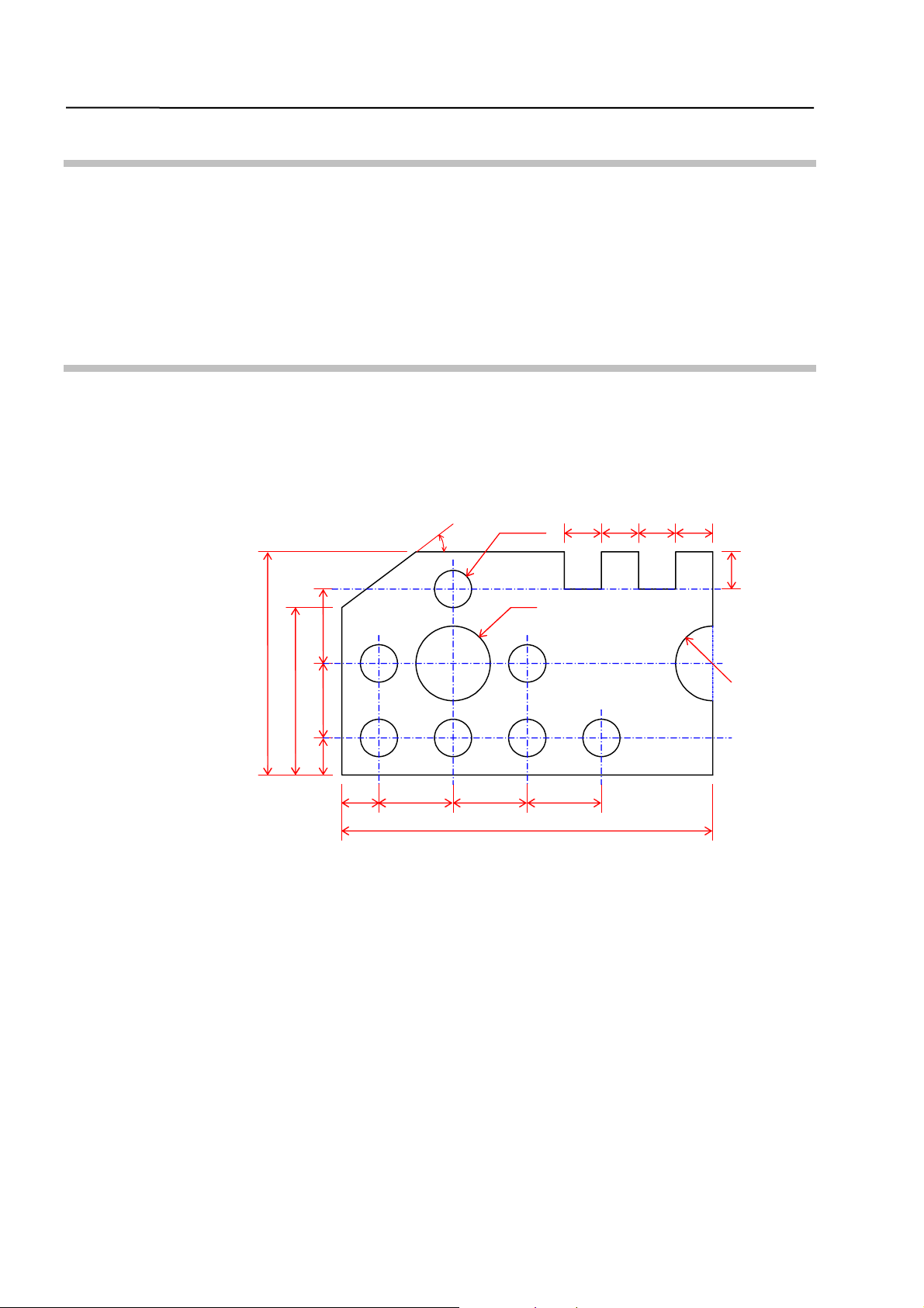
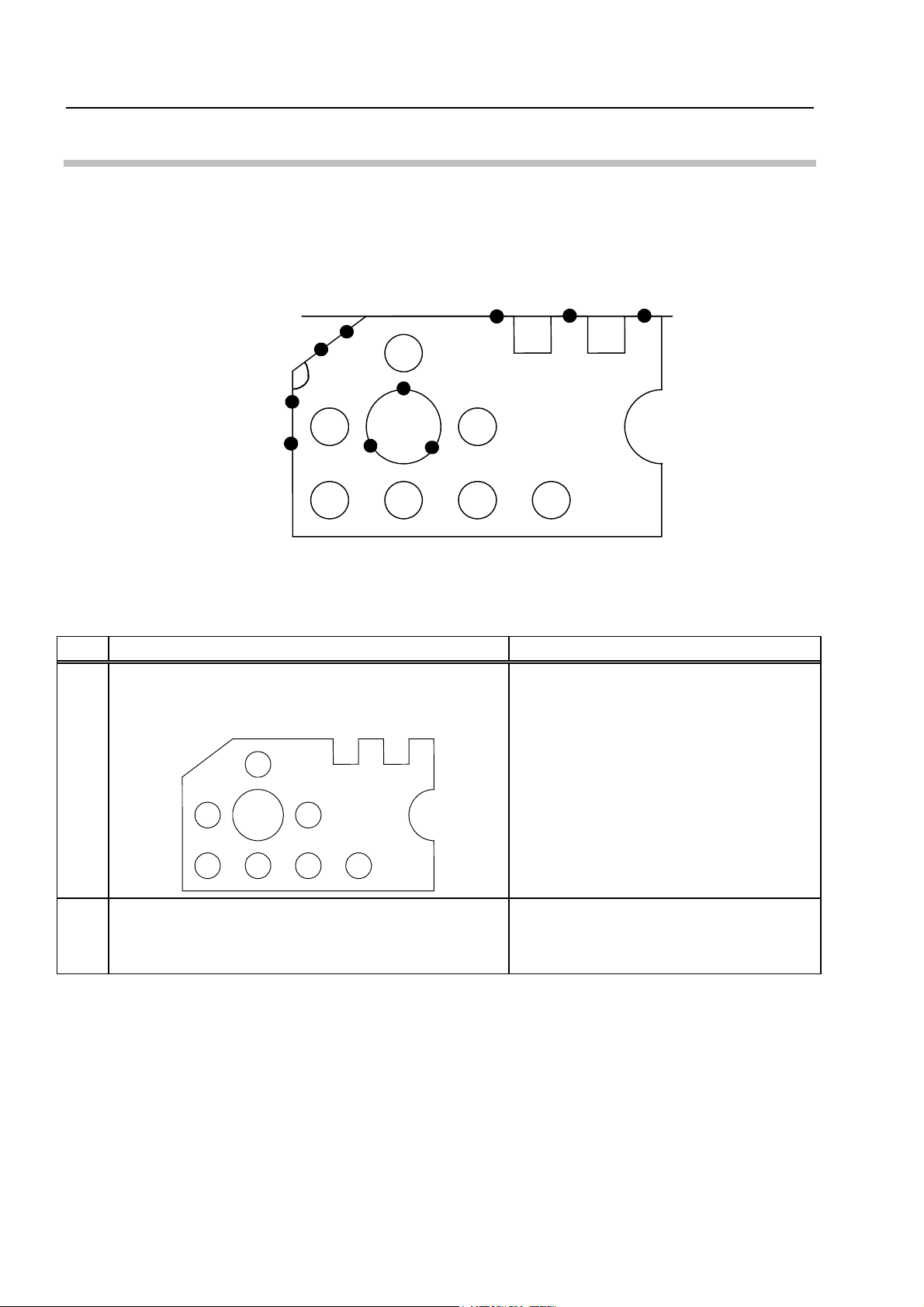
Model Workpiece
The model workpiece shown below is used in all the examples presented.
This model workpiece is designed for practice purposes; dimensional precision is not
guaranteed. Therefore, it should be noted that there may be some differences compared to
the data in the examples presented.
30°
7-φ2
2
2
2
2
2
4
4
12
9
4
2
2
4
4
4
20
R2
ii
No. 99MBA038A

Table of Contents
CONVENTIONS USED IN THIS MANUAL ......................................................................................................... i
Introduction.......................................................................................................................................................ii
Model Workpiece ..............................................................................................................................................ii
1 Before Starting Measurements.............................................................................................................1-1
1.1 Outline of Data Processing Unit .................................................................................................1-1
1.1.1 Appearance ........................................................................................................................1-1
1.1.2 Key Panel Layout...............................................................................................................1-2
1.1.3 Elements of LCD Screen ...................................................................................................1-3
1.1.4 Measurement Screen.........................................................................................................1-4
1.2 Preparing for Measurement ........................................................................................................1-5
1.2.1 Turning On the Power .......................................................................................................1-5
1.2.2 Setting Printer Output to ON (when printer is connected) ............................................1-6
2 Basic Measurements .............................................................................................................................2-1
2.1 Measuring a Circle .......................................................................................................................2-1
2.2 Measuring Angle Between Two Edges ......................................................................................2-3
2.3 Measuring a Width .......................................................................................................................2-5
2.4 Measuring Distance Between Two Circles................................................................................2-7
3 Aligning Part Coordinate System.........................................................................................................3-1
3.1 Aligning Part Coordinate System...............................................................................................3-1
3.2 Aligning Part Coordinate System Using Edges as Reference.................................................3-2
3.3 Aligning Part Coordinate System Using Circle Centers as Reference ...................................3-4
4 Applied Measurements..........................................................................................................................4-1
4.1 Multi-point Measurement ............................................................................................................4-1
4.2 Selecting and Outputting Required Measurement Items Only................................................4-4
4.3 Recalling Measured Features to Construct a New Feature .....................................................4-6
4.4 Performing Tolerance Judgment................................................................................................4-9
5 AI Measurement .....................................................................................................................................5-1
5.1 AI Measurement Function ...........................................................................................................5-1
5.2 Performing AI Measurement .......................................................................................................5-2
SERVICE NETWORK
No. 99MBA038A
iii

MEMO
iv
No. 99MBA038A
1 Before Starting
1
Measurements
This chapter presents practice on the preparations which precede
measurements using this data processing unit.
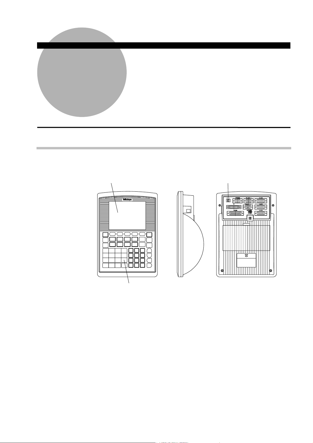
1.1 Outline of Data Processing Unit
1.1.1 Appearance
Display portion (LCD)
Power switch
No. 99MBA038A
Key panel
Fig. 1-1-1
1-1
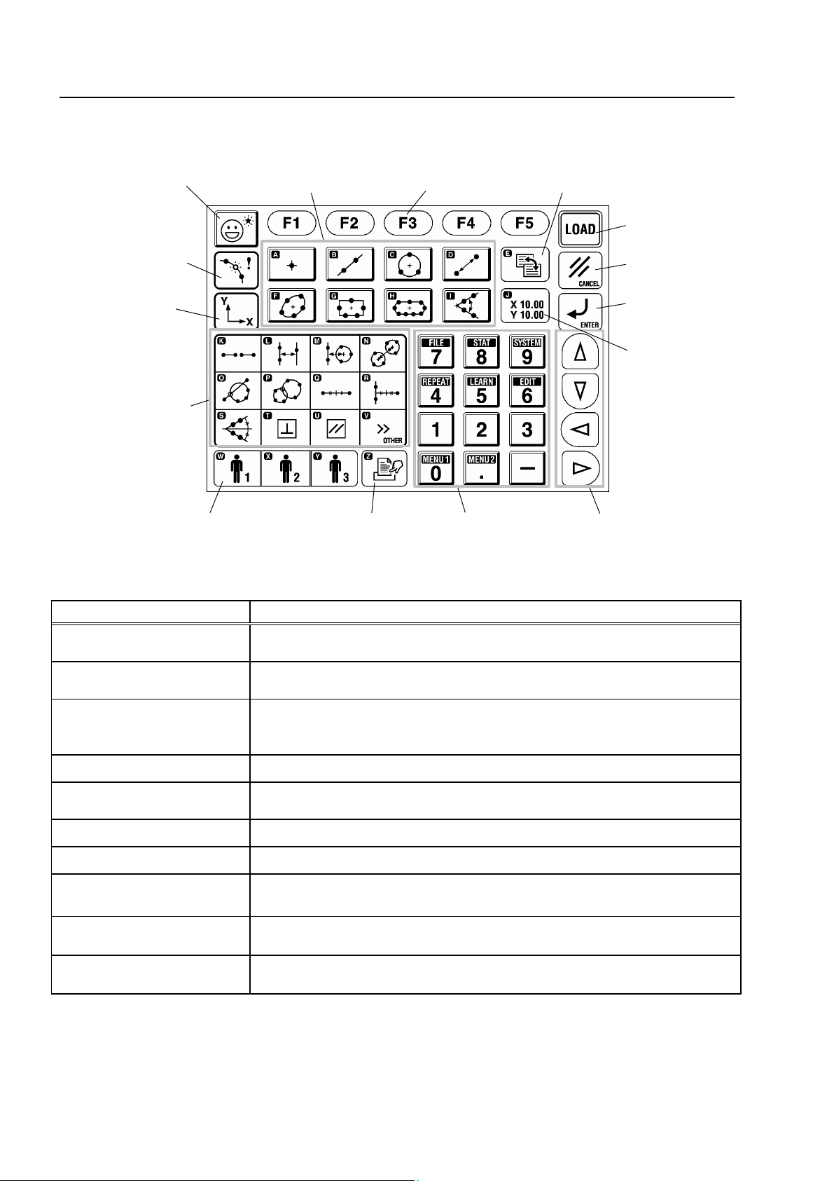
1.1.2 Key Panel Layout
AI measurement key
Basic feature measurement
command keys
Function keys
Screen switching key
[LOAD] key
Coordinate data
input style key
Coordinate
system
alignment menu
key
Measurement
macro command
keys
Key Function
Basic feature measurement
command keys
Measurement macro
command keys
Function keys
[CANCEL] key
[ENTER] key
Counter function
key
Manual print key
Numeric keys
Cursor keys User-defined menu keys
Fig. 1-1-2
Table 1-1-1 (No. 1)
Used to measure and calculate basic geometric shapes.
Used to measure and calculate width, pitch, perpendicularity, and other
values that are not basic features.
Used to select the icon for a function that can be used in a command which
is being executed.
The keys correspond to icons with function key numbers (F1, F2, ... F5).
[LOAD] key Used to input a measured point.
[CANCEL] key Cancels a measured point, or goes back to the immediately previous menu.
[ENTER] key Enters the selection or entry, and goes to the next step.
Cursor keys Used to move the cursor or select a parameter.
Numeric keys
Coordinate system alignment
menu key
Coordinate data input style
key
Used to input numerical values, such as when entering a nominal value.
These keys are also used to select menus shown on the LCD.
Used to set or change the coordinate system.
Used to change the coordinate data input style.
1-2
No. 99MBA038A
1. Before Starting Measurements
Table 1-1-1 (No. 2)
Key Function
AI measurement key
Screen switching key
Counter function key Uses the data processing unit as a simple counter.
Manual print key Prints the measurement results displayed on the screen.
Automatically recognizes the type of the measured basic feature and outputs
the results when measured points are input.
Switches the screen display mode (measurement screen, counter display
screen, etc.).
User-defined menu keys
TIP
Keys with a letter of the alphabet in their upper left corner, such as
to enter an alphabetic text, such as a file name and a comment.
Executes a previously registered part program or user-defined macro
command.
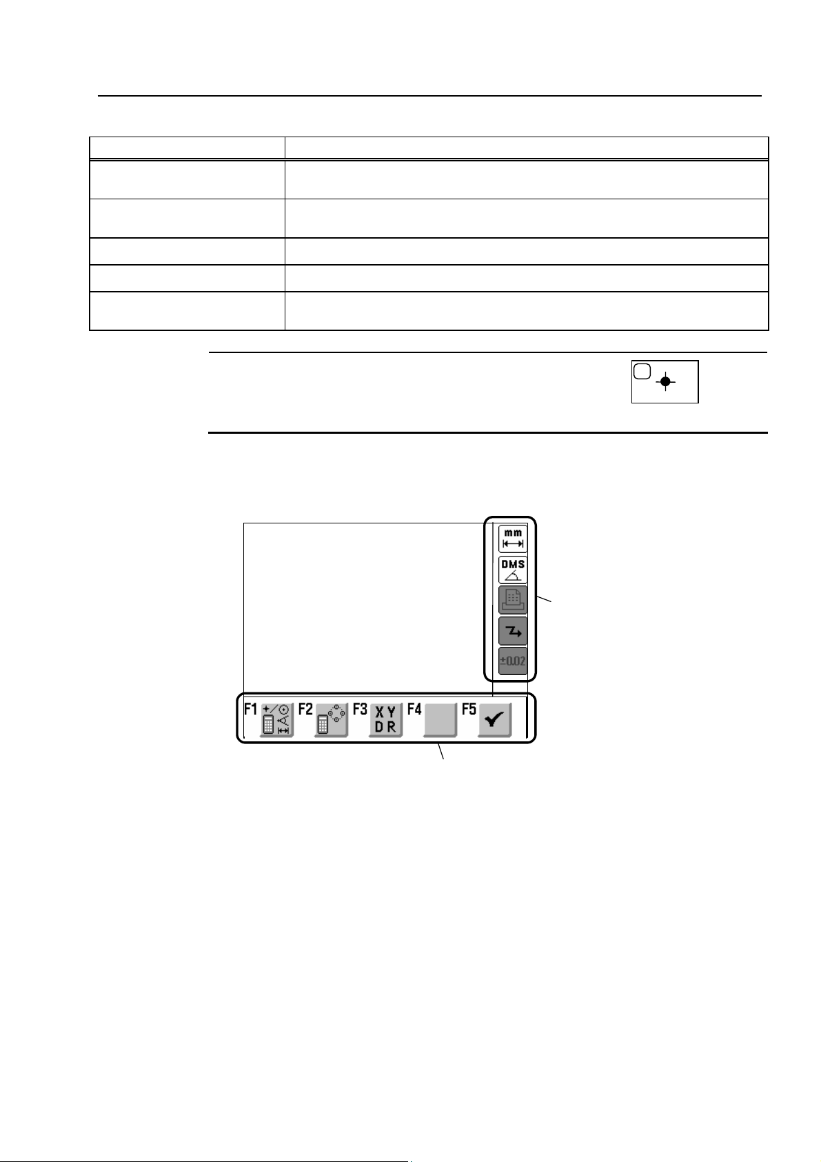
1.1.3 Elements of LCD Screen
Main display area
Status display area
A
, are used
[Main display area]
[Status display area]
[Function keys’ icon display area]
No. 99MBA038A
Function keys’ icon display area
Fig. 1-1-3
Displays counter values, measurement results, operation guidance, etc.
Displays information on the currently set functions.
Displays icons for the functions that can be used with a command which is being executed.
1-3
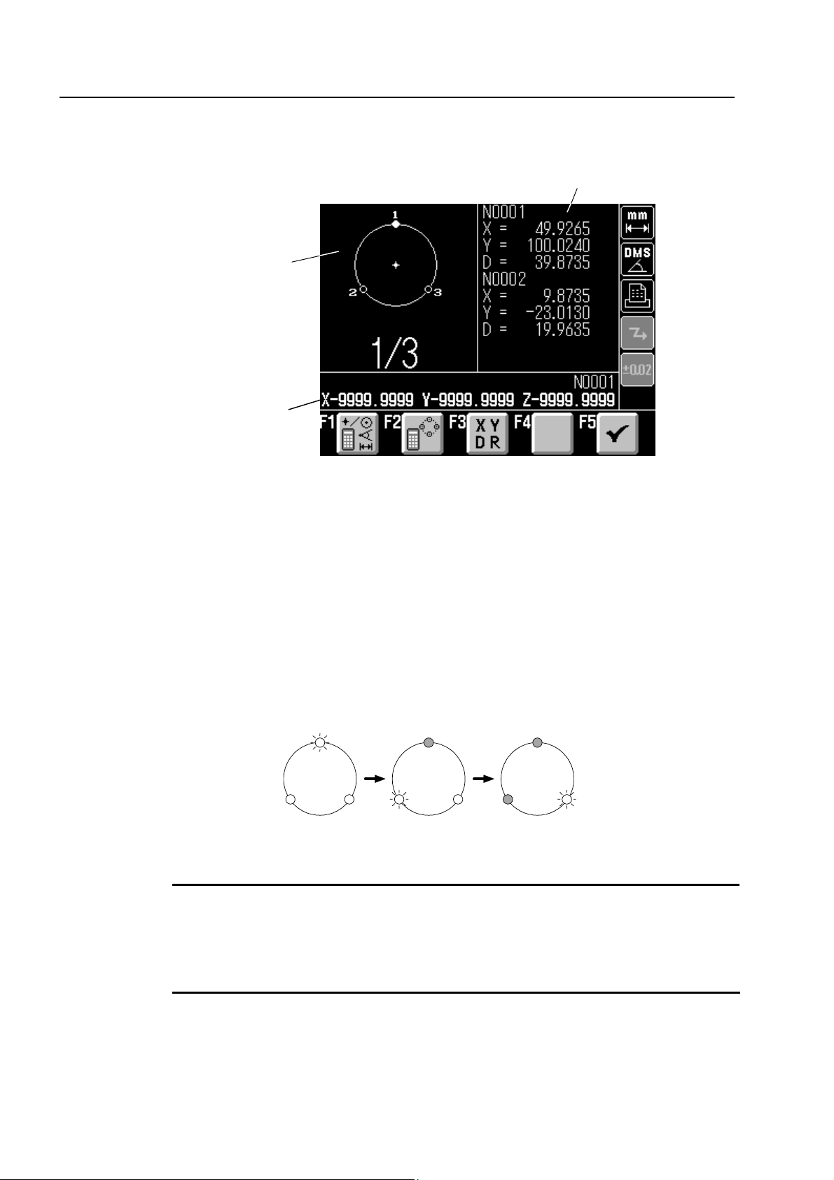
1.1.4 Measurement Screen
<Measurement standby screen (example of circle measurement)>
Navigation
window
Counter
F1: Recalls the measured features and performs calculations, etc.
F2: Recalls the measured features to adopt the representative point coordinates of those
features as measured points for the current measurement.
F3: Changes the measurement conditions ("Output Items", "Auto.MeasuringCompletion").
F4: (Enables/disables input of measured points based on edge detection if OPTOEYE is
mounted.)
F5: Completes the input operation of measurement points and outputs results at the multi-point
measurement.
In the navigation window, the next location to be measured flashes to navigate the next
measuring position. The flashing location moves as shown below, each time a point is entered.
1
Circle
Fig. 1-1-4
1
Measurement result window
1
1-4
3
2
2
1/3 2/3 3/3
3
23
Fig. 1-1-5
TIP
• When the results are displayed at the end of the measurement, the navigation window
returns to its initial input standby state (“1/3” in the above figure), and the same
measurement is repeated automatically.
• To perform a different measurement, press a different measurement command key.
No. 99MBA038A
1.2 Preparing for Measurement
[Purpose of Practice]
To learn the operating procedures from turning on the power to getting the state where
measurement commands can be executed.
[Operating Procedure]
1) Turn on the power for the data processing unit.
2) Set the printer output to ON.
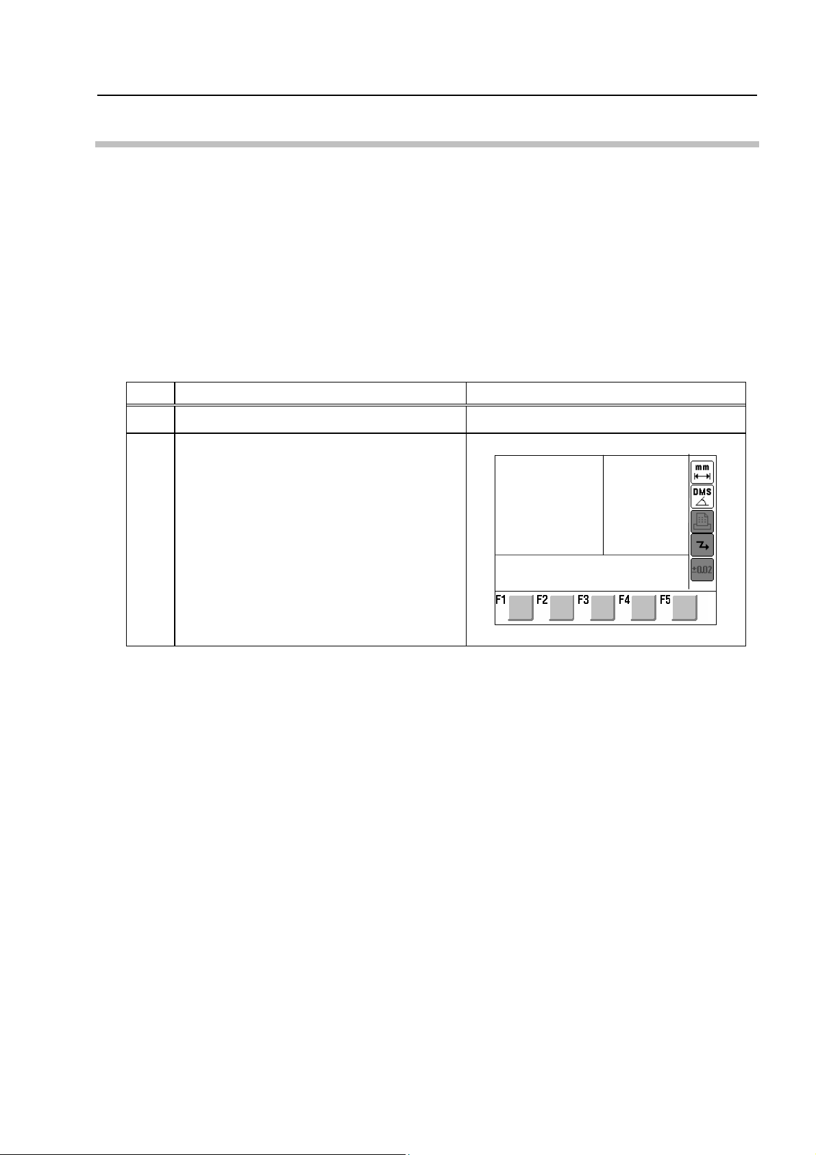
1.2.1 Turning On the Power
Table 1-2-1
No. Operation Screen display and remarks
1. Before Starting Measurements
1 Turn the power switch to ON.
The Startup Screen is displayed.
2
A little bit after the opening screen is
displayed, the startup screen shown at right is
displayed.
–
Press a measurement or menu key.
X 0.000 Y 0.000
No. 99MBA038A
1-5
1.2.2 Setting Printer Output to ON (when printer is connected)
NOTE
No. Operation Screen display and remarks
1
Be sure to turn on the printer power before setting the printer output to ON.
Table 1-2-2
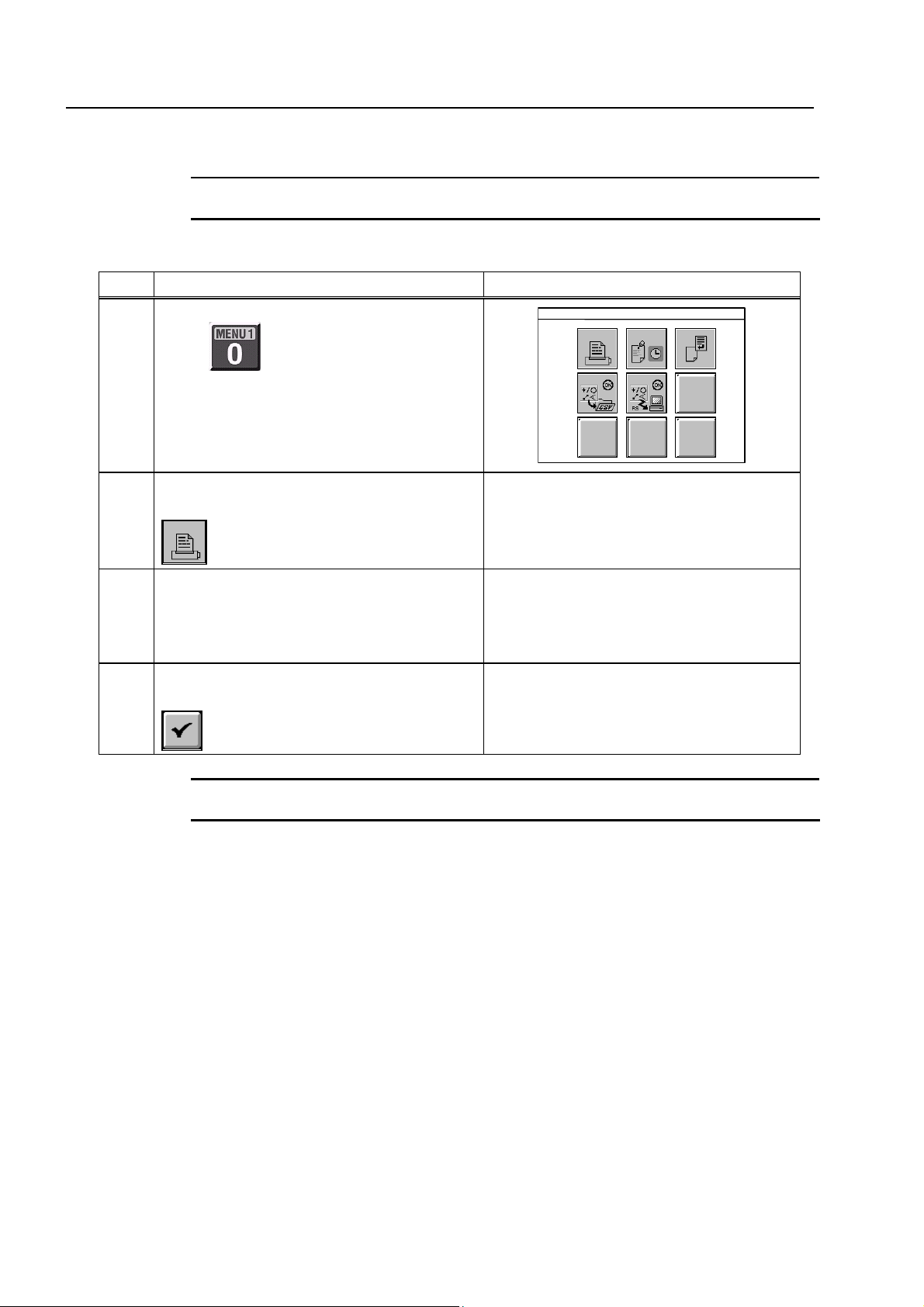
Selecting menu function
Press
.
MENU 1: Output Function Menu
7 8 9
4 5
Selecting printer setting
2
Press the numeric key corresponding to
.
Selecting ON for printer
3
Use the left and right cursor keys to select “All
Results w/o Command Names” for “Contents
to Be Printed”.
Finishing printer setting
4
Press the [F5] function key corresponding to
.
<Remarks>
Measurement results subsequent to this
setting are printed by the printer.
–
–
1-6
TIP
To cancel printer output, select “None” in step 3 above.
No. 99MBA038A

2 Basic Measurements
2
2.1 Measuring a Circle
[Purpose of Practice]
To measure a circle using the model workpiece.
This chapter presents practice for basic measurement procedures
using the model workpiece.
φ4
Fig. 2-1-1
[Operating Procedure]
Table 2-1-1
No. Operation Screen display and remarks
Preparing the workpiece
1
Set the model workpiece on the XY table as shown below,
and focus on it.
–
Measurement function selection
2
Press
.
–
No. 99MBA038A
2-1

No. Operation Screen display and remarks
Measuring circle (A)
3
At any three points on the circumference of circle (A),
center the projection screen crosshairs and then press the
[LOAD] key.
1
(A)
2
3
Results display
4
The circle (A) measurement results are displayed on the
screen.
D
NOTE
• The three points that are measured should be spaced as far apart from each other as
possible on the circumference in order to measure the circle precisely.
<Remarks>
Follow the information displayed on the
screen to perform the measurement.
N0001
X =
Y =
D = 4.018
*.***
*.***
Diameter
• The X and Y coordinate results indicating the circle’s center position vary depending on
the position and orientation of the model workpiece on the XY table. In order to obtain
measurement results that match the dimensions shown in the section titled “Model
Workpiece”, before starting the measurement, perform the operation described in
Section 3.2 “Aligning Part Coordinate System Using Edges as Reference”.
TIP
• If an incorrect position was measured, it is possible to cancel the measured point data
by pressing the [CANCEL] key prior to entering the last measurement point. If the
[CANCEL] key is held down, the system returns to the standby state for the first
measurement point.
• The last measurement point cannot be canceled. If the last measurement point is not
correct, redo the measurement.
2-2
No. 99MBA038A

2. Basic Measurements
2.2 Measuring Angle Between Two Edges
[Purpose of Practice]
To measure the angle between two edges using the model workpiece.
(A)
150°
[Operating Procedure]
No. Operation Screen display and remarks
Preparing the workpiece
1
Set the model workpiece on the XY table as shown below,
and focus on it.
(B)
Fig. 2-2-1
Table 2-2-1
Measurement function selection
2
Press
Measuring edge (A)
3
Measure edge (A) at two points.
.
2
(A)
–
–
<Remarks>
Follow the information displayed on the
1
screen to perform the measurement.
No. 99MBA038A
2-3

No. Operation Screen display and remarks
Measuring edge (B)
4
Measure edge (B) at two points.
4
3
(B)
Results display
5
The measurement results (A1, A2) for the angle formed by
edge (A) and edge (B) are displayed on the screen.
A2
A1
NOTE
• Note that the obtained angle (A1) varies depending on the order in which the edges are
measured, as shown below.
<Remarks>
Follow the information displayed on the
screen to perform the measurement.
N0001
X =
*.***
Y =
*.***
A1= 150.0142
A2= 209.5818
1
2
Measurement
method 1
4
3
4
1
2
Measurement
method 2
3
3
4
Measurement
method 3
2
1
3
4
Measurement
method 4
1 2
• The X and Y coordinate results of the intersection point vary depending on the position
and orientation of the model workpiece on the XY table. In order to obtain measurement
results that match the dimensions shown in the section titled “Model Workpiece”, before
starting the measurement, perform the operation described in Section 3.2 “Aligning Part
Coordinate System Using Edges as Reference”.
• Angle units can be switched between degrees (decimal notation) and degrees, minutes
and seconds (sexagesimal notation). See Chapter 6 of the “Software Guide” for the
switching procedure.
2-4
No. 99MBA038A

2.3 Measuring a Width
[Purpose of Practice]
To measure a width using the model workpiece.
2. Basic Measurements
(A)
2
(B)
Fig. 2-3-1
[Operating Procedure]
Table 2-3-1
No. Operation Screen display and remarks
Preparing the workpiece
1
Set the model workpiece on the XY table as shown below,
and focus on it.
Measurement function selection
2
Press
Measuring side (A)
3
Measure side (A) at two points.
.
(A)
–
–
<Remarks>
Follow the information displayed on the
1
2
screen to perform the measurement.
No. 99MBA038A
2-5

No. Operation Screen display and remarks
Measuring side (B)
4
Measure side (B) at one point.
(B)
1
5 The width measurement result (LC) is displayed on the
screen.
LC
NOTE
When measuring a width, be sure to enter two points for the edge being measured first,
and then enter one remaining point for the edge being measured second.
<Remarks>
Follow the information displayed on the
screen to perform the measurement.
N0001
LC= 2.001
TIP
• If an incorrect position was measured, it is possible to cancel the measured point data
by pressing the [CANCEL] key prior to entering the last measurement point. If the
[CANCEL] key is held down, the system returns to the standby state for the first
measurement point.
• The last measurement point cannot be canceled. If the last measurement point is not
correct, redo the measurement.
2-6
No. 99MBA038A
2. Basic Measurements
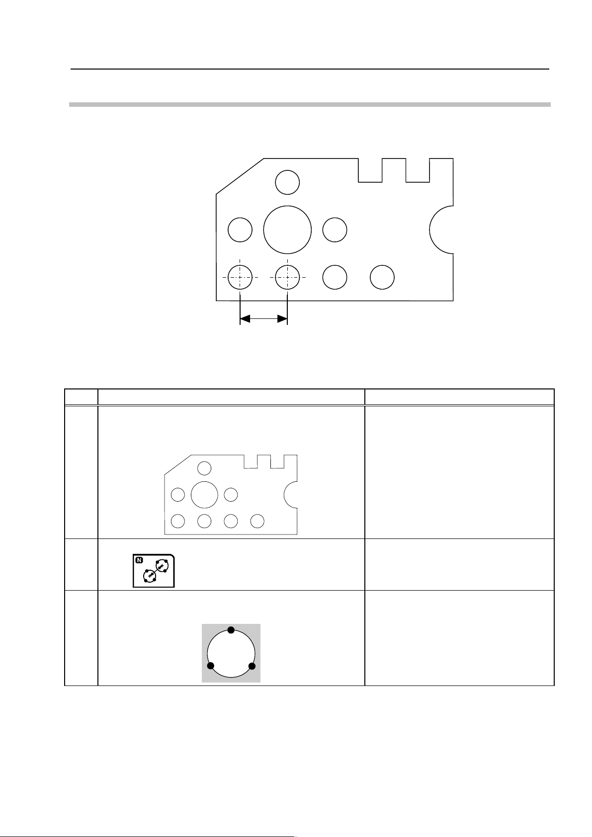
2.4 Measuring Distance Between Two Circles
[Purpose of Practice]
To measure two circles to obtain the distance between them.
(A)
(B)
4
Fig. 2-4-1
[Operating Procedure]
Table 2-4-1
No. Operation Screen display and remarks
Preparing the workpiece
1
Set the model workpiece on the XY table as shown below,
and focus on it.
–
Measurement function selection
2
Press
Measuring circle (A)
3
Measure circle (A) at three points.
No. 99MBA038A
.
<Remarks>
Follow the information displayed on the
1
(A)
3
2
screen to perform the measurement.
–
2-7

No. Operation Screen display and remarks
Measuring circle (B)
4
Measure circle (B) at three points.
1
(B)
3
2
Results display
5
The measurement results (LC, LS, LL) for the distance
between circle (A) and circle (B) are displayed on the
screen.
(A)
(B)
LS
LC
LL
<Remarks>
Follow the information displayed on the
screen to perform the measurement.
N0001
LC= 4.006
LL= 6.011
LS= 2.001
XD= *.***
YD= *.***
• The XD and YD measurement results indicating the distance between the two circles
TIP
along the X and Y axes vary depending on the position and orientation of the model
workpiece on the XY table. In order to obtain measurement results that match the
dimensions shown in the section titled “Model W orkpiece”, before starting the
measurement, perform the operation described in Section 3.2 “Aligning Part Coordinate
System Using Edges as Reference”.
2-8
No. 99MBA038A

3 Aligning Part Coordinate
3
System
This chapter presents practice on the procedures for aligning the
part coordinate system using the model workpiece.
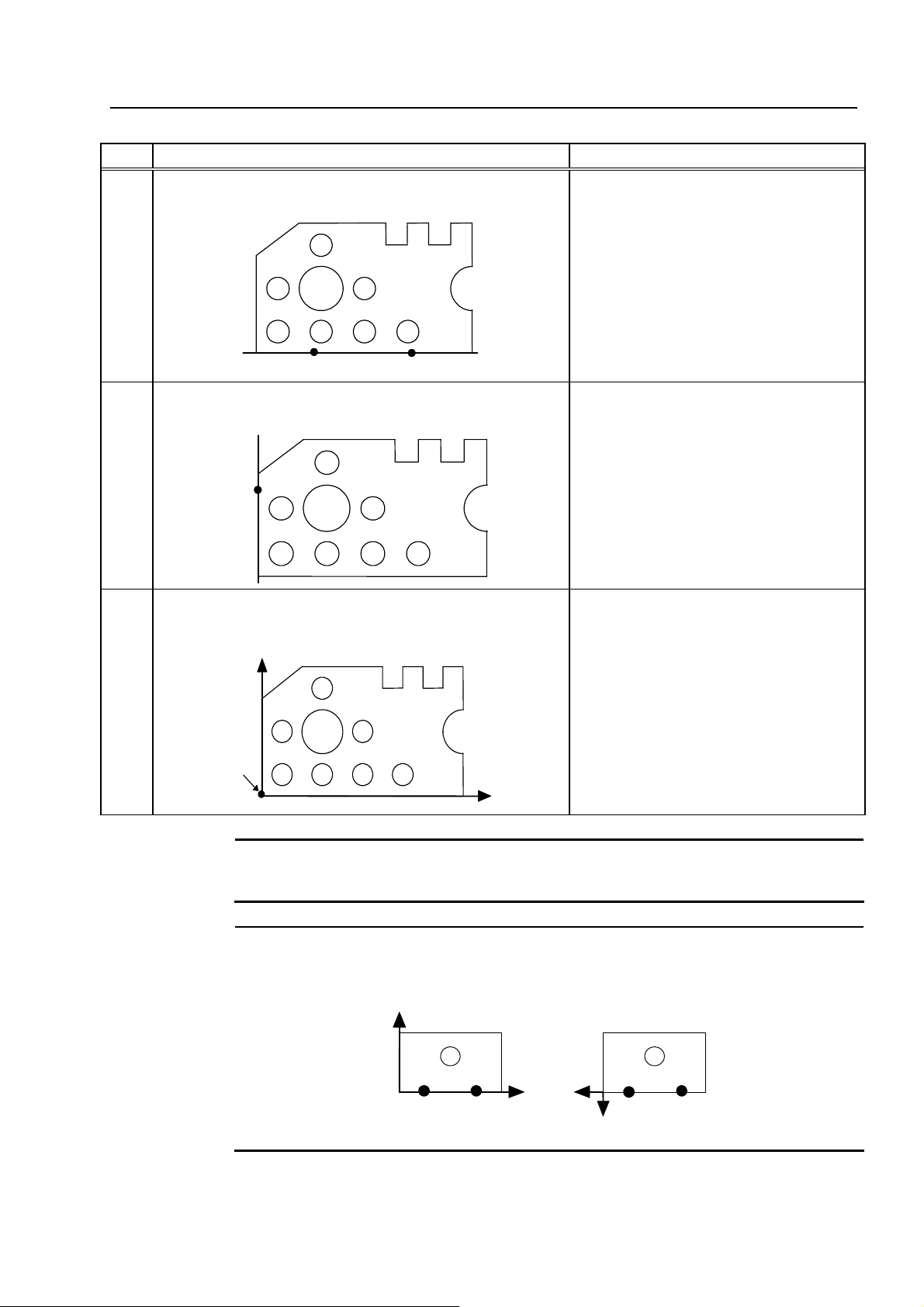
3.1 Aligning Part Coordinate System
When the data processing unit is turned on, the coordinate values in the coordinate system
matching the moving directions of the XY table are output as measurement results. (See Fig.
3-1-1.)
Y
(x, y)
(0, 0)
Fig. 3-1-1
Therefore, in order to correctly evaluate information such as the center coordinates of a circle
on a workpiece as dimensions, the coordinate system must be aligned to match the workpiece’s
position and orientation.
The aligned coordinate system is called the part coordinate system (PCS). (See Fig. 3-1-2.)
X
No. 99MBA038A
Y
Once the part coordinate system is set, it is possible to obtain precise measurements and
calculations even if the workpiece’s orientation is not adjusted to be parallel with the moving
directions of the XY table.
(x, y)
(0, 0)
Fig. 3-1-2
X
3-1

3.2 Aligning Part Coordinate System Using Edges as Reference
[Purpose of Practice]
To align the part coordinate system based on two edges that are perpendicular to each
other, using the model workpiece.
[Description of Operation]
The part coordinate system is set using the coordinate system alignment macro command
(1).
Y
X
(0, 0)
Fig. 3-2-1
[Operating Procedure]
Table 3-2-1
No. Operation Screen display and remarks
Preparing the workpiece
1
Set the model workpiece on the XY table as shown below,
and focus on it.
–
Selecting the coordinate system alignment menu
2
Press
The coordinate system alignment function menu is
displayed.
Selecting the coordinate system alignment macro
3
command (1)
Press the numeric key corresponding to
.
–
–
.
3-2
No. 99MBA038A
3. Aligning Part Coordinate System
No. Operation Screen display and remarks
Measuring edge (A)
4
Measure edge (A) at two points.
(A)
(2)
Measuring edge (B)
5
(1)
Measure edge (B) at one point.
(3)
(B)
The part coordinate system is completed.
6
The part coordinate system is completed as shown below.
Y
Origin
X
<Remarks>
Follow the information displayed on the
screen to perform the measurement.
<Remarks>
Follow the information displayed on the
screen to perform the measurement.
<Remarks>
Once the part coordinate system is
completed, coordinate values are
defined from the origin, which serves as
a reference.
The part coordinate system established
in this example matches the coordinate
system shown in the section titled
“Model Workpiece”. Therefore, you can
refer to the drawing in that section while
practicing measurements.
NOTE
No. 99MBA038A
See Chapter 5 of the “Software Guide” for further details about the coordinate system
TIP
alignment functions.
When measuring edge (A), note the order in which the measurements are performed, as
the direction of the coordinate system’s reference axis varies depending on the
measurement order.
Y
X
Y
(2)
(A)
(1)
(1)
(A)
X
(2)
The X-axis direction orients from the first measured point to the second measured point.
3-3

3.3 Aligning Part Coordinate System Using Circle Centers as Reference
[Purpose of Practice]
To align the part coordinate system based on two circle centers, using the model
workpiece.
[Description of Operation]
The part coordinate system is set using the coordinate system alignment macro command
(4).
Y
(A)
(B)
X
(0, 0)
Fig. 3-3-1
[Operating Procedure]
Table 3-3-1
No. Operation Screen display and remarks
Preparing the workpiece
1
Set the model workpiece on the XY table as shown below,
and focus on it.
–
3-4
Selecting the coordinate system alignment menu
2
Press
The coordinate system alignment function menu is
displayed.
Selecting the coordinate system alignment macro
3
command (4)
Press the numeric key corresponding to
.
–
–
.
No. 99MBA038A

3. Aligning Part Coordinate System
Y
No. Operation Screen display and remarks
Selecting the coordinate data input style
4
Press
.
Then, from the icon menu, press the numeric key
corresponding to
Measuring circle (A)
5
.
Measure circle (A) at three points.
(A)
Measuring circle (B)
6
Measure circle (B) at three points.
(B)
–
<Remarks>
Follow the information displayed on the
screen to perform the measurement.
<Remarks>
Follow the information displayed on the
screen to perform the measurement.
The part coordinate system is completed.
7
The part coordinate system is completed as shown below.
Origin
(A)
(B)
<Remarks>
Once the part coordinate system is
completed, coordinate values are
defined from the origin, which serves as
a reference.
X
No. 99MBA038A
3-5

NOTE
When measuring circle (A) and circle (B), note the order in which the measurements are
performed, as the direction of the coordinate system’s reference axis varies depending on
the measurement order.
Y
(A)
(1)
(B)
(2)
X
(A)
(2)
X
(B)
(1)
Y
The X-axis direction orients from the center of the first measured circle to the center of
the second measured circle.
TIP
After this measurement example, the coordinate data input style remains “Circle center
input”.
Use the following procedure to reset the coordinate data input style to “Actual point input”.
Table 3-3-2
No. Operation Screen display and remarks
Selecting the coordinate data input style
1
Press
.
Then, from the icon menu, press the numeric key
corresponding to
.
TIP
• See Chapter 5 of the “Software Guide” for further details about the coordinate system
alignment functions.
• See Chapter 4 of the “Software Guide” for further details about the coordinate data input
style.
–
3-6
No. 99MBA038A

4 Applied Measurements
4
4.1 Multi-point Measurement
[Purpose of Practice]
To practice taking measurements using multiple points. In this section, a line is measured
at three or more points to determine the angle formed by the line and the X-axis, and the
straightness of the line.
This chapter presents practice on applied measurement procedures
using the model workpiece.
(A)
Fig. 4-1-1
No. 99MBA038A
4-1

[Operating Procedures]
Table 4-1-1
No. Operation Screen display and remarks
Preparing the workpiece
1
Set the model workpiece on the XY table as shown
below, and focus on it.
–
Aligning the part coordinate system
2
For the aligning procedure, see Section 3.2 “Aligning
Part Coordinate System Using Edges as Reference”.
Measurement function selection
3
Press
.
The explanation for the operations from
step 3 onward assumes that the part
coordinate system has been aligned.
–
Changing measurement conditions
4
Press the [F3] function key corresponding to
Setting “Auto.MeasuringCompletion” to OFF
5
Press the [F3] key to set the
“Auto.MeasuringCompletion” to “OFF”.
Completion of changing measurement conditions
6
Press the [F5] function key corresponding to
Measuring edge (A)
7
Measure edge (A) at three or more points.
(A)
n
3
2
1
.
Auto.MeasuringCompletion: OFF
: Press [F3] to switch the status.
–
.
–
<Remarks>
Follow the information displayed on the
screen to perform the measurement.
4-2
No. 99MBA038A

4. Applied Measurements
No. Operation Screen display and remarks
Completing the measurement
8
When two or more measured points required for
measuring a line are input,
Press the corresponding [F5] function key to complete
the measurement.
Results display
9
The measurement results for edge (A) are displayed on
the screen.
(A)
n
3
2
1
TIP
• To perform measurements in such a manner that a multi-point measurement is
automatically completed when the predetermined number of measuring points have
been input, reset “Auto.MeasuringCompletion” to “ON” (see steps 4 through 6).
is displayed.
CX
–
N0001
CX = 90.0215
F1 = 0.154
• The multi-point measurement can be performed using the same procedure on points,
circles, and ellipses in addition to lines.
No. 99MBA038A
4-3

4.2 Selecting and Outputting Required Measurement
Items Only
[Purpose of Practice]
To practice selecting and outputting just the required items as measurement results. In this
section, the point & angle feature formed by two adjacent edges is measured to output only
the intersection angle (A1).
(A)
150°
(A1)
[Operating Procedures]
No. Operation Screen display and remarks
Preparing the workpiece
1
Set the model workpiece on the XY table as shown
below, and focus on it.
(B)
Fig. 4-2-1
Table 4-2-1
4-4
Measurement function selection
2
Press
Starting output item selection
3
Press the [F3] function key corresponding to
.
–
–
.
–
No. 99MBA038A

4. Applied Measurements
No. Operation Screen display and remarks
Selecting output item
4
Use the up and down cursor keys
highlight the item to be selected.
Each time the [ENTER] key is pressed, an asterisk
(*) appears to the left of the highlighted item, or is
removed from the item.
In this example, place an asterisk (*) next to “Angle:
A1” only.
to
Coord: X
Coord: Y
RadDist: L
Angle: A
*
Angle: A1
Coord: Y
RadDist: L
Angle: A
*
Angle: A1
Angle: A2
<Remarks>
In some cases, it may not be possible to
display all of the output items at once. In such
cases, scroll through the screen to view the
hidden items using the up and down cursor
keys
.
Completing output item selection
5
Press the [F5] function key corresponding to
Measuring edges (A) and (B)
6
Measure edges (A) and (B).
(B)
3
1
4
Result display
7
(A)
2
Only the measurement result for the intersection
angle (A1) between edge (A) and edge (B) is
displayed on the screen.
A1
<Remarks>
Only the output items with an asterisk (*) next
.
to them will be output after the measurement.
<Remarks>
Follow the information displayed on the screen
to perform the measurement.
The procedure is the same as steps 3 to 4 in
Section 2.2 “Measuring Angle Between Two
Edges”.
N0001
A1 = 150.1826
No. 99MBA038A
TIP
The output item selection result made in the above example remains in effect until the
power is turned off.
4-5

4.3 Recalling Measured Features to Construct a New
Feature
[Purpose of Practice]
This section presents practice on recalling measured features to calculate a new feature.
In this section, the measurement results for two circles (A) and (B) are recalled to calculate
the midpoint between them.
(A)
[Operating Procedures]
No. Operation Screen display and remarks
Preparing the workpiece
1
Set the model workpiece on the XY table as shown
below, and focus on it.
(B)
Fig. 4-3-1
Table 4-3-1
–
Aligning the part coordinate system
2
For the aligning procedure, see Section 3.2 “Aligning
Part Coordinate System Using Edges as Reference”.
Selecting the circle feature measurement command
3
Press
.
The explanation for the operations from
step 3 onward assumes that the part
coordinate system has been aligned.
–
4-6
No. 99MBA038A

4. Applied Measurements
No. Operation Screen display and remarks
Measuring circles (A) and (B)
4
Measure circles (A) and (B) using the same procedure
as in step 3 of Section 2.1 “Measuring a Circle”.
1
2
3
Results display
5
The measurement results for circles (A) and (B) are
displayed on the screen.
D
D
Y
X
X
Selecting the point feature measurement command
6
Press
.
<Remarks>
Follow the information displayed on the
screen to perform the measurement.
N0001
X = 2.055
Y = 2.008
D =
N0002
X = 6.013
Y = 2.010
D =
• • • • •
• • • • •
–
Displaying the feature construction menu
7
Press the [F1] function key corresponding to
Selecting the midpoint construction
8
Press the numeric key corresponding to
Selecting the measured features
9
Use the up and down cursor keys
to highlight
the measurement result for circle (A) and then press the
[ENTER] key. Then perform the same operation for the
measured circle (B).
.
.
:
:
:
:
*10 {
*11 {
–
–
• • • •
X =
:
Y =
D =
• • • •
• • • •
:
:
:
No. 99MBA038A
4-7

No. Operation Screen display and remarks
Result display
10
The coordinates of the midpoint between circle (A) and
circle (B) are displayed on the screen.
Y
X
N0003
X = 4.034
Y = 2.009
4-8
No. 99MBA038A

4.4 Performing Tolerance Judgment
[Purpose of Practice]
To compare measurement results with nominal values and tolerance zones, and to make a
GO/NG judgment.
In this section, circle (A) is measured and the tolerance judgment is performed.
(A)
Fig. 4-4-1
[Operating Procedures]
Table 4-4-1
4. Applied Measurements
No. Operation Screen display and remarks
Preparing the workpiece
1
Set the model workpiece on the XY table as shown
below, and focus on it.
–
Aligning the part coordinate system
2
For the aligning procedure, see Section 3.2 “Aligning
Part Coordinate System Using Edges as Reference”.
Selecting Menu 2
3
Press
.
The explanation for the operations from
step 3 onward assumes that the part
coordinate system has been aligned.
–
No. 99MBA038A
4-9
No. Operation Screen display and remarks
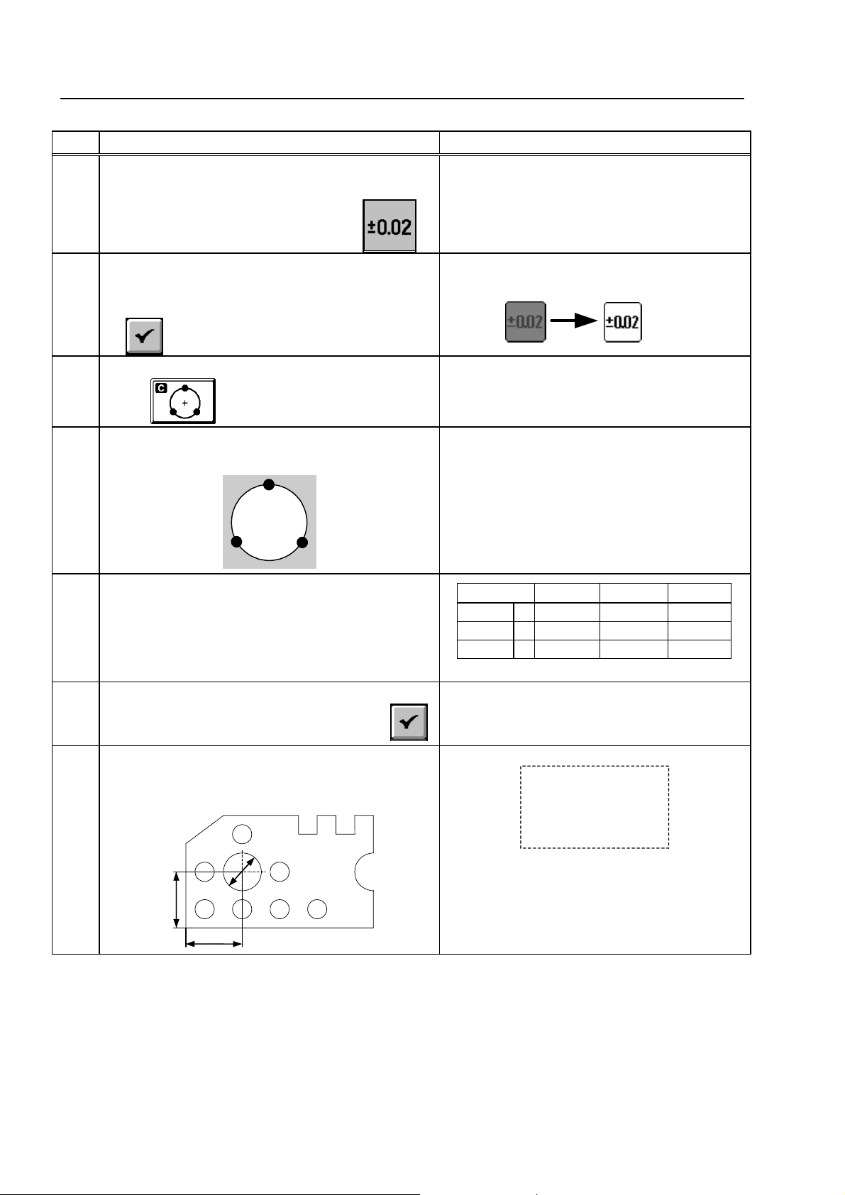
Selecting the command for setting the tolerance
4
judgment function to ON or OFF
Press the numeric key corresponding to
Setting the tolerance judgment function to ON
5
Confirm that “Tolerance Judgment” is set to “ON”,
and then press the [F5] function key corresponding
to
Measurement function selection
6
.
.
<Remarks>
The status display changes as follows.
(OFF) (ON)
–
Press
Measuring circle (A)
7
.
Measure circle (A) at three points.
2
(A)
3
<Remarks>
Follow the information displayed on the screen
to perform the measurement.
1
–
Inputting tolerance data
8
Move the cursor to the input columns and enter the
nominal values and tolerance values using the
numeric keys. Note that items with no input data are
not judged.
Completion of inputting the tolerance data
9
Press the [F5] function key corresponding to
Results display
10
The measurement results for circle (A) are
displayed on the screen.
(A)
D
Y
Output Item Nominal U. Tol. L. Tol.
Coord:
Coord: Y 6.000 0.010 -0.010
Dia: D 4.000 0.010 -0.010
.
6.000 0.010 -0.010
X
–
N0001
X = 6.001
Y = 6.005
D1 = 4.018 +NG
<Remarks>
If the deviation exceeds the tolerance zone,
“+NG” or “-NG” is displayed as GO/NG
X
judgment result.
4-10
No. 99MBA038A

5 AI Measurement
5
5.1 AI Measurement Function
The AI measurement (Artificial Intelligence measurement) is a function of automatically
recognizing the type of the measured basic feature, such as a circle, a straight line, etc. from
measured points data. The following types of basic feature can be automatically recognized by
the system using the AI function.
This chapter presents practice for measurements utilizing artificial
intelligence (AI), using the model workpiece.
Table 5-1-1
Type of feature
1 Point
2 Line
3 Circle
4 Distance
5 Ellipse
6 Rectangular hole
7 Slot
8 Point & angle
TIP
See Chapter 4 of the “Software Guide” for further details on the AI function.
Applicable number of
measurement points
1-100
2-100
3-100
2
5-100
5
9
2-50 each Measures two lines.
Remarks
No. 99MBA038A
5-1
5.2 Performing AI Measurement
[Purpose of Practice]
To practice measurements utilizing the AI function using the model workpiece. In this
section, line (A), circle (B) and angle (C) are measured successively in the AI measurement
mode.
(A)
(C)
(B)
Fig. 5-2-1
[Operating Procedure]
Table 5-2-1
No. Operation Screen display and remarks
Preparing the workpiece
1
Set the model workpiece on the XY table as shown
below, and focus on it.
Aligning the part coordinate system
2
For the aligning procedure, see Section 3.2 “Aligning
Part Coordinate System Using Edges as Reference”.
–
The explanation for the operations from
step 3 onward assumes that the part
coordinate system has been aligned.
5-2
No. 99MBA038A

5. AI Measurement
No. Operation Screen display and remarks
Setting the AI measurement function to ON
3
Press
Measuring line (A)
4
.
Measure three points on line (A).
(1) (2)
Completion of line (A) measurement
5
(3)
(A)
After the desired measured points have been entered,
press the [F5] function key corresponding to
<Remarks>
The icon corresponding to the automatically
recognized basic feature type is highlighted.
.
–
–
Results display
6
The measurement results for line (A) are displayed.
Measuring circle (B)
7
Measure three points on circle (B).
(1)
(B)
(2)
(3)
N0001
CX = 0.0835
F1 = 0.012
<Remarks>
The icon corresponding to the automatically
recognized basic feature type is highlighted.
No. 99MBA038A
5-3

No. Operation Screen display and remarks
Completion of circle (B) measurement
8
After the desired measured points have been entered,
press the [F5] function key corresponding to
Results display
9
The measurement results for circle (B) are displayed.
Measuring angle (C)
10
Measure four points on the two lines forming angle
(C).
(4)
(3)
(C)
(1)
(2)
.
<Remarks>
The icon corresponding to the automatically
recognized basic feature type is highlighted.
–
N0002
X = 6.083
Y = 6.012
D = 4.000
Completion of angle (C) measurement
11
After the desired measured points have been entered,
press the [F5] function key corresponding to
Results display
12
The measurement results for angle (C) are displayed.
.
–
N0003
X = 0.083
Y = 0.012
A1 = 119.4837
A2 = 240.1123
TIP
If the automatically recognized feature type is not appropriate, the feature type can be
manually corrected. See Chapter 4 of the “Software Guide” for information on how to
correct feature type.
5-4
No. 99MBA038A
 Loading...