


No.99MBC034B3
SERIES No.542
1234567890123456789012345678901212345678901234567890123456789012123456
123456789012345678901234567890121234567890123456789012345678901212345 6
123456789012345678901234567890121234567890123456789012345678901212345 6
123456789012345678901234567890121234567890123456789012345678901212345 6
123456789012345678901234567890121234567890123456789012345678901212345 6
123456789012345678901234567890121234567890123456789012345678901212345EV Counter 6
123456789012345678901234567890121234567890123456789012345678901212345 6
123456789012345678901234567890121234567890123456789012345678901212345 6
123456789012345678901234567890121234567890123456789012345678901212345 6
123456789012345678901234567890121234567890123456789012345678901212345 6
123456789012345678901234567890121234567890123456789012345678901212345 6
123456789012345678901234567890121234567890123456789012345678901212345 6
123456789012345678901234567890121234567890123456789012345678901212345 6
123456789012345678901234567890121234567890123456789012345678901212345 6
123456789012345678901234567890121234567890123456789012345678901212345 6
123456789012345678901234567890121234567890123456789012345678901212345 6
123456789012345678901234567890121234567890123456789012345678901212345 6
1234567890123456789012345678901212345678901234567890123456789012123456
Linear Gage
Counter
User’s Manual
Read this User's Manual thoroughly before operating the instrument. After reading,
retain it close at hand for future reference.
CONVENTIONS USED IN USER'S MANUAL
Safety Precautions
To operate the instrument correctly and safely, Mitutoyo manuals use various safety signs (Signal Words and Safety Alert Symbols) to identify and warn against hazards and potential accidents.
The following signs indicate general warnings:
|
Indicates an imminently hazardous situation |
|
which, if not avoided, will result in serious injury |
DANGER |
or death. |
|
|
|
|
|
Indicates a potentially hazardous situation |
|
which, if not avoided, could result in serious |
CAUTION |
injury or death. |
|
|
|
|
|
Indicates a potentially hazardous situation |
WARNING |
which, if not avoided, may result in minor or |
moderate injury or property damage. |
|
|
|
The following signs indicate specific warnings or prohibited actions, or indicate a mandatory action:
Alerts the user to a specific hazardous situation. The given example means "Caution, risk of electric shock".
Prohibits a specific action. The given example means " Do not disassemble".
Specifies a required action. The given example means "Ground".
i

CONVENTIONS USED IN USER'S MANUAL
On Various Types of Notes
The following types of notes are provided to help the operator obtain reliable measurement data through correct instrument operation.
IMPORTANT • An important note is a type of note that provides information essential to the completion of a task. You cannot disregard this note to complete the task.
•An important note is a type of precaution, which if neglected could result in a loss of data, decreased accuracy or instrument malfunction/failure.
NOTE A note emphasizes or supplements important points of the main text. A note supplies information that may only apply in special cases
(e.g.. Memory limitations, equipment configurations, or details that apply to specific versions of a program).
TIP A tip is a type of note that helps the user apply the techniques and procedures described in the text to their specific needs.
It also provides reference information associated with the topic being discussed.
Mitutoyo assumes no liability to any party for any loss or damage, direct or indirect, caused by use of this instrument not conforming to this manual. Information in this document is subject to change without notice.
© Copyright Mitutoyo Corporation. All rights reserved.
ii
PRECAUTIONS
To obtain the optimum performance from it, obey the following precautions
|
• |
Neither remove the cover nor disassemble |
|
|
|
this counter. |
|
WARNING |
Doing so may expose personnel to electric |
||
|
|
shock or result in damage or fire to this |
|
|
|
counter due to a short circuit caused by metal |
|
|
|
chippings or dust. |
|
|
• |
Note the warning labels on the top surface of |
|
|
|
this counter. |
|
|
• |
This counter is a precision instrument. Do not |
|
|
|
bump or apply excessive force to any part of |
|
|
|
this counter when setting it up or operating it. |
|
|
• |
Use this counter in an environment where the |
|
|
|
temperature is between 0°C and 40°C. The |
|
|
|
temperature variation should be minimized so |
|
|
|
there is no condensation. |
|
|
• |
Avoid operating this counter in the following |
|
|
|
places: |
|
|
|
where it will be exposed to cutting chips and |
|
|
|
oil, dirt, dust, or significant vibrations, |
|
|
|
where it will be exposed to direct sunlight, or |
|
|
|
near high-voltage/large current power |
|
|
|
equipment. |
|
|
|
|
|
CONFORMANCE TO EC DIRECTIVES
This counter conforms to the following EC Directives:
•Low Voltage Directive (73/23/EEC) EN61010-1: 1993, Demand of safety
•EMC Directive (89/336/EEC) EN61326-1:1997 + A1:1998 Immunity test requirement: Annex A Emission limit: Class B
iii

WARRANTY
In the event that the Mitutoyo EV Counter should prove defective in workmanship or material, within one year from the date of original purchase for use, it will be repaired or replaced, at our option, free of charge upon its prepaid return to us.
This warranty shall not apply if the product has been subject to fair wear and tear, abuse through misuse or improper use/ handling/storage/maintenance/service/repair or through adaptation/modification by the original purchaser or any third party without prior written consent of Mitutoyo or as a result of damage by an actual disaster or circumstances beyond the control of Mitutoyo.
To obtain service under this warranty the product must be returned to the nearest Mitutoyo Service Center. Any postage, insurance, or shipping charges incurred in returning the product for service are the responsibility of the purchaser.
*This warranty is not transferable and is only valid within the country of the original purchase.
*You may have additional rights under the laws of country of original purchase that do not allow the exclusion of implied warranties or the exclusion or limitation of certain damages. If these laws apply, Mitutoyo's limitations and exclusions may not apply to you.
iv

CONTENTS
CONVENTIONS USED IN USER'S MANUAL |
...... i |
|
PRECAUTIONS ................................................... |
iii |
|
CONFORMANCE TO EC DIRECTIVES .............. |
iii |
|
WARRANTY ....................................................... |
iv |
|
1 OVERVIEW ................................................... |
1-1 |
|
1.1 |
EV Counter .................................................... |
1-1 |
|
1.1.1 Features ........................................................ |
1-1 |
|
1.1.2 Name and dimensions of each part .............. |
1-2 |
1.2 |
D-EV External Display Unit (optional) ............ |
1-5 |
|
1.2.1 Features ........................................................ |
1-5 |
|
1.2.2 Name and dimensions of each part .............. |
1-5 |
1.3 |
Internal Block Diagram ................................... |
1-7 |
2 SETUP ........................................................... |
2-1 |
|
2.1 |
Installing the EV Counter ............................... |
2-1 |
2.2 |
Connecting Cables......................................... |
2-2 |
|
2.2.1 Connecting gages ......................................... |
2-2 |
|
2.2.2 Connecting the D-EV (External Display Unit) ............... |
2-3 |
|
2.2.3 RS-232C, I/O/BCD, and RS LINK connections ............ |
2-3 |
|
2.2.4 Connecting the power supply and grounding ................. |
2-3 |
2.3 |
Power On ....................................................... |
2-4 |
3 SETTING PARAMETERS ............................. |
3-1 |
|
3.1 |
Setting Parameters (with D-EV) ..................... |
3-1 |
|
3.1.1 Parameter mode ON ..................................... |
3-1 |
|
3.1.2 Specifying the gage resolution (for EV-16P and EV-16Z) ..... |
3-2 |
|
3.1.3 Setting the axes to be used ........................... |
3-2 |
|
3.1.4 Parameter mode OFF ................................... |
3-3 |
|
3.1.5 List of parameters ......................................... |
3-4 |
3.2 |
Setting Parameters (with EV Counter) ........... |
3-6 |
|
3.2.1 Parameter mode ON ..................................... |
3-6 |
|
3.2.2 Setting the parameters .................................. |
3-7 |
|
3.2.3 Parameter mode OFF ................................... |
3-7 |
|
3.2.4 List of parameters ......................................... |
3-8 |
v

CONTENTS
4 BASIC OPERATION ...................................... |
4-1 |
|
4.1 |
Power ON Precautions .................................. |
4-1 |
4.2 |
Switching the Display/Output CH (with D-EV) .................. |
4-2 |
4.3 |
Switching the Peak Mode (with D-EV) ........... |
4-4 |
4.4 |
Clearing the Peak Value (with D-EV) ............. |
4-5 |
4.5 |
Input of Preset Value/Tolerance Value (with D-EV) ......... |
4-6 |
4.6 |
Clearing the Error State ................................. |
4-8 |
4.7 |
Presetting (with the D-EV) ............................. |
4-9 |
4.8 |
Tolerance Judgment (with the D-EV) ........... |
4-10 |
5 RS-232C COMMUNICATION FUNCTION............ |
5-1 |
5.1 RS-232C Connection ..................................... |
5-1 |
5.2 RS-232C Output Specifications ..................... |
5-1 |
5.2.1 Specifications of cables and connectors ....... |
5-1 |
5.2.2 Communication specifications ..................... |
5-1 |
5.2.3 Pin assignment ............................................. |
5-2 |
5.2.4 List of available commands ......................... |
5-2 |
5.2.5 RS-232C command and RS-232C response output ..... |
5-5 |
5.2.6 HOLD input and RS-232C response output ................... |
5-5 |
5.2.7 Time required for RS-232C data output ...... |
5-6 |
6 RS LINK FUNCTION ..................................... |
6-1 |
|
6.1 |
Connection Method ........................................ |
6-1 |
6.2 |
Start-Up Method............................................. |
6-2 |
6.3 |
Troubleshooting ............................................. |
6-3 |
7 I/O FUNCTION .............................................. |
7-1 |
|
7.1 |
Overview of the I/O function ........................... |
7-1 |
7.2 |
Connectors..................................................... |
7-1 |
7.3 |
Input/Output Circuit ........................................ |
7-1 |
|
7.3.1 Output circuit ............................................... |
7-1 |
|
7.3.2 Input circuit .................................................. |
7-1 |
7.4 |
NORMAL Mode............................................. |
7-2 |
|
7.4.1 Overview of the NORMAL mode ............... |
7-2 |
|
7.4.2 Tolerance judgment output .......................... |
7-2 |
|
7.4.3 BCD output .................................................. |
7-4 |
|
7.4.4 Segment output ............................................ |
7-6 |
7.5 |
Calculation Mode ......................................... |
7-10 |
|
7.5.1 Overview of the calculation mode ............. |
7-10 |
|
7.5.2 Tolerance judgment result output .............. |
7-10 |
|
7.5.3 BCD output ................................................ |
7-11 |
|
7.5.4 Segment output .......................................... |
7-11 |
vi

CONTENTS
7.6 High-speed Mode......................................... |
7-12 |
7.6.1 Overview of the high-speed mode ............. |
7-12 |
7.6.2 Tolerance judgment result output .............. |
7-13 |
7.6.3 BCD output ................................................ |
7-13 |
7.6.4 Segment output .......................................... |
7-13 |
7.7 Timing Chart ................................................ |
7-14 |
7.7.1 Power ON characteristics ........................... |
7-14 |
7.7.2 Output period of tolerance judgment result ................. |
7-14 |
7.7.3 Data output ................................................. |
7-15 |
7.7.4 External presetting ..................................... |
7-16 |
7.7.5 Designating CELs to be output/Specifying the |
|
calculation method ....................................................... |
7-17 |
7.7.6 Peak clear ................................................... |
7-17 |
7.7.7 HOLD timing ............................................. |
7-18 |
8 SPECIFICATIONS ......................................... |
8-1 |
|
8.1 |
Specifications ................................................. |
8-1 |
8.2 |
Standard Accessories .................................... |
8-1 |
8.3 |
Optional Accessories ..................................... |
8-2 |
8.4 |
List of Error Outputs ....................................... |
8-3 |
SERVICE NETWORK
vii

1 |
OVERVIEW |
|
|
|
This chapter outlines the features of the EV |
|
Counter for linear gages. |
1.1 EV Counter
1.1.1Features
•Three models of EV counter (EV-16P, EV-16D, and EV-16Z) are available according to the linear gage connected. The applicable gages for each model are as follows.
EV-16P: LGF, LGB, and LGE series linear gage (excluding the models that output sine waves)
EV-16D: LGD and LGS series linear gage EV-16Z: LGF-Z series linear gage
•EV counter is a multi-axis counter to which plural gages can be connected. The maximum number of gages that each model can connect is 6.
Only EV-16Z supports the origin embedded gages.
•The origin function of EV-16Z realizes high-speed response and reduces the time and labor taken by referencing with a master each time the power is turned on.
•With the RS LINK function a maximum of ten EV Counter units can be linked. This makes it possible to construct a system consisting of a maximum of sixty linear gages through one RS-232C port, which is on, for example, a personal computer.
•The display unit is of a separate type (optional) which takes in-line use into consideration.
•Depending on the external devices to be connected and uses, the following I/F connection and output mode can be selected:
[Connection I/F]
Tolerance judgment output
Separately outputs the judgment result from each CEL. Segment output
Outputs the range specified by the external signal after evenly dividing it into ± ten stages.
The objective CEL to be output and its range can be specified with the external SET signal.
BCD output
Output of sign and 6-digit data.
The objective CEL to be output can be designated with the external SET signal.
RS-232C/RS LINK
A maximum of 10units/60 channels can be linked. Preset and tolerance values can be remotely controlled.
Can be used simultaneously with other I/O devices.
[Output mode]
NORMAL mode (factory-set default)
Calculation mode
Calculate the sum, mean, maximum, minimum, and width between the specified CELs and outputs the results.
High-speed mode
Quickly outputs the specified CEL.
No. 99MBC034B |
1 - 1 |
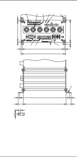
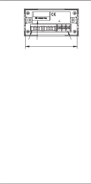
1.1.2 Name and dimensions of each part
1) EV-16P |
|
|
|
|
|
|
|
Unit: mm |
|
1 |
5 |
2 |
3 |
|
4 |
10 11 |
|
4 |
IN |
RS LINK |
|
|
|
|
|
|
|
OUT |
Err. |
|
|
|
|
|
|
|
|
|
5 |
4 |
|
|
|
|
|
|
|
LOAD 8 7 MODE 6 |
3 |
SEL. 2 1 |
DATA |
|
|
F |
E |
D |
INPUT |
C |
|
B |
A |
|
|
|
|
||||||
64 |
|
|
|
|
|
|
|
72 |
|
RS-232C |
IO/BCD |
|
|
+V |
-V |
|
|
|
|
|
|
|
|
|
|
|
|
|
|
Code No.***-*** |
Model EV-16P |
|
DC12-24V |
|
|
4 |
|
|
Code No.***-*** |
|
|
|||
|
|
|
|
|
700mA |
|
||
|
|
|
|
|
|
|
6 |
|
|
|
|
|
|
|
|
|
|
4 |
6 |
7 |
136 |
9 |
|
|
8 |
4 |
|
|
|
|
|
|
|||
|
|
|
144 |
|
|
|
|
|
11, 12
5 |
161 |
5 |
16 |
139 |
16 |
6.5 |
4.5 |
1. RS LINK connector |
2. Error LED |
3.Parameter input switch (4 pieces)
4.Parameter LED (8 pieces)
5.Gage input connector (INPUT A - F)
6. |
RS-232C connector |
7. |
I/O connector |
8. |
Power inlet terminal strip |
9. |
Name plate |
10.Junction bracket*
11.M4 x 8 screw*
12.Fixing leg*
* Standard accessory
1 - 2 |
No. 99MBC034B |
1 OVERVIEW
2) EV-16D |
|
|
|
|
|
|
|
|
|
|
|
Unit: mm |
|
1 |
|
|
|
2 |
3 |
|
4 |
5 |
|
10 11 |
|
4 |
IN |
RS LINK |
OUT |
|
|
5 |
4 |
|
|
|
|
|
|
|
Err. |
LOAD |
8 7 MODE 6 |
3 |
SEL. 2 1 |
DATA |
|
|
|||
|
|
|
|
|
|
|||||||
|
|
|
|
|
|
INPUT |
|
|
|
|
|
|
|
|
|
|
F |
E |
D |
|
C |
|
B |
A |
|
64 |
|
|
|
|
|
|
|
|
|
|
|
72 |
|
RS-232C |
|
IO/BCD |
|
|
|
+V |
-V |
|
|
||
|
|
|
|
|
|
|
|
|
|
|
||
|
|
|
D |
|
Code No.***-*** |
Model EV-16D |
|
DC12-24V |
|
|
||
|
|
|
|
Code No.***-*** |
|
|
|
|
||||
4 |
|
|
|
|
|
700mA |
|
|
||||
|
|
|
|
|
|
|
|
|
|
|
6 |
|
|
|
|
|
|
|
|
|
|
|
|
|
|
4 |
6 |
7 |
|
136 |
|
9 |
|
|
|
8 |
4 |
|
|
|
|
|
|
|
|
|
|
||||
|
|
|
|
144 |
|
|
|
|
|
|
|
|
11, 12
5 |
161 |
5 |
16 |
139 |
16 |
6.5 |
4.5 |
1. RS LINK connector |
2. Error LED |
3.Parameter input switch (4 pieces)
4.Parameter LED (8 pieces)
5.Gage input connector (INPUT A - F)
6. |
RS-232C connector |
7. |
I/O connector |
8. |
Power inlet terminal strip |
9. |
Name plate |
10.Junction bracket*
11.M4 x 8 screw*
12.Fixing leg*
* Standard accessory
No. 99MBC034B |
1 - 3 |

3) EV-16Z |
|
|
|
|
Unit: mm |
1 |
5 |
2 |
3 |
4 |
10 11 |
4 |
|
|
|
|
|
64 |
|
|
|
|
72 |
4 |
|
|
|
|
6 |
|
|
|
|
9 |
|
6 |
7 |
|
|
8 |
|
|
|
|
4 |
||
4 |
|
136 |
|
|
|
|
|
|
|
||
|
|
144 |
|
|
|
11, 12
5 |
161 |
5 |
16 |
139 |
16 |
6.5 |
4.5 |
1. RS LINK connector |
2. Error LED |
3.Parameter input switch (4 pieces)
4.Parameter LED (8 pieces)
5.Gage input connector (INPUT A - F)
6. |
RS-232C connector |
7. |
I/O connector |
8. |
Power inlet terminal strip |
9. |
Name plate |
10.Junction bracket*
11.M4 x 8 screw*
12.Fixing leg*
* Standard accessory
1 - 4 |
No. 99MBC034B |
1 OVERVIEW
1.2 D-EV External Display Unit (optional)
1.2.1 Features
The D-EV External Display Unit is an optional product used to set the measurement conditions (parameters) and externally display EV Counter measurements.
A single D-EV can display/set up one EV Counter.
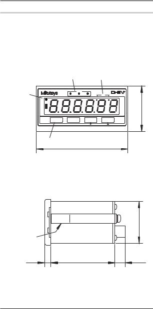
1.2.2Name and dimensions of each part
1)D-EV appearance (front view)
|
2 |
|
3 |
1 |
|
GAGE |
|
|
|
TIR |
|
UNIT |
|
MAX |
MIN |
|
|
+NG |
|
|
|
|
GO |
|
|
|
-NG |
DISP |
Fn |
MODE |
P.SET |
4
96
1.UNIT LED
2.GAGE No. LED
3.Peak mode LED
4.Key switch
Unit: mm
48
2) D-EV appearance (side view) |
Unit: mm |
|
44.4 |
5 |
|
|
6.6 |
67 |
(11) |
5. Panel-mounting bracket
No. 99MBC034B |
1 - 5 |
3) D-EV appearance (rear view) |
Unit: mm |
Code No. |
02ADD400 |
Model |
D-EV |
Serial No. |
000001 |
DC12-24V
MADE IN JAPAN
200mA
IN RS LINK OUT  +V -V
+V -V
6 |
7 |
8 |
|
|
91.4 |
6.RS LINK connector
7.Name plate
8.Power inlet terminal strip
1 - 6 |
No. 99MBC034B |
1 OVERVIEW
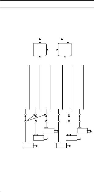
1.3 Internal Block Diagram
|
|
|
|
|
|
|
|
CEL designation Peak mode switching |
Zero-setting |
Presetting Peak clear |
Tolerance value input |
|
|
I/O output Tolerance judgment output |
Segment output |
BCD output |
|
CEL designation |
|
|
|
|
|
|
|
|
|
|
|||||||||||
|
|
|
|
|
|
|
Output function |
|
|
|
|
|
|
|
Simultaneously |
|
|
|
|
|
|
|
|
|
|
|
|
|
|
|
|
|
|
||||||
|
|
|
|
|
|
|
|
|
|
|
|
|
|
|
|
|
|
|
|
|
|
|
|
|
|
|
|
|
|
|
|
|
|||||||
|
|
|
|
|
|
|
|
|
RS-232C |
|
|
|
|
|
|
|
Tolerance |
judgment |
Segment |
BCD |
|
|
|
|
|
|
|
|
Calculation |
|
|||||||||
|
|
|
|
|
|
|
|
|
|
|
|
|
|
|
|
|
|
|
|
|
|
|
|
||||||||||||||||
|
|
|
|
|
|
|
|
|
|
|
|
|
|
|
|
|
|
|
|
|
|
|
|
|
|
|
|
|
|
|
|
|
|
|
|
|
|
||
|
|
|
|
|
|
|
|
|
|
|
|
|
|
|
|
|
|
|
|
|
|
|
|
|
|
|
|
|
|
|
|
|
|
|
|||||
|
|
|
|
|
|
|
|
|
|
|
|
|
|
|
|
|
|
|
|
|
|
|
|
|
|
|
|
|
|
|
|
|
|
|
|
|
|
|
|
|
|
|
|
|
|
|
|
|
|
|
|
|
|
|
|
|
|
|
|
|
|
|
|
|
|
|
|
|
|
|
|
|
|
|
|
|
|
|
|
counter |
Calculation |
mode |
|
Sum of CELs |
|
Mean of CELs |
|
|
Maximum of |
CELs |
|
|
Minimum of |
CELs |
|
|
|
|
MAX - MIN of CELs |
|
|
Calculation result Tolerance judgment |
|
|
function |
||||||||||||||
|
|
|
|
|
|
|
|
|
|
|
|
|
|
|
|||||||||||||||||||||||||
|
|
|
|
|
|
|
|
|
|
|
|
|
|
|
|
|
|
|
|
|
|
|
|
|
|
|
|
|
|
|
|
|
|
|
|
|
|
|
|
Internal |
|
|
|
|
|
|
|
|
|
|
|
|
|
|
|
|
|
|
|
|
|
|
|
|
|
|
|
|
|
|
|
|
|
|
|
counterInternal |
|
||
NORMALmode |
High-speed mode |
|
CEL1 tolerancesetup |
Peakmeasurement |
CEL2 tolerancesetup |
Peakmeasurement |
|
|
CEL3 tolerancesetup Peakmeasurement |
|
CEL4Origin and tolerancesetup Peakmeasurement |
|
CEL5Origin and |
tolerancesetup Peakmeasurement |
|
|
CEL6 tolerancesetup |
Peakmeasurement |
|
|
|||||||||||||||||||
|
|
|
|
Originand |
|
|
Originand |
|
|
|
|
Originand |
|
|
|
|
|
|
|
|
|
|
|
|
|
|
|
|
Originand |
|
|
|
|
|
|
|
|||
|
|
|
|
|
|
|
|
|
|
|
|
|
|
|
|
|
|
|
|
|
|
|
|
|
|
|
|
|
|
|
|
|
|
|
|
|
|
Gage |
selector |
|
|
|
|
|
|
|
|
|
|
|
|
|
|
|
|
|
|
|
|
|
|
|
|
|
|
|
|
|
|
|
|
|
|
|
|
|
|
||
|
|
|
|
|
|
|
|
|
|
|
|
|
|
|
|
|
|
|
|
|
|
|
|
|
|
|
|
|
|
|
|
|
|
|
|
|
|
||
|
Gage |
selector |
|
|
|
|
|
|
|
|
|
|
|
|
|
|
|
|
|
|
|
|
|
|
|
|
|
|
|
|
|
|
|
|
|
|
|
||
|
|
|
|
|
|
|
|
|
|
|
|
|
|
|
|
|
|
|
|
|
|
|
|
|
|
|
|
|
|
|
|
|
|
|
|
||||
|
|
|
|
|
|
|
Gage B |
|
|
Gage C |
|
|
|
|
|
|
|
|
|
|
|
Gage E |
|
|
|
Gage F |
|
|
|
|
|
|
|
||||||
|
|
|
Gage A |
|
|
|
|
|
|
|
|
|
Gage D |
|
|
|
|
|
|
|
|
|
|
|
|
|
|
|
|
|
|||||||||
|
|
|
|
|
|
|
|
|
|
|
|
|
|
|
|
|
|
|
|
|
|
|
|
|
|
|
|
|
|
|
|
|
|
||||||
Gage selector:
By setting the appropriate parameters it is possible to connect a single gage output either to one internal counter or to multiple internal counters. With this function, multiple origins and tolerance setups can be set for a single gage.
Internal counter:
Origin setup, peak measurement, and tolerance setup can be performed individually for each of the six internal counters (CEL1 - CEL6).
No. 99MBC034B |
1 - 7 |

Calculation function:
Each of the internal counters has a specific calculation function. Therefore, calculation can be performed between the counters specified by the parameters.
Output function:
Either RS-232C, BCD, tolerance judgment, or segment output can be selected. The objective CEL to be output can be selected using the RS-232C command or SET signal.
1 - 8 |
No. 99MBC034B |
2 |
SETUP |
This chapter describes the method used to in- |
|
stall and connect the EV Counter and make its |
|
initial conditions. |
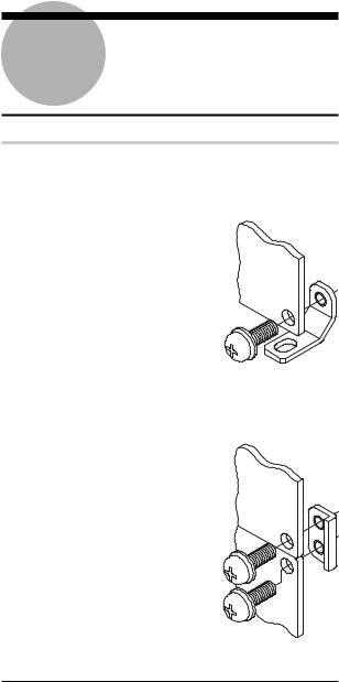
2.1 Installing the EV Counter
Both the front and rear panels of the EV Counter have four mounting holes. Use the fixing legs and junction brackets which come as the standard accessories to install the EV Counter.
a) The fixing legs
(1)Attach the fixing legs (4 places) on the counter main unit using the supplied screws.
(2)Use the oval hole provided on each fixing leg to secure the counter to
an appropriate surface.
b) The junction brackets
Use the junction brackets and supplied screws to join the two panels along the vertical.
No. 99MBC034B |
2 - 1 |

2.2 Connecting Cables
IMPORTANT • Connection should be made only after the power to the main unit and to the partner device of the connection have been turned off. Otherwise, the counter main unit and the connected device will be damaged.
•Use a 12 - 24VDC power supply with a control output current of 1A or greater. Do not draw power from a source which is used by highpower equipment.
•Do not route the power cable, I/O cable, RS-
232C cable, RS LINK cable, or gage connection cable with other power cables.
•Use a shielded I/O cable not longer than 3m.
•Always ground.
•Each cable should be secured (to, for example, the main body of the device).
2.2.1Connecting gages
(1)Sequentially connect the required number of linear gages to the corresponding connectors, starting with the INPUT A connector.
(2)If the EV-16P or EV-16Z is connected to a gage that does not have a resolution of 1 m, refer to section 3.1 Setting Parameters (with D-EV) and section 3.2 Setting Parameters (with EV Counter) to adjust the resolution.
NOTE • The gage resolution has been factory-set to 1mm.
•It is not necessary to modify the resolution on the EV-
16D.
(3)Set the parameter for designating available axes according to the number of gages to be connected.
(Refer to section 3.1 Setting Parameters (with D-EV) and section 3.2 Setting Parameters (with EV Counter)).
2 - 2 |
No. 99MBC034B |
2 SETUP
2.2.2 Connecting the D-EV (External Display Unit)
If a D-EV (External Display Unit) is used, make the necessary connections according to the following procedure.
(1)Connect the RS LINK OUT connector of the EV Counter to the RS LINK IN connector of the D-EV using an RS LINK connection cable.
EV Counter |
|
RS LINK |
|
|
RS LINK |
D-EV |
|||||||
|
|
IN OUT |
|
|
IN OUT |
|
|||||||
|
|
|
|
|
|
|
|
|
|
|
|
|
RS LINK |
|
RS-232C |
|
|
|
|
|
|
|
|||||
|
|
|
|
|
|
|
|
connecting |
|||||
|
|
|
|
|
|
|
|
|
|
|
|
|
|
|
|
|
|
|
|
|
|
|
|
|
|
|
cable (optional) |
|
|
|
|
|
|
|
|
|
|
|
|
|
|
|
|
|
|
|
|
|
|
|
|
|
|
|
|
NOTE Always use the RS LINK connection cable specified by
Mitutoyo. Refer to section 8.3 Optional Accessories.
(2)To link more than one counter with the RS LINK connection cables, refer to chapter 6 RS LINK FUNCTION.
TIP The D-EV will display the data of the EV Counter which is connected to the RS LINK IN connector of the D-EV.
2.2.3 RS-232C, I/O/BCD, and RS LINK connections
The EV Counter has an RS-232C connector, I/O/BCD connector, and RS LINK connector. If these connectors are used, refer to chapter 5 RS-232C COMMUNICA-
TION FUNCTION; chapter 6 RS LINK
FUNCTION; and chapter 7 I/O FUNCTION for information about cable connec-
tions.
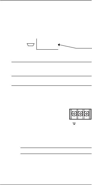
2.2.4 Connecting the power supply and grounding
The EV Counter and D-EV do not have a power switch. Power is supplied by connecting the power source to the +V and -V terminals on the power inlet terminal strip.
IMPORTANT Positively ground the grounding terminal.
No. 99MBC034B |
2 - 3 |
2.3 Power On
When the power source is connected to the EV Counter, it enters the counting stand-by state. To start operation and enter the counting state, quit the stand-by state.
TIP The counting stand-by function is an alarm function that is entered if there is a power interruption during use.
a) If a D-EV is not connected
(1)If the EV-16P or EV-16D is used,enter the RS-232C command or I/O signal (a HOLD signal to clear the error) in the EV Counter. For information refer to chapter 5 RS-232C
COMMUNICATION FUNCTION; and chapter 7 I/O FUNCTION.
(2)If the EV-16Z is used, push in the spindles of all connected gages to pass through the origins after completing the procedure (1) described above.
b) If a D-EV is connected
(1)When the EV Counter and D-EV are on, the counting standby state is entered.
[Display on the D-EV]
UNIT |
+NG |
GO
-NG
(2)-1
If the EV-16P or EV-16D is used, press the P.SET key to quit the counting stand-by state and enter the counting state.
[Display on the D-EV]
UNIT |
+NG |
|
GO |
|
-NG |
(2)-2
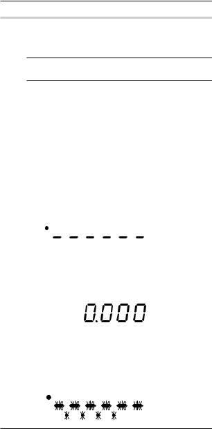
If the EV-16Z is used, press the P.SET key to cancel the counting stand-by mode, then the counter enters the origin detection wait mode. All decimal points flash in the origin detection wait mode.
[Display on the D-EV]
UNIT |
+NG |
|
GO |
|
-NG |
2 - 4 |
No. 99MBC034B |
2 SETUP
(3)If the EV-16Z is used, push in the spindle of the connected gages to pass through the origin one after another, and each time it passes through the origin the corresponding bar display of the CH starts flashing.
[Display on the D-EV]
UNIT |
+NG |
|
GO |
|
-NG |
(4)If the EV-16Z is used, push in the spindles of all connected gages to pass through the origins, then the counter enters the counting mode.
[Display on the D-EV]
UNIT |
+NG |
GO
-NG
c)Precautions in using the EV-16Z
If the EV-16Z is used, note the following precautions.
IMPORTANT Be sure to pass the spindle through the origin for detection properly. If the spindle vibrates near the origin, the origin may not be detected correctly.
TIP • The origin-embedded gage has a specific origin inside the gage. When the spindle passes through the origin the signal generates, then the preset position is restored.
•Origin detection is usually performed when the power is turned on. If the origin re-detection parameter
(P.No.42) is set to 1, the counter enters the origin detection wait mode after completing preset or tolerance setup (for details, refer to the section, “3.1 Setting
Parameters (with D-EV)”), or when the HOLD signal is triggered.
•If the HOLD signal is input again during origin re-de- tection, the counter resets origin re-detection, except when resetting an error.
No. 99MBC034B |
2 - 5 |

3 |
SETTING PARAMETERS |
This chapter describes the method used to set |
|
the parameters required to use the EV |
|
Counter. |
3.1 Setting Parameters (with D-EV)
Before using the EV Counter, various parameters must be set up. This section explains the setup method using the essential parameters, "gage resolution" (for EV-16P and EV-16Z) and "designation of available axes", as examples.
NOTE For the resolution of 0.1 m setting, a D-EV is absolutely necessary.
3.1.1 Parameter mode ON
Set the parameter mode to ON to modify the existing parameter settings.
(1)Press the P.SET key while holding down the Fn key to set the parameter mode to ON.
[Display on the D-EV]
UNIT |
+NG |
|
GO |
|
-NG |
(2)Press the P.SET key one more time to modify the setup value to 1.
[Display on the D-EV]
UNIT |
+NG |
GO
-NG
NOTE If a parameter setting needs to be modified, first modify the setting of Parameter 00 to 1. Parameter modification cannot be attempted while the setting of Parameter 00 is 0 (Reference mode).
(3) Begin setting the parameters.
No. 99MBC034B |
3 - 1 |
 Loading...