


No.99MBC071A1
SERIES No.544
LSM-6900
Laser Scan
Micrometer
(Display Unit)
User's Manual
Read this User’s Manual thoroughly before operating the instrument. After reading,
retain it close at hand for future reference.

CONVENTIONS USED IN USER'S MANUAL
Safety Precautions
To operate the instrument correctly and safely, Mitutoyo manuals use various safety signs (Signal Words and Safety Alert Symbols) to identify and warn against hazards and potential accidents.
The following signs indicate general warnings:
Indicates an imminently hazardous situation which, if not avoided, will result in serious
injury or death.
DANGER
Indicates a potentially hazardous situation which, if not avoided, could result in serious
injury or death.
WARNING
Indicates a potentially hazardous situation which, if not avoided, may result in minor or
moderate injury or property damage.
CAUTION
The following signs indicate specific warnings or prohibited actions, or indicate a mandatory action:
Alerts the user to a specific hazardous situation. The given example means “Caution, risk of electric shock”.
Prohibits a specific action. The given example means “ Do not disassemble”.
Specifies a required action. The given example means “Ground”.
i |
No. 99MBC071A |

CONVENTIONS USED IN USER'S MANUAL
On Various Types of Notes
The following types of notes are provided to help the operator obtain reliable measurement data
through correct instrument operation.
IMPORTANT • An important note is a type of note that provides information essential to the completion
of a task. You cannot disregard this note to complete the task.
•An important note is a type of precaution, which if neglected could result in a loss of data, decreased accuracy or instrument malfunction/failure.
NOTE A note emphasizes or supplements important points of the main text. A note supplies information that may only apply in special cases (e.g.. Memory limitations, equipment configurations, or details that apply to specific versions of a program).
TIP A tip is a type of note that helps the user apply the techniques and procedures described in the text to their specific needs.
It also provides reference information associated with the topic being discussed.
Mitutoyo assumes no liability to any party for any loss or damage, direct or indirect, caused by use of this instrument not conforming to this manual.
Information in this document is subject to change without notice.
© Copyright Mitutoyo Corporation 2002. All rights reserved.
NOTES FOR EXPORTING
IMPORTANT For exporting this product, be sure to contact our office.
No. 99MBC071A |
ii |
PRECAUTIONS
1.Safety Precautions
The Measuring Unit connected to the Display Unit uses a very low power laser.
Use of controls or adjustments or performance of procedures other than those specified herein may result in hazardous radiation exposure.
CAUTION
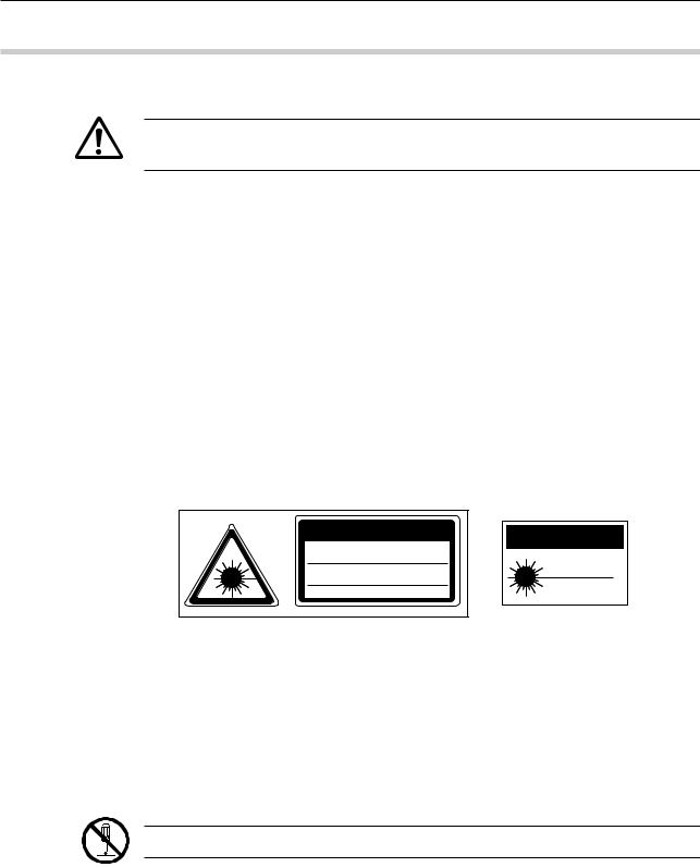
1)The IEC standard provides for two classes of laser product: a Class 2 laser product uses a visible laser (maximum power: 1.5 mW for scanning; laser device: semiconductor laser; wavelength: 650 nm).
2)Do not look directly into the laser beam. (Even if it seems that no light is being emitted from the emission window, do not look into it.)
3)Do not stare the laser beam directly through optical instrument, such as a magnifying lens.
4)If measuring flat objects with mirror finishes, avoid looking at the reflection on the surface.
5)Close the beam shutter when the instrument is not in use.
6)Do not remove the laser class identification labels attached to the Measuring Unit.
7)Before using this unit, carefully read the “Measuring Unit Specifications” and “Precautions on Use of Laser” sections provided in the manual supplied with the Measuring Unit.
CAUTION |
CAUTION |
|
LASER RADIATION-DO NOT |
|
|
STARE INTO BEAM |
LASER LIGHT-DO NOT |
|
1.5mW(peak) SCANNING LASER |
STARE INTO BEAM |
|
|
||
SEMICONDUCTOR LASER 650nm |
1mW-650nm |
|
CLASS 2 LASER PRODUCT |
||
CLASS II LASER PRODUCT |
||
IEC 60825-1 (1997-09) |
|
2.Before making the connection between the Measuring Unit and the Display Unit, turn off the power. If an optional device is to be connected to this system, make sure that the optional device is also turned off.
3.Firmly tighten the screws of the cable connectors and interfaces to ensure shielding.
4.Do not touch the terminals of the connectors, otherwise contact may be poor.
5.Positively ground the Display Unit.
6.An error display may appear during operation. However, it may not always indicate a fault. If an error display appears, consult the “Maintenance and Inspection” section.
Do not open the covers provided on the emission unit and reception unit.
iii |
No. 99MBC071A |

INSTALLING CONDITIONS
The Mitutoyo Laser Scan Micrometer is both a precision optical instrument and a precision electronic instrument and this unit is the instrument suitable for indoor use as well. Therefore, it must be carefully installed and the following conditions must be taken into consideration to attain the highest possible accuracy.
1.Vibration
Install this unit if possible in a place where it will not be subject to vibration. If this unit is used for a long period of time in an environment where there are significant vibrations, the precision parts in this unit may be affected, resulting in the deterioration of measuring accuracy.
If this unit has to be used in an environment where vibration is significant, measures such as the laying of a vibration damping rubber pad under the unit must be applied to reduce the effect of vibration.
2.Dust
Dust and airborne particles at the installation site adversely affect optical parts including the protective glass and electronic parts of the Measuring Unit. Place this unit in a place with as little dust and as few airborne particles as possible.
3.Direct sunlight
If this unit is subjected to direct sunlight, the heat may deform this unit and affect the measuring accuracy.
If this unit must be placed by a window where it will be subjected to direct sunlight, protect the unit by shading it.
4.Ambient temperature and humidity
This unit must be operated in an environment where the temperature is between 0 and 40˚C and the humidity is between 35 and 85% RH. Avoid installing this unit where there is significant temperature or humidity change.
Significant temperature and humidity changes may reduce measuring accuracy.
WARRANTY
In the event that the Mitutoyo Laser Scan Micrometer (LSM) should prove defective in workmanship or material, within one year from the date of original purchase for use, it will be repaired or replaced, at our option, free of charge upon its prepaid return to us.
If the unit fails or is damaged because of the following causes it will be subject to a repair change, even if it is still under warranty.
1.Failure or damage due to inappropriate handling or unauthorized modification.
2.Failure or damage due to transport, droppage, or relocation of the machine after purchase.
3.Failure or damage due to fire, salt, gas, abnormal voltage, or natural catastrophe.
This warranty is effective only where the machine is properly installed and operated following this manual.
No. 99MBC071A |
iv |

CONTENTS
CONVENTIONS USED IN USER'S MANUAL ................................................................. |
i |
||||
NOTES FOR EXPORTING ............................................................................................... |
ii |
||||
PRECAUTIONS ............................................................................................................... |
|
|
iii |
||
INSTALLING CONDITIONS ........................................................................................... |
iv |
||||
WARRANTY .................................................................................................................... |
|
|
iv |
||
1. |
INTRODUCTION ................................................................................................... |
|
1-1 |
||
|
1.1 |
Outline ........................................................................................................... |
|
|
1-1 |
|
1.2 |
Foreword ....................................................................................................... |
|
1-1 |
|
|
1.3 |
Nomenclature |
................................................................................................ |
1-2 |
|
|
|
1.3.1 |
Display Unit ....................................................................................... |
1-2 |
|
|
|
1.3.2 |
Measuring Unit .................................................................................. |
1-4 |
|
2. |
SETUP .................................................................................................................. |
|
|
2-1 |
|
|
2.1 Unpacking and Acceptance Check ............................................................... |
2-1 |
|||
|
2.2 |
Connecting the Cables ................................................................................. |
2-1 |
||
|
2.3 |
Preliminary Checks ....................................................................................... |
2-5 |
||
|
2.4 Initializing the LSM-6900 Display Unit .......................................................... |
2-6 |
|||
3. DISPLAYS AND KEY OPERATIONS .................................................................. |
3-1 |
||||
|
3.1 Outline of the Operation Modes ................................................................... |
3-1 |
|||
|
|
3.1.1 |
Measurement Principle ..................................................................... |
3-1 |
|
|
|
3.1.1.1 |
Overview ................................................................................. |
3-1 |
|
|
|
3.1.1.2 |
Setting the segment ............................................................... |
3-3 |
|
|
|
3.1.1.3 Measurement interval (measurement time) ........................... |
3-4 |
||
|
|
3.1.2 |
Outline of the Operation Modes ....................................................... |
3-5 |
|
|
|
3.1.2.1 |
Basic setup mode ................................................................... |
3-6 |
|
|
|
3.1.2.2 |
Calibration mode .................................................................... |
3-6 |
|
|
|
3.1.2.3 Measuring condition setup mode ........................................... |
3-6 |
||
|
|
3.1.2.4 |
Other setup mode ................................................................... |
3-6 |
|
|
|
3.1.2.5 |
Statistic display mode ............................................................. |
3-6 |
|
|
|
3.1.2.6 |
Measurement mode ................................................................ |
3-7 |
|
|
3.2 Techniques and Terminology of Setup Functions ........................................ |
3-9 |
|||
|
|
3.2.1 |
Program ............................................................................................ |
3-9 |
|
|
|
3.2.2 |
Basic setup ....................................................................................... |
3-9 |
|
|
|
3.2.3 |
Function setup ................................................................................ |
3-10 |
|
|
|
3.2.4 |
Setups according to the property of each workpiece ..................... |
3-10 |
|
|
|
3.2.4.1 Transparent object (Workpiece that transmits light) ............ |
3-10 |
||
|
|
3.2.5 |
Latch (holding) of the displayed value ........................................... |
3-10 |
|
|
|
3.2.6 |
Automatic measurement with an edge specification ...................... |
3-11 |
|
|
|
3.2.7 |
GO/NG judgment ............................................................................ |
3-12 |
|
|
|
3.2.8 |
Abnormal data elimination .............................................................. |
3-14 |
|
|
|
3.2.9 |
Offset/Zero-set ................................................................................ |
3-15 |
|
|
|
3.2.10 |
Mastering ........................................................................................ |
3-16 |
|
|
|
3.2.11 |
Reference value .............................................................................. |
3-16 |
|
|
|
3.2.12 |
Data output conditions .................................................................... |
3-17 |
|
|
|
3.2.13 |
Automatic workpiece detection <Diameter detection method, |
|
|
|
|
|
Position detection method> ............................................................ |
3-17 |
|
|
|
3.2.14 |
Group judgment .............................................................................. |
3-20 |
|
|
|
3.2.15 |
Recording the amount of light ........................................................ |
3-21 |
|
v |
No. 99MBC071A |

3.3 Outline of the Display Contents .................................................................. |
3-22 |
||
3.3.1 |
Display unit ..................................................................................... |
3-22 |
|
3.3.2 |
Data display unit ............................................................................. |
3-22 |
|
3.4 Outline of Key Operations .......................................................................... |
3-24 |
||
3.4.1 Description of key functions ........................................................... |
3-25 |
||
3.4.2 |
Example key operations ................................................................. |
3-29 |
|
4. SETTING UP THE MEASURING CONDITIONS ................................................. |
4-1 |
||
4.1 Basic Setup ................................................................................................... |
|
4-1 |
|
4.1.1 Outline of the basic setup procedure ............................................... |
4-2 |
||
4.1.2 Description of each mode ................................................................. |
4-3 |
||
|
4.1.2.1 Selecting and setting the function in the B0 mode. ............... |
4-4 |
|
|
a. Setting the resolution (Guidance: RES) ............................ |
4-4 |
|
|
b. Setting the number of blank-out digits (Guidance: BLN) .. |
4-5 |
|
|
c. Putting a comma after the thousandths digits |
|
|
|
|
(Guidance: (,)) ................................................................... |
4-5 |
|
d. Setting the buzzer function (Guidance: BUZZER) ............ |
4-6 |
|
|
e. Setting the display latch timer (Guidance: LATCH) .......... |
4-6 |
|
|
4.1.2.2 Selecting and setting the function in the B1 mode. ............... |
4-7 |
|
|
a. Setting the output function in the ready state |
|
|
|
|
(Guidance: D.OUT)............................................................ |
4-7 |
|
b. Setting the analog output voltage if Err-0 occurs |
|
|
|
|
(Guidance: ERR-0 V) ........................................................ |
4-7 |
|
c. Selecting the display message if Err-0 occurs |
|
|
|
|
(Guidance: ERR-0 D) ........................................................ |
4-7 |
|
d. Selecting the display message at the start of measurement |
||
|
|
(Guidance: RUN D) ........................................................... |
4-8 |
|
e. Selecting the averaging method (Guidance: AVG.M) ....... |
4-8 |
|
|
f. |
Setting the GO/NG judgment method |
|
|
|
(Guidance: JDG.M)............................................................ |
4-8 |
|
g. Setting whether the target value is copied to the |
|
|
|
|
reference value (Guidance: COPY) .................................. |
4-9 |
|
4.1.2.3 Selecting and setting the function in the B2 mode .............. |
4-10 |
|
|
a. Setting the workpiece type (Guidance: WORK.P) .......... |
4-10 |
|
|
b. Setting the simultaneous measurement |
|
|
|
|
(Guidance: PROG) .......................................................... |
4-10 |
|
c. Selecting the method of specifying segments |
|
|
|
|
(Guidance: SEG) ............................................................. |
4-11 |
|
4.1.2.4 Selecting and setting the function in the B3 mode .............. |
4-12 |
|
|
a. Setting the abnormal value elimination function |
|
|
|
|
(Guidance: ADE) ............................................................. |
4-12 |
|
b. Setting the automatic workpiece detecting function |
|
|
|
|
(Guidance: AWDT) .......................................................... |
4-12 |
|
c. Setting the number of scans (Guidance: SCAN) ............ |
4-12 |
|
|
d. Setting the group judgment (Guidance: GTJ) ................. |
4-13 |
|
|
e. Setting the group judgment output (Guidance: GTJ D) .. |
4-13 |
|
No. 99MBC071A |
vi |

4.1.2.5 Selecting and setting the function in the B4 mode .............. |
4-14 |
a.Setting the use of RS-232C port (Guidance: RS-232C) . 4-14
b.Setting the RS-232C communication baud rate
|
|
|
(Guidance: BAUD) ........................................................... |
4-14 |
|
|
|
c. Setting the RS-232C communication data bits |
|
|
|
|
(Guidance: LENGTH) ...................................................... |
4-14 |
|
|
|
d. Setting the RS-232C communication parity bit |
|
|
|
|
(Guidance: PARITY) ........................................................ |
4-15 |
|
|
|
e. Setting the delimiter for communication |
|
|
|
|
(Guidance: DELIMT)........................................................ |
4-15 |
|
|
|
f. Setting the RS-232C line control |
|
|
|
|
(Guidance: CONTRL) ...................................................... |
4-15 |
|
|
4.1.2.6 |
Selecting and setting the function in the B5 mode .............. |
4-16 |
|
|
|
a. Setting the RUN input function from the I/O interface |
|
|
|
|
(Guidance: RUN) ............................................................. |
4-16 |
|
|
|
b. Setting the OFFS input function from the I/O interface |
|
|
|
|
(Guidance: OFFS) ........................................................... |
4-16 |
|
|
|
c. Setting the GO output function from the I/O interface |
|
|
|
|
(Guidance: GO) ............................................................... |
4-17 |
|
|
4.1.2.7 |
Selecting and setting the function in the B6 mode .............. |
4-17 |
|
|
|
a. Setting the use of DCU (Guidance: DCU) ...................... |
4-17 |
4.2 |
Calibration ................................................................................................... |
|
4-18 |
|
|
4.2.1 Calibration gages and gage stand ................................................. |
4-18 |
||
|
4.2.2 Entering the calibration mode ......................................................... |
4-18 |
||
4.3 Positioning a Gage or a Workpiece ............................................................ |
4-22 |
|||
4.4 How to read-in the amount of light ............................................................. |
4-22 |
|||
4.5 Setting Up the Functions ............................................................................ |
4-23 |
|||
|
4.5.1 Outline of the function setup mode ................................................ |
4-23 |
||
|
4.5.2 Outline of each function setup mode ............................................. |
4-25 |
||
|
4.5.3 |
Function setup mode ...................................................................... |
4-26 |
|
|
|
4.5.3.1 |
F0: Setting the segment ....................................................... |
4-26 |
|
|
4.5.3.2 |
F1: Setting the measurement interval (measurement time) |
4-28 |
|
|
4.5.3.3 |
F2: Setting the GO/NG judgment criteria ............................. |
4-30 |
|
|
4.5.3.4 |
F3: Setting the reference value ............................................ |
4-34 |
|
|
4.5.3.5 |
Analog voltage output and scale value ................................ |
4-35 |
|
|
4.5.3.6 |
F4: Setting the offset value .................................................. |
4-37 |
|
|
4.5.3.7 |
F5: Setting the data output conditions ................................. |
4-39 |
|
|
4.5.3.8 |
F6: Setting the sample measurement .................................. |
4-40 |
|
|
4.5.3.9 |
F7: Automatic workpiece detection setting .......................... |
4-41 |
|
|
4.5.3.10 |
F8: Setting the group judgment ............................................ |
4-42 |
|
|
4.5.3.11 |
Confirming the function setup contents ................................ |
4-43 |
5. MEASUREMENT MODE ...................................................................................... |
5-1 |
|||
5.1 Outline of the Measurement Mode ............................................................... |
5-1 |
|||
|
5.1.1 Settings made in the measurement mode ....................................... |
5-1 |
||
|
|
5.1.1.1 |
Setup operation from the arrow key ....................................... |
5-2 |
|
|
5.1.1.2 |
Setup that can be made directly from each setup item key .. |
5-4 |
5.2 |
Other Functions ............................................................................................ |
5-5 |
||
|
5.2.1 |
Key lock ............................................................................................ |
5-5 |
|
|
5.2.2 Displaying the measuring position .................................................... |
5-5 |
||
vii |
No. 99MBC071A |

5.3 |
Applied Measurement ................................................................................... |
5-6 |
||
|
5.3.1 Diameter measurement of a precision-machined workpiece ........... |
5-6 |
||
|
5.3.2 Measurement of the lead pitch of a multiple-pin IC ......................... |
5-7 |
||
|
5.3.3 Applied Measurement with Offset/Zero-Set Functions ..................... |
5-9 |
||
|
5.3.4 |
Sample measurement ..................................................................... |
5-12 |
|
|
5.3.5 Applied measurement with automatic workpiece detection ........... |
5-14 |
||
|
5.3.6 Applied measurement on a stepped round bar .............................. |
5-16 |
||
6. INTERFACE UNIT |
................................................................................................ |
6-1 |
||
6.1 |
Standard Interface ........................................................................................ |
6-1 |
||
|
6.1.1 |
I/O Analog Interface .......................................................................... |
6-1 |
|
|
|
6.1.1.1 |
External view of the connector ............................................... |
6-1 |
|
|
6.1.1.2 |
Terminal names ...................................................................... |
6-2 |
|
|
6.1.1.3 |
Input/output equivalent circuit ................................................. |
6-2 |
|
|
6.1.1.4 |
Timing chart ............................................................................ |
6-5 |
|
6.1.2 |
RS-232C Interface ............................................................................ |
6-7 |
|
|
|
6.1.2.1 |
Specifications .......................................................................... |
6-7 |
|
|
6.1.2.2 |
Connections ............................................................................ |
6-8 |
|
|
6.1.2.3 |
Printer interface .................................................................... |
6-10 |
|
|
6.1.2.4 |
RS-232C/GP-IB commands ................................................. |
6-10 |
|
|
6.1.2.5 |
List of commands ................................................................. |
6-12 |
|
|
6.1.2.6 |
List of response commands if an error occurs .................... |
6-14 |
|
|
6.1.2.7 |
Format of response commands ........................................... |
6-15 |
|
|
6.1.2.8 |
Other commands .................................................................. |
6-16 |
|
|
6.1.2.9 |
Details of command descriptions ......................................... |
6-17 |
|
|
6.1.2.10 |
An example Program of RS-232C Communication ............. |
6-25 |
|
|
6.1.2.11 An example Program of GP-IB Communication Control ..... |
6-26 |
|
6.2 |
Optional Interface ........................................................................................ |
6-27 |
||
|
6.2.1 Digimatic Output Unit interface ....................................................... |
6-27 |
||
|
|
6.2.1.1 |
Method of use ....................................................................... |
6-27 |
|
|
6.2.1.2 |
Name of each part ................................................................ |
6-28 |
|
|
6.2.1.3 |
I/O specifications .................................................................. |
6-29 |
|
|
6.2.1.4 |
Timing chart .......................................................................... |
6-30 |
|
|
6.2.1.5 |
Data format ........................................................................... |
6-31 |
|
6.2.2 Second Analog I/O Interface .......................................................... |
6-33 |
||
|
|
6.2.2.1 |
Method of use ....................................................................... |
6-33 |
|
|
6.2.2.2 |
Name of each part ................................................................ |
6-33 |
|
|
6.2.2.3 |
I/O Interface .......................................................................... |
6-34 |
|
|
6.2.2.4 |
Analog output ....................................................................... |
6-43 |
|
6.2.3 |
BCD interface ................................................................................. |
6-44 |
|
|
|
6.2.3.1 |
Method of use ....................................................................... |
6-44 |
|
|
6.2.3.2 |
Name of each part ................................................................ |
6-44 |
|
|
6.2.3.3 |
Specification ......................................................................... |
6-45 |
|
6.2.4 |
GP-IB interface ............................................................................... |
6-49 |
|
|
|
6.2.4.1 |
Method of use ....................................................................... |
6-49 |
|
|
6.2.4.2 |
Name of each part ................................................................ |
6-49 |
|
|
6.2.4.3 |
Specification ......................................................................... |
6-50 |
|
|
6.2.4.4 |
Functions .............................................................................. |
6-52 |
|
|
6.2.4.5 |
Operations ............................................................................ |
6-53 |
No. 99MBC071A |
viii |

|
6.3 |
Installing the Optional Interface Unit .......................................................... |
6-54 |
|
|
|
6.3.1 |
Digimatic Output Unit ...................................................................... |
6-55 |
|
|
6.3.2 Second Analog I/O, BCD, and GP-IB interfaces ............................ |
6-55 |
|
7. |
INSPECTION AND MAINTENANCE .................................................................... |
7-1 |
||
|
7.1 |
Display Unit ................................................................................................... |
7-1 |
|
|
|
7.1.1 |
Display check .................................................................................... |
7-1 |
|
|
7.1.2 |
Cleaning method ............................................................................... |
7-1 |
|
7.2 |
Measuring Unit .............................................................................................. |
7-2 |
|
|
|
7.2.1 Laser emission status indicator LED ................................................ |
7-2 |
|
|
|
7.2.2 |
Cleaning optical parts ....................................................................... |
7-2 |
|
|
7.2.3 Replacement of protection glass ...................................................... |
7-3 |
|
|
7.3 |
Error Messages and Remedies .................................................................... |
7-4 |
|
|
7.4 |
Troubleshooting and Remedies .................................................................... |
7-5 |
|
|
7.5 |
Fuse replacement ......................................................................................... |
7-6 |
|
8. |
SPECIFICATIONS (DISPLAY UNIT) ................................................................... |
8-1 |
||
|
8.1 |
LSM-6900 Display Unit ................................................................................. |
8-1 |
|
9.RESTRICTIONS ASSOCIATED WITH THE COMBINATION OF FUNCTIONS,
TABLES OF THE BASIC SETUP MODES ......................................................... |
9-1 |
|
9.1 |
Restrictions Associated with the Particular Combination of Functions ........ |
9-1 |
9.2 |
List of Setup Modes ...................................................................................... |
9-3 |
|
9.2.1 List of basic setup modes ................................................................. |
9-3 |
|
9.2.2 List of calibration functions ............................................................... |
9-4 |
|
9.2.3 Reading in the amount of light ......................................................... |
9-4 |
|
9.2.4 List of function setup modes ............................................................ |
9-5 |
SERVICE NETWORK
ix |
No. 99MBC071A |
1 |
INTRODUCTION |
This chapter describes the Laser Scan Micrometer (LSM) models and |
|
nomenclature of the Display unit and the Measuring unit. |
1.1Outline
This system is an accurate, non-contact measurement system capable of measuring workpiece dimensions at a high speed using a highly directional scanning laser beam.
This non-contact optical measuring system is capable of measuring workpieces which are difficult to measure with conventional measuring instruments. It performs simple and accurate measurement of brittle or elastic objects, objects at high temperature, objects which must be kept clean, and soft objects which may be deformed and suffer dimensional changes under the measuring forces used.
1.2Foreword
The Measuring Unit LSM-902 is used for this Display Unit.
This user’s manual primarily explains the functions of the Display Unit. For information about the safety precautions, specifications, dimensions, standard accessories, and options for each Measuring Unit, refer to the user’s manual supplied with the LSM-902.
The Measuring Unit uses a laser. For safe operation, carefully read and follow the “Safety Precautions on Use of Laser” section described in the user’s manual that is
WARNING supplied with each Measuring Unit.
No. 99MBC071A |
1 - 1 |
|
1.3Nomenclature
This section gives the name of each part in the LSM system.
1.3.1Display Unit
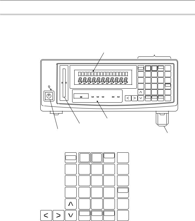
(1)Front panel
|
|
|
Data display |
|
|
Operation keys |
||||
Mitutoyo |
LASER SCAN MICROMETER |
|
LSM-6900 |
SHIFT |
RUN |
C.RUN |
S.PR |
SET |
||
|
|
|
|
|
|
|||||
|
PROG. |
|
|
|
|
|
|
|
|
|
|
|
|
|
|
|
|
|
|
|
|
|
|
|
|
|
|
READ |
7 |
8 |
9 |
C |
|
|
|
|
|
|
H.CAL |
4 |
5 |
6 |
LIMIT |
|
LOCK |
CAL |
OFFSET |
S.E |
DUAL |
L.CAL |
1 |
2 |
3 |
MASTER |
|
|
|
|
|
|
OFFSET |
||||
|
|
|
|
|
|
|
|
|
|
|
|
|
|
|
|
|
|
0 |
• |
+/- |
REF |
|
LASER EMISSION -NG |
GO |
+NG |
RUN BUSY |
|
|
LOCK |
A.CL |
STAT |
|
|
|
|
|
|
|
|
ENT |
|||
|
|
|
|
|
|
|
UNIT |
M.CL |
S.E |
|
|
|
|
|
|
|
|
|
|||
Status indicator LEDs (lit/unlit)
Workpiece position indicator LED
Power switch
Stand
(2)Displays and keys
SHIFT |
RUN |
C.RUN |
S.PR |
SET |
|
|
|
|
|
||
READ |
7 |
8 |
9 |
C |
|
H.CAL |
4 |
5 |
6 |
LIMIT |
|
L.CAL |
1 |
2 |
3 |
MASTER |
|
OFFSET |
|||||
|
|
|
|
||
|
0 |
• |
+/- |
REF |
|
|
LOCK |
A.CL |
STAT |
ENT |
|
|
UNIT |
M.CL |
S.E |
||
|
|
1 - 2 |
No. 99MBC071A |

1. INTRODUCTION
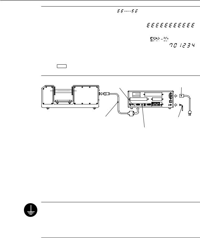
(3)Rear panel
|
Optional Interface add-on space |
|
(Second Analog I/O Unit, BCD Output Unit, GP-IB Unit) |
Name plate |
Optional Digimatic Output Unit |
|
add-on space |
|
AC power inlet |
|
SCAN SIG.-1 |
|
FOOT |
ID UNIT 1 |
|
SW. |
|
|
|
||
ID |
|
|
|
TRANSMITTER-1 |
REMOTE INTERLOCK |
RS-232C |
I/O ANALOG |
Fuse holder
AC power inlet
|
Foot switch |
ID Unit Protection cover |
Analog I/O connector |
Signal cable connector |
|
Scanning signal connector |
|
Remote interlock connector |
RS-232C connector |
TIP 1. A label which describes the terminal block name “I/O ANALOG” can be seen if the protective cover of the Analog I/O terminal block is opened. Use this for wiring.
2.The terminal located at the left end of the power input terminal and marked (by a
symbol  or
or  ) is the grounding terminal to keep the potential of signal line of this unit equal with other instrument connected. It is used to enhance resistance
against electrical interference.
IMPORTANT Precautions for wiring the terminal block
1.If wiring the I/O analog terminal and Power input terminal, do not directly touch the output terminals of the terminal block by hand, which has static charges, because the internal circuit may be damaged by static discharge.
If your hands are charged, discharge the static energy by touching the metallic surface of the Display Unit in advance. In addition, unplug the power cable from the outlet before commencing wiring.
2.After wiring has been completed, close the protective cover.
3.Do not touch the input terminals on the terminal block during operation, otherwise an operation error may result.
No. 99MBC071A |
1 - 3 |
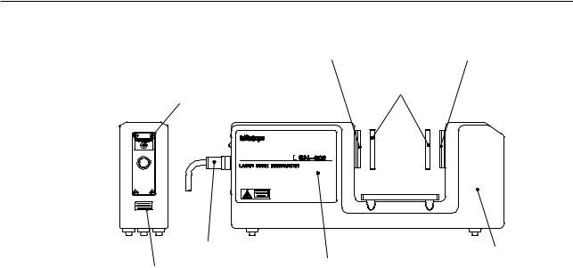
1.3.2Measuring Unit
Emission window |
Reception window |
Shutter
Laser emission indicator LED
Signal cable |
Reception unit |
Serial number label |
Emission unit |
|
1 - 4 |
No. 99MBC071A |

2 |
SETUP |
This chapter describes the connection between the Display Unit and |
|
Measuring Unit. |
2.1Unpacking and Acceptance Check
Your LSM has been thoroughly inspected prior to shipment. The mechanical, electrical, and optical systems are guaranteed to operate properly.
Unpack the package and check that the accessories, for the Display Unit or Measuring Unit, and signal cables, etc., are intact and not damaged.
Contact Mitutoyo if anything is damaged or missing.
2.2Connecting the Cables
Make sure that the power switch is turned off (turn the key switch counterclockwise to align with “O”, then pull it out), then connect the cables according to the following procedure.
Step 1: Integrating the option interface
For the option interface (Second Analog I/O Unit, BCD Output Unit, GP-IB Unit, and Digimatic Output Unit) to become available with the LSM, it must be installed by referring to Chapter 6.3 “Installing the Optional Interface Unit”.
For information about the setup switches on the BCD and GP-IB interface units refer to Section 6.2.3, “BCD Interface” and Section 6.2.4, “GP-IB Interface”, respectively.
No. 99MBC071A |
2 - 1 |
|
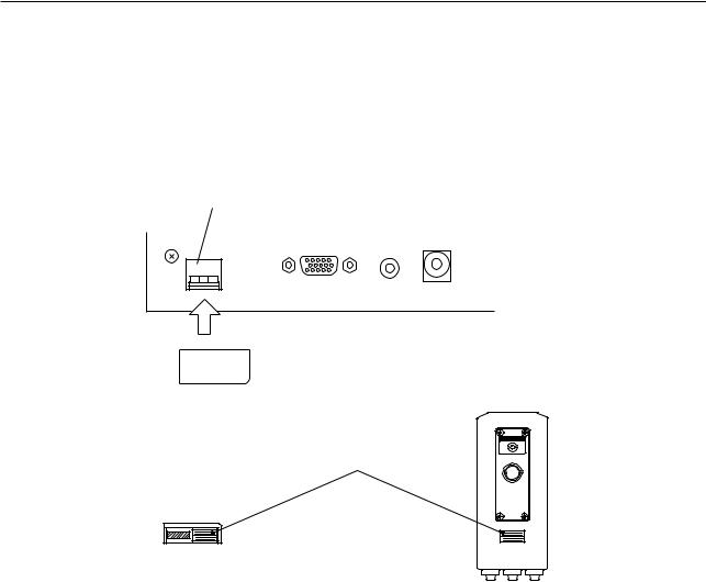
Step 2: Attaching the ID unit
1.Loosen the two screws that secure the ID unit protection cover at the left on the real panel of the Display Unit and remove the cover by sliding it rightward.
2.Remove the dummy ID unit (amber) that has been mounted at the left of the “TRANSMITTER-1” connector on the rear panel of the Display Unit, then insert the ID unit (beige) that comes in the same package as the Measuring Unit.
This ID unit stores critical data that ensures the accuracy of the Measuring Unit and has the same serial number as the accompanying Measuring Unit. Confirm that these two numbers are identical before inserting the ID unit.
ID unit slot |
|
ID UNIT 1 |
SCAN SIG.-1 |
TRANSMITTER-1 |
REMOTE INTERLOCK |
|
|
|
|
|
ID unit |
|
|
|
|
|
|
ID |
|
|
|
||
|
|
|
|||
Serial number label
ID unit
Measuring unit
3.Replace and secure the ID unit protection cover reversing the procedures in step 1 above.
2 - 2 |
No. 99MBC071A |
2. SETUP
IMPORTANT • |
If the dummy ID unit is still mounted, “ |
” |
|
|
PROG |
||||
|
is displayed in the lower section of the display. If |
|
||
|
|
|
||
|
this is the case, turn off the power and replace the |
|
||
|
dummy ID unit with a proper ID unit. |
|
|
|
• |
If the ID unit is not installed or if the serial number of |
|
||
|
||||
PROG |
||||
|
the Measuring Unit is not consistent with that on the |
|
||
|
ID unit, the system will not work and an error code |
|
|
|
|
as shown at the right will be displayed at power on. |
|
||
|
|
|||
|
At the same time, the 6-digit serial number of the |
|
|
|
|
measuring unit is displayed for confirmation. |
|
|
|
If the C key has been pressed to enter the ready state, measurement can be automatically started. However, the measuring accuracy can not be guaranteed.
ID unit Power cord
Signal cable |
GND lead wire |
Remote interlock
Step 3: Connecting the signal cable
Insert the round plug (12-pin) of the signal cable into the upper connector (12-pin) on the rear panel of the emission unit. Tighten the ring screw to firmly secure the connectors.
Insert the square connector (15-pin) on the other end of the signal cable into the connector “TRANSMITTER-1” at the upper left of the display rear panel and tighten the securing screws.
Step 4: Connecting the power cord and GND lead wire
Connect the supplied power cord to the AC connector at the upper right on the rear panel of the Display unit. Also be sure to ground the Display unit with the GND lead wire for improved resistance to noise.
Grounding must be done properly:
Connect the supplied grounding wire, after cutting it to the minimum length, to the grounding terminal provided on the Display Unit. This unit operates as a precision analog processor and, at the same time, a high-speed calculation unit. To enhance resistance against electrical interference and to increase safety, do not neglect grounding.
No. 99MBC071A |
2 - 3 |
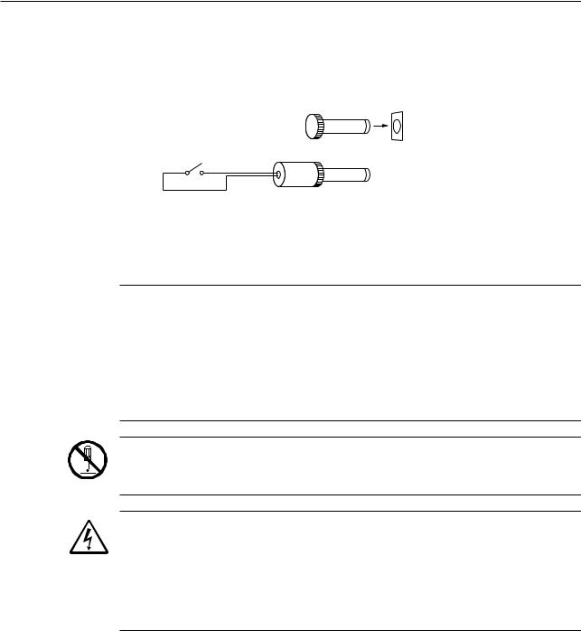
Step 5: Checking the remote interlock connector
Make sure that the short-circuiting pin is inserted into the “REMOTE INTERLOCK” connector on the rear panel of the Display Unit. If this short-circuiting pin is not inserted, laser emission is disabled, even if the power switch is on.
To emergency stop laser emission, refer to the following diagram.
Switch ON: Laser emission ON
Switch OFF: Laser emission OFF
|
Short-circuiting pin |
Switch |
|
5V, 3mA |
Applicable connector: PJ-2 |
|
(Manufacturer: Sato Parts) |
Step 6: Connecting the interface
For information about the procedure used to connect the interface, refer to Section 6.1.1, “I/O Analog Interface” and Section 6.1.2, “RS-232C Interface”.
IMPORTANT 1. Note the following when connecting the signal cable.
For information about the precautions to be observed when connecting the signal cable refer to the external view and dimensions in the Section 8.1, “LSM-6900 Display Unit”.
2.Note the following when making cable connections.
Always make connection or disconnection with the power cord unplugged. In addition, before connecting to the interface make sure that the power to all other units connected or to be connected are also off.
Do not disassemble this unit. This unit is a precision instrument. Should it be disassembled by the user, its accuracy can not be guaranteed even within the term of its warranty. And, there will be a charge for repairs.
Observe the following to avoid electric shock.
1.If an optional interface needs to be installed inside the Display Unit, unplug the power cord from the inlet and put the power switch in the OFF position, then pull off the key switch.
2.Do not remove the protective cover on which the seal is stuck to. Otherwise, an electric shock may result.
3.Do not remove the seal, shown at the left.
2 - 4 |
No. 99MBC071A |

2. SETUP
2.3Preliminary Checks
The necessary connections should be completed by following the procedure described in the previous chapter. Simplified operation checks are described here.
Step 1: Fully open the lens cap and shutter of the Measuring Unit.
Fully open the lens caps and beam shutters of both the emission unit and reception unit to ready the laser beam for emission.
The lens caps should be completely removed, and the shutters should be as shown in the diagram below.
Emission window

 Shutter window
Shutter |
|
If the shutter is closed |
If the shutter is open |
Step 2: Power on
•Turn the power key switch on the Display Unit clockwise until it is in the I (power on) position and the power is on.
•This unit enters the self check mode and all the LEDs and segments turn on. They will turn off shortly, and eights 


 will be displayed in the upper display section. When


 is displayed across the upper display section, the unit will turn off shortly. This is followed by the self check on the lower display section.
PROG |
|
|
|
PROG |
||
|
|
|
|
|
|
|
|
|
|
|
|
|
|
•In the lower display section eights 
 will appear sequentially from the left to right.
•After 


 is displayed across the lower display section, it will turn off shortly.
PROG |
|
PROG |
||||
|
|
|
|
|
|
|
|
|
|
|
|
|
|
•Measurement is started.
The LASER EMISSION LED turns on and the BUSY LED starts flashing to indicate the measurement has started from the ready state.
Since the objective segment has been set to |
PROG |
“SEG 1” at the factory, the displayed measure- |
|
ment shows the laser scanning range of the |
|
Measuring Unit. |
|
|
Here, the Display Unit is found to be normal because the scanning range is displayed. Proceed to Chapter 3, “DISPLAYS AND KEY OPERATIONS”, to custom set up each function.
No. 99MBC071A |
2 - 5 |
• An error may be displayed at this stage, |
PROG |
however, the display at the right is not actually |
|
an error. Check the shutter of the Measuring |
|
Unit. |
|
|
For information about other errors that may result refer to Section 7.3, “Error
Messages and Remedies”.
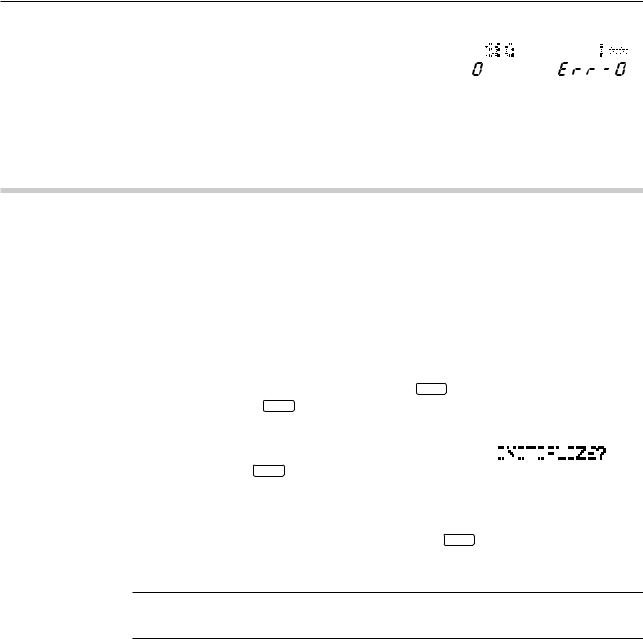
2.4Initializing the LSM-6900 Display Unit
After making sure that this unit is operating normally, initialize the Display Unit so it can recognize the Measuring Unit(s) to be used.
Initialization of the Display Unit is also required if the Measuring Unit needs to be changed.
In addition to replacing the ID unit that is associated with the Measuring Unit, initialize the Display Unit (i.e. restore the factory setups) with the following procedure.
The initialization procedure is as follows:
Step 1: Turn off the power and connect the Measuring Unit with the ID unit that comes with the Measuring Unit installed.
Step 2: Turn on the power while holding down the C |
key. |
||||||||||||||
Hold down the C |
key for approximately 2 seconds, even after the power is on. |
||||||||||||||
Step 3: When the self check has been completed, the |
|
|
|
|
|
|
|
|
|
|
|
|
|
|
|
|
PROG |
||||||||||||||
display shown at the right will appear. To initial- |
|
|
|
|
|
|
|
|
|
|
|
|
|
|
|
|
|
|
|
|
|
|
|
|
|
|
|
|
|
||
ize, press the ENT |
key. When the initialization |
|
|
|
|
|
|
|
|
|
|
|
|
|
|
process has been completed, the display restors |
|
|
|
|
|
|
|
|
|
|
|
|
|
|
|
|
|
|
|
|
|
|
|
|
|
|
|
|
|
||
the initial conditions that existed just after the |
|
|
|
|
|
|
|
|
|
|
|
|
|
|
|
power on. |
|
|
|
|
|
|
|
|
|
|
|
|
|
|
|
To abort initialization press a key other than the |
ENT key or turn the power off. |
||||||||||||||
In the former case the initialization process will be aborted and the initial display at power-on will be restored.
IMPORTANT Initialization will clear all the customer setup data and will restore the factory-setups. Customize the setups again as necessary.
2 - 6 |
No. 99MBC071A |
3 |
DISPLAYS AND KEY |
OPERATIONS |
This Display Unit is provided with many useful functions that can be customized according to the user's needs.
This chapter describes these functions and key operations.
3.1Outline of the Operation Modes
3.1.1Measurement Principle
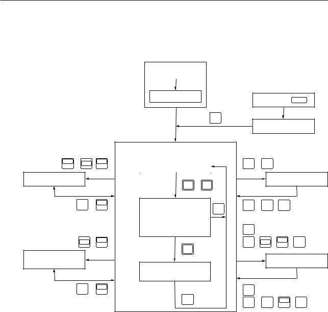
In order for the user to understand the measurement principle of the LSM, the following paragraphs describe about the system block diagram, segments (measurement positions) and measurement interval (measurement time).
3.1.1.1 Overview
Unlike light emitted from natural sources, a laser provides extremely fine, rectilinear beams which do not diffuse (coherent light beams).
Using the properties of the laser beam, the Mitutoyo Laser Scan Micrometer (LSM) moves a scanning laser beam over the workpiece and determines its dimensions by measuring the duration in which the beam is obstructed by the workpiece.
Emission unit |
|
|
|
Workpiece |
Reception unit |
Motor |
Colimator lens |
|
|
||
|
|
|
Condenser lens |
||
Polygon mirror |
|
|
|
||
|
|
|
Reception |
||
|
|
|
|
|
|
|
|
|
|
|
device S |
Polygon mirror |
|
|
|
|
|
|
|
|
Photoelectric element |
Amplifier |
|
Laser power source |
Semiconductor laser |
|
(reset signal generation) |
||
|
|
||||
MP |
|
RS |
|
|
|
Motor driving pulse |
Clock pulse |
t |
|
t |
t |
|
|
|
|||
|
ROM RAM |
Counter |
Gate |
Segment |
Edge signal |
|
|
||||
|
|
|
|
selection circuit |
|
Edge signal  RS
RS
CPU
Data display |
|
RS-232C |
|
I/O analog |
|
Foot switch |
|
Option I/F |
Keyboard |
|
|
interface |
|
|
|||
|
|
|
|
|
|
|
No. 99MBC071A |
3 - 1 |
|

The configuration of the system is shown in the above block diagram. A laser beam emitted from the laser oscillator is directed at the polygon mirror which rotates at high speed and is synchronized by clock pulses. The laser beam that is reflected by the polygon mirror is then collimated by the collimator lens towards the workpiece. As the polygon mirror rotates, this horizontal beam scans the workpiece and the beam not obstructed by the workpiece will reach the photoelectric element through the condenser lens and induce an output voltage in the photoelectric element. The output voltage will change according to the duration over which the laser beam is obstructed. Counting pulses generated during that period are used to determine the dimension of the obstructed portion. This data is sent to the CPU for processing and the dimensions are displayed digitally.
Consequently, either the dimensions of the workpiece (shadowed areas) or workpiece clearances (highlighted areas) can be determined by specifying the segments to be measured.
TIP In the system block diagram described in the previous page, the laser beam passed through the collimator lens is made parallel and, at the same time, stopped down so that the beam diameter is minimized at the measurement position.
3 - 2 |
No. 99MBC071A |
3. DISPLAYS AND KEY OPERATIONS
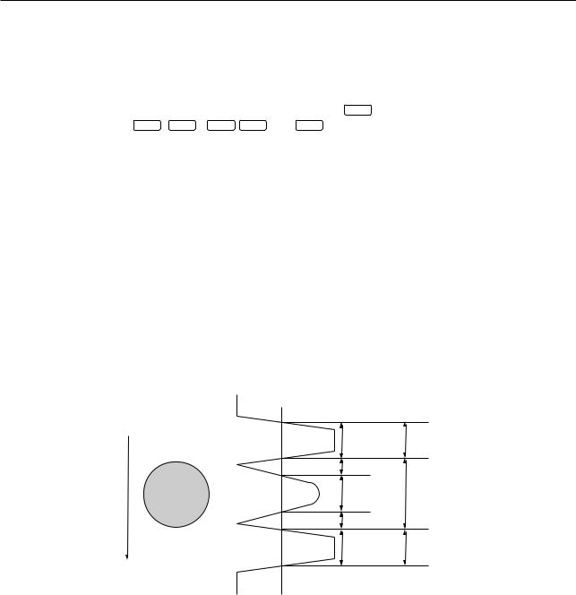
3.1.1.2 Setting the segment
Set the objective portion of a workpiece to be measured.
The highlighted and shaded portions created when the laser scans over the workpiece are controlled with each assigned number. In the basic setup a selection must be made from one of two cases: case where there are 1 to 4 highlighted and shaded sections, and case where there are 1 to 127 similar sections. In the former case the portions are controlled through the segment number, and are simply called segments. In the latter case the portions are controlled by the edge number (edge number is between 1 and 255) and called edges. Edge numbers equal to or greater than 256 are not available.
|
|
|
Segment specification |
|
|
|
|
|
|
|
SEG1 |
scanning |
|
|
Highlight 1 |
||
|
|||||
|
|
|
|
SEG2 |
|
|
|
Shade 1 |
|||
|
|
|
|||
|
|
|
|
|
SEG3 |
laser |
|
|
Highlight 2 |
||
|
|
|
|
SEG4 |
|
|
|
Shade 2 |
|||
of |
|
|
|||
|
|
|
|
|
|
|
|
|
|
|
|
Direction |
|
|
Highlight 3 |
SEG5 |
|
|
|
|
|||
|
|
|
|
|
SEG6 |
|
|
|
Shade 3 |
||
|
|
|
|
|
SEG7 |
|
|
|
Highlight 4 |
||
|
|
||||
|
|
|
|
|
|
•A maximum of 4 highlighted sections and a maximum of 3 shaded sections can be measured.
•Multiple segments can be specified at the same time.
•Specify segments 1 to 3 for a transparent object.
|
|
Edge specification |
|
|
|
|
EDGE1 |
|
|
|
|
|
|
Highlight 1 |
|
|
|
|
EDGE2 |
|
|
|
|
scanning |
|
Shade 1 |
|
|
Shade 2 |
||
|
|
|
EDGE3 |
|
|
Highlight 2 |
|
laserof |
|
|
EDGE4 |
|
|
||
|
|
EDGE5 |
|
Direction |
|
|
|
|
Highlight 127 |
||
|
|
||
|
|
|
EDGE254 |
|
|
|
|
|
|
Shade 127 |
|
|
|
|
EDGE255 |
|
|
|
|
|
|
Highlight 128 |
|
|
|
|
EDGE256 |
•A maximum of 127 highlighted sections and a maximum of 127 shaded sections can be measured.
•Always specify the start edge and finish edge numbers. These two edges can be either continued or separated. However, they must not be identical.
•Edge numbers can not be specified for a transparent object.
•If automatic measurement is specified in the basic setup, intervals, outside diameters, or gaps between the same shape of multiple pins can be
automatically measured.
No. 99MBC071A |
3 - 3 |

3.1.1.3 Measurement interval (measurement time)
A measurement interval (measurement time) varies depending on the averaging method and the number of scans selected for the measurement data.
There are two types of averaging method: the arithmetical average and the moving average. Select the one best suited for the user’s purpose.
1)Arithmetical average
•If a moving workpiece is measured, the diameter of the workpiece is determined by averaging the measured data taken from each section (a: first measurement, b: second measurement, .... n: nth measurement) of the workpiece the specified number of averaging times, as shown below.
first measurement
|
|
second measurement |
. . . |
nth measurement |
||||
|
|
|||||||
|
|
|
|
|||||
|
|
|
|
|||||
|
|
|
|
|
||||
|
|
|
|
|
|
|
|
|
a |
|
|
b |
|
|
n |
||
|
Moving workpiece |
|
|
|
Moving direction |
|||
|
|
|
|
|||||
•One of the following number of averaging times can be selected: 1, 2, 4, 8, ....1024, 2048.
•This is suitable for measuring a still object or the run-out of rollers, etc.
2)Moving average
In the moving average method, a measurement interval identical to that in the arithmetical average is divided into finer sections such as a1 (1st measurement), a2 (2nd measurement), - - - , an (nth measurement). Each measurement is performed almost in parallel. If, for example, the number of averaging times is set to 512, the first measurement requires the amount of time that corresponds to 512 scans. However, for the second measurement onward, only the time for 16 scannings is required. With respect to a workpiece with a changing diameter, this method provides data with smooth variation because of the many pieces of data, and also quickly detects the trend of workpiece diameter variation.
Measurement with |
Measurement with |
arithmetical averaging arithmetical averaging
an
. . . a2
a1
Moving workpiece
an measurement
. . .
a2 measurement
a1 measurement
 Moving direction Output of an measurement Output of a2 measurement Output of a1 measurement
•One of the following number of scans can be selected: 32, 64, 128, ....1024, 2048.
•This method is suitable for the feedback control of wire drawing machines and extruding machines.
3 - 4 |
No. 99MBC071A |
3. DISPLAYS AND KEY OPERATIONS
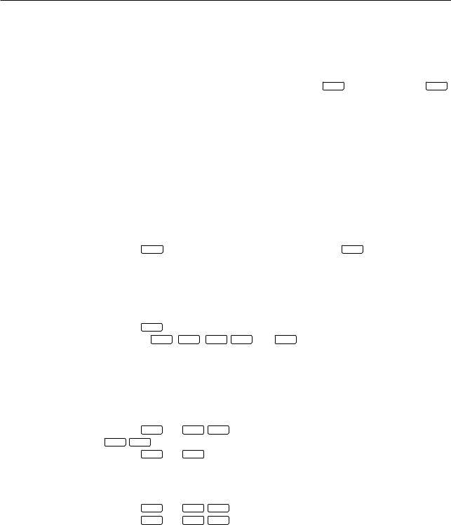
3.1.2Outline of the Operation Modes
The LSM system has the following modes:
1: Basic setup mode, 2: Calibration mode, 3: Function setup mode, 4: Other setup mode, 5: Statistical result display mode, and 6: Measurement mode.
Power ON |
Error check |
SET
Power ON + SET
1 : Basic setup mode
|
|
|
|
|
6 : Measurement mode |
|
|
LOCK |
, SHIFT |
|
LOCK |
|
Ready state |
H.CAL , |
L.CAL |
UNIT |
|
|
UNIT |
|
|
|
|
4: Other setup mode |
|
|
|
RUN , C.RUN |
|
2 : Calibration mode |
|
|
|
|
|
|
|
|
|
|
ENT |
( |
LOCK |
) |
Measurement in progress |
ENT |
( H.CAL , L.CAL ) |
|
UNIT |
||||||
|
|
|
|
|
|
|
|
|
|
|
|
|
(Program being executed) |
C |
|
|
|
|
|
|
|
|
|
•Single-run measurement
•Continuous-run
|
|
• measurement |
|
• |
SET |
|
|
|
|
|
SHIFT |
S.PR |
|
|
• |
LIMIT |
, SHIFT |
, |
MASTER |
, |
REF |
|
( RUN ) |
|
|
|
|
OFFSET |
|
|
||
|
|
|
|
|
|
|
|
|
||
5 : Statistical result |
|
|
|
|
|
3 : Function setup mode |
||||
display mode |
|
|
|
|
|
|||||
|
Measured data display |
|
|
|
|
|
|
|
||
|
|
|
|
|
|
|
|
|
||
|
|
(Latched display) |
|
|
|
|
|
|
|
|
SET |
S.PR |
|
|
|
|
|
|
|
|
|
( PRINT ) |
• Latch timer |
• |
SET |
|
|
|
|
|
||
|
|
|
|
|
|
|||||
|
|
• |
C |
• |
ENT |
( LIMIT |
, |
MASTER |
, |
REF ) |
|
|
|
||||||||
|
|
|
|
|
|
|
|
OFFSET |
|
|
No. 99MBC071A |
3 - 5 |
3.1.2.1Basic setup mode
•This mode is used to customize the basic setup conditions, including the resolution, interface conditions, and available functions, according to the measurement requirements. For more information, refer to Section 4.1, “Basic Setup”.
•To enter the basic setup mode turn on the power (turn the key switch clockwise from the “O” position to the “I” position) while holding down the SET key. Hold down the SET key for about 2 seconds to initiate the basic setup mode.
3.1.2.2Calibration mode
•Depending on the environment in which the LSM is used and the Display Unit - Measuring Unit combination, measurement errors may result. Therefore, always perform calibration prior to use, taking the measuring range and environmental conditions into account.
If calibration is performed, the errors described above will be reduced and high accuracy will be ensured.
•Before performing calibration, always make the setups for resolution, simultaneous measurement, and available segments in the basic setup mode. If this order is reverse, the previously set calibration values may be discarded.
•For more information, refer to Section 4.2, “Calibration”.
•Press the H.CAL key to enter the HI CAL mode; and press the L.CAL key to enter the LOW CAL mode.
3.1.2.3Measuring condition setup mode
•This mode is used to set up measuring conditions, including segments (objective portion of
|
workpiece to be measured) and GO/NG judgment criteria. |
• |
Press the SET key to enable all the function setup items established to be set in a batch. |
• |
Each of the LIMIT , SHIFT , MASTER / OFFSET , and REF keys allows the individual function |
|
setup item to be established. |
•Press the  key to enter the setup operation for the setup item which is used most often.
3.1.2.4Other setup mode
•This mode is used to set the key lock and to set the unit of measurement.
•Press the SHIFT and LOCK / UNIT key to turn on and off the key lock; and press only the
LOCK / UNIT key to enter the unit change mode.
•Press the SHIFT and READ key to enter the measuring position display mode.
3.1.2.5Statistic display mode
•Displays the statistical processing results.
• Press the SHIFT and STAT / S.E keys in the ready state to enter the statistic display mode.
•Press the SHIFT and S.PR / PRINT keys in the ready state to allow the statistical processing results to be printed.
3 - 6 |
No. 99MBC071A |

3. DISPLAYS AND KEY OPERATIONS
3.1.2.6 Measurement mode
This mode can be divided into the following operational states:
1)Measurement in the ready state
• This is the measurement mode that is entered immediately after the power is turned on
or if another measurement mode is aborted by pressing the C key (or by the RESET signal from the I/O interface or the “CL” command from the RS-232C/GP-IB interface).
•It is used to establish setups for calibration and available functions, which are not part of the basic setup items, or to enter another measurement mode including single-run measurement.
•Usually GO/NG judgment and analog output will not take place for measurement in the ready state, however, these specifications can be made in the basic setup mode.
•Measurements in the ready state are unavailable for statistical processing.
2)Single-run measurement
•If the RUN key (otherwise input RUN via the I/O interface or “R” command via the RS-232C/GP-IB interface) is pressed, one session of measurement is performed and the results will be automatically subject to GO/NG judgment and analog output. In addition, the measured data will be outputted for the RS-232C/GP-IB interface, Digimatic Output Unit, and printer. The measured data will be held (latched for the specified period) in the display.
•This data will be available for statistical processing.
3)Continuous-run measurement
•If the C.RUN key (otherwise input RUN+RESET via the I/O interface or “CR” command via the RS-232C/GP-IB interface) is pressed, one session of measurement is started and repeated the specified number of times. The measured data will be automatically subject to GO/NG judgment and analog output. In addition, the measured data will be outputted for the RS-232C/GP-IB interface, Digimatic Output Unit, and printer.
•Press the RUN or C.RUN key (or if RUN is received from the I/O interface) again to
terminate the measurement and hold the measured data on the display. If the C key
(or input RESET via the I/O interface or “CL” command via the RS-232C/GP-IB interface) is pressed halfway, the measurement is aborted and the ready state is returned to.
•The measurements are available for statistical processing.
4)Continuous measurement with a term specification
•This will take place where RUN input from the I/O interface has been assigned so as to start a term-specified continuous-run measurement in the basic setup.
•Repeatedly performs single-run measurement while RUN signal input continues, which is basically the same as the continuous-run measurement. Therefore, hereafter, continu- ous-run measurement includes the ones with a term specification.
•The measurements are available for statistical processing.
No. 99MBC071A |
3 - 7 |

5)Zero-run measurement
•A measurement where the number of samples is set to “0” is called a “zero-run measurement”.
•If the RUN key (otherwise input RUN via the I/O interface or the “R” command via the RS-232C/GP-IB interface) is pressed, single-run measurement is started and repeated until the RUN key is pressed again (or RUN is inputted via the I/O interface or the “STOP” command is inputted via the RS-232C/GP-IB interface). From the measured data the calculation items (mean, maximum value, minimum value, and range) that have been set for the sample measurement will be calculated and the resulting data will be automatically subject to GO/NG judgment and analog output. In addition, the measured data will be outputted for the RS-232C/GP-IB interface, Digimatic Output Unit, and printer. The measured data will be held on the display.
•The measured data are available for statistical processing.
•This is suitable for run-out measurement and cylindricity measurement.
6)Sample measurement
•A measurement where the number of samples is set to “2~999” is called a “sample measurement”.
•In practice this will take place as a single-run measurement or a continuous-run measurement (with a term specification).
From the measured data the calculation items (mean, maximum value, minimum value, and range) that have been set for the sample measurement will be calculated and the resulting data will be automatically subject to GO/NG judgment and analog output. In addition, the measured data will be outputted for the RS-232C/GP-IB interface, Digimatic Output Unit, and printer.
•The measured data are available for statistical processing.
•This is suitable for run-out measurement and cylindricity measurement.
7)Statistical processing
•Measured data from single-run and continuous-run measurements can be statistically processed (i.e. the number of measurement times, standard deviation, maximum value, minimum value, mean, and range are calculated).
These statistical processing results can be outputted for the display, printer (statistical memory for all programs will be cleared after printout), and RS-232C/GP-IB interface.
• Press the  S.E key (or input “ST” command via the RS-232C/GP-IB interface) to start statistical processing, and press it again (or input the “NST” command via the RS-232C/GP-IB interface) to terminate statistical processing.
•Press the A.CL / M.CL key to clear the statistical memory of the foreground program (case of a simultaneous measurement), and press the SHIFT and A.CL / M.CL keys to clear the statistical memory of all the programs.
•These statistical results data will be stored in memory while the power is on, and will be lost when the power is turned off.
3 - 8 |
No. 99MBC071A |
3. DISPLAYS AND KEY OPERATIONS
3.2Techniques and Terminology of Setup Functions
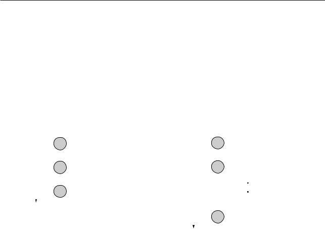
3.2.1Program
•A measurement will automatically be performed according to the registered (programmed) contents including the segment (feature to be measured) and GO/NG judgment criteria, etc., in advance. Registration is performed in the function setup mode.
•This unit can hold a maximum of 10 programs, which may include various settings suitable for up to ten kinds of workpieces.
•The user can select, in the basic setup, whether these ten programs are used as individual programs (referred to as “single measurement”) or as five pairs of programs (referred to as “simultaneous measurement”).
a)Single measurement
One session of measurement is performed according to the one specified program. This is the factory default.
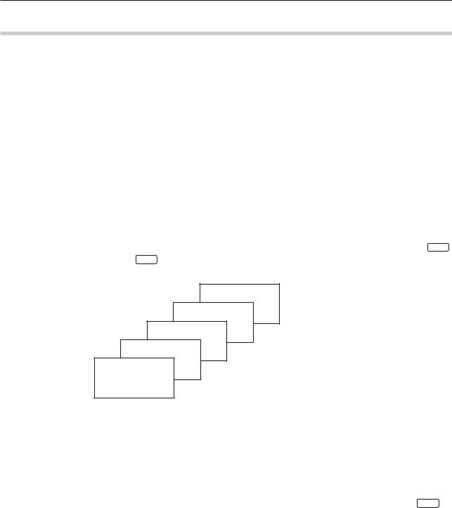
b)Simultaneous measurement
• In one measurement session two programs are executed at one time as a pair. These
pairs are formed as shown in the figure below.
• To run a pair of programs, either of the two can be specified via numeric keys 0 to 9 and the one specified is called “foreground” program, and its counterpart is called “background” program.
Pair 4: Program No.4
Pair 3: Program PrNo.gram3 No.9
Pair 2: Program PrNo.gram2 No.8
Pair 1: Program PrNo.gram1 No.7
Pair 0: Program PrNo.gram0 No.6
Program No.5
3.2.2Basic setup
•This is used to customize the basic setup conditions, including the resolution, available functions, and interface conditions, according to the measurement requirements.
•This basic setup must be performed at the beginning of a measurement. Note that changing the setup of resolution or simultaneous measurement in this basic setup cancel the existing calibration values and function setup.
•The basic setup mode is entered by turning on the power while holding down the SET key.
Note that no response will be made to an I/O interface input and RS-232C/GP-IB command in the basic setup mode.
•For more information, refer to Section 4.1, “Basic Setup”.
No. 99MBC071A |
3 - 9 |
3.2.3Function setup
•Use this procedure to set up the conditions necessary for measurement.
For each program number register measurement conditions including the segment (part feature to be measured), measurement interval (measurement time), and GO/NG judgment criteria that are the best suited for the objective workpiece.
•To enter the function setup mode press the SET key in the ready state. Each of the
LIMIT , SHIFT + MASTER / OFFSET , and REF keys allows the individual setup item to be established, and the  key enters the setup operation for items which are most frequently accessed for set up.
•For more information refer to Section 4.5, “Setting Up the Functions”.
3.2.4Setups according to the property of each workpiece
For measuring workpieces that transmit light or have a dimension smaller than the diameter of the scanning beam it is critical to make setups that take into account the properties of the workpiece.
3.2.4.1Transparent object (Workpiece that transmits light)
a)Round bar
•Workpieces such as fiber optics and glass tubes are more or less transparent, while workpieces made of steel are not. This requires different segment settings.
The segment settings for an opaque object and a transparent object are as follows:
•Setup for measurement of transparent or opaque object is possible in the basic setup.
|
|
Photo-electric signal |
|
|
|
|
|
Laser scan direction |
|
|
|
Transparetnt |
Segment 1 |
Segment 1 |
|
Workpiece |
|
|
|
|
|
Segment 2 |
|
|
|
Segment 3 |
Segment 2 |
|
|
Segment 4 |
|
|
|
Segment 5 |
Segment 3 |
|
|
For opaque mode |
For transparent mode |
|
|
||
Binary voltage (SHL)
b)Plate (Sheet)
•If the workpiece being measured is a transparent plate (sheet) with edges that are not chamfered or beveled, measurement may be aborted because there is not a sharp contrast in the amount of light at the transition from the highlighted portion to the shaded portion.
3.2.5Latch (holding) of the displayed value
•In a single-run measurement, etc., GO/NG judgment and analog output will be continued while the measured data is latched (held) on the display for the specified period of time. After the set period elapses, system operation returns to the ready state.
•Set up the display latch timer in the basic setup.
•While the display is being latched, inputs from the I/O interface or RS-232C/GP-IB are still valid.
3 - 10 |
No. 99MBC071A |
 Loading...