


SPLIT-TYPE, HEAT PUMP AIR CONDITIONERS
No.OC304
REVISED EDITION-A
TECHNICAL & SERVICE MANUAL
R410A
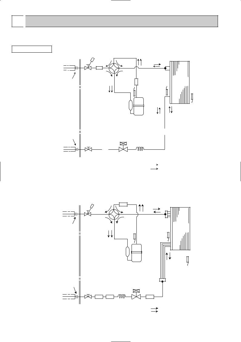
Outdoor unit |
|
[model names] |
[Service Ref.] |
SUZ-A09VR |
SUZ-A09VR.TH |
SUZ-A12VR |
SUZ-A12VR.TH |
SUZ-A18VR |
SUZ-A18VR.TH |
SUZ-A24VR |
SUZ-A24VR.TH |
HFC
utilized
R410A
|
CONTENTS |
|
|
1. COMBINATION OF INDOOR AND OUTDOOR UNITS ····· |
|
|
2. TECHNICAL CHANGES ·············· |
|
|
3. PART NAMES AND FUNCTIONS·········· |
|
Indication of |
4. SPECIFICATION················· |
|
model name |
5. NOISE CRITERIA CURVES ············ |
|
|
||
|
6. OUTLINES AND DIMENSIONS ··········· |
|
|
7. WIRING DIAGRAM ················ |
|
|
8. REFRIGERANT SYSTEM DIAGRAM ········ |
|
|
9. PERFORMANCE CURVES ············· |
|
SUZ-A09VR.TH SUZ-A12VR.TH |
10. ACTUATOR CONTROL·············· |
|
11. SERVICE FUNCTIONS··············· |
||
|
||
Revision : |
12. TROUBLESHOOTING··············· |
|
• SUZ-A18VR.TH and SUZ-A24VR.TH are added in |
13. DISASSEMBLY INSTRUCTIONS·········· |
|
REVISED EDITION-A. |
14. PARTS LIST··················· |
|
|
NOTE:
This service manual describes technical data of the outdoor units.
•As for indoor units SLZ-A09AR.TH, SLZ-A12AR.TH, SLZ-A18AR.TH, SEZ-A12AR.TH, SEZ-A18AR.TH, SEZ-A24AR.TH and SEZ-A09CR.W, refer to the service manual OC302 and OC303.
• Please void OC304.
1 
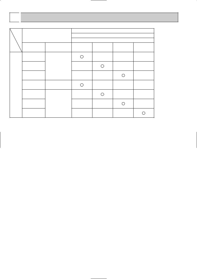
 COMBINATION OF INDOOR AND OUTDOOR UNITS
|
|
|
|
|
Outdoor unit |
|
|
|
|
Indoor unit |
|
Heat pump type |
|
||
|
|
|
|
|
SUZ- |
|
|
|
|
Service Ref. |
Service |
A09VR.TH |
A12VR.TH |
A18VR.TH |
A24VR.TH |
|
|
Manual No. |
|||||
|
|
|
|
|
|
|
|
|
|
SLZ-A09AR.TH |
|
|
— |
— |
— |
|
|
SLZ-A12AR.TH |
OC302 |
— |
|
— |
— |
|
without electric heater |
SLZ-A18AR.TH |
|
— |
— |
|
— |
Heat pump |
SEZ-A09CR.W |
— |
|
— |
— |
— |
|
SEZ-A12AR.TH |
|
— |
|
— |
— |
||
|
|
SEZ-A18AR.TH |
OC303 |
— |
— |
|
— |
|
|
SEZ-A24AR.TH |
|
— |
— |
— |
|
2
2 
 TECHNICAL CHANGES
INFORMATION FOR THE AIR CONDITIONER WITH R410A REFRIGERANT
•This room air conditioner adopts an HFC refrigerant (R410A) which never destroys the ozone layer.
•Pay particular attention to the following points, though the basic installation procedure is same as that for R22 conditioners. 1 As R410A has working pressure approximate 1.6 times as high as that of R22, some special tools and piping parts/
materials are required. Refer to the table below.
2 Take sufficient care not to allow water and other contaminations to enter the R410A refrigerant during storage and installation, since it is more susceptible to contaminations than R22.
3 For refrigerant piping, use clean, pressure-proof parts/materials specifically designed for R410A. (Refer to 2. Refrigerant piping.)
4 Composition change may occur in R410A since it is a mixed refrigerant. When charging, charge liquid refrigerant to prevent composition change.
Refrigerant
Refrigerating |
oil |
|
New refrigerant |
Previous refrigerant |
Refrigerant |
R410A |
R22 |
|
|
|
Composition (Ratio) |
HFC-32: HFC-125 (50%:50%) |
R22 (100%) |
|
|
|
Refrigerant handling |
Pseudo-azeotropic refrigerant |
Single refrigerant |
|
|
|
Chlorine |
Not included |
Included |
|
|
|
Safety group (ASHRAE) |
A1/A1 |
A1 |
|
|
|
Molecular weight |
72.6 |
86.5 |
|
|
|
Boiling point (:) |
-51.4 |
-40.8 |
Steam pressure [25:](Mpa) |
1.557 |
0.94 |
Saturated steam density [25:](Kg/K) |
64 |
44.4 |
Combustibility |
Non combustible |
Non combustible |
|
|
|
ODP w1 |
0 |
0.055 |
|
|
|
GWP w2 |
1730 |
1700 |
|
|
|
Refrigerant charge method |
From liquid phase in cylinder |
Gas phase |
|
|
|
Additional charge on leakage |
Possible |
Possible |
Kind |
Incompatible oil |
Compatible oil |
|
|
|
Color |
Non |
Light yellow |
|
|
|
Smell |
Non |
Non |
|
|
|
w1 :Ozone Destruction Parameter |
: based on CFC-11 |
w2 :Global Warmth Parameter |
: based on CO2 |
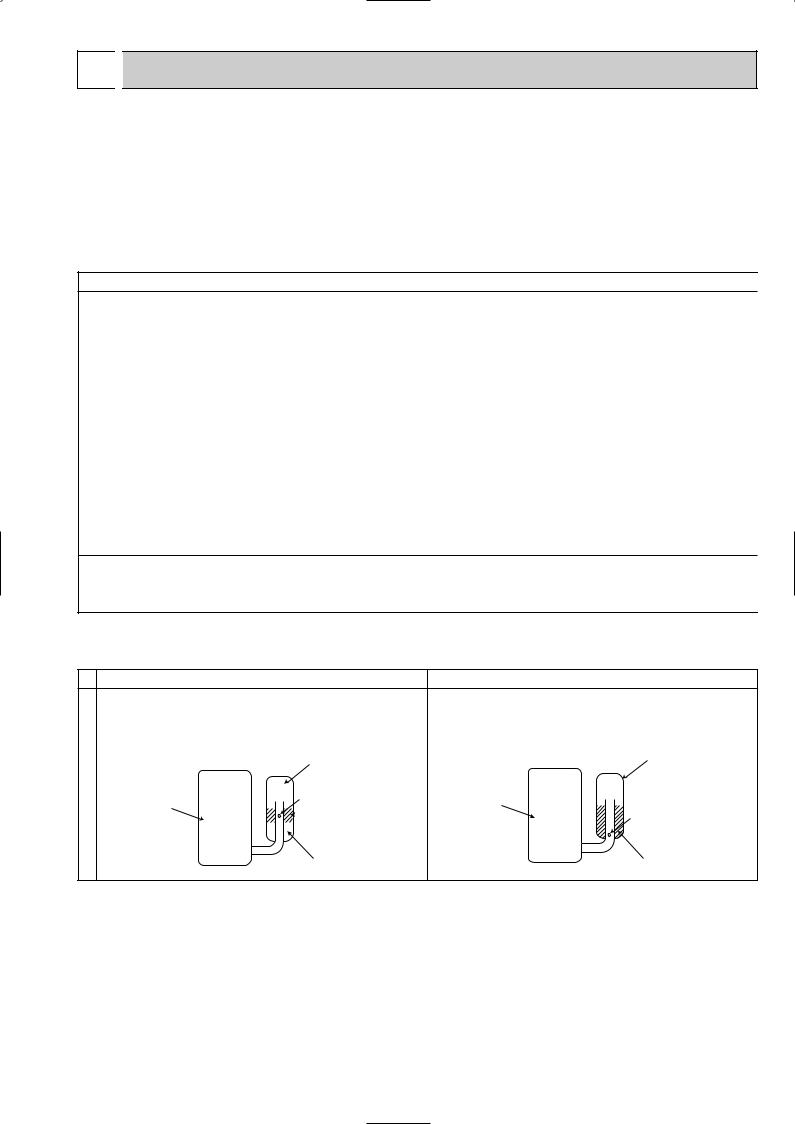
Compressor
|
New Specification |
Current Specification |
|||||||||||||
The incompatible refrigerating oil easily separates from |
Since refrigerant and refrigerating oil are compatible each, |
||||||||||||||
refrigerant and is in the upper layer inside the suction muffler. |
refrigerating oil backs to the compressor through the lower |
||||||||||||||
Raising position of the oil back hole enables to back the |
position oil back hole. |
||||||||||||||
refrigerating oil of the upper layer to flow back to the |
|
|
|
|
|
|
|
||||||||
compressor. |
|
|
|
|
|
|
Suction muffler |
|
|
|
|
|
|
Suction muffler |
|
|
|
|
|
|
|
|
|
|
|
|
|||||
|
|
|
|
|
|
|
Oil back hole |
|
|
|
|
|
|
|
|
Compressor |
|
|
|
|
|
|
Compressor |
|
|
||||||
|
|
|
|
|
|
|
|
Refrigerating oil |
|
|
|
|
|
|
Oil back hole |
|
|
|
|
|
|
|
|
|
|
|
|
|
|
||
|
|
|
|
|
|
|
|
||||||||
Refrigerating oil /Refrigerant
NOTE : The unit of pressure has been changed to MPa on the international system of units(SI unit system). The conversion factor is: 1(MPa [Gauge]) =10.2(kgf/f [Gauge])
3
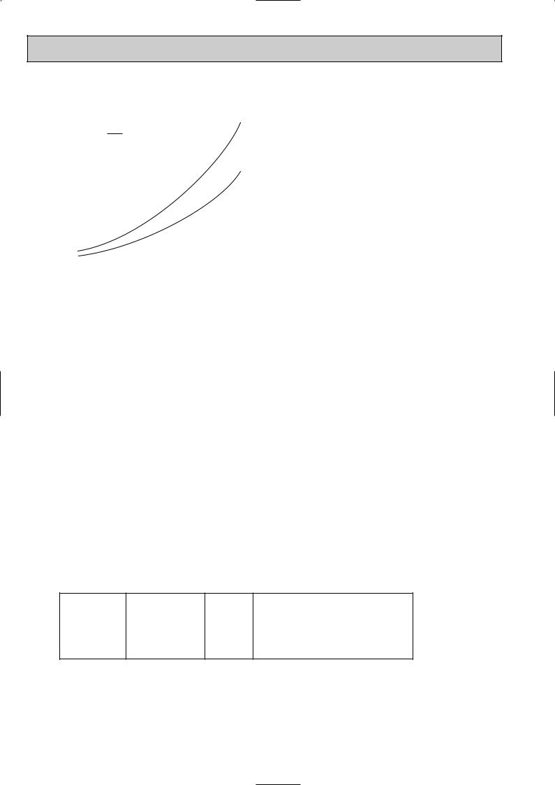
Conversion chart of refrigerant temperature and pressure
(MPa [Gauge]) |
|
|
|
|
|
|
|
|
|
|
|
|
|||
|
4.0 |
|
|
|
|
|
|
|
|
|
|
|
|
|
|
|
3.5 |
|
|
|
|
|
|
|
|
|
|
|
|
|
|
pressure |
|
|
|
|
|
R410A |
|
|
|
|
|
|
|||
|
|
|
|
|
|
|
|
|
|
|
|||||
|
|
|
|
|
|
|
|
|
|
|
|
||||
3.0 |
|
|
|
|
|
R22 |
|
|
|
|
|
|
|||
|
|
|
|
|
|
|
|
|
|
|
|
||||
liquid |
2.5 |
|
|
|
|
|
|
|
|
|
|
|
|
|
|
|
|
|
|
|
|
|
|
|
|
|
|
|
|
||
|
|
|
|
|
|
|
|
|
|
|
|
|
|
||
2.0 |
|
|
|
|
|
|
|
|
|
|
|
|
|
NOTE : The unit of pressure has been changed to MPa on the |
|
|
|
|
|
|
|
|
|
|
|
|
|
|
|||
1.5 |
|
|
|
|
|
|
|
|
|
|
|
|
|
||
Saturated |
|
|
|
|
|
|
|
|
|
|
|
|
|
||
1.0 |
|
|
|
|
|
|
|
|
|
|
|
|
|
international system of units(SI unit system). |
|
|
|
|
|
|
|
|
|
|
|
|
|
|
|
||
|
|
|
|
|
|
|
|
|
|
|
|
|
|
The conversion factor is: 1(MPa [Gauge]) =10.2(kgf/f [Gauge]) |
|
|
|
|
|
|
|
|
|
|
|
|
|
|
|
||
|
0.5 |
|
|
|
|
|
|
|
|
|
|
|
|
|
|
|
|
|
|
|
|
|
|
|
|
|
|
|
|
|
|
|
|
|
|
|
|
|
|
|
|
|
|
|
|
|
|
|
0.0 |
|
|
|
|
|
|
|
|
|
|
|
|
|
|
|
|
|
|
|
|
|
|
|
|
|
|
|
|
|
|
|
-0.5 |
|
|
|
|
|
|
|
|
|
|
|
|
|
|
|
-30 -20 |
-10 0 10 20 30 40 50 60 (:) |
|||||||||||||
1. Tools dedicated for the air conditioner with R410A refrigerant
The following tools are required for R410A refrigerant. Some R22 tools can be substituted for R410A tools.
The diameter of the service port on the stop valve in outdoor unit has been changed to prevent any other refrigerant being charged into the unit. Cap size has been changed from 7/16 UNF with 20 threads to 1/2 UNF with 20 threads.
R410A tools |
Can R22 tools be used? |
Description |
|
|
|
R410A has high pressures beyond the measurement range of existing |
|
Gauge manifold |
No |
gauges. Port diameters have been changed to prevent any other refrigerant |
|
|
|
from being charged into the unit. |
|
|
|
|
|
Charge hose |
No |
Hose material and cap size have been changed to improve the pressure |
|
resistance. |
|||
|
|
||
Gas leak detector |
No |
Dedicated for HFC refrigerant. |
|
|
|
|
|
Torque wrench |
Yes |
6.35 mm and 9.52 mm |
|
No |
12.7 mm |
||
|
|||
|
|
|
|
Flare tool |
Yes |
Clamp bar hole has been enlarged to reinforce the spring strength in the tool. |
|
|
|
|
|
Flare gauge |
New |
Provided for flaring work (to be used with R22 flare tool). |
|
Vacuum pump |
New |
Provided to prevent the back flow of oil. This adapter enables you to use |
|
adapter |
vacuum pumps. |
||
|
|||
Electronic scale for |
New |
It is difficult to measure R410A with a charging cylinder because the |
|
refrigerant charging |
refrigerant bubbles due to high pressure and high-speed vaporization |
||
|
|||
|
|
|
No : Not Substitutable for R410A Yes : Substitutable for R410A
2. Refrigerant piping
1Specifications
Use the refrigerant pipes that meet the following specifications.
Pipe |
Outside diameter |
Wall |
Insulation material |
|
mm |
thickness |
|||
|
|
|||
|
|
|
|
|
For liquid |
6.35 |
0.8 mm |
Heat resisting foam plastic |
|
For gas |
9.52 |
0.8 mm |
||
Specific gravity 0.045 Thickness 8 mm |
||||
|
|
|||
|
|
12.70.8 mm
•Use a copper pipe or a copper-alloy seamless pipe with a thickness of 0.8 mm. Never use any pipe with a thickness less than 0.8mm, as the pressure resistance is insufficient.
4
2Flaring work and flare nut
Flaring work for R410A pipe differs from that for R22 pipe.
For details of flaring work, refer to Installation manual “FLARING WORK”.
Pipe diameter |
Dimension of flare nut |
|
|
|
|
|
|
mm |
R410A |
|
R22 |
6.35 |
17 |
|
17 |
9.52 |
22 |
|
22 |
12.7 |
26 |
|
24 |
3. Refrigerant oil
Apply the special refrigeration oil (accessories: packed with indoor unit) to the flare and the union seat surfaces.
4.Air purge
•Do not discharge the refrigerant into the atmosphere.
Take care not to discharge refrigerant into the atmosphere during installation, reinstallation, or repairs to the refrigerant circuit.
•Use the vacuum pump for air purging for the purpose of environmental protection.
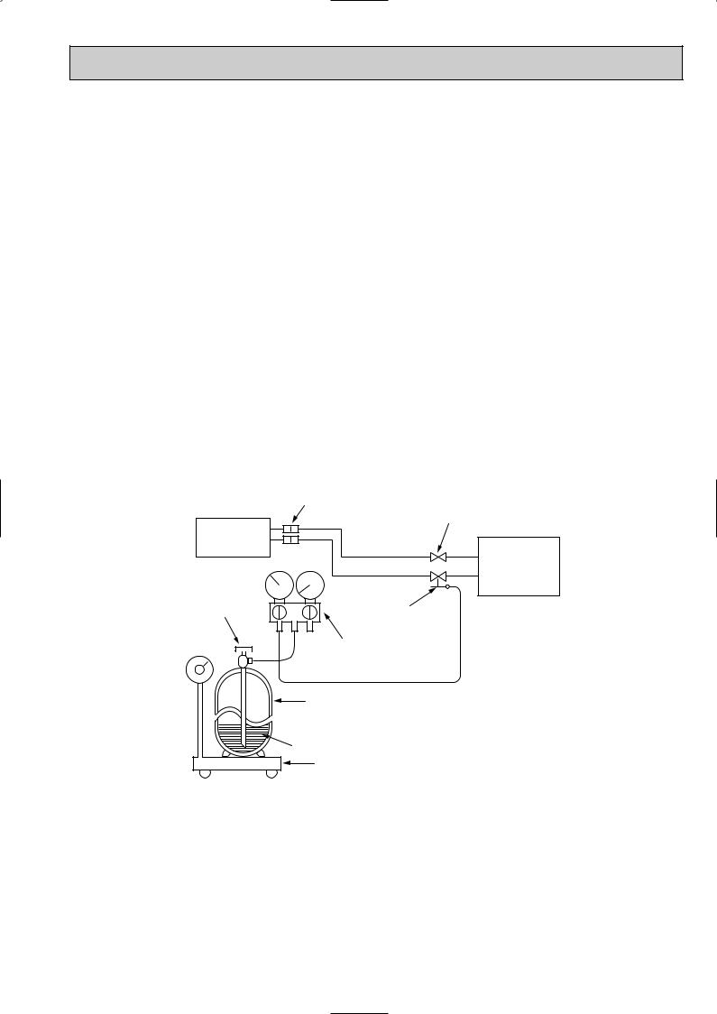
5.Additional charge
For additional charging, charge the refrigerant from liquid phase of the gas cylinder.
If the refrigerant is charged from the gas phase, composition change may occur in the refrigerant inside the cylinder and the outdoor unit. In this case, ability of the refrigerating cycle decreases or normal operation can be impossible. However, charging the liquid refrigerant all at once may cause the compressor to be locked. Thus, charge the refrigerant slowly.
Indoor unit
Refrigerant gas cylinder operating valve
Union
|
Stop valve |
Liquid pipe |
|
Gas pipe |
Outdoor unit |
Service port
Gauge manifold valve (for R410A)
 Charge hose (for R410A)
Refrigerant gas cylinder for R410A with siphon
Refrigerant (liquid)
Electronic scale for refrigerant charging
5

3 
 PART NAMES AND FUNCTIONS
SUZ-A09VR.TH |
ACCESSORIES |
|
SUZ-A12VR.TH |
||
|
||
OUTDOOR UNIT |
|
Air inlet |
|
|
|
(back and side) |
|
SUZ-A09VR.TH |
|
Piping |
|
||
Drain hose |
|
SUZ-A12VR.TH |
|
1 Drain socket |
1 |
||
|
Air outlet
Drain outlet
SUZ-A18VR.TH |
ACCESSORIES |
|
SUZ-A24VR.TH |
||
|
||
OUTDOOR UNIT |
|
Air inlet
(back and side) |
SUZ-A18VR.TH |
|
|
Piping |
SUZ-A24VR.TH |
1 Drain socket |
1 |
Drain hose |
|
2 Drain cap [33 |
2 |
Air outlet |
|
Drain outlet |
|
6
4 |
|
SPECIFICATION |
|
|
|
|
|
||||
|
|
|
|
|
|
|
|
|
|
||
SLZ-A•AR.TH / SUZ-A•VR.TH |
|
|
|
|
|
|
|
||||
|
|
|
|
|
|
|
|
|
|||
|
|
|
|
|
|
SUZ-A09VR.TH |
SUZ-A12VR.TH |
SUZ-A18VR.TH |
|||
|
|
|
Outdoor Service Ref. |
|
Indoor Service Ref. |
Indoor Service Ref. |
Indoor Service Ref. |
||||
|
|
|
|
|
|
SLZ-A09AR.TH |
SLZ-A12AR.TH |
SLZ-A18AR.TH |
|||
|
|
|
|
|
|
|
|
|
|
|
|
|
|
|
Function |
|
Cooling |
Heating |
Cooling |
Heating |
Cooling |
Heating |
|
|
|
|
Power supply |
|
Single phase |
Single phase |
Single phase |
||||
|
|
|
|
230V,50Hz |
230V,50Hz |
230V,50Hz |
|||||
|
|
|
|
|
|
||||||
Capacity |
Air flow(High/Loww) |
K /h |
1900 |
1900 |
2,940/1,320w |
2,940/2,210w |
|||||
|
|
Capacity Rated frequency(Min.~Max.) |
kW |
2.5(0.9-3.2) |
3.0(0.9-4.3) |
3.2(1.0-3.6) |
3.8(0.9-4.8) |
4.6(1.1-5.2) |
5.0(0.9-6.5) |
||
|
|
Dehumidification |
|
r/h |
1.4 |
— |
1.8 |
— |
2.3 |
— |
|
|
|
|
|
|
|
|
|
|
|
|
|
Electrical |
data |
Fan motor current |
A |
0.24 |
0.24 |
0.30 |
|||||
|
|
Starting current |
1 |
A |
4.20 |
4.90 |
7.40 |
||||
|
|
Compressor motor current 1 |
A |
3.28 |
3.78 |
4.43 |
4.43 |
6.86 |
6.46 |
||
|
|
|
|
|
|
|
|
||||
Coefficient of performance (C.O.P) |
3.29 |
3.45 |
3.02 |
3.55 |
2.82 |
3.23 |
|||||
Compressor |
resistance(at 20:) |
|
V-W 1.53 |
V-W 0.49 |
V-W 0.45 |
||||||
|
|
Model |
|
|
KNB073FBVH |
KNB092FAAH |
SNB130FLDH |
||||
|
|
Output |
|
W |
550 |
650 |
850 |
||||
|
|
Winding |
|
" |
U-V 1.53 |
U-W 1.53 |
U-V 0.49 |
U-W 0.49 |
U-V 0.45 |
U-W 0.45 |
|
|
|
|
|
|
|
|
|
|
|
|
|
|
|
|
|
|
|
|
|
||||
|
motor |
Model |
|
|
RA6V21-AA |
RA6V21-AA |
PM8H60-UB |
||||
Fan |
Winding |
|
" |
WHT-BLK 347 |
WHT-BLK 347 |
BLK-WHT 15.2 |
|||||
|
|
|
|
||||||||
|
|
resistance(at 20:) |
|
BLK-RED 281 |
BLK-RED 281 |
WHT-RED 15.2 |
RED-BLK 15.2 |
||||
|
|
Dimensions WOHOD |
mm |
800o550o285 |
800o550o285 |
840o850o330 |
|||||
|
|
Weight |
|
kg |
|
33 |
|
34 |
53 |
||
|
|
Sound level |
|
dB |
|
46 |
47 |
48 |
53/50w |
55/53w |
|
|
|
Fan speed |
|
rpm |
825 |
825 |
800/400w |
800/620w |
|||
|
|
Fan speed regulator |
|
|
1 |
|
1 |
2 |
|||
|
|
Refrigerant filling |
|
kg |
0.80 |
0.90 |
1.80 |
||||
|
|
capacity(R410A) |
|
||||||||
|
|
|
|
|
|
|
|
|
|
||
Special |
remarks |
Refrigerating oil (Model) |
cc |
320 (NEO22) |
320 (NEO22) |
450 (NEO22) |
|||||
Thermistor RT61 (at 0:) |
k" |
32.6 |
32.6 |
— |
|
||||||
|
|
|
|||||||||
|
|
Thermistor RT62 (at 100:) |
k" |
13.4 |
13.4 |
— |
|
||||
|
|
Thermistor RT64 (at 50:) |
k" |
|
17 |
|
17 |
— |
|
||
|
|
Thermistor RT65 (at 25:) |
k" |
|
10 |
|
10 |
— |
|
||
|
|
Thermistor RT61 (at 100:) |
k" |
|
— |
|
— |
13.4 |
|||
|
|
Thermistor RT62 (at 25:) |
k" |
|
— |
|
— |
10.0 |
|||
|
|
Thermistor RT65 (at 50:) |
k" |
|
— |
|
— |
17.0 |
|||
|
|
Thermistor RT68 (at 25:) |
k" |
|
— |
|
— |
10.0 |
|||
NOTE : Test conditions are based on ISO 5151 |
|
|
|
|
|
||||||
|
|
Cooling : Indoor |
D.B. 27: W.B. 19: |
|
|
|
|
|
|||
|
|
|
Outdoor D.B. 35: W.B. 24: |
|
|
|
|
|
|||
|
|
Heating : Indoor |
D.B. 20: W.B. 15: |
|
|
|
|
|
|||
|
|
|
Outdoor D.B. 7: W.B. 6: |
|
|
|
|
|
|||
Refrigerant piping length (one way): 5m
1 Measured under rated operating frequency.
7
SEZ-A•CR.W / SUZ-A•VR.TH
|
|
Outdoor Service Ref. |
|
|
|
|
|
Function |
|
|
|
Capacity |
Power supply |
|
|
||
Air flow |
|
K /h |
|
||
|
|
Capacity Rated frequency(Min.~Max.) |
kW |
|
|
Electrical |
|
Dehumidification |
|
r/h |
|
data |
Fan motor current |
A |
|
||
|
|
Starting current |
1 |
A |
|
|
|
Compressor motor current 1 |
A |
|
|
Coefficient of performance(C.O.P) |
|
||||
Compressor |
resistance(at 20:) |
|
|
||
|
|
Model |
|
|
|
|
|
Output |
|
W |
|
|
|
Winding |
|
" |
|
|
|
|
|
|
|
Fan |
motor |
Model |
|
" |
|
Winding |
|
|
|||
|
|
|
|
|
|
|
|
resistance(at 20:) |
|
|
|
|
|
Dimensions WOHOD |
mm |
|
|
|
|
Weight |
|
kg |
|
|
|
Sound level |
|
dB |
|
|
|
Fan speed |
|
rpm |
|
|
|
Fan speed regulator |
|
|
|
Special |
remarks |
Refrigerant filling |
|
kg |
|
capacity(R410A) |
|
|
|||
|
|
|
|
||
|
|
|
|
|
|
|
|
Refrigerating oil (Model) |
cc |
|
|
|
|
Thermistor RT61(at 0:) |
k" |
|
|
|
|
Thermistor RT62(at 100:) |
k" |
|
|
|
|
Thermistor RT64(at 50:) |
k" |
|
|
|
|
Thermistor RT65(at 25:) |
k" |
|
|
NOTE : Test conditions are based on ISO 5151 |
|||||
|
|
Cooling : Indoor |
D.B. 27: W.B. 19: |
||
|
|
Outdoor D.B. 35: W.B. 24: |
|||
|
|
Heating : Indoor |
D.B. 20: W.B. 15: |
||
|
|
Outdoor D.B. 7: W.B. 6: |
|||
Refrigerant piping length (one way): 5m
1 Measured under rated operating frequency.
SUZ-A09VR.TH
Indoor Service Ref. SEZ-A09CR.W
Cooling Heating
Single phase |
|
230V,50Hz |
|
2.4 (1.0-3.2) |
3.0 (0.9-4.2) |
1.4 |
— |
|
1900 |
|
4.30 |
3.08 |
3.78 |
|
0.24 |
3.24 |
3.41 |
KNB073FBVH |
|
|
550 |
U-V 1.53 |
U-W 1.53 |
V-W 1.53
RA6V21-AA
WHT-BLK 347
BLK-RED 281
800o550o285
33
46
825
1
0.80
320 (NEO22)
32.6
13.4
17
10
8
SEZ-A•AR.TH / SUZ-A•VR.TH
Outdoor Service Ref.
Function
Power supply
Capacity |
Air flow(High/Loww) |
K /h |
||
|
|
Capacity Rated frequency(Min.~Max.) |
kW |
|
Electrical |
|
Dehumidification |
r/h |
|
data |
Fan motor current |
A |
||
|
|
Starting current 1 |
A |
|
|
|
Compressor motor current 1 |
A |
|
Coefficient of performance(C.O.P) |
||||
Compressor |
resistance(at 20:) |
|
||
|
|
Model |
|
|
|
|
Output |
W |
|
|
|
Winding |
" |
|
|
|
|
||
Fan |
motor |
Model |
" |
|
Winding |
||||
|
|
|
||
|
|
resistance(at 20:) |
|
|
|
|
Dimensions WOHOD |
mm |
|
|
|
Weight |
kg |
|
|
|
Sound level(High/Loww) |
dB |
|
|
|
Fan speed(High/Loww) |
rpm |
|
|
|
Fan speed regulator |
|
|
|
|
Refrigerant filling |
kg |
|
|
|
capacity(R410A) |
||
|
|
|
||
Special |
remarks |
Refrigerating oil (Model) |
cc |
|
Thermistor RT61 (at 0:) |
k" |
|||
|
|
|||
|
|
Thermistor RT62 (at 100:) |
k" |
|
|
|
Thermistor RT64 (at 50:) |
k" |
|
|
|
Thermistor RT65 (at 25:) |
k" |
|
|
|
Thermistor RT61 (at 100:) |
k" |
|
|
|
Thermistor RT62 (at 25:) |
k" |
|
|
|
Thermistor RT65 (at 50:) |
k" |
|
|
|
Thermistor RT68 (at 25:) |
k" |
|
SUZ-A12VR.TH |
SUZ-A18VR.TH |
SUZ-A24VR.TH |
|||
Indoor Service Ref. |
Indoor Service Ref. |
Indoor Service Ref. |
|||
SEZ-A12AR.TH |
SEZ-A18AR.TH |
SEZ-A24AR.TH |
|||
Cooling |
Heating |
Cooling |
Heating |
Cooling |
Heating |
Single phase |
Single phase |
Single phase |
|||
230V,50Hz |
230V,50Hz |
230V,50Hz |
|||
3.4 (1.0-3.8) |
3.9 (0.9-5.0) |
5.0(1.1-5.6) 5.9(1.1-7.2) |
5.5(1.1-6.3) 6.9(0.9-8.0) |
||
1.9 |
— |
2.5 |
— |
3.3 |
— |
1900 |
2,940/1,640w 2,940/2,210w |
2,940/1,640w 2,940/2,210w |
|||
5.00 |
8.50 |
10.40 |
|||
4.55 |
4.45 |
7.43 |
7.93 |
8.36 |
9.76 |
0.24 |
0.30 |
0.30 |
|||
3.12 |
3.55 |
2.81 |
3.21 |
2.81 |
2.82 |
KNB092FAAH |
SNB130FLDH |
SNB130FLDH |
|||
650 |
850 |
850 |
|||
U-V 0.49 |
U-W 0.49 |
U-V 0.45 |
U-W 0.45 |
U-V 0.45 |
U-W 0.45 |
V-W 0.49 |
V-W 0.45 |
V-W 0.45 |
|||
RA6V21-AA |
PM8H60-UB |
PM8H60-UB |
|||
WHT-BLK 347 |
BLK-WHT 15.2 |
BLK-WHT 15.2 |
|||
BLK-RED 281 |
WHT-RED 15.2 |
RED-BLK 15.2 |
WHT-RED 15.2 |
RED-BLK 15.2 |
|
800o550o285 |
840o850o330 |
840o850o330 |
|||
34 |
53 |
53 |
|||
47 |
53/51w |
55/53w |
53/51w |
55/53w |
|
825 |
800/480w |
800/620w |
800/480w |
800/620w |
|
1 |
|
2 |
|
2 |
|
0.90 |
1.80 |
1.80 |
|||
320 (NEO22) |
450 (NEO22) |
450 (NEO22) |
|||
32.6 |
— |
|
— |
|
|
13.4 |
— |
|
— |
|
|
17 |
— |
|
— |
|
|
10 |
— |
|
— |
|
|
— |
|
13.4 |
13.4 |
||
— |
|
10.0 |
10.0 |
||
— |
|
17.0 |
17.0 |
||
— |
|
10.0 |
10.0 |
||
|
|
|
|
|
|
NOTE : Test conditions are based on ISO 5151
Cooling : Indoor |
D.B. 27: W.B. 19: |
Outdoor D.B. 35: W.B. 24: |
|
Heating : Indoor |
D.B. 20: W.B. 15: |
Outdoor D.B. 7: W.B. 6: Refrigerant piping length (one way): 5m
1 Measured under rated operating frequency.
9
Specifications and rating conditions of main electric parts
SUZ-A09VR.TH
SUZ-A12VR.TH
Item |
|
Model |
SUZ-A09VR.TH |
|
SUZ-A12VR.TH |
|
|
|
|||
|
|
|
|
|
|
|
|
|
|
|
|
Current transformer |
|
(CT) |
|
ETQ19Z53AY |
|
|
|
|
|
||
Current transformer (CT761, CT781) |
|
ETQ19Z71AY |
|||
|
|
|
|
||
Smoothing capacitor (C62A, C62B, C61B) |
|
680+ 420V |
|||
Outdoor fan capacitor |
|
(C65) |
|
1.8+ 440V |
|
Diode module |
(DB61, DB65) |
|
D25XB60 |
||
|
|
|
|
|
|
Fuse |
|
(F61) |
|
250V 20A |
|
|
|
|
|
|
|
Fuse |
|
(F71, F801) |
|
250V 3.15A |
|
|
|
|
|
|
|
Power transistor module |
(IPM) |
|
PS21244A |
||
|
|
|
|
|
|
Expansion valve coil |
|
(LEV) |
|
CAD-MD12ME 12VDC |
|
|
|
|
|
|
|
Reactor |
|
(L61) |
|
10A 23.0mH |
|
|
|
|
|
|
|
Current-detecting resistor |
(R61) |
45m" 5W |
|
50m" 5W (2 elements) |
|
Current-detecting resistor |
(R831) |
|
25m" 5W |
||
Current-limiting resistor (R64A, R64B) |
|
5.1" 10W |
|||
Solid state relay |
|
(SR61) |
|
G3MB |
|
|
|
|
|
|
|
Terminal block |
|
(TB) |
|
3P |
|
|
|
|
|
|
|
Relay |
|
(X63) |
|
G5N-1a/G5NB-1a |
|
|
|
|
|
|
|
Relay |
|
(X64) |
|
G4A-1A-PS |
|
|
|
|
|
|
|
R.V. coil |
|
(21S4) |
|
LD30013 |
|
|
|
|
|
||
Outdoor fan motor thermal fuse |
|
Open 152: |
|||
SUZ-A18VR.TH
SUZ-A24VR.TH
Item |
|
Service Ref. |
SUZ-A18VR.TH |
|
SUZ-A24VR.TH |
|
|
|
|||
|
|
|
|
|
|
|
|
|
|
|
|
Smoothing capacitor |
|
(CB1,2,3) |
|
560+ 450V |
|
Current transformer |
|
(CT1,2) |
|
ETQ19Z68AY |
|
|
|
|
|
|
|
Current transformer |
|
(CT61) |
|
ETQ19Z53AY |
|
|
|
|
|
|
|
Fuse |
(F801, F912) |
|
250V 3.15A |
||
|
|
|
|
|
|
Fuse |
|
(F911) |
|
250V 1A |
|
|
|
|
|
|
|
Fet array |
|
(HC932) |
|
SLA5075 |
|
|
|
|
|
|
|
Power transistor module |
(IPM) |
|
PS21244-A |
||
|
|
|
|
|
|
Reactor |
|
(L) |
|
340 H 20A |
|
|
|
|
|
|
|
Expansion valve |
|
(LEV) |
|
CAM-30YGME 12VDC |
|
|
|
|
|
|
|
Power factor controller |
|
(PFC) |
|
PS51259-A |
|
|
|
|
|
|
|
Resistor |
|
(R64) |
|
10" 20W |
|
Resistor |
|
(R934A,B) |
|
1.1" 2W 2% |
|
Resistor |
|
(RS1~4) |
|
0.04" 7W |
|
Solenoid coil relay |
|
(SSR61) |
|
TLP3506 |
|
|
|
|
|
|
|
Terminal block |
|
(TB1) |
|
3P |
|
|
|
|
|
|
|
Terminal block |
|
(TB2) |
|
2P |
|
|
|
|
|
|
|
Relay |
|
(X64) |
|
G4A |
|
|
|
|
|
|
|
R.V. coil |
|
(21S4) |
|
LD30013 |
|
|
|
|
|
|
|
10

5 NOISE CRITERIA CURVES
SUZ-A09VR.TH
SPEED FUNCTION SPL(dB) |
LINE |
COOLING 46
High
HEATING 46
Test conditions,
|
|
Cooling : Dry-bulb temperature 35: Wet-bulb temperature (24:) |
||||||||
|
90 |
Heating : Dry-bulb temperature |
7: Wet-bulb temperature |
6: |
||||||
|
|
|
|
|
|
|
|
|
|
|
bar) |
|
|
|
|
|
|
|
|
|
|
= 0.0002 |
80 |
|
|
|
|
|
|
|
|
|
|
|
|
|
|
|
|
|
|
|
|
dB |
70 |
|
|
|
|
|
|
|
|
NC-70 |
|
|
|
|
|
|
|
|
|
||
dB (0 |
|
|
|
|
|
|
|
|
|
|
60 |
|
|
|
|
|
|
|
|
|
|
LEVEL, |
|
|
|
|
|
|
|
|
|
|
|
|
|
|
|
|
|
|
|
NC-60 |
|
|
|
|
|
|
|
|
|
|
|
|
PRESSURE |
50 |
|
|
|
|
|
|
|
|
|
|
|
|
|
|
|
|
|
|
NC-50 |
|
40 |
|
|
|
|
|
|
|
|
|
|
SOUND |
|
|
|
|
|
|
|
|
|
NC-40 |
30 |
|
|
|
|
|
|
|
|
|
|
BAND |
|
|
|
|
|
|
|
|
|
|
|
|
|
|
|
|
|
|
|
NC-30 |
|
|
|
|
|
|
|
|
|
|
|
|
OCTAVE |
20 |
APPROXIMATE |
|
|
|
|
|
|
|
|
THRESHOLD OF |
|
|
|
|
|
|
|
|||
|
|
|
|
|
|
|
|
|||
|
HEARING FOR |
|
|
|
|
|
|
NC-20 |
||
|
CONTINUOUS |
|
|
|
|
|
|
|
||
|
NOISE |
|
|
|
|
|
|
|
|
|
|
10 |
|
|
|
|
|
|
|
|
|
|
63 |
125 |
250 |
500 |
1000 |
2000 |
4000 |
8000 |
||
|
|
|||||||||
BAND CENTER FREQUENCIES, Hz
SUZ-A18VR.TH
SUZ-A24VR.TH
SPEED FUNCTION SPL(dB(A)) LINE
COOLING 53
High
HEATING 55
Test conditions,
|
|
Cooling : Dry-bulb temperature 35: Wet-bulb temperature (24:) |
|||||||
|
90 |
Heating : Dry-bulb temperature |
7: Wet-bulb temperature 6: |
||||||
|
|
|
|
|
|
|
|
|
|
bar) |
|
|
|
|
|
|
|
|
|
= 0.0002 |
80 |
|
|
|
|
|
|
|
|
|
|
|
|
|
|
|
|
|
|
dB |
70 |
|
|
|
|
|
|
|
NC-70 |
|
|
|
|
|
|
|
|
||
dB (0 |
|
|
|
|
|
|
|
|
|
60 |
|
|
|
|
|
|
|
|
|
LEVEL, |
|
|
|
|
|
|
|
|
|
|
|
|
|
|
|
|
|
NC-60 |
|
|
|
|
|
|
|
|
|
|
|
PRESSURE |
50 |
|
|
|
|
|
|
|
|
|
|
|
|
|
|
|
|
NC-50 |
|
40 |
|
|
|
|
|
|
|
|
|
SOUND |
|
|
|
|
|
|
|
|
NC-40 |
30 |
|
|
|
|
|
|
|
|
|
BAND |
|
|
|
|
|
|
|
|
|
|
|
|
|
|
|
|
|
NC-30 |
|
|
|
|
|
|
|
|
|
|
|
OCTAVE |
20 |
APPROXIMATE |
|
|
|
|
|
|
|
THRESHOLD OF |
|
|
|
|
|
|
|||
|
|
|
|
|
|
|
|||
|
HEARING FOR |
|
|
|
|
|
NC-20 |
||
|
CONTINUOUS |
|
|
|
|
|
|
||
|
NOISE |
|
|
|
|
|
|
|
|
|
10 |
|
|
|
|
|
|
|
|
|
63 |
125 |
250 |
500 |
1000 |
2000 |
4000 |
8000 |
|
|
|
||||||||
BAND CENTER FREQUENCIES, Hz
SUZ-A12VR.TH
FAN SPEED FUNCTION SPL(dB) |
LINE |
COOLING 47
High
HEATING 48
Test conditions,
|
|
Cooling : Dry-bulb temperature 35: Wet-bulb temperature (24:) |
||||||||
|
90 |
Heating : Dry-bulb temperature |
7: Wet-bulb temperature |
6: |
||||||
|
|
|
|
|
|
|
|
|
|
|
bar) |
|
|
|
|
|
|
|
|
|
|
= 0.0002 |
80 |
|
|
|
|
|
|
|
|
|
|
|
|
|
|
|
|
|
|
|
|
dB |
70 |
|
|
|
|
|
|
|
|
NC-70 |
|
|
|
|
|
|
|
|
|
||
dB (0 |
|
|
|
|
|
|
|
|
|
|
60 |
|
|
|
|
|
|
|
|
|
|
LEVEL, |
|
|
|
|
|
|
|
|
|
|
|
|
|
|
|
|
|
|
|
NC-60 |
|
|
|
|
|
|
|
|
|
|
|
|
PRESSURE |
50 |
|
|
|
|
|
|
|
|
|
|
|
|
|
|
|
|
|
|
NC-50 |
|
40 |
|
|
|
|
|
|
|
|
|
|
SOUND |
|
|
|
|
|
|
|
|
|
NC-40 |
30 |
|
|
|
|
|
|
|
|
|
|
BAND |
|
|
|
|
|
|
|
|
|
|
|
|
|
|
|
|
|
|
|
NC-30 |
|
|
|
|
|
|
|
|
|
|
|
|
OCTAVE |
20 |
APPROXIMATE |
|
|
|
|
|
|
|
|
THRESHOLD OF |
|
|
|
|
|
|
|
|||
|
|
|
|
|
|
|
|
|||
|
HEARING FOR |
|
|
|
|
|
|
NC-20 |
||
|
CONTINUOUS |
|
|
|
|
|
|
|
||
|
NOISE |
|
|
|
|
|
|
|
|
|
|
10 |
|
|
|
|
|
|
|
|
|
|
63 |
125 |
250 |
500 |
1000 |
2000 |
4000 |
8000 |
||
|
|
|||||||||
BAND CENTER FREQUENCIES, Hz
OUTDOORUNIT
1m
MICROPHONE
11
6 
 OUTLINES AND DIMENSIONS
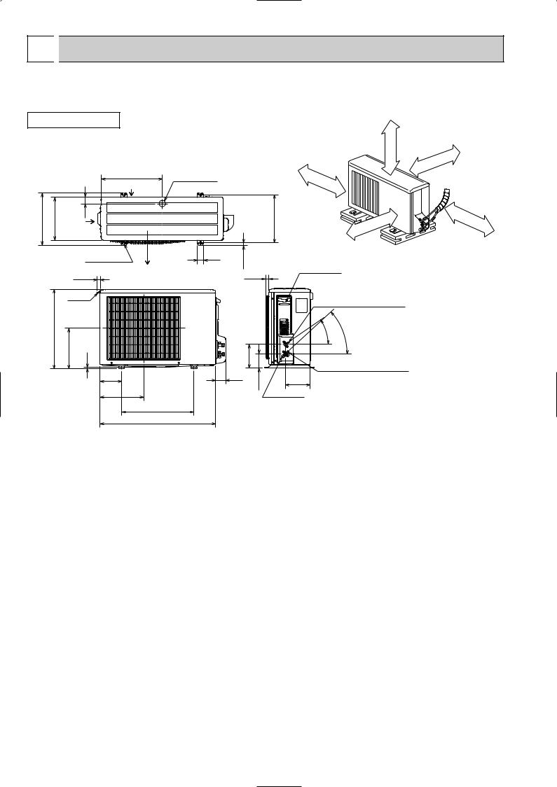
SUZ-A09VR.TH SUZ-A12VR.TH
Unit: mm
OUTDOOR UNIT
REQUIRED SPACE
Basically open 100mm or more without any obstruction in front and on both sides of the unit.
344.5 |
285 |
Air
44 in
400 |
Drain hole [42 |
Air in |
|
Bolt pitch for installation 304~325
100mm |
or |
|
more |
or |
more |
|
200mm
or |
more |
|
100mm
350mm |
or |
|
more |
2 holes 10o21 |
40 |
17.5 |
|
|
|
22.3 |
Air out |
23 |
|
Handle
550
280 |
10 |
|
164.5 |
|
150 |
69 |
99.5 |
|
|
302.5 |
|
|
|
|
500 Bolt pitch for installation
800
Open two sides of left, right, or rear side.
Service panel
Liquid refrigerant pipe joint
Refrigerant pipe (flared) [6.35
- |
- |
35 |
43 |
Gas refrigerant pipe joint
Refrigerant pipe (flared) [9.52
170.5
Service port
12
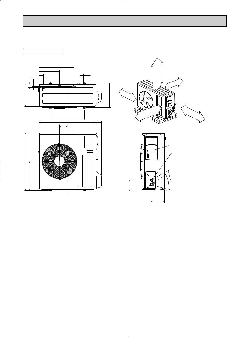
SUZ-A18VR.TH
SUZ-A24VR.TH
OUTDOOR UNIT |
REQUIRED SPACE |
|
|
515 |
|
|
299 |
40 |
|
66 |
|
51 |
34 |
100mm or more |
|
|
|
330 |
|
360 |
500 |
|
840 |
80 Open as a rule |
121 |
500mm or more if the back, |
|
both sides and top are open |
850
430
155 |
90 |
Unit: mm
Open as a rule 500mm or more if the front and both sides are open
100mm or more 200mm or more if there are obstacles to both sides
350mm or more
Service panel
Liquid refrigerant pipe joint Refrigerant pipe (flared) [6.35
- 30
- 35
Gas refrigerant pipe joint Refrigerant pipe
198 (flared) [12.7·····(SUZ-A18VR.TH) [15.88···(SUZ-A24VR.TH)
13
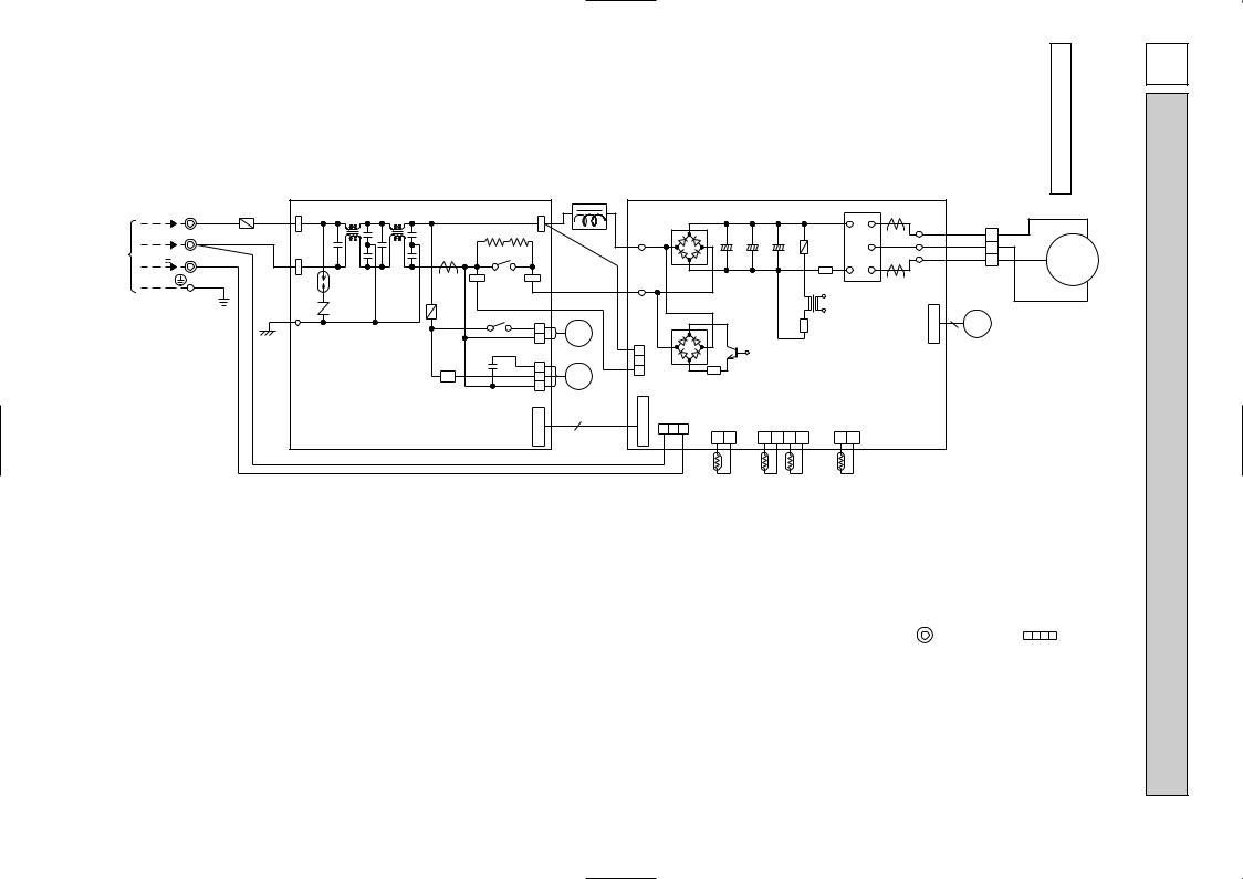
OUTDOOR |
A12VR-SUZ |
A09VR-SUZ |
UNIT |
TH. |
TH. |
|
|
|
|
|
|
|
|
|
|
L61 |
|
|
|
|
|
|
|
|
|
|
|
|
|
|
|
230V~ 2 TB WHT F61WHT TAB61 |
L62 |
L63 |
|
TAB63 BLK |
BLK |
|
DB61 |
|
|
|
|
U |
LD-U |
BLK |
|
|
BLK |
U |
|||||
TO |
|
|
|
|
|
|
R64A R64B |
|
|
|
|
|
|
|
|
|
|
|
||||||
|
|
|
|
|
|
|
|
|
|
|
|
|
|
P |
|
|
1 |
W |
|
|||||
|
N |
BLU |
|
|
|
|
|
|
|
|
+ |
+ |
+ |
|
CT761 LD-V |
WHT |
|
|||||||
INDOOR |
|
|
|
TAB62 |
|
|
|
X64 |
|
|
|
|
|
|
|
F801 |
V |
2 |
RED |
|
|
|||
UNIT |
12V |
3 |
RED |
|
|
|
|
|
LD70 |
|
C62A C62B C61B |
|
N |
|
RED |
3 |
MC |
|
||||||
BLU |
|
|
|
|
|
|
|
LD-W |
|
|||||||||||||||
CONNECTING |
|
|
GRN/YLW |
|
|
|
|
|
|
|
BLK |
|
|
|
|
|
|
W |
CN61 |
|
|
|
||
|
|
|
|
DSA |
CT |
3 |
|
4 |
BLU |
|
|
|
|
|
R61 |
CT781 |
|
|
V |
|||||
|
|
|
|
|
|
|
|
|
|
IPM |
|
|
|
|
||||||||||
|
|
|
|
|
|
|
|
|
|
|
|
|
T801 |
|
|
|
WHT |
|||||||
|
|
|
|
|
|
|
|
|
|
BLU |
LD69 |
|
|
|
|
|
|
|
|
|
|
|
||
|
|
|
|
GRN |
NR61 |
F71 |
|
X63 |
|
|
|
|
|
|
|
C |
6 |
|
|
|
|
|||
|
|
|
|
|
|
|
|
|
|
|
|
|
|
|
|
|
|
|
||||||
|
|
|
|
|
|
|
|
|
|
|
|
|
|
|
|
N |
|
|
|
|
||||
|
|
|
|
LDE |
|
|
|
|
1 |
21S4 |
|
|
|
|
|
IC801 |
|
7 |
LEV |
|
|
|
||
|
|
|
|
|
|
|
|
|
|
|
TR821 |
|
|
|
2 |
|
|
|
|
|
||||
|
|
|
|
|
|
|
|
2 |
|
|
|
|
|
|
4 |
|
|
|
|
|
||||
|
|
|
|
|
|
|
|
|
|
|
|
|
|
|
|
|
|
|
|
|
||||
|
|
|
|
|
|
|
|
CN721 |
|
1 |
|
|
|
|
|
|
|
|
|
|
|
|
|
|
|
|
|
|
|
|
SR61 C65 |
|
1 |
|
2 |
|
|
|
|
|
|
|
|
|
|
|
|
|
|
|
|
|
|
|
|
|
MF |
3 |
|
DB65 |
|
|
|
|
|
|
|
|
|
|
|
|||
|
|
|
|
|
|
|
|
|
2 |
CN800 |
R831 |
|
INVERTER P.C. BOARD |
|
|
|
|
|
||||||
|
|
|
|
|
|
|
|
|
3 |
|
|
|
|
|
|
|
||||||||
|
|
|
|
|
|
|
|
CN771 |
|
C |
|
|
|
|
|
|
|
|
|
|
|
|
|
|
|
|
|
|
|
|
|
|
|
|
|
|
|
|
|
|
|
|
|
|
|
|
|
|
|
|
|
|
|
|
|
|
|
|
C |
7 |
N |
CN601 |
|
|
|
|
|
|
|
|
|
|
|
|
|
|
|
|
|
|
|
|
|
N |
7 |
CN643 |
CN641 |
CN642 |
|
|
|
|
|
|
|||||
14 |
|
|
|
|
|
POWER P.C. BOARD |
7 |
|
2 |
|
3 2 1 |
|
|
|
|
|
|
|||||||
|
|
|
|
|
2 |
|
|
1 2 |
1 2 3 4 |
|
1 2 |
|
|
|
|
|
|
|||||||
|
|
|
|
|
|
5 |
|
|
|
|
|
|
|
|
|
|||||||||
|
|
|
|
|
|
6 |
|
|
|
|
|
|
|
|
|
|
||||||||
|
|
|
|
|
|
|
|
|
|
|
|
|
|
RT65 |
RT61 RT62 |
RT64 |
|
|
|
|
|
|
||
SYMBOL |
NAME |
SYMBOL |
NAME |
SYMBOL |
NAME |
CT,CT761,CT781 |
CURRENT TRANSFORMER |
LEV |
EXPANSION VALVE COIL |
RT65 |
AMBIENT TEMPERATURE THERMISTOR |
|
|
|
|
|
|
C62A,C62B,C61B |
SMOOTHING CAPACITOR |
L61 |
REACTOR |
R61,R831 |
CURRENT-DETECTING RESISTOR |
|
|
|
|
|
|
C65 |
FAN MOTOR CAPACITOR |
L62,L63 |
CMC COIL |
R64A,R64B |
CURRENT-LIMITING RESISTOR |
|
|
|
|
|
|
DB61,DB65 |
DIODE MODULE |
MC |
COMPRESSOR |
SR61 |
SOLID STATE RELAY |
DSA |
SURGE ABSORBER |
MF |
FAN MOTOR |
TB |
TERMINAL BLOCK |
|
|
|
|
|
|
F61 |
FUSE (20A) |
NR61 |
VARISTOR |
TR821 |
SWITCHING POWER TRANSISTOR |
|
|
|
|
|
|
F71,F801 |
FUSE (3.15A) |
RT61 |
DEFROST THERMISTOR |
T801 |
TRANSFORMER |
|
|
|
|
|
|
IC801 |
INTELLIGENT POWER DEVICE |
RT62 |
DISCHARGE TEMPERATURE THERMISTOR |
X63,X64 |
RELAY |
IPM |
POWER TRANSISTOR MODULE |
RT64 |
FIN TEMPERATURE THERMISTOR |
21S4 |
REVERSING VALVE COIL |
|
|
|
|
|
|
NOTE: 1. About the indoor side electric wiring refer to the indoor unit electric wiring diagram for servicing.
2.Use copper conductors only. (For field wiring)
3.Symbols below indicate.
: Terminal block, |
: Connector |
The 12V DC is NOT always against the ground. Terminal 3 has 12V DC against terminal N. However, between Terminal 3 and N, these terminals are NOT electrically insulated by the transformer or other device.
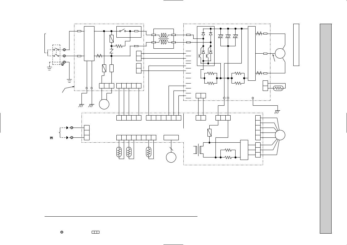
DIAGRAM WIRING 7
|
|
TAB1 |
|
|
|
|
|
|
|
|
|
|
L |
|
|
||
|
|
|
|
|
|
|
|
|
|
|
2 |
|
1 |
|
|||
POWER SUPPLY |
|
|
|
|
|
|
X64 |
4 |
|
|
|
||||||
~/N 230V 50Hz |
|
|
NF |
|
F912 |
|
RED |
|
|
RED |
|||||||
BREAKER |
BRN |
|
|
|
|
R64 |
|
TAB4 |
|
|
|||||||
CIRCUIT |
|
|
|
|
|
|
|
|
|
|
|
|
|
|
|
|
|
TB1 |
|
|
|
|
|
|
|
|
|
|
|
|
3 |
|
4 YLW |
||
|
|
|
|
|
|
|
|
|
CN903 |
|
YLW |
|
|
|
|||
N |
PE |
TAB2 |
CT61 |
|
NR63 |
|
12 |
|
|
BLK |
|||||||
L |
BLU |
|
|
|
|
|
|
|
|
|
|
|
|
|
|||
|
|
|
|
|
|
|
|
|
|
|
|
|
|
|
BLK |
||
|
|
|
|
|
|
|
|
|
|
|
|
|
|
|
|
|
|
|
GRN/YLW |
|
|
LDE1 |
F911 |
3 |
SSR611 |
2 |
3 |
CN902 |
215 |
|
|
|
|
BLK |
|
|
|
|
LDE2 |
1 |
|
|
|
|
|
||||||||
|
|
|
|
|
|
CN912 |
|
CN901 |
|
|
|
|
|
|
|||
P.C.BOARD |
|
GRN |
GRN |
BLU |
BLU |
|
|
|
|
|
|
|
|
|
|
|
|
NOISE FILTER |
|
|
|
|
|
|
|
|
|
|
|
|
|
|
|
||
|
|
|
|
|
21S4 |
|
BLK |
BLK |
BLK |
BLK |
BLK |
|
BLK |
BLK |
BLK |
||
|
|
|
|
|
|
|
|
|
|||||||||
|
|
|
|
ELECTRONIC CONTROL |
1 |
2 |
3 |
|
5 |
1 |
|
5 |
6 |
7 |
|||
15 |
|
|
|
P.C.BOARD |
|
|
|
|
|||||||||
TB2 |
RED |
|
|
|
|
|
CN781 |
|
|
|
CN702 |
|
|||||
3 1 CN601 |
|
|
1 |
2 |
3 |
4 |
|
7 |
8 |
CN795 |
|||||||
12V |
|
BLU |
|
|
|
||||||||||||
TO INDOOR |
3 |
|
|
|
|
|
|
|
|
|
|
|
|
|
|
|
|
UNIT |
|
|
|
|
|
|
|
|
|
CN661 |
|
|
|
|
|
||
CONNECTING |
|
|
|
|
|
|
|
|
|
|
|
|
|
|
|
|
|
|
N |
|
|
|
|
|
|
|
|
|
|
|
|
|
|
|
|
|
|
|
|
|
|
|
|
|
|
|
|
|
|
|
|
6 |
|
|
|
|
|
|
|
|
|
RT62 RT61 |
|
RT68 |
LEV |
|
|||||
|
|
|
|
|
|
|
|
|
|
|
|
||||||
R
S
 7 6 5 4 3 2 1 2 1
PFC
CB1 |
CB2 |
CB3 |
CN5
CN2 |
RS1 |
RS3 |
|
RS2 |
RS4 |
||
|
CN4 |
|
|
|
|
1 |
2 |
LD2 |
|
LD1 |
BLK |
BLK |
RED |
WHT |
|
1 |
2 |
1 |
3 |
CN801 |
|
||||
CN701 |
|
|
|
|
|
F801 |
|
|
|
T801 |
|
|
|
|
|
|
R934A |
||
|
|
R934B |
||
|
N932 |
|
|
|
|
|
|
|
C |
V |
RED |
OUTDOOR |
A18VR - SUZ A24VR - SUZ |
||
|
|
CT2 W |
|
|
|||
|
|
|
|
W |
|
|
|
|
IPM |
|
|
V MC |
UNIT |
TH . TH . |
|
|
|
|
WHT |
U |
|
|
|
|
|
CT1 U |
BLK |
|
|
|
|
|
|
CN3 |
1 2 |
|
|
|
|
LD9 |
POWER |
RT65 |
|
|
|||
|
|
|
|
||||
|
|
BOARD |
|
|
|
|
|
|
|
|
GRN |
|
|
|
|
|
|
5 |
GRY |
|
|
|
|
|
|
PNK |
|
|
|
|
|
|
CN931 |
32 4 |
|
|
|
|
|
|
ORN |
|
|
|
|
||
|
|
|
|
|
|
|
|
|
|
|
BLU |
MF |
|
|
|
|
|
1 |
YLW |
|
|
||
HC932 |
|
21 3 |
RED |
|
|
|
|
|
WHT |
|
|
|
|||
|
|
|
|
|
|
||
|
|
|
BLK |
|
|
|
|
SYMBOL |
NAME |
SYMBOL |
NAME |
SYMBOL |
NAME |
CB1~3 |
SMOOTHING CAPACITOR |
MC |
COMPRESSOR |
RT65 |
FIN TEMP.THERMISTOR |
CT1,2 |
CURRENT TRANSFORMER |
MF |
FAN MOTOR(INNER FUSE) |
RT68 |
OUTDOOR HEAT EXCHANGER |
CT61 |
CURRENT TRANSFORMER |
NF |
NOISE FILTER |
TEMPERATURE THERMISTOR |
|
F801 |
FUSE(250V 3.15A) |
NR63 |
VARISTOR |
SSR61 |
SOLENOID COIL RELAY |
F911 |
FUSE(250V 1A) |
PFC |
POWER FACTOR CONTROLLER |
T801 |
TRANSFORMER |
F912 |
FUSE(250V 3.15A) |
R64 |
RESISTOR |
TB1 |
TERMINAL BLOCK |
HC932 |
FET ARRAY |
R934A,B |
RESISTOR |
TB2 |
TERMINAL BLOCK |
IPM |
POWER TRANSISTOR MODULE |
RS1~4 |
RESISTOR |
X64 |
RELAY |
L |
REACTOR |
RT61 |
DISCHARGE TEMP.THERMISTOR |
21S4 |
REVERSING VALVE SOLENOID COIL |
LEV |
EXPANSION VALVE |
RT62 |
DEFROST TEMP.THERMISTOR |
|
|
NOTES 1. About the indoor side electric wiring refer to the indoor unit electric wiring diagram for servicing.
2.Use copper conductors only(for field wiring).
3.Symbols below indicate.
:Terminal block |
:Connector |
8 
 REFRIGERANT SYSTEM DIAGRAM
SUZ-A09VR.TH |
Unit:mm |
SUZ-A12VR.TH |
|
OUTDOOR UNIT |
|
Refrigerant pipe [9.52 (with heat insulator)
Flared connection
|
4-way valve |
|
|
Muffler |
|
|
|
Stop valve |
|
|
|
(with service port) |
Discharge |
|
Outdoor |
|
temperatuer |
Muffler |
heat |
|
exchanger |
||
|
thermistor |
|
|
|
Defrost |
|
|
|
RT62 |
|
|
|
thermistor |
|
|
|
|
Ambient |
|
|
|
RT61 |
|
|
|
|
temperature |
|
|
|
thermistor |
|
|
|
RT65 |
|
|
|
|
|
Compressor |
|
|
|
|
|
|
|
|
|
Expansion |
|
|
Strainer |
|
|
|
|
|
|
|
|
|||
Flared connection |
|
|
|
|
|
#100 |
|||
|
|
|
|
|
|||||
|
|
|
valve |
|
|
|
|||
|
|
|
|
|
|
|
|
||
|
|
Muffler |
|
|
|
|
R.V. coil |
||
|
|
|
|
|
|
heating ON |
|||
|
|
|
|
|
|
|
|
|
|
|
|
|
|
|
Capillary tube |
|
|
cooling OFF |
|
Refrigerant pipe |
Stop valve |
|
|
||||||
|
|
|
|||||||
[3.0 [2.0 200 |
|
|
|
||||||
[6.35 |
(with strainar) |
|
|
|
|||||
|
|
|
|
|
|||||
(with heat insulator) |
|
|
|
|
|
Refrigerant flow in cooling |
|||
|
|
|
|
|
|
|
|||
|
|
|
|
|
|
|
Refrigerant flow in heating |
||
SUZ-A18VR.TH |
|
|
|
|
|
|
|
Unit:mm |
|
SUZ-A24VR.TH |
|
|
|
|
|
|
|
|
|
OUTDOOR UNIT |
|
|
|
|
|
|
|
|
|
|
|
|
|
|
|
||||
Refrigerant pipe [12.7 (SUZ-A18VR.TH) |
Muffler |
|
|
|
|||||
(with heat insulator) [15.88 (SUZ-A24VR.TH) 4-way valve |
#100 |
|
|
|
|
||||
Stop valve |
|
|
|
|
(with service port) |
|
|
Outdoor |
|
Flared connection |
Discharge |
|
|
|
|
|
heat |
||
|
temperature |
|
exchanger |
|
|
thermistor |
|
Defrost |
|
|
RT61 |
|
thermistor |
|
|
|
|
RT62 |
|
|
Compressor |
|
||
|
|
|
|
Outdoor heat |
|
|
|
|
exchanger |
|
|
|
|
temperature |
|
|
|
|
thermistor |
Flared connection |
|
|
|
RT68 |
Strainer |
LEV |
|
|
|
|
Strainer |
|
||
|
|
R.V. coil |
||
Receiver #100 |
|
#100 |
||
|
|
|
|
heating ON |
Stop valve |
Capillary tube |
|
|
cooling OFF |
|
|
|
||
|
[3.6 [2.4 50 |
|
|
|
Refrigerant pipe [6.35 |
Refrigerant flow in cooling |
(with heat insulator) |
Refrigerant flow in heating |
16
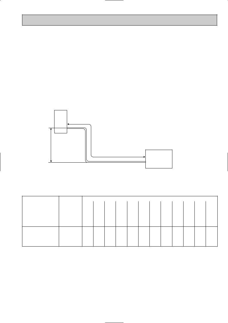
SUZ-A09VR.TH
SUZ-A12VR.TH
MAX. REFRIGERANT PIPING LENGTH
|
Refrigerant piping |
Piping size O.D : mm |
||
Models |
Max. length : m |
|||
|
|
|||
|
|
|
|
|
|
A |
Gas |
Liquid |
|
SUZ-A09VR.TH |
20 |
9.52 |
6.35 |
|
SUZ-A12VR.TH |
||||
|
|
|
||
|
|
|
|
|
MAX. HEIGHT DIFFERENCE
Indoor
unit (SLZ/SEZ)
wMax. Height difference 12m
Refrigerant Piping
Max. length
A
Outdoor unit
w Height difference should be within 12m regardless of which unit, indoor or outdoor position is high.
ADDITIONAL REFRIGERANT CHARGE (R410A:g)
Models |
Outdoor unit |
|
|
|
Refrigerant piping length (one way) |
|
|
|
||||||
precharged |
5m |
6m |
7m |
8m |
9m |
10m |
11m |
12m |
13m |
14m |
15m |
20m |
||
|
||||||||||||||
SUZ-A09VR.TH |
800 |
0 |
0 |
0 |
90 |
120 |
150 |
180 |
210 |
240 |
270 |
300 |
450 |
|
SUZ-A12VR.TH |
900 |
0 |
0 |
0 |
90 |
120 150 180 210 240 270 300 450 |
Calculation : Xg=30g/mo(Refrigerant piping length(m) - 5)
17
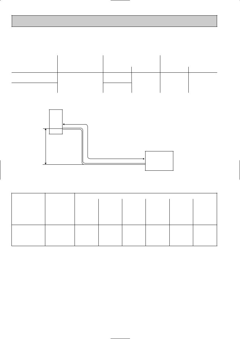
SUZ-A18VR.TH
SUZ-A24VR.TH
MAX. REFRIGERANT PIPING LENGTH
|
Refrigerant piping |
Piping size O.D : mm |
Length of connecting pipe : m |
|||
Model |
Max. length : m |
|||||
|
|
|
|
|||
|
A |
Gas |
Liquid |
Indoor unit |
Outdoor unit |
|
SUZ-A18VR.TH |
|
12.7 |
|
Gas 0.43 |
Gas 0 |
|
|
30 |
|
6.35 |
|||
|
|
Liquid 0.5 |
Liquid 0 |
|||
SUZ-A24VR.TH |
|
15.88 |
|
|||
|
|
|
|
|||
|
|
|
|
|
|
|
MAX. HEIGHT DIFFERENCE
Indoor
unit (SLZ/SEZ)
wMax. Height difference 15m
Refrigerant Piping
Max. length
A
Outdoor unit
w Height difference should be within 15m regardless of which unit, indoor or outdoor position is high.
ADDITIONAL REFRIGERANT CHARGE(R410A : g)
Model |
Outdoor unit |
|
|
Refrigerant piping length (one way) |
|
|
||
|
|
|
|
|
|
|||
precharged |
7m |
10m |
15m |
20m |
25m |
30m |
||
|
||||||||
SUZ-A18VR.TH |
1,800 |
0 |
60 |
160 |
260 |
360 |
460 |
|
SUZ-A24VR.TH |
1,800 |
0 |
60 |
160 |
260 |
360 |
460 |
Calculation : Xg=20g/m (Refrigerant piping length (m)–7)
18
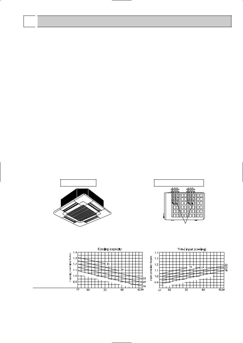
9 
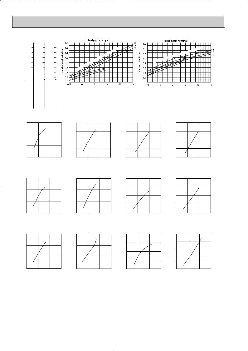
 PERFORMANCE CURVES
●SLZ-A09AR.TH / SUZ-A09VR.TH
●SLZ-A12AR.TH / SUZ-A12VR.TH
●SLZ-A18AR.TH / SUZ-A18VR.TH
The standard data contained in these specifications apply only to the operation of the air conditioner under normal condition. Operating conditions vary according to the areas where these units are installed. The following information has been provided to clarify the operating characteristics of the air conditioner under the conditions indicated by the performance curve.
(1) GUARANTEED VOLTAGE
Rated voltage : ±10% (207~253V), 50Hz
(2) AIR FLOW
Air flow should be set at MAX.
(3) MAIN READINGS
COOLING |
|
HEATING |
|
||
(1) |
Indoor intake air wet-bulb temperature : |
W.B. ˚C |
(1) |
Indoor intake air dry-bulb temperature : |
D.B. ˚C |
(2) |
Indoor outlet air wet-bulb temperature : |
W.B. ˚C |
(2) |
Indoor outlet air dry-bulb temperature : |
D.B. ˚C |
(3) |
Outdoor intake air dry-bulb temperature : D.B. ˚C |
(3) |
Outdoor intake air wet-bulb temperature : W.B. ˚C |
||
(4) Total input : W |
|
(4) Total input : W |
|
||
Indoor air wet/dry-bulb temperature difference on the side of the chart on page shows the difference between the indoor intake air wet/dry-bulb temperature and the indoor outlet air wet/dry-bulb temperature for your reference at service.
How to measure the indoor air wet-bulb/dry-bulb temperature difference
1.Attach at least 2 sets of wet-and-dry-bulb thermometers to the indoor air inlet as shown in the figure, and at least 2 sets of wet-and-dry-bulb thermometers to the indoor air outlet. The thermometers must be attached to the position where air speed is high.
2.Attach at least 2 sets of wet-and-dry-bulb thermometers to the outdoor air inlet. Cover the thermometers to prevent direct rays of the sun.
3.Check that the air filter is cleaned.
4.Open windows and doors of the room.
5.Press the EMERGENCY OPERATION switch once to start the COOL(HEAT) MODE.
6.When system stabilizes after more than 15 minutes, measure temperature and take an average temperature.
7.10 minutes later, measure temperature again and check that the temperature does not change.
INDOOR UNIT |
OUTDOOR UNIT |
Wet-and dry-bulb thermometers
BACK VIEW
Indoor air Wet-bulb temperature difference (degree)
6.6 |
|
|
|
8.0 |
|
|
|
|
10.8 |
|
|
|
|
|
|
|
|
|
|
|
|
|
|||
6.1 |
|
|
|
7.5 |
|
|
|
|
10.0 |
|
|
|
|
|
|
|
|
|
|
|
|
|
|||
5.6 |
|
|
|
6.9 |
|
|
|
|
9.2 |
|
|
|
|
|
|
|
|
|
|
|
|
|
|||
|
|
|
|
|
|
|
|
|
|
|||
5.2 |
|
|
|
6.3 |
|
|
|
|
8.5 |
|
|
|
|
|
|
|
|
|
|
|
|
|
|||
|
|
|
|
|
|
|
|
|
|
|||
4.7 |
|
|
|
5.7 |
|
|
|
|
7.7 |
|
|
|
|
|
|
|
|
|
|
|
|
|
|||
|
|
|
|
|
|
|
|
|
|
|||
4.2 |
|
|
|
5.2 |
|
|
|
|
6.9 |
|
|
|
|
|
|
|
|
|
|
|
|
|
|||
|
|
|
|
|
|
|
|
|
|
|||
|
|
|
|
|
|
|
|
|
|
|
|
|
A09VR.TH |
frequency 57Hz |
|
A12VR.TH |
frequency 67Hz |
|
A18VR.TH |
frequency 75Hz |
|||||
SUZ- |
Rated |
|
SUZ- |
Rated |
|
SUZ- |
Rated |
|||||
Indoor |
intake |
|
|
|
air |
|
Wet- |
|
bulb |
|
temperature ( |
|
:) |
Outdoor intake air Dry-bulb temperature (:)
|
|
) |
|
|
(: |
|
-bulb |
temperature |
|
|
|
air |
Wet |
|
intake |
|
|
Indoor |
|
|
Outdoor intake air Dry-bulb temperature (:)
19
Indoor air Dry-bulb temperature difference (degree)
20.423.6 28.2
18.921.8 26.0
17.320.0 23.9
15.718.2 21.7
14.216.3 19.5
12.614.5 17.4
11.0 |
|
|
12.7 |
|
|
15.2 |
|||
|
|
|
|||||||
9.4 |
|
|
10.9 |
|
|
13.0 |
|||
|
|
|
|||||||
A09VR.TH |
frequency 75Hz |
A12VR.TH |
frequency 76Hz |
|
|
A18VR.TH |
frequency 65Hz |
||
SUZ- |
Rated |
SUZ- |
Rated |
|
|
SUZ- |
Rated |
||
|
|
|
) |
|
|
|
(: |
|
|
-bulb |
temperature |
|
|
|
|
|
air |
Dry |
|
intake |
|
|
|
|
|
|
|
Indoor |
|
|
|
Outdoor intake air Wet-bulb temperature (:)
|
|
) |
|
|
(: |
|
-bulb |
temperature |
|
|
|
air |
Dry |
|
intake |
|
|
Indoor |
|
|
Outdoor intake air Wet-bulb temperature (:)
NOTE:The above curves are for the heating operation without any frost.
SUZ-A09VR.TH
Correction of Cooling capacity
|
1.5 |
|
|
|
factors |
1.0 |
|
|
|
correction |
|
|
|
|
0.5 |
|
|
|
|
Capacity |
|
|
|
|
|
|
|
|
|
|
0.0 |
50 |
100 |
150(Hz) |
|
0 |
The operational frequency of compressor
SUZ-A09VR.TH
Correction of Cooling total input
2.0 |
|
|
|
factors |
|
|
|
1.5 |
|
|
|
correction |
|
|
|
1.0 |
|
|
|
Input |
|
|
|
0.5 |
|
|
|
0.0 |
50 |
100 |
150(Hz) |
0 |
The operational frequency of compressor
SUZ-A09VR.TH
Correction of Heating capacity
2.0 |
|
|
|
factors1.5 |
|
|
|
correction |
|
|
|
1.0 |
|
|
|
Capacity |
|
|
|
0.5 |
|
|
|
0.0 |
50 |
100 |
150(Hz) |
0 |
The operational frequency of compressor
SUZ-A09VR.TH
Correction of Heating total input
2.0
factors 1.5 correction 1.0 Input 0.5
0.0
0 |
50 |
100 |
150(Hz) |
The operational frequency of compressor
SUZ-A12VR.TH
|
Correction of Cooling capacity |
|||
|
1.5 |
|
|
|
factors |
|
|
|
|
correction |
1.0 |
|
|
|
|
|
|
|
|
Capacity |
0.5 |
|
|
|
|
0.0 |
50 |
100 |
150(Hz) |
|
0 |
|||
The operational frequency of compressor
SUZ-A12VR.TH
Correction of Cooling total input
1.5 |
|
|
|
factors1.0 |
|
|
|
correction0.5 |
|
|
|
Input |
|
|
|
0.0 |
50 |
100 |
150(Hz) |
0 |
The operational frequency of compressor
SUZ-A12VR.TH
Correction of Heating capacity
2.0 |
|
|
|
factors1.5 |
|
|
|
correction |
|
|
|
1.0 |
|
|
|
Capacity |
|
|
|
0.5 |
|
|
|
0.0 |
50 |
100 |
150(Hz) |
0 |
The operational frequency of compressor
SUZ-A12VR.TH
Correction of Heating total input
2.0 |
|
|
|
factors |
|
|
|
1.5 |
|
|
|
correction |
|
|
|
1.0 |
|
|
|
Input |
|
|
|
0.5 |
|
|
|
0.0 |
50 |
100 |
150(Hz) |
0 |
The operational frequency of compressor
SUZ-A18VR.TH
|
Correction of Cooling capacity |
|||
|
1.5 |
|
|
|
factors |
|
|
|
|
correction |
1.0 |
|
|
|
Capacity |
0.5 |
|
|
|
|
|
|
|
|
|
0.0 |
50 |
100 |
150(Hz) |
|
0 |
|||
The operational frequency of compressor
SUZ-A18VR.TH
Correction of Cooling total input
1.5 |
|
|
|
factors1.0 |
|
|
|
correction0.5 |
|
|
|
Input |
|
|
|
0.0 |
50 |
100 |
150(Hz) |
0 |
The operational frequency of compressor
SUZ-A18VR.TH
Correction of Heating capacity
2.0 |
|
|
|
factors1.5 |
|
|
|
correction |
|
|
|
1.0 |
|
|
|
Capacity |
|
|
|
0.5 |
|
|
|
0.0 |
50 |
100 |
150(Hz) |
0 |
The operational frequency of compressor
SUZ-A18VR.TH
Correction of Heating total input
2.5 |
|
|
|
factors |
|
|
|
2.0 |
|
|
|
correction |
|
|
|
1.5 |
|
|
|
1.0 |
|
|
|
Input |
|
|
|
0.5 |
|
|
|
0.0 |
50 |
100 |
150(Hz) |
0 |
The operational frequency of compressor
OUTDOOR LOW PRESSURE AND OUTDOOR UNIT CURRENT
<How to operate fixed-frequency operation (Test run operation)>
1.Press the EMERGENCY OPERATION switch to COOL or HEAT mode.
2.Test run operation starts and continue to operate for 30 minutes.
3.Compressor starts at rated frequency in COOL mode or 58Hz in HEAT mode.
4.Indoor fan operates at High speed.
5.After 30 minutes, test run operation finishes and EMERGENCY OPERATION starts.
6.To cancel test run operation (EMERGENCY OPERATION), press the EMERGENCY OPERATION switch or any button on remote controller.
NOTE : The unit of pressure has been changed to MPa on the international system of units (SI unit system). The conversion factor is: 1(MPa [Gauge]) =10.2(kgf/f [Gauge])
20
OUTDOOR LOW PRESSURE AND OUTDOOR UNIT CURRENT
COOL operation
1 Both indoor and outdoor unit are under the |
Dry-bulb temperature |
Relative humidity(%) |
|
|
|
||
same temperature/humidity condition. |
20 |
50 |
|
2 Air flow : High speed |
|
|
|
25 |
60 |
||
3 Operational frequency : 57Hz(SUZ-A09VR.TH) |
|||
|
|
||
67Hz(SUZ-A12VR.TH) |
30 |
70 |
|
75Hz(SUZ-A18VR.TH) |
|
|
|
|
|
SUZ-A09VR.TH
(kgf/F [Gauge]) (MPa [Gauge]) |
|
|
|
|
|
|
|||||||||
pressure |
14 |
|
1.4 |
|
|
|
|
|
|
|
|
|
|
|
|
|
|
|
|
|
|
|
|
|
|
|
|
||||
10 |
1.0 |
|
|
|
|
|
|
|
|
|
|
|
|||
|
12 |
|
1.2 |
|
|
|
|
|
|
|
|
|
|
|
|
|
|
|
|
|
|
|
|
|
|
|
|
57Hz |
|
|
|
low |
8 |
|
0.8 |
|
|
|
|
|
|
|
|
|
|
|
|
Outdoor |
|
|
|
|
|
|
|
|
|
|
|
|
|||
6 |
|
0.6 |
|
|
|
|
|
|
|
|
|
|
|
||
|
|
|
|
|
|
|
|
|
|
|
|
|
|||
|
4 |
|
0.4 |
|
|
|
|
|
|
|
|
|
|
|
|
|
|
|
|
|
|
|
|
|
|
|
|
|
|||
|
2 |
|
0.2 |
|
|
|
|
|
|
|
|
|
|
|
|
|
|
18 20 |
25 |
30 32 |
35(˚C) |
||||||||||
|
|
15 |
|||||||||||||
|
|
|
|
|
|
50 |
60 |
70 |
(%) |
||||||
Ambient temperature(˚C) Ambient humidity(%)
SUZ-A12VR.TH
(kgf/F [Gauge]) (MPa [Gauge]) |
|
|
|
|
|
|
|||||||||
|
14 |
|
1.4 |
|
|
|
|
|
|
|
|
|
|
|
|
pressure |
|
|
|
|
|
|
|
|
|
|
|
67Hz |
|
|
|
10 |
1.0 |
|
|
|
|
|
|
|
|
|
|
|
|||
low |
12 |
|
1.2 |
|
|
|
|
|
|
|
|
|
|
|
|
|
|
|
|
|
|
|
|
|
|
|
|
||||
8 |
|
0.8 |
|
|
|
|
|
|
|
|
|
|
|
||
|
|
|
|
|
|
|
|
|
|
|
|
||||
Outdoor |
|
|
|
|
|
|
|
|
|
|
|
|
|||
6 |
|
0.6 |
|
|
|
|
|
|
|
|
|
|
|
||
|
|
|
|
|
|
|
|
|
|
|
|
|
|||
|
4 |
|
0.4 |
|
|
|
|
|
|
|
|
|
|
|
|
|
|
|
|
|
|
|
|
|
|
|
|
|
|||
|
2 |
|
0.2 |
|
|
|
|
|
|
|
|
|
|
|
|
|
|
18 20 |
25 |
30 32 |
35(˚C) |
||||||||||
|
|
15 |
|||||||||||||
|
|
|
|
|
|
50 |
60 |
70 |
(%) |
||||||
Ambient temperature(˚C) Ambient humidity(%)
|
|
|
|
|
SUZ-A18VR.TH |
|
|
|||||||
(kgf/F [Gauge]) (MPa [Gauge]) |
|
|
|
|
|
|||||||||
pressure |
14 |
|
1.4 |
|
|
|
|
|
|
|
|
|
|
|
|
|
|
|
|
|
|
|
|
|
|
||||
10 |
1.0 |
|
|
|
|
|
|
|
|
|
|
|||
|
|
|
|
|
|
|
|
|
|
|||||
low |
12 |
|
1.2 |
|
|
|
|
|
|
|
75Hz |
|
||
|
|
|
|
|
|
|
|
|
||||||
8 |
|
0.8 |
|
|
|
|
|
|
|
|
|
|
||
|
|
|
|
|
|
|
|
|
|
|
||||
Outdoor |
|
|
|
|
|
|
|
|
|
|
|
|||
6 |
|
0.6 |
|
|
|
|
|
|
|
|
|
|
||
|
|
|
|
|
|
|
|
|
|
|
|
|||
|
4 |
|
0.4 |
|
|
|
|
|
|
|
|
|
|
|
|
|
|
|
|
|
|
|
|
|
|
|
|||
|
2 |
|
0.2 |
|
|
|
|
|
|
|
|
|
|
|
|
|
18 20 |
25 |
30 32 |
35(˚C) |
|||||||||
|
|
15 |
||||||||||||
|
|
|
|
|
|
50 |
60 |
70 |
|
(%) |
||||
Ambient temperature(˚C) Ambient humidity(%)
SUZ-A09VR.TH
|
6 |
|
|
|
|
|
|
|
|
current(A) |
|
|
|
|
|
|
67Hz |
|
|
|
|
|
|
|
|
|
|
||
5 |
|
|
|
|
|
|
|
|
|
|
|
|
|
|
|
|
|
|
|
unit |
4 |
|
|
|
|
|
|
|
|
|
|
|
|
|
|
|
|
||
|
|
|
|
|
|
|
|
|
|
Outdoor |
3 |
|
|
|
|
|
|
|
|
|
|
|
|
|
|
|
|
|
|
|
2 |
|
|
|
|
|
|
|
|
|
|
18 20 |
25 |
3032 35(˚C) |
|||||
|
15 |
||||||||
|
|
|
50 |
60 |
70 |
(%) |
|||
Ambient temperature(˚C) Ambient humidity(%)
SUZ-A12VR.TH
current(A) |
4 |
|
|
|
|
|
|
|
|
|
|
|
|
|
|
|
|
||
3.5 |
|
|
|
|
|
|
|
|
|
unit |
|
|
|
|
|
|
57Hz |
|
|
|
|
|
|
|
|
|
|
||
3 |
|
|
|
|
|
|
|
|
|
Outdoor |
|
|
|
|
|
|
|
|
|
2.5 |
|
|
|
|
|
|
|
|
|
|
|
|
|
|
|
|
|
|
|
|
2 |
|
|
|
|
|
|
|
|
|
|
18 20 |
25 |
3032 35(˚C) |
|||||
|
15 |
||||||||
|
|
|
50 |
60 |
70 |
(%) |
|||
Ambient temperature(˚C) Ambient humidity(%)
SUZ-A18VR.TH
current(A) |
9.0 |
|
|
|
|
|
|
|
|
|
|
|
|
|
|
|
|
75Hz |
|
||
8.0 |
|
|
|
|
|
|
|
|
||
|
|
|
|
|
|
|
|
|
||
unit |
|
|
|
|
|
|
|
|
|
|
|
|
|
|
|
|
|
|
|
||
7.0 |
|
|
|
|
|
|
|
|
|
|
Outdoor |
|
|
|
|
|
|
|
|
|
|
6.0 |
|
|
|
|
|
|
|
|
|
|
|
|
|
|
|
|
|
|
|
|
|
|
5.0 |
|
|
|
|
|
|
|
|
|
|
|
18 20 |
25 |
3032 35(˚C) |
||||||
|
15 |
|||||||||
|
|
|
50 |
60 |
70 |
(%) |
||||
Ambient temperature(˚C) Ambient humidity(%)
HEAT operation
Condition indoor: Dry bulb temperature 20.0°C Wet bulb temperature 14.5°C
Condition outdoor: Dry bulb temperature 2,7,15,20.0°C Wet bulb temperature 1,6,12,14.5°C
Outdoor unit current (A)
SUZ-A09VR.TH
3.0
58Hz
2.5
2.0
1.5
1.0
0.5
0.0
2 5 |
10 15 20 |
25(:) |
Ambient temperature(˚C) |
|
|
Outdoor unit current (A)
SUZ-A12VR.TH
4.0
3.5
58Hz
3.0
2.5
2.0
1.5
1.0
2 5 |
10 |
15 |
20 |
25(:) |
Ambient temperature(˚C) |
|
|||
Outdoor unit current (A)
SUZ-A18VR.TH
7.0
6.0
58Hz
5.0
4.0
3.0
2.0
1.0
2 5 |
10 |
15 20 |
25(:) |
Ambient temperature(˚C)
21
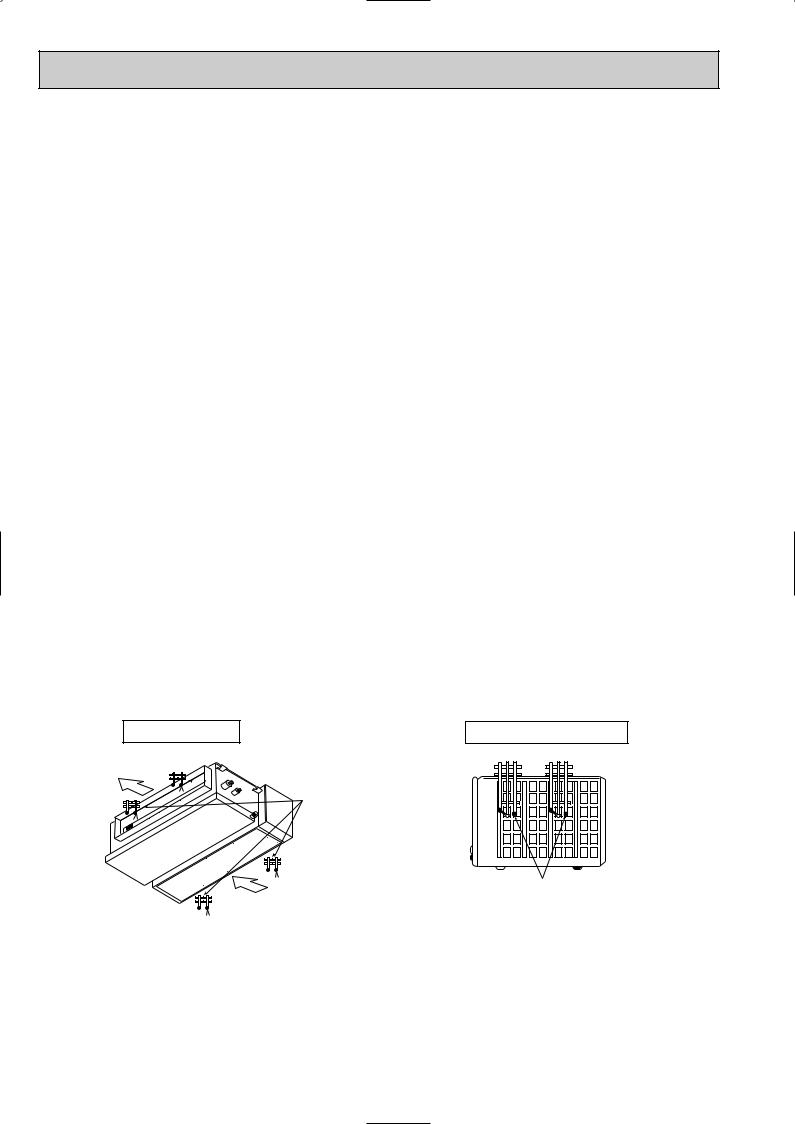
●SEZ-A09CR.W / SUZ-A09VR.TH
●SEZ-A12AR.TH / SUZ-A12VR.TH
●SEZ-A18AR.TH / SUZ-A18VR.TH
●SEZ-A24AR.TH / SUZ-A24VR.TH
The standard data contained in these specifications apply only to the operation of the air conditioner under normal condition. Operating conditions vary according to the areas where these units are installed. The following information has been provided to clarify the operating characteristics of the air conditioner under the conditions indicated by the performance curve.
(1) GUARANTEED VOLTAGE
Rated voltage : ±10% (207~253V), 50Hz
(2) AIR FLOW
Air flow should be set at MAX.
(3) MAIN READINGS
COOLING |
HEATING |
|
||
(1) |
Indoor intake air wet-bulb temperature : W.B.˚C |
(1) |
Indoor intake air dry-bulb temperature : |
D.B.˚C |
(2) |
Indoor outlet air wet-bulb temperature : W.B.˚C |
(2) |
Indoor outlet air dry-bulb temperature : |
D.B.˚C |
(3) |
Outdoor intake air dry-bulb temperature : D.B.˚C |
(3) |
Outdoor intake air wet-bulb temperature : W.B.˚C |
|
(4) Total input : W |
(4) Total input : W |
|
||
Indoor air wet/dry-bulb temperature difference on the side of the chart on page shows the difference between the
indoor intake air wet/dry-bulb temperature and the indoor outlet air wet/dry-bulb temperature for your reference at service.
How to measure the indoor air wet-bulb/dry-bulb temperature difference
1.Attach at least 2 sets of wet-and-dry-bulb thermometers to the indoor air inlet as shown in the figure, and at least 2 sets of wet-and-dry-bulb thermometers to the indoor air outlet. The thermometers must be attached to the position where air speed is high.
2.Attach at least 2 sets of wet-and-dry-bulb thermometers to the outdoor air inlet. Cover the thermometers to prevent direct rays of the sun.
3.Check that the air filter is cleaned.
4.Open windows and doors of the room.
5.Press the TEST button twice to start the COOL(HEAT) MODE.
6.When system stabilizes after more than 15 minutes, measure temperature and take an average temperature.
7.10 minutes later, measure temperature again and check that the temperature does not change.
INDOOR UNIT |
OUTDOOR UNIT |
Air outlet
 Wet-and dry-bulb thermometers
Air inlet
wThe picture is SEZ-A12,18, 24AR. SEZ-A09CR is similar to SEZ-A12, 18, 24AR.
Wet-and dry-bulb thermometers BACK VIEW
22
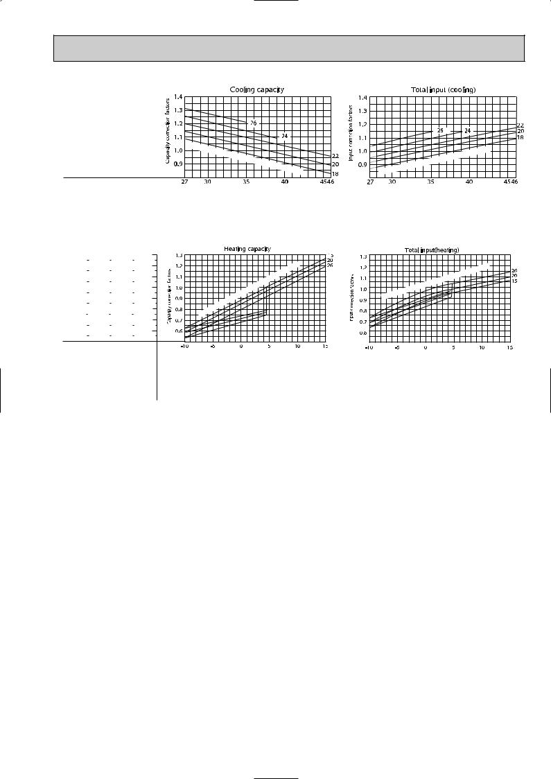
Indoor air Wet-bulb temperature difference (degree)
Indoor air Dry-bulb temperature difference (degree)
7.9 |
|
|
|
7.8 |
|
|
|
8.4 |
|
|
|
8.6 |
|
|
|
|
|
|
|
|
|
|
|
|
|
|
|
||||
7.4 |
|
|
|
7.2 |
|
|
|
7.8 |
|
|
|
8.0 |
|
|
|
|
|
|
|
|
|
|
|
|
|
|
|
||||
6.8 |
|
|
|
6.7 |
|
|
|
7.2 |
|
|
|
7.4 |
|
|
|
|
|
|
|
|
|
|
|
|
|
|
|
||||
|
|
|
|
|
|
|
|
|
|
|
|
||||
6.2 |
|
|
|
6.1 |
|
|
|
6.6 |
|
|
|
6.8 |
|
|
|
|
|
|
|
|
|
|
|
|
|
|
|
||||
|
|
|
|
|
|
|
|
|
|
|
|
||||
5.7 |
|
|
|
5.6 |
|
|
|
6.0 |
|
|
|
6.2 |
|
|
|
|
|
|
|
|
|
|
|
|
|
|
|
||||
|
|
|
|
|
|
|
|
|
|
|
|
||||
5.1 |
|
|
|
5.0 |
|
|
|
5.4 |
|
|
|
5.5 |
|
|
|
|
|
|
|
|
|
|
|
|
|
|
|
||||
|
|
|
|
|
|
|
|
|
|
|
|
||||
|
|
|
|
|
|
|
|
|
|
|
|
|
|
|
|
A09VR.TH |
frequency 57Hz |
|
A12VR.TH |
frequency 67Hz |
|
A18VR.TH |
frequency 80Hz |
|
A24VR.TH |
frequency 87Hz |
|||||
SUZ- Rated |
|
SUZ- Rated |
|
SUZ- Rated |
|
SUZ- Rated |
|||||||||
25.2 |
|
22.1 |
|
24.5 |
|
25.3 |
|
||||||||
|
|
|
|||||||||||||
23.2 |
|
20.4 |
|
22.6 |
|
23.3 |
|
||||||||
|
|
|
|||||||||||||
21.3 |
|
18.7 |
|
20.7 |
|
21.4 |
|
||||||||
|
|
|
|||||||||||||
19.4 |
|
17.0 |
|
18.9 |
|
19.4 |
|
||||||||
|
|
|
|||||||||||||
17.4 |
|
15.3 |
|
17.0 |
|
17.5 |
|
||||||||
|
|
|
|||||||||||||
15.5 |
|
13.6 |
|
15.1 |
|
15.5 |
|
||||||||
|
|
|
|||||||||||||
13.6 |
|
11.9 |
|
13.2 |
|
13.6 |
|
||||||||
|
|
|
|||||||||||||
11.6 |
|
10.2 |
|
11.3 |
|
11.7 |
|
||||||||
|
|
|
|||||||||||||
A09VR.TH |
frequency 75Hz |
|
A12VR.TH |
frequency 76Hz |
|
A18VR.TH |
frequency 80Hz |
|
A24VR.TH |
frequency 96Hz |
|||||
SUZ- |
Rated |
|
SUZ- |
Rated |
|
SUZ- |
Rated |
|
SUZ- |
Rated |
|||||
|
|
|
|
|
|
|
|
|
|
|
|
|
|
|
|
Indoor |
intake |
|
|
|
air |
|
Wet- |
|
bulb |
|
temperature ( |
|
:) |
Outdoor intake air Dry-bulb temperature (:)
|
|
|
) |
|
|
|
(: |
|
|
-bulb |
temperature |
|
|
|
|
|
air |
Dry |
|
intake |
|
|
|
|
|
|
|
Indoor |
|
|
|
Outdoor intake air Wet-bulb temperature (:)
|
|
) |
|
|
(: |
|
-bulb |
temperature |
|
|
|
air |
Wet |
|
intake |
|
|
Indoor |
|
|
Outdoor intake air Dry-bulb temperature (:)
|
|
) |
|
|
(: |
|
-bulb |
temperature |
|
|
|
air |
Dry |
|
intake |
|
|
Indoor |
|
|
Outdoor intake air Wet-bulb temperature (:)
NOTE:The above curves are for the heating operation without any frost.
23

Capacity correction factors
SUZ-A09VR.TH
Correction of Cooling capacity
1.5
1.0
0.5
0.0 |
50 |
100 |
150(Hz) |
0 |
Input correction factors
SUZ-A09VR.TH
Correction of Cooling total input
2.0
1.5
1.0
0.5
0.0 |
50 |
100 |
150(Hz) |
0 |
Capacity correction factors
|
SUZ-A09VR.TH |
|
|
|
SUZ-A09VR.TH |
|
||
Correction of Heating capacity |
|
Correction of Heating total input |
||||||
2.0 |
|
|
|
|
2.0 |
|
|
|
1.5 |
|
|
|
factors |
1.5 |
|
|
|
1.0 |
|
|
|
correction |
1.0 |
|
|
|
|
|
|
|
|
|
|
||
0.5 |
|
|
|
Input |
0.5 |
|
|
|
|
|
|
|
|
|
|
||
0.0 |
50 |
100 |
150(Hz) |
|
0.0 |
50 |
100 |
150(Hz) |
0 |
|
0 |
||||||
The operational frequency of compressor |
The operational frequency of compressor |
The operational frequency of compressor |
The operational frequency of compressor |
Capacity correction factors
SUZ-A12VR.TH
Correction of Cooling capacity
1.5
1.0
0.5
0.0 |
50 |
100 |
150(Hz) |
0 |
Input correction factors
|
|
SUZ-A12VR.TH |
|
|
|
|
|
SUZ-A12VR.TH |
|
|
|
|
|
SUZ-A12VR.TH |
|
|
|||||||||
Correction of Cooling total input |
|
|
Correction of Heating capacity |
|
Correction of Heating total input |
||||||||||||||||||||
1.5 |
|
|
|
|
|
|
|
factorscorrectionCapacity |
2.0 |
|
|
|
|
|
|
|
factorscorrectionInput |
2.0 |
|
|
|
|
|
|
|
1.0 |
|
|
|
|
|
|
|
1.5 |
|
|
|
|
|
|
|
1.5 |
|
|
|
|
|
|
|
||
|
|
|
|
|
|
|
|
|
|
|
|
|
|
|
|
|
|
|
|
|
|
|
|||
|
|
|
|
|
|
|
|
1.0 |
|
|
|
|
|
|
|
|
1.0 |
|
|
|
|
|
|
|
|
|
|
|
|
|
|
|
|
|
|
|
|
|
|
|
|
|
|
|
|
|
|
|
|||
0.5 |
|
|
|
|
|
|
|
|
|
|
|
|
|
|
|
|
|
|
|
|
|
|
|
||
|
|
|
|
|
|
|
|
|
|
|
|
|
|
|
|
|
|
|
|
|
|
|
|||
|
|
|
|
|
|
|
|
0.5 |
|
|
|
|
|
|
|
|
0.5 |
|
|
|
|
|
|
|
|
|
|
|
|
|
|
|
|
|
|
|
|
|
|
|
|
|
|
|
|
|
|
|
|||
0.0 |
|
|
|
|
|
|
|
|
|
|
|
|
|
|
|
|
|
|
|
|
|
|
|
||
|
|
|
|
|
|
|
|
|
|
|
|
|
|
|
|
|
|
|
|
|
|
|
|||
|
|
|
|
|
|
|
|
0.0 |
|
|
|
|
|
|
|
|
0.0 |
|
|
|
|
|
|
|
|
0 |
50 |
100 |
150(Hz) |
|
0 |
50 |
100 |
150(Hz) |
|
0 |
50 |
100 |
150(Hz) |
||||||||||||
The operational frequency of compressor |
The operational frequency of compressor |
The operational frequency of compressor |
The operational frequency of compressor |
Capacity correction factors
SUZ-A18VR.TH
Correction of Cooling capacity
1.5
1.0
0.5
0.0 |
50 |
100 |
150(Hz) |
0 |
Input correction factors
|
|
SUZ-A18VR.TH |
|
|
|
|
|
SUZ-A18VR.TH |
|
|
|
|
|
SUZ-A18VR.TH |
|
|
|||||||||
Correction of Cooling total input |
|
|
Correction of Heating capacity |
|
Correction of Heating total input |
||||||||||||||||||||
1.5 |
|
|
|
|
|
|
|
factorscorrectionCapacity |
2.0 |
|
|
|
|
|
|
|
factorscorrectionInput |
2.0 |
|
|
|
|
|
|
|
1.0 |
|
|
|
|
|
|
|
1.5 |
|
|
|
|
|
|
|
1.5 |
|
|
|
|
|
|
|
||
|
|
|
|
|
|
|
|
|
|
|
|
|
|
|
|
|
|
|
|
|
|
|
|||
|
|
|
|
|
|
|
|
1.0 |
|
|
|
|
|
|
|
|
1.0 |
|
|
|
|
|
|
|
|
|
|
|
|
|
|
|
|
|
|
|
|
|
|
|
|
|
|
|
|
|
|
|
|||
0.5 |
|
|
|
|
|
|
|
|
|
|
|
|
|
|
|
|
|
|
|
|
|
|
|
||
|
|
|
|
|
|
|
|
|
|
|
|
|
|
|
|
|
|
|
|
|
|
|
|||
|
|
|
|
|
|
|
|
0.5 |
|
|
|
|
|
|
|
|
0.5 |
|
|
|
|
|
|
|
|
|
|
|
|
|
|
|
|
|
|
|
|
|
|
|
|
|
|
|
|
|
|
|
|||
0.0 |
|
|
|
|
|
|
|
|
|
|
|
|
|
|
|
|
|
|
|
|
|
|
|
||
|
|
|
|
|
|
|
|
|
|
|
|
|
|
|
|
|
|
|
|
|
|
|
|||
|
|
|
|
|
|
|
|
0.0 |
|
|
|
|
|
|
|
|
0.0 |
|
|
|
|
|
|
|
|
0 |
50 |
100 |
150(Hz) |
|
0 |
50 |
100 |
150(Hz) |
|
0 |
50 |
100 |
150(Hz) |
||||||||||||
The operational frequency of compressor |
The operational frequency of compressor |
The operational frequency of compressor |
The operational frequency of compressor |
Capacity correction factors
SUZ-A24VR.TH
Correction of Cooling capacity
1.5
1.0
0.5
0.0 |
50 |
100 |
150(Hz) |
0 |
Input correction factors
|
|
SUZ-A24VR.TH |
|
|
|
|
|
SUZ-A24VR.TH |
|
|
|
|
|
SUZ-A24VR.TH |
|
|
|||||||||
Correction of Cooling total input |
|
|
Correction of Heating capacity |
|
Correction of Heating total input |
||||||||||||||||||||
1.5 |
|
|
|
|
|
|
|
factorscorrectionCapacity |
2.0 |
|
|
|
|
|
|
|
factorscorrectionInput |
2.0 |
|
|
|
|
|
|
|
1.0 |
|
|
|
|
|
|
|
1.5 |
|
|
|
|
|
|
|
1.5 |
|
|
|
|
|
|
|
||
|
|
|
|
|
|
|
|
|
|
|
|
|
|
|
|
|
|
|
|
|
|
|
|||
|
|
|
|
|
|
|
|
1.0 |
|
|
|
|
|
|
|
|
1.0 |
|
|
|
|
|
|
|
|
|
|
|
|
|
|
|
|
|
|
|
|
|
|
|
|
|
|
|
|
|
|
|
|||
0.5 |
|
|
|
|
|
|
|
|
|
|
|
|
|
|
|
|
|
|
|
|
|
|
|
||
|
|
|
|
|
|
|
|
|
|
|
|
|
|
|
|
|
|
|
|
|
|
|
|||
|
|
|
|
|
|
|
|
0.5 |
|
|
|
|
|
|
|
|
0.5 |
|
|
|
|
|
|
|
|
|
|
|
|
|
|
|
|
|
|
|
|
|
|
|
|
|
|
|
|
|
|
|
|||
0.0 |
|
|
|
|
|
|
|
|
|
|
|
|
|
|
|
|
|
|
|
|
|
|
|
||
|
|
|
|
|
|
|
|
|
|
|
|
|
|
|
|
|
|
|
|
|
|
|
|||
|
|
|
|
|
|
|
|
0.0 |
|
|
|
|
|
|
|
|
0.0 |
|
|
|
|
|
|
|
|
0 |
50 |
100 |
150(Hz) |
|
0 |
50 |
100 |
150(Hz) |
|
0 |
50 |
100 |
150(Hz) |
||||||||||||
The operational frequency of compressor |
The operational frequency of compressor |
The operational frequency of compressor |
The operational frequency of compressor |
OUTDOOR LOW PRESSURE AND OUTDOOR UNIT CURRENT
<How to operate fixed-frequency operation (Test run operation)>
1.Press the TEST button to COOL or HEAT mode.
2.Test run operation starts and continue to operate for 30 minutes.
3.Compressor starts at rated frequency in COOL mode or 58Hz in HEAT mode.
4.Indoor fan operates at High speed.
5.After 30 minutes, test run operation finishes and EMERGENCY OPERATION starts.
6.To cancel test run operation (EMERGENCY OPERATION), press the ON/OFF button on remote controller.
NOTE : The unit of pressure has been changed to MPa on the international system of units (SI unit system). The conversion factor is: 1(MPa [Gauge]) =10.2(kgf/f [Gauge])
24

OUTDOOR LOW PRESSURE AND OUTDOOR UNIT CURRENT COOL operation
1Both indoor and outdoor unit are under the same temperature/humidity condition.
2 Air flow : High speed
3 Operational frequency : 57Hz(SUZ-A09VR.TH) 67Hz(SUZ-A12VR.TH) 80Hz(SUZ-A18VR.TH) 87Hz(SUZ-A24VR.TH)
Dry-bulb temperature |
Relative humidity(%) |
20 |
50 |
25 |
60 |
30 |
70 |
|
|
|
|
|
SUZ-A09VR.TH |
|
|
|
|
|
SUZ-A12VR.TH |
|
|
|
|
|
SUZ-A18VR.TH |
|
|
|
|
|
SUZ-A24VR.TH |
||||||||||||||||||
(kgf/F [Gauge]) (MPa [Gauge]) |
(kgf/F [Gauge]) (MPa [Gauge]) |
(kgf/F [Gauge]) (MPa [Gauge]) |
(kgf/F [Gauge]) (MPa [Gauge]) |
||||||||||||||||||||||||||||||||||||||
|
14 |
|
1.4 |
|
|
|
|
|
|
|
14 |
|
1.4 |
|
|
|
|
|
|
|
14 |
|
1.4 |
|
|
|
|
|
|
|
14 |
|
1.4 |
|
|
|
|
||||
pressure |
|
|
|
|
|
|
|
|
|
|
pressure |
|
|
|
|
|
|
|
|
67Hz |
|
pressure |
|
|
|
|
|
|
|
|
80Hz |
|
pressure |
|
|
|
|
|
|
|
87Hz |
|
|
|
|
|
|
|
|
|
|
|
|
|
|
|
|
|
|
|
|
|
|
|
|
|
|
|
|
|
|
|
|
|
|
|
|
||||||
10 |
1.0 |
|
|
|
|
|
|
10 |
1.0 |
|
|
|
|
|
|
10 |
1.0 |
|
|
|
|
|
|
10 |
1.0 |
|
|
|
|
||||||||||||
low |
12 |
|
1.2 |
|
|
|
|
57Hz |
|
low |
12 |
|
1.2 |
|
|
|
|
|
|
low |
12 |
|
1.2 |
|
|
|
|
|
|
low |
12 |
|
1.2 |
|
|
|
|
||||
|
|
|
|
|
|
|
|
|
|
|
|
|
|
|
|
|
|
|
|
||||||||||||||||||||||
|
|
|
|
|
|
|
|
|
|||||||||||||||||||||||||||||||||
8 |
|
0.8 |
|
|
|
|
|
|
8 |
|
0.8 |
|
|
|
|
|
|
8 |
|
0.8 |
|
|
|
|
|
|
8 |
|
0.8 |
|
|
|
|
||||||||
|
|
|
|
|
|
|
|
|
|
|
|
|
|
|
|
|
|
|
|
|
|
|
|
|
|
||||||||||||||||
Outdoor |
|
|
|
|
|
|
|
Outdoor |
|
|
|
|
|
|
|
Outdoor |
|
|
|
|
|
|
|
Outdoor |
|
|
|
|
|
||||||||||||
|
|
|
|
|
|
|
|
|
|
||||||||||||||||||||||||||||||||
6 |
|
0.6 |
|
|
|
|
|
|
6 |
|
0.6 |
|
|
|
|
|
|
6 |
|
0.6 |
|
|
|
|
|
|
6 |
|
0.6 |
|
|
|
|
||||||||
|
|
|
|
|
|
|
|
|
|
|
|
|
|
|
|
|
|
|
|
|
|
|
|
|
|
|
|
|
|
||||||||||||
|
|
|
|
|
|
|
|
|
|
|
|
|
|
||||||||||||||||||||||||||||
|
4 |
|
0.4 |
|
|
|
|
|
|
|
4 |
|
0.4 |
|
|
|
|
|
|
|
4 |
|
0.4 |
|
|
|
|
|
|
|
4 |
|
0.4 |
|
|
|
|
||||
|
|
|
|
|
|
|
|
|
|
|
|
|
|
|
|
|
|
|
|
|
|
|
|
|
|
||||||||||||||||
|
|
|
|
|
|
|
|
|
|
|
|
|
|
||||||||||||||||||||||||||||
|
2 |
|
0.2 |
|
|
|
|
|
|
|
2 |
|
0.2 |
|
|
|
|
|
|
|
2 |
|
0.2 |
|
|
|
|
|
|
|
2 |
|
0.2 |
|
|
|
|
||||
|
|
|
|
|
|
|
|
|
|
|
|
|
|
|
|
|
|
|
|
|
|
|
|
|
|
||||||||||||||||
15 |
18 20 |
25 |
30 |
32 |
35(˚C) |
15 |
18 20 |
25 |
30 |
32 |
35(˚C) |
15 |
18 20 |
25 |
30 |
32 |
35(˚C) |
15 |
18 20 |
25 |
30 |
32 |
35(˚C) |
|
50 |
60 |
70 |
|
(%) |
|
50 |
60 |
70 |
|
(%) |
|
50 |
60 |
70 |
|
(%) |
|
50 |
60 |
70 |
|
(%) |
Ambient temperature(˚C) Ambient humidity(%) |
Ambient temperature(˚C) Ambient humidity(%) |
Ambient temperature(˚C) Ambient humidity(%) |
Ambient temperature(˚C) Ambient humidity(%) |
||||||||||||||||||||
|
|
|
SUZ-A09VR.TH |
|
|||||
current(A) |
6 |
|
|
|
|
|
|
|
|
5 |
|
|
|
|
|
|
57Hz |
|
|
|
|
|
|
|
|
|
|
|
|
unit |
4 |
|
|
|
|
|
|
|
|
|
|
|
|
|
|
|
|
||
|
|
|
|
|
|
|
|
|
|
Outdoor |
3 |
|
|
|
|
|
|
|
|
|
|
|
|
|
|
|
|
|
|
|
2 |
|
|
|
|
|
|
|
|
|
|
18 20 |
25 |
3032 35(˚C) |
|||||
|
15 |
||||||||
|
|
|
50 |
60 |
70 |
(%) |
|||
Ambient temperature(˚C) Ambient humidity(%)
SUZ-A12VR.TH
|
6 |
|
|
|
|
current(A) |
|
|
|
67Hz |
|
5 |
|
|
|
|
|
|
|
|
|
|
|
unit |
4 |
|
|
|
|
|
|
|
|
|
|
Outdoor |
3 |
|
|
|
|
|
|
|
|
|
|
|
2 |
18 20 |
25 |
3032 35(˚C) |
|
|
15 |
||||
|
|
50 |
60 |
70 |
(%) |
Ambient temperature(˚C) Ambient humidity(%)
SUZ-A18VR.TH
|
10 |
|
|
|
|
current(A) |
|
|
|
80Hz |
|
9 |
|
|
|
|
|
|
|
|
|
|
|
unit |
8 |
|
|
|
|
|
|
|
|
|
|
Outdoor |
7 |
|
|
|
|
|
|
|
|
|
|
|
6 |
18 20 |
25 |
3032 35(˚C) |
|
|
15 |
||||
|
|
50 |
60 |
70 |
(%) |
Ambient temperature(˚C) Ambient humidity(%)
SUZ-A24VR.TH
|
12 |
|
|
87Hz |
|
current(A) |
|
|
|
|
|
10 |
|
|
|
|
|
|
|
|
|
|
|
unit |
8 |
|
|
|
|
|
|
|
|
|
|
Outdoor |
6 |
|
|
|
|
|
|
|
|
|
|
|
4 |
18 20 |
25 |
3032 35(˚C) |
|
|
15 |
||||
|
|
50 |
60 |
70 |
(%) |
Ambient temperature(˚C) Ambient humidity(%)
HEAT operation
Condition indoor: Dry bulb temperature 20.0°C Wet bulb temperature 14.5°C
Condition outdoor: Dry bulb temperature 2,7,15,20.0°C Wet bulb temperature 1,6,12,14.5°C
Outdoor unit current (A)
SUZ-A09VR.TH
4.0
3.5
58Hz
3.0
2.5
2.0
1.5
1.0
2 5 |
10 15 20 |
25(:) |
Ambient temperature(˚C) |
|
|
Outdoor unit current (A)
SUZ-A12VR.TH
4.0
3.5
58Hz
3.0
2.5
2.0
1.5
1.0
2 5 |
10 15 |
20 |
25(:) |
Ambient temperature(˚C) |
|
||
Outdoor unit current (A)
SUZ-A18VR.TH
7.0
58Hz
6.0
5.0
4.0
3.0
2.0
1.0
2 5 |
10 15 20 |
25(:) |
Ambient temperature(˚C) |
|
|
Outdoor unit current (A)
SUZ-A24VR.TH
7.0
58Hz
6.0
5.0
4.0
3.0
2.0
1.0
2 5 |
10 15 |
20 |
25(:) |
Ambient temperature(˚C) |
|
||
25

|
|
|
|
|
|
|
|
|
|
|
|
|
|
|
|
|
|
|
|
|
|
|
|
|
|
PERFORMANCE DATA |
|
|
|
|
|
|
|
|
|
|
|
|
|
|
|
|
|
|
|
|
|
||||
COOLING operation |
Rated frequency 57Hz |
|
|
|
|
|
|
|
|
|
|
|
|
|
|
|
|||||||||
SLZ-A09AR.TH / SUZ-A09VR.TH |
|
|
|
|
|
|
|
|
|
|
|
|
|
|
|
|
|
|
|||||||
CAPACITY : 2.5(kW) INPUT : 760(W) SHF : 0.85 |
|
|
|
|
|
|
|
|
|
|
|
|
|
|
|
||||||||||
|
|
|
|
|
|
|
|
|
|
|
|
|
|
|
|
|
|
|
|
|
|
|
|
|
|
|
|
|
|
|
|
|
|
|
|
|
|
|
OUTDOOR D.B.(;) |
|
|
|
|
|
|
|
|
||||
INDOOR |
INDOOR |
|
|
21 |
|
|
|
|
|
25 |
|
|
|
|
27 |
|
|
|
30 |
|
|||||
D.B.(;) |
W.B.(;) |
Q |
SHC |
|
SHF |
|
INPUT |
|
Q |
SHC |
|
SHF |
INPUT |
Q |
|
SHC |
|
SHF |
INPUT |
Q |
SHC |
|
SHF |
INPUT |
|
21 |
|
18 |
2.94 |
1.97 |
|
0.67 |
|
608 |
|
2.81 |
1.88 |
|
0.67 |
638 |
2.70 |
|
1.81 |
|
0.67 |
669 |
2.60 |
1.74 |
|
0.67 |
699 |
21 |
|
20 |
3.06 |
1.68 |
|
0.55 |
|
638 |
|
2.94 |
1.62 |
|
0.55 |
676 |
2.85 |
|
1.57 |
|
0.55 |
692 |
2.75 |
1.51 |
|
0.55 |
722 |
22 |
|
18 |
2.94 |
2.09 |
|
0.71 |
|
608 |
|
2.81 |
2.00 |
|
0.71 |
638 |
2.70 |
|
1.92 |
|
0.71 |
669 |
2.60 |
1.85 |
|
0.71 |
699 |
22 |
|
20 |
3.06 |
1.81 |
|
0.59 |
|
638 |
|
2.94 |
1.73 |
|
0.59 |
676 |
2.85 |
|
1.68 |
|
0.59 |
692 |
2.75 |
1.62 |
|
0.59 |
722 |
22 |
|
22 |
3.19 |
1.50 |
|
0.47 |
|
661 |
|
3.08 |
1.45 |
|
0.47 |
703 |
3.00 |
|
1.41 |
|
0.47 |
722 |
2.88 |
1.35 |
|
0.47 |
752 |
23 |
|
18 |
2.94 |
2.20 |
|
0.75 |
|
608 |
|
2.81 |
2.11 |
|
0.75 |
638 |
2.70 |
|
2.03 |
|
0.75 |
669 |
2.60 |
1.95 |
|
0.75 |
699 |
23 |
|
20 |
3.06 |
1.93 |
|
0.63 |
|
638 |
|
2.94 |
1.85 |
|
0.63 |
676 |
2.85 |
|
1.80 |
|
0.63 |
692 |
2.75 |
1.73 |
|
0.63 |
722 |
23 |
|
22 |
3.19 |
1.63 |
|
0.51 |
|
661 |
|
3.08 |
1.57 |
|
0.51 |
703 |
3.00 |
|
1.53 |
|
0.51 |
722 |
2.88 |
1.47 |
|
0.51 |
752 |
24 |
|
18 |
2.94 |
2.32 |
|
0.79 |
|
608 |
|
2.81 |
2.22 |
|
0.79 |
638 |
2.70 |
|
2.13 |
|
0.79 |
669 |
2.60 |
2.05 |
|
0.79 |
699 |
24 |
|
20 |
3.06 |
2.05 |
|
0.67 |
|
638 |
|
2.94 |
1.97 |
|
0.67 |
676 |
2.85 |
|
1.91 |
|
0.67 |
692 |
2.75 |
1.84 |
|
0.67 |
722 |
24 |
|
22 |
3.19 |
1.75 |
|
0.55 |
|
661 |
|
3.08 |
1.69 |
|
0.55 |
703 |
3.00 |
|
1.65 |
|
0.55 |
722 |
2.88 |
1.58 |
|
0.55 |
752 |
24 |
|
24 |
3.35 |
1.44 |
|
0.43 |
|
692 |
|
3.23 |
1.39 |
|
0.43 |
730 |
3.15 |
|
1.35 |
|
0.43 |
752 |
3.05 |
1.31 |
|
0.43 |
790 |
25 |
|
20 |
3.06 |
2.17 |
|
0.71 |
|
638 |
|
2.94 |
2.09 |
|
0.71 |
676 |
2.85 |
|
2.02 |
|
0.71 |
692 |
2.75 |
1.95 |
|
0.71 |
722 |
25 |
|
22 |
3.19 |
1.88 |
|
0.59 |
|
661 |
|
3.08 |
1.81 |
|
0.59 |
703 |
3.00 |
|
1.77 |
|
0.59 |
722 |
2.88 |
1.70 |
|
0.59 |
752 |
25 |
|
24 |
3.35 |
1.57 |
|
0.47 |
|
692 |
|
3.23 |
1.52 |
|
0.47 |
730 |
3.15 |
|
1.48 |
|
0.47 |
752 |
3.05 |
1.43 |
|
0.47 |
790 |
26 |
|
18 |
2.94 |
2.56 |
|
0.87 |
|
608 |
|
2.81 |
2.45 |
|
0.87 |
638 |
2.70 |
|
2.35 |
|
0.87 |
669 |
2.60 |
2.26 |
|
0.87 |
699 |
26 |
|
20 |
3.06 |
2.30 |
|
0.75 |
|
638 |
|
2.94 |
2.20 |
|
0.75 |
676 |
2.85 |
|
2.14 |
|
0.75 |
692 |
2.75 |
2.06 |
|
0.75 |
722 |
26 |
|
22 |
3.19 |
2.01 |
|
0.63 |
|
661 |
|
3.08 |
1.94 |
|
0.63 |
703 |
3.00 |
|
1.89 |
|
0.63 |
722 |
2.88 |
1.81 |
|
0.63 |
752 |
26 |
|
24 |
3.35 |
1.71 |
|
0.51 |
|
692 |
|
3.23 |
1.64 |
|
0.51 |
730 |
3.15 |
|
1.61 |
|
0.51 |
752 |
3.05 |
1.56 |
|
0.51 |
790 |
26 |
|
26 |
3.45 |
1.35 |
|
0.39 |
|
730 |
|
3.35 |
1.31 |
|
0.39 |
768 |
3.30 |
|
1.29 |
|
0.39 |
790 |
3.20 |
1.25 |
|
0.39 |
813 |
27 |
|
18 |
2.94 |
2.67 |
|
0.91 |
|
608 |
|
2.81 |
2.56 |
|
0.91 |
638 |
2.70 |
|
2.46 |
|
0.91 |
669 |
2.60 |
2.37 |
|
0.91 |
699 |
27 |
|
20 |
3.06 |
2.42 |
|
0.79 |
|
638 |
|
2.94 |
2.32 |
|
0.79 |
676 |
2.85 |
|
2.25 |
|
0.79 |
692 |
2.75 |
2.17 |
|
0.79 |
722 |
27 |
|
22 |
3.19 |
2.14 |
|
0.67 |
|
661 |
|
3.08 |
2.06 |
|
0.67 |
703 |
3.00 |
|
2.01 |
|
0.67 |
722 |
2.88 |
1.93 |
|
0.67 |
752 |
27 |
|
24 |
3.35 |
1.84 |
|
0.55 |
|
692 |
|
3.23 |
1.77 |
|
0.55 |
730 |
3.15 |
|
1.73 |
|
0.55 |
752 |
3.05 |
1.68 |
|
0.55 |
790 |
27 |
|
26 |
3.45 |
1.48 |
|
0.43 |
|
730 |
|
3.35 |
1.44 |
|
0.43 |
768 |
3.30 |
|
1.42 |
|
0.43 |
790 |
3.20 |
1.38 |
|
0.43 |
813 |
28 |
|
18 |
2.94 |
2.79 |
|
0.95 |
|
608 |
|
2.81 |
2.67 |
|
0.95 |
638 |
2.70 |
|
2.57 |
|
0.95 |
669 |
2.60 |
2.47 |
|
0.95 |
699 |
28 |
|
20 |
3.06 |
2.54 |
|
0.83 |
|
638 |
|
2.94 |
2.44 |
|
0.83 |
676 |
2.85 |
|
2.37 |
|
0.83 |
692 |
2.75 |
2.28 |
|
0.83 |
722 |
28 |
|
22 |
3.19 |
2.26 |
|
0.71 |
|
661 |
|
3.08 |
2.18 |
|
0.71 |
703 |
3.00 |
|
2.13 |
|
0.71 |
722 |
2.88 |
2.04 |
|
0.71 |
752 |
28 |
|
24 |
3.35 |
1.98 |
|
0.59 |
|
692 |
|
3.23 |
1.90 |
|
0.59 |
730 |
3.15 |
|
1.86 |
|
0.59 |
752 |
3.05 |
1.80 |
|
0.59 |
790 |
28 |
|
26 |
3.45 |
1.62 |
|
0.47 |
|
730 |
|
3.35 |
1.57 |
|
0.47 |
768 |
3.30 |
|
1.55 |
|
0.47 |
790 |
3.20 |
1.50 |
|
0.47 |
813 |
29 |
|
18 |
2.94 |
2.91 |
|
0.99 |
|
608 |
|
2.81 |
2.78 |
|
0.99 |
638 |
2.70 |
|
2.67 |
|
0.99 |
669 |
2.60 |
2.57 |
|
0.99 |
699 |
29 |
|
20 |
3.06 |
2.66 |
|
0.87 |
|
638 |
|
2.94 |
2.56 |
|
0.87 |
676 |
2.85 |
|
2.48 |
|
0.87 |
692 |
2.75 |
2.39 |
|
0.87 |
722 |
29 |
|
22 |
3.19 |
2.39 |
|
0.75 |
|
661 |
|
3.08 |
2.31 |
|
0.75 |
703 |
3.00 |
|
2.25 |
|
0.75 |
722 |
2.88 |
2.16 |
|
0.75 |
752 |
29 |
|
24 |
3.35 |
2.11 |
|
0.63 |
|
692 |
|
3.23 |
2.03 |
|
0.63 |
730 |
3.15 |
|
1.98 |
|
0.63 |
752 |
3.05 |
1.92 |
|
0.63 |
790 |
29 |
|
26 |
3.45 |
1.76 |
|
0.51 |
|
730 |
|
3.35 |
1.71 |
|
0.51 |
768 |
3.30 |
|
1.68 |
|
0.51 |
790 |
3.20 |
1.63 |
|
0.51 |
813 |
30 |
|
18 |
2.94 |
3.03 |
|
1.03 |
|
608 |
|
2.81 |
2.90 |
|
1.03 |
638 |
2.70 |
|
2.78 |
|
1.03 |
669 |
2.60 |
2.68 |
|
1.03 |
699 |
30 |
|
20 |
3.06 |
2.79 |
|
0.91 |
|
638 |
|
2.94 |
2.67 |
|
0.91 |
676 |
2.85 |
|
2.59 |
|
0.91 |
692 |
2.75 |
2.50 |
|
0.91 |
722 |
30 |
|
22 |
3.19 |
2.52 |
|
0.79 |
|
661 |
|
3.08 |
2.43 |
|
0.79 |
703 |
3.00 |
|
2.37 |
|
0.79 |
722 |
2.88 |
2.27 |
|
0.79 |
752 |
30 |
|
24 |
3.35 |
2.24 |
|
0.67 |
|
692 |
|
3.23 |
2.16 |
|
0.67 |
730 |
3.15 |
|
2.11 |
|
0.67 |
752 |
3.05 |
2.04 |
|
0.67 |
790 |
30 |
|
26 |
3.45 |
1.90 |
|
0.55 |
|
730 |
|
3.35 |
1.84 |
|
0.55 |
768 |
3.30 |
|
1.82 |
|
0.55 |
790 |
3.20 |
1.76 |
|
0.55 |
813 |
31 |
|
18 |
2.94 |
3.14 |
|
1.07 |
|
608 |
|
2.81 |
3.01 |
|
1.07 |
638 |
2.70 |
|
2.89 |
|
1.07 |
669 |
2.60 |
2.78 |
|
1.07 |
699 |
31 |
|
20 |
3.06 |
2.91 |
|
0.95 |
|
638 |
|
2.94 |
2.79 |
|
0.95 |
676 |
2.85 |
|
2.71 |
|
0.95 |
692 |
2.75 |
2.61 |
|
0.95 |
722 |
31 |
|
22 |
3.19 |
2.65 |
|
0.83 |
|
661 |
|
3.08 |
2.55 |
|
0.83 |
703 |
3.00 |
|
2.49 |
|
0.83 |
722 |
2.88 |
2.39 |
|
0.83 |
752 |
31 |
|
24 |
3.35 |
2.38 |
|
0.71 |
|
692 |
|
3.23 |
2.29 |
|
0.71 |
730 |
3.15 |
|
2.24 |
|
0.71 |
752 |
3.05 |
2.17 |
|
0.71 |
790 |
31 |
|
26 |
3.45 |
2.04 |
|
0.59 |
|
730 |
|
3.35 |
1.98 |
|
0.59 |
768 |
3.30 |
|
1.95 |
|
0.59 |
790 |
3.20 |
1.89 |
|
0.59 |
813 |
32 |
|
18 |
2.94 |
3.26 |
|
1.11 |
|
608 |
|
2.81 |
3.12 |
|
1.11 |
638 |
2.70 |
|
3.00 |
|
1.11 |
669 |
2.60 |
2.89 |
|
1.11 |
699 |
32 |
|
20 |
3.06 |
3.03 |
|
0.99 |
|
638 |
|
2.94 |
2.91 |
|
0.99 |
676 |
2.85 |
|
2.82 |
|
0.99 |
692 |
2.75 |
2.72 |
|
0.99 |
722 |
32 |
|
22 |
3.19 |
2.77 |
|
0.87 |
|
661 |
|
3.08 |
2.68 |
|
0.87 |
703 |
3.00 |
|
2.61 |
|
0.87 |
722 |
2.88 |
2.50 |
|
0.87 |
752 |
32 |
|
24 |
3.35 |
2.51 |
|
0.75 |
|
692 |
|
3.23 |
2.42 |
|
0.75 |
730 |
3.15 |
|
2.36 |
|
0.75 |
752 |
3.05 |
2.29 |
|
0.75 |
790 |
32 |
|
26 |
3.45 |
2.17 |
|
0.63 |
|
730 |
|
3.35 |
2.11 |
|
0.63 |
768 |
3.30 |
|
2.08 |
|
0.63 |
790 |
3.20 |
2.02 |
|
0.63 |
813 |
NOTE |
|
Q : Total capacity (kW) |
|
|
SHF : Sensible heat factor |
DB : Dry-bulb temperature |
|
|
|
|
|||||||||||||||
|
SHC : Sensible heat capacity (kW) |
INPUT : Total power input (W) |
WB : Wet-bulb temperature |
|
|
|
|
||||||||||||||||||
26
 Loading...