

Page 1
– 1 –
GB
This installation manual describes how to install the Simple MA Remote Controller for use with
Mitsubishi Building Air Conditioning System, direct expansion type CITY MULTI air conditioner indoor
units (“-A” type and later), and Mitsubishi M-Series and P-Series packaged air conditioners.
Please be sure to read this installation manual and Instruction Book that are supplied with the Remote
Controller before proceeding with the installation. Failure to follow the instructions may result in
equipment damage.
For information on how to wire and install the air conditioning units, refer to the installation manual.
After the installation, hand over this manual to users.
• Read the following safety precautions prior to installation.
• Observe these precautions carefully to ensure safety.
• After reading this manual, provide this manual to end user for future reference.
• Keep this manual for future reference and refer to it as necessary. This manual should be made
available to those who repair or relocate the controller. Make sure that the manual is forwarded to
future end users.
WARNING
1 Safety Precautions
WARNING
Indicates a risk of death or serious injury if you misuse the PAC-YT53CRAU.
CAUTION
Indicates a risk of serious injury or structural damage if you misuse the
PAC-YT53CRAU.
General precautions
All electric work must be performed by qualified personnel.
Do not install the unit in a place where large amounts of
oil, steam, organic solvents, or corrosive gases, such
as sulfuric gas, are present or where acidic/alkaline
solutions or sprays are used frequently. These
substances can compromise the performance of the
unit or cause certain components of the unit to corrode,
which can result in electric shock, malfunctions,
smoke, or fire.
To reduce the risk of shorting, current leakage, electric
shock, malfunctions, smoke, or fire, do not wash the
controller with water or any other liquid.
To reduce the risk of electric shock, malfunctions,
smoke or fire, do not operate the switches/buttons or
touch other electrical parts with wet hands.
To reduce the risk of injury or electric shock, stop the
operation and switch off the power supply before
cleaning, maintaining, or inspecting the controller.
To reduce the risk of injury or electric shock, before
spraying a chemical around the controller, stop the
operation and cover the controller.
To reduce the risk of injury, keep children away while
installing, inspecting, or repairing the unit.
Properly install all required covers to keep moisture
and dust out of the controller. Dust accumulation and
water can cause electric shock, smoke, or fire.
CITY MULTI Control System
and Mitsubishi M-Series and P-Series Air Conditioners
Simple MA Remote Controller PAC-YT53CRAU
Installation Manual
WT06429X01
GB
For distribution to dealers and contractors
F
Page 2
– 2 –
GB
CAUTION
WARNING
CAUTION
WARNING
CAUTION
Precautions during installation
Precautions during wiring
To reduce the risk of electric shock or malfunctions, do
not touch the touch panel, switches, or buttons with a
pointy or sharp object.
To reduce the risk of damage to the controller, do not
directly spray insecticide or other flammable sprays on
the controller.
To reduce the risk of injury and electric shock, avoid
contact with sharp edges of certain parts.
To reduce the risk of injury, wear protective gear when
working on the controller.
Consult your dealer for the proper disposal of the
controller.
Do not install the unit where there is a risk of leaking
flammable gas.
If flammable gas accumulates around the unit, it may
ignite and cause a fire or explosion.
To reduce the risk of shorting, current leakage, electric
shock, malfunctions, smoke, or fire, do not install the
controller in a place exposed to water or in a
condensing environment.
Controller must be installed by qualified personnel
according to the instructions detailed in the Installation
Manual.
Improper installation may result in electric shock or fire.
Install the top case into the bottom case until it clicks.
To reduce the risk of damage to the controller,
malfunctions, smoke, or fire, do not connect the power
cable to the signal terminal block.
Properly secure the cables in place and provide
adequate slack in the cables so as not to stress the
terminals. Improperly connected cables may break,
overheat, and cause smoke or fire.
To reduce the risk of injury or electric shock, switch off
the main power before performing electrical work.
All electric work must be performed by a qualified
electrician according to the local regulations,
standards, and the instructions detailed in the
Installation Manual.
To reduce the risk of electric shock, install a breaker
and a residual current circuit breaker on the power
supply.
To reduce the risk of electric shock, smoke, or fire,
install a breaker for each controller.
Use properly rated breakers and fuses (breaker, local
switch <switch + fuse>, no-fuse breaker).
Breaker with a breaking capacity greater than the
specified capacity may cause electric shock,
malfunctions, smoke, or fire.
To reduce the risk of current leakage, overheating,
smoke, or fire, use properly rated cables with adequate
current carrying capacity.
Proper grounding must be provided by a licensed
electrician.
Do not connect the grounding wire to a gas pipe, water
pipe, lightning rod, or telephone wire.
Improper grounding may result in electric shock,
smoke, fire, or malfunction due to electrical noise
interference.
To reduce the risk of electric shock, shorting, or
malfunctions, keep wire pieces and sheath shavings
out of the terminal block.
To reduce the risk of shorting, current leakage, electric
shock, or malfunctions, keep the cables out of contact
with controller edges.
To reduce the risk of electric shock, malfunctions, or
fire, seal the gap between the cables and cable access
holes with putty.
Page 3
– 3 –
GB
WARNING
CAUTION
Precautions for moving or repairing the controller
Additional precautions
The controller should be repaired or moved only by
qualified personnel.
Do not disassemble or modify the controller.
Improper installation or repair may cause injury, electric
shock, or fire.
To reduce the risk of electric shock, shorting, or
malfunctions, keep wire pieces and sheath shavings
out of the terminal block.
To avoid damage to the unit, use appropriate tools to
install, inspect, or repair the unit.
This controller is designed for exclusive use with the
Building Management System by Mitsubishi Electric.
The use of this controller for with other systems or for
other purposes may cause malfunctions.
To avoid discoloration, do not use benzene, thinner, or
chemical rag to clean the controller.
To clean the controller, wipe with a soft cloth soaked in
water with mild detergent, wipe off the detergent with a
wet cloth, and wipe off water with a dry cloth.
To avoid damage to the controller, provide protection
against static electricity.
Take appropriate measures against electrical noise
interference when installing the air conditioners in
hospitals or facilities with radio communication
capabilities.
Inverter, high-frequency medical, or wireless
communication equipment as well as power
generators may cause the air conditioning system to
malfunction. Air conditioning system may also
adversely affect the operation of these types of
equipment by creating electrical noise.
To avoid malfunctions, do not bundle power cables and
signal cables together, or place them in the same
metallic conduit.
Leave the circuit board and its protective film on the
case.
To avoid damage to the controller, do not overtighten
the screws.
Use a flat-head screwdriver with a blade width of 5 mm
(7/32 inch).
Do not turn the flat-head screwdriver with fitting it in the
latch strongly.
To avoid deformation and malfunction, do not install
the remote controller in direct sunlight or where the
ambient temperature may exceed 40ºC (104ºF) or
drop below 0ºC (32ºF).
Do not install the controller on the control panel door.
Vibrations or shocks to the controller may damage the
controller or cause the controller to fall.
Secure the cable with a clamp.
Do not use solderless terminals to connect cables to
the terminal block.
Solderless terminals may come in contact with the
circuit board and cause malfunctions or damage the
controller cover.
After connecting the connector, install the top case
properly.
Page 4
– 4 –
GB
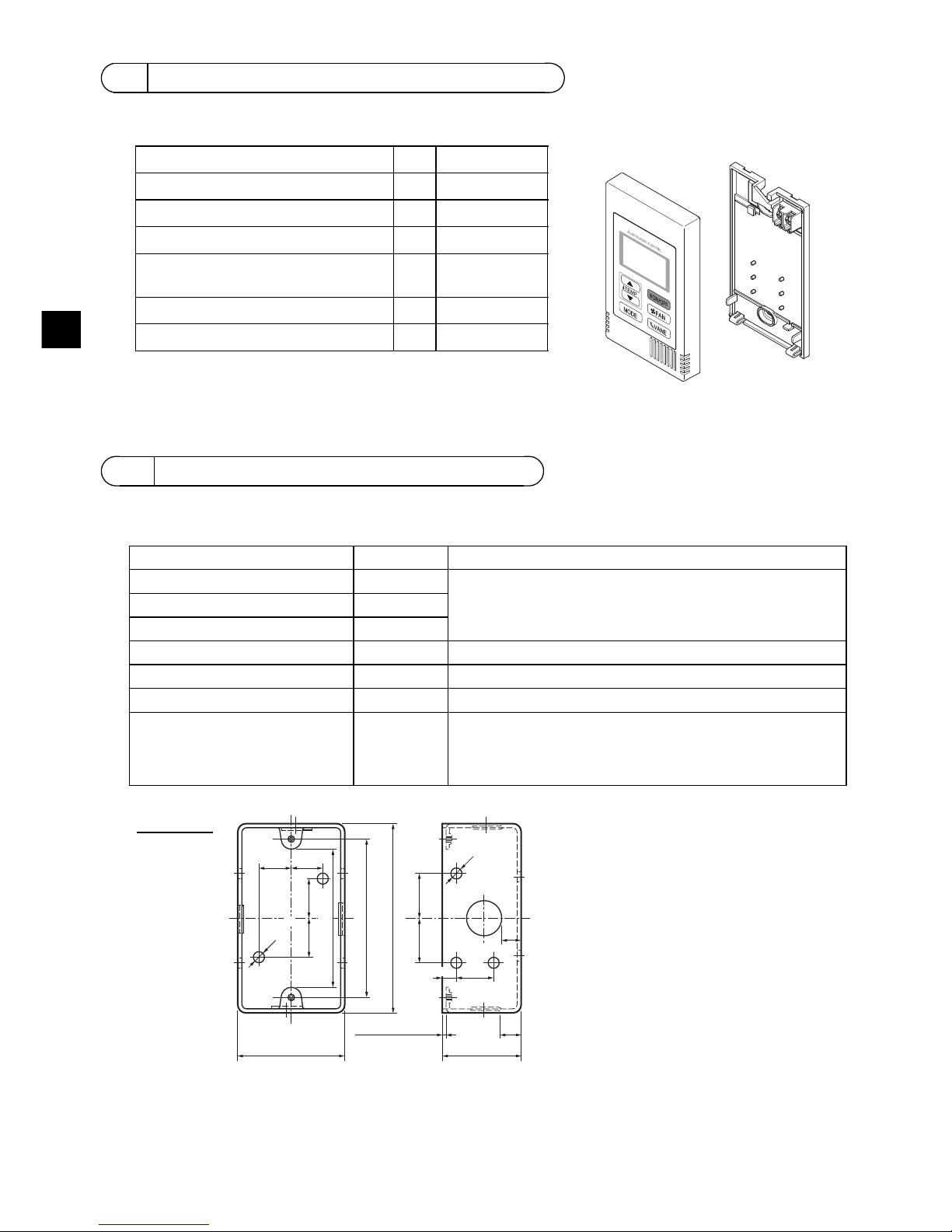
The following parts are included in the box.
(1) Field-supplied parts
The following parts are field-supplied parts.
(2) Field-supplied tools
• Flat-tip screwdriver (Width: 3 - 5 mm (1/8 - 7/32 inch))
• Knife or Nipper
• Miscellaneous tools
2 Component names and supplied parts
*3 ISO metric screw thread
*4 Remote controller cable is not included.
3 Field-supplied parts/Required tools
Parts name Qty. Notes
Single switch box 1 Not required for direct wall installation
Thin metal conduit Necessary
Lock nut and bushing Necessary
Cable cover Necessary Required for routing remote controller cable along a wall
Putty Reasonable
Molly anchor Necessary
Remote controller cable
(Use a 0.3 mm² (AWG22) 2-core
sheathed cable.)
Necessary If you need to use a cable extension longer than 10 m (32 ft),
select an electric wire that meets the following specifications:
Wire specification VCTF or CVV (2-core):
1.25 mm² (stranded 16 AWG) or equivalent
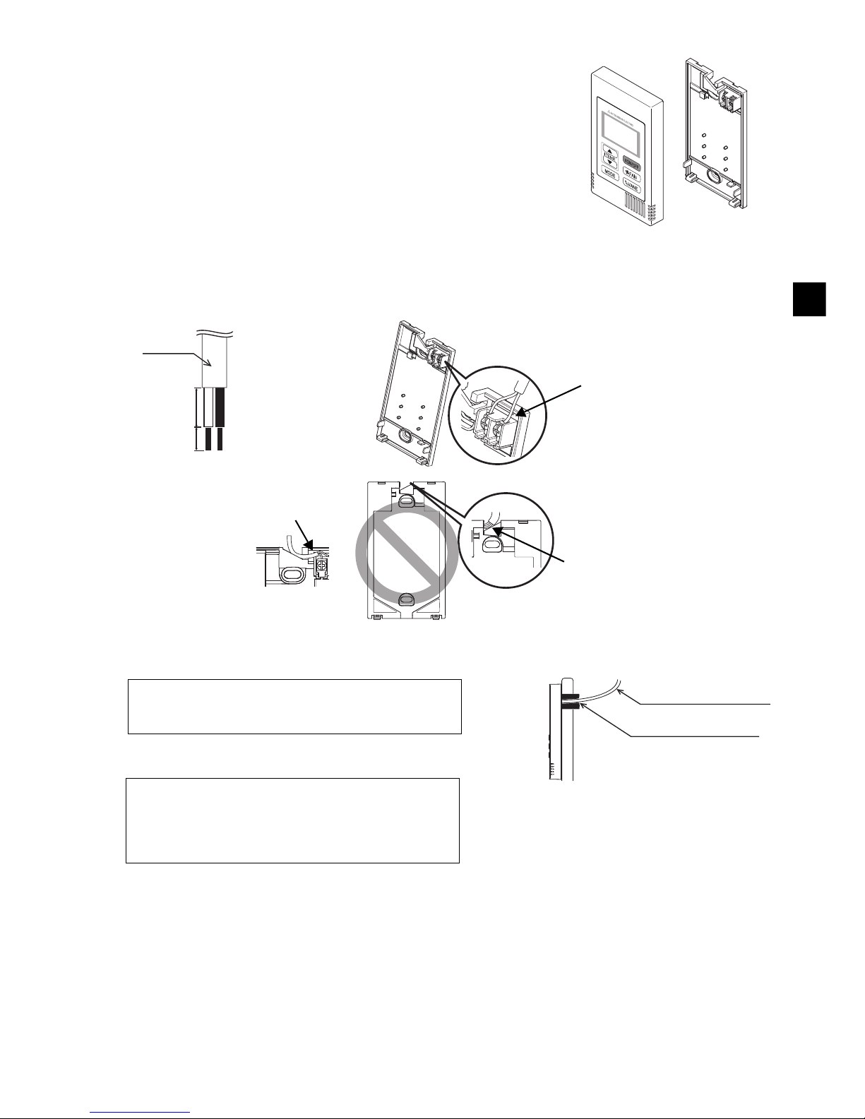
Parts name Qty. Appearance
Remote controller (top case) 1 Right figure *1
Remote controller (bottom case) 1 Right figure *2
Roundhead cross slot screws M4×30 2 *3
Wood screw 4.1×16
(for direct wall installation)
2*3
Installation Manual (this manual) 1
Instruction Book 1
Bottom case *2
Top case *1
h
16 (5/8) 16 (5/8)
25 (1)
25 (1)
102 (4)
54 (2-1/8)
20
(13/16)
10
(3/8)
44 (1-3/4)
1.5 (1/16) or less
83.5±0.4 (3-3/8±1/32)
ø6 (1/4OD)
20 (13/16)
6
(1/4)
ø6 (1/4OD)
20 (13/16)
Switch box
unit: mm (in)
Page 5
– 5 –
GB
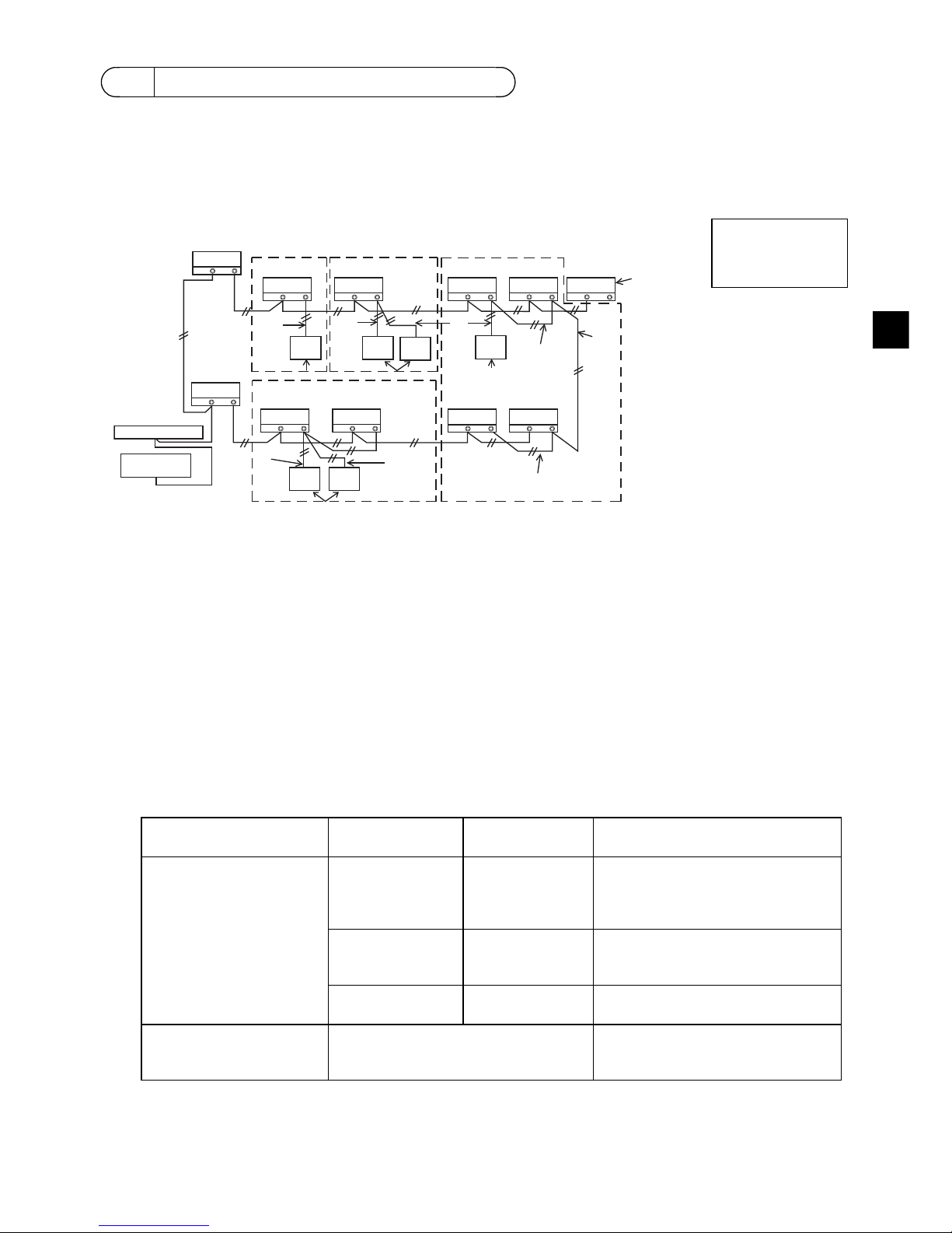
The wiring is different when the remote controller is connected to a CITY MULTI control system (“-A”
type and later) and when it is connected to a M-Series and P-Series air conditioner (A control type).
The wiring also differs with the system configuration. Check the system used.
1. Connecting to CITY MULTI control system
The numbers (1) to (4) in the figure correspond to items (1) to (4) in the following description.
(1) Wiring from the remote controller
• Connect to the MA remote controller terminal block (TB15) on the indoor unit.
• The terminal block has no polarity. Connect to the terminal block at the rear bottom of the remote
controller.
(2) Operating in a group (Groups 03, and 04 above)
• Interconnect the MA remote controller terminal block (TB15) of the indoor units you want to
operate as a group, and connect the MA remote controller to that point.
• When the remote controller is used in combination with the system controller as shown in the
figure above, group setting at the system controller (central controller in the figure above) is
necessary.
(3) Number of connectable remote controllers (groups 02 and 04)
• A main remote controller and one sub remote controller, a total of two, can be connected to a
group made up of indoor units.
NOTE: When using this Simple MA remote controller in combination with other MA remote
controllers, be sure to follow the compatibility rules below.
4 How To Wire Transmission Line
Connect to TB15
on the indoor unit.
a Outdoor unit
b Indoor unit
c LOSSNAY or
OA processing unit
d Main Remote Controller
e Sub Remote Controller
f Central controller
g Power supply unit for
transmission line
Indoor unit function Main remote
controller
Sub remote
controller
Compatibility
Models applicable for
AUTO (dual set point) and
SETBACK mode
This Simple MA
remote controller
This Simple MA
remote controller
Compatible, and AUTO (dual set
point) and SETBACK mode can be
used depending on the indoor units
to be connected.
Other MA remote
controllers
This Simple MA
remote controller
Compatible, but AUTO (dual set
point) and SETBACK mode cannot
be used.
This Simple MA
remote controller
Other MA remote
controllers
Incompatible
Models not applicable for
AUTO (dual set point) and
SETBACK mode
Combination with all of the above Compatible
TB5 TB15
TB5 TB15
bb
TB5 TB15
c
TB5 TB15
b
TB5 TB15
b
TB5 TB15
b
TB5 TB15
b
TB7 TB3
TB5 TB15
TB5 TB15
TB7 TB3
(1)
(1)
(3)
(3)
(1)
(3)
(3)
(2)
(2)
(2)
(4)
(1)
(1)
a
a
dde d
ed
bb
g
f
Address = 51
Address = 01 Address = 02
Address = 55
Address = 08
Address = 07
Address = 03
Address = 04 Address = 09
Address = 06
Address = 05
Group 01 Group 02 Group 03
Group 04
Page 6
– 6 –
GB
(4) To interlock to a LOSSNAY or OA processing unit, make the following settings using the remote
controller. (For a description of how to set an interlock, see section .)
Set the LOSSNAY or OA processing unit address and the address of all the indoor units you want
to interlock.
(5) Total length of remote controller wiring
• The simple MA controller can be wired up to 200 m (656 ft). Procure 0.75 - 1.25 mm
² (stranded 16
- 28 AWG), 2-core cable at the installation site.
2. Connecting to M-Series and P-Series air conditioner
The remote controller wiring depends on the system configuration. Check the system configuration.
Wire the remote controller as shown in the example below.
The numbers (1) to (3) in the figure correspond to items (1) to (3) in the following description.
[1] Connecting the remote controller for each refrigerant system (Standard 1:1, simultaneous twin,
simultaneous triple, simultaneous four, individual twin)
[2] When grouping by different refrigerant systems
* Set the refrigerant address using the outdoor unit dip switches. (For more information, refer to the
outdoor unit installation manual.)
* All the indoor units enclosed in are controlled as one group.
(1) Wiring from remote controller
• Connect to indoor unit TB5 (remote controller terminal block). (The terminal block has no polarity.)
• For simultaneous multi type, when mixing various types of indoor units, always connect the
remote controller to the indoor unit with the most functions (wind velocity, vane, louver, etc.).
(2) When grouping with difference refrigerant systems
• Group using the remote controller wiring. Connect the remote controller to an arbitrary indoor unit
of each refrigerant system you want to group.
• When mixing different types of indoor units in the same group, always make the outdoor unit
connecting the indoor unit with the most functions (wind velocity, vane, louver, etc.) the Main unit
(refrigerant address = 00). Also, when the Main unit is the simultaneous multi type, always satisfy
the conditions of (1) above.
• The Simple MA Remote Controller can control up to 16 refrigerant systems as one group.
CAUTION
Remote controllers cannot be wired together. Only one wire
can be connected to the remote controller terminal block.
Connect to TB5
on the indoor unit.
a Outdoor unit
b Indoor unit
d Main Remote Controller
(Simple MA Controller)
e Sub Remote Controller
(Simple MA Controller)
7
Ventilation Setting
ed
NOTE: When interlocking the MA remote controller with a LOSSNAY or OA processing unit,
always set the address of all the indoor units in the group and the address of the
LOSSNAY or OA processing unit.
(1)
(3)
TB5
TB4
TB1
TB4
(3)
(3)
(1)
TB4
TB4
TB5
TB1
TB4
TB5
TB1
TB1
TB4
TB5
(1)
(1)
(3)
(3)
(3)
a
bb
d
a
bb
de
a
bb
dde
Refrigerant
address = 00
Refrigerant
address = 00
Refrigerant
address = 00
Refrigerant
address = 00
Simultaneous twin Simultaneous twin Individual twin
TB4
TB4
TB4
TB4TB4
TB4
TB4TB4
TB1 TB1 TB1
TB1TB1
TB5
TB5
TB5
TB5
TB5
(2)
(1)
(3)
(3)
(1)
(2) (2)
(2)
aa a a
bbbbbbbb
de
Standard 1:1 Simultaneous twin
Simultaneous triple
Individual twin
Refrigerant
address = 01
(Sub)
Refrigerant
address = 03
(Sub)
Refrigerant
address = 04
(Sub)
Refrigerant
address = 00
(Main)
Refrigerant
address = 02
(Sub)
Page 7
– 7 –
GB
(3) Up to two remote controllers can be connected to one group
• When two remote controllers are connected to one group, always set the Main remote controller
and Sub remote controller.
• When only one remote controller is connected to one group, set it as the Main controller. When
two remote controllers are connected to one group, set the Main remote controller and Sub
remote controller. (For a description of how to set the Main/Sub switch, see step 5 in section
.)
NOTE: When using this Simple MA remote controller in combination with other MA remote
controllers, be sure to follow the compatibility rules below.
(4) Total length of remote controller wiring
• The Simple MA Remote Controller can be wired up to 200 m (656-1/8 ft).
Procure 0.75 ~ 1.25 mm
² (16 ~ 28 AWG), 2-core cable at the installation site.
This remote controller is for the wall installation. It can be installed either in the switch box or directly
on the wall. When performing direct wall installation, wires can be thread through either back or top of
the remote controller.
(1) Selecting an installation site
Install the remote controller (switch box) on the site where the following conditions are met.
(a) A flat surface
(b) A place where the remote controller can measure the accurate indoor temperature
Sensors to monitor indoor temperature are on the indoor unit and on the remote controller. When
the room temperature is monitored with the sensor on the remote controller, the built-in sensor on
the Main remote controller monitors the room temperature. When using the sensor on the remote
controller, follow the instructions below.
Indoor unit function Main remote
controller
Sub remote
controller
Compatibility
Models applicable for
AUTO (dual set point) and
SETBACK mode
This Simple MA
remote controller
This Simple MA
remote controller
Compatible, and AUTO (dual set
point) and SETBACK mode can be
used depending on the indoor units
to be connected.
Other MA remote
controllers
This Simple MA
remote controller
Compatible, but AUTO (dual set
point) and SETBACK mode cannot
be used.
This Simple MA
remote controller
Other MA remote
controllers
Incompatible
Models not applicable for
AUTO (dual set point) and
SETBACK mode
Combination with all of the above Compatible
CAUTION - The wiring cannot be connected to TB5 of the indoor unit of the same
refrigerant system. If so connected, the system will not operate normally.
- Remote controllers cannot be wired together. Only one wire can be connected
to the remote controller terminal block.
- When connecting to TB5, connect up to two wires of the same size to one
terminal block.
a Outdoor unit
b Indoor unit
d Main Remote Controller
e Sub Remote Controller
5How To Install
5
How To Install
d
d
TB4
TB4
TB4
TB4
TB4
TB4
TB1
TB1 TB1
TB1
TB5
TB5
TB5
TB5 TB5 TB5
a
bbb bbb
de
aa a
Refrigerant
address = 00
Refrigerant
address = 00
Refrigerant
address = 01
Refrigerant
address = 00
Simultaneous twin Standard 1:1 Simultaneous twin Standard 1:1
Page 8
– 8 –
GB
• To monitor the accurate indoor temperature, install the remote controller away from direct
sunlight, heat sources, and the supply air outlet of the air conditioner.
• Install the remote controller in a location that allows the sensor to measure the representative
room temperature.
• Install the remote controller where no wires are routed around the temperature sensor on the
controller. (If wires are routed, the sensor cannot measure accurate indoor temperature.)
(2) Installation space
Leave a space around the remote controller as shown in the figure shown below, regardless of
whether the controller is installed in the switch box or directly on the wall. Removing the remote
controller will not be easy with insufficient space.
Also, leave an operating space in front of the remote controller.
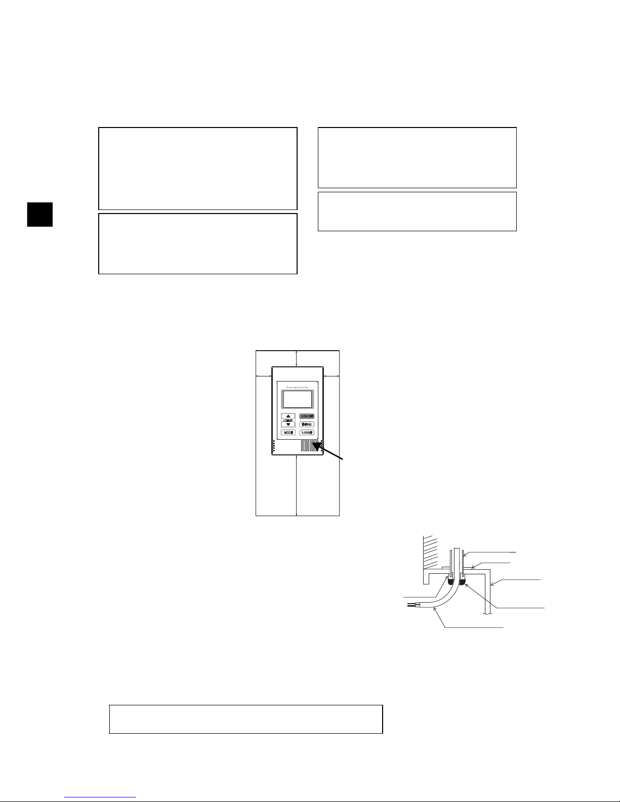
(3) Installation work
Controller can be installed either in the switch box or directly on the
wall. Perform the installation properly according to the installation
method.
1 Drill a hole in the wall.
■ Installation using a switch box
• Drill a hole in the wall, and install the switch box on the wall.
• Connect the switch box to the conduit tube.
■ Direct wall installation
• Drill a hole in the wall, and thread the cable through it.
2 Seal the cable access hole with putty
■ Installation using a switch box
• Seal the remote controller cable access hole at the
connection of switch box and conduit tube with putty.
Do not install the controller in a place where
the difference between the remote controller
surface temperature and the actual room
temperature will be great.
If the temperature difference is too high,
room temperature may not be adequately
controlled.
To reduce the risk of malfunctions, do not
install the controller in a place where water
or oil may come into contact with the
controller, or in a condensing or corrosive
environments.
To avoid deformation and malfunction, do
not install the remote controller in direct
sunlight or where the ambient temperature
may exceed 40ºC (104ºF) or drop below 0ºC
(32ºF).
Do not install the remote controller directly
onto electrically conductive objects such as
metal plate that has not been painted.
Important
.
30
(1-3/16)
30
(1-3/16)
30 (1-3/16)
120 (4-3/4)
Temperature sensor
unit: mm (in)
External dimensions of remote controller
Minimum required space
around the remote
controller
Wall
Conduit tube
Locknut
Switch box
Seal the gap
with putty.
Remote
controller cable
Bushing
To reduce the risk of electric shock, malfunctions, or fire, seal
the gap between the cables and cable access holes with putty.
Page 9
– 9 –
GB
3 Prepare the bottom case of the remote controller.
4 Connect the remote controller cable to the terminal block on the bottom case.
Peel off the remote controller cable sheath as shown below to connect to the terminal block properly.
Secure the remote controller cable so that the peeled part of the cable will fit into the case.
■ Direct wall installation
• Seal the hole through which the cable is threaded with putty.
Top case Bottom case
16 (21/32)
6 (1/4)
Sheath
Unit: mm (in)
Connect the cable.
(non-polarized)
2-core wire must not be
seen on the back.
Insert the sheathed part of the cable inside
the case, and then secure the cable.
Seal the gap with putty.
Route the cable behind
the remote controller.
Remote controller cable
To reduce the risk of electric shock, shorting, or
malfunctions, keep wire pieces and sheath shavings
out of the terminal block.
Do not use solderless terminals to connect cables to
the terminal block.
Solderless terminals may come in contact with the
circuit board and cause malfunctions or damage the
controller cover.
Important
Page 10
– 10 –
GB
5 Install the bottom case.
Be sure to secure two places of the bottom case.
6 Cut out the cable access hole.
■ Direct wall installation (when running the cable along the wall)
• Cut out the thin-wall part on the cover (the shaded area in the right
figure) with a knife or a nipper.
• Thread the cable from the groove behind the bottom case through
this access hole.
7 Set the dip switches on the top case.
When using two remote controllers in one group, set the dip switches.
When using two remote controllers in one group, specify the main and sub remote controllers using
dip switch No. 1 shown below.
• When connecting only one remote controller to one group, it is always the main remote controller.
When connecting two remote controllers to one group, set one remote controller as the main
remote controller and the other as the sub remote controller.
• The factory setting is “Main”.
There are switches on the back of the top case. Remote controller Main/Sub and other function
settings are performed using these switches. Ordinarily, only change the Main/Sub setting of SW1.
(The factory settings are ON for SW1, 3, and 4 and OFF for SW2.)
■ Installation using a switch box ■ Direct wall installation
Setting the dip switches
SW No. SW contents Main ON OFF Comment
1
Remote controller
Main/Sub setting
Main Sub
Set one of the two remote controllers at one
group to “ON”.
2
Temperature display
units setting
Celsius Fahrenheit
When the temperature is displayed in
[Fahrenheit], set to “OFF”.
3
Cooling/heating
display in AUTO mode
Yes No
When you do not want to display “Cooling” and
“Heating” in the AUTO mode, set to “OFF”.
4
Indoor temperature
display
Yes No
When you do not want to display the indoor
temperature, set to “OFF”.
Remote
controller
cable
Refer to 4.
Refer to 1.
Single switch box
Roundhead
cross slot
screws
Seal the cable
access hole
with putty.
Refer to 4.
Wood
screws
Remote
controller cable
To avoid deformation and damage to the
bottom case, do not overtighten the screws.
To avoid damage to the bottom case, do not
make holes on it.
Important
Page 11
– 11 –
GB
8 Connect the connector to the top case.
Connect the connector on the bottom case to the socket on the top case.
9 Insert the wires into the clamp.
0 Install the top case on the bottom case.
Two mounting tabs are at the top of the top case.
Hook those two tabs onto the bottom case, and click the top case into place. Check that the case is
securely installed and not lifted.
1 2 3 4
ON
OFF
Connect the
connector.
To prevent malfunctions, do not remove the
protective sheet or the circuit board from the
top case.
To prevent cable breakage and
malfunctions, do not hang the top controller
casing hang by the cable as shown in the
figure above.
Important
Clamp
Insert the wires.
Hold the wires in place with the clamp to
prevent undue force from being applied to
the terminal block and causing cable
breakage.
Important
Wall
Should not
be lifted.
When attaching the top casing to the bottom
casing, push it until it they click into place.
If they are not properly locked into place,
they may fall, causing personal injury,
controller damage, or malfunctions.
Important
Page 12

– 12 –
GB
■ Direct wall installation (when running the cable along the wall)
• Thread the cable through the access hole at the top of the remote controller.
• Seal the cut-out part of the cover with putty.
• Use a cable cover.
• Uninstalling the top case
1 Uninstalling the top case
Insert a flat-tip screwdriver with a blade width of 3-5 mm (1/8-7/32
inch) into the latches at the bottom of the remote controller and lift
the latches. Then, pull up the top case.
Seal the gap
with putty.
Use a cable
cover.
Thread the cable through the top of the
remote controller.
To prevent damage to the controller casing,
do not force the flat-tip screwdriver to turn
with its tip inserted in the slot.
Do not insert the flat-tip screwdriver too far.
Doing so will damage the circuit board.
Important
Page 13
– 13 –
GB
1. Before making a test run, refer to the “Test Run” section of the indoor unit installation manual.
2. When the [ON/OFF] button and [TEMP. ] button are pressed simultaneously for 2 seconds or
longer, test run is performed.
3. Stop the test run by pressing the [ON/OFF] button.
4. If trouble occurred during the test run, refer to the “Test Run” section of the indoor unit installation
manual.
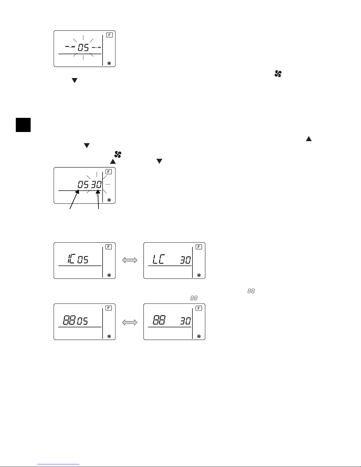
Perform this operation when you want to register the LOSSNAY or OA processing unit, confirm the
registered units, or delete the registered units controlled by the remote controller.
The following uses indoor unit address 05 and LOSSNAY or OA processing unit address 30 as an
example to describe the setting procedure.
[Setting Procedure]
1 Stop the air conditioner using the remote controller [ON/OFF] button.
2 Press and hold down the [ FAN] and [TEMP. ] buttons at the same time for two seconds. The
display shown below appears. The remote controller confirms the registered LOSSNAY or OA
processing unit addresses of the currently connected indoor units.
3 Registration confirmation result
- The indoor unit address and registered LOSSNAY or OA processing unit address are displayed
alternately.
6 Test Run
7 Ventilation Setting
COOL
VENTI.
Indoor unit piping temperature
Display range: -4ºF (-20ºC) to 158ºF (70ºC)
“-4ºF” or “158ºF” flashes on the display.
Test run time
The remaining time for test run is displayed.
Display range: 2:00 to 0:01
After two hours, the test run stops automatically.
Make this setting only when interlocked operation with LOSSNAY or OA processing unit is
necessary with CITY MULTI models.
(This setting cannot be made with M-Series and P-Series air conditioners.)
<Indoor unit address and indoor unit display>
<LOSSNAY address display and LOSSNAY display>
Page 14
– 14 –
GB
- When LOSSNAY or OA processing unit are not registered
4 If registration is unnecessary, end registration by pressing and holding down the [ FAN] and
[TEMP. ] buttons at the same time for two seconds.
If a new LOSSNAY or OA processing unit must be registered, go to step 1. Registration
procedure.
If you want to confirm another LOSSNAY or OA processing unit, go to step 2. Confirmation
procedure. To delete a registered LOSSNAY or OA processing unit, go to step 3. Deletion
procedure.
<1. Registration procedure>
5 Set the address of the indoor unit to be interlocked with the LOSSNAY unit using the [TEMP.
]
and [TEMP. ] buttons. (01 to 50)
6 After setting, press the [ FAN] button and set the Lossnay address you want to register by
operating the [TEMP. ] and [TEMP. ] buttons. (01~50)
7 Press the [ON/OFF] button, and register the set indoor unit address and LOSSNAY address.
- Registration end display
The indoor unit address and “IC” and LOSSNAY address and “LC” are alternately displayed.
- Registration error display
If the address is not registered correctly, the indoor unit address and [ ], and the registered
LOSSNAY (or OA processing unit address) and [ ] are alternately displayed.
Cannot be registered because the registered indoor unit or LOSSNAY or OA processing unit does
not exist.
Cannot be registered because another LOSSNAY or OA processing unit was registered at the
registered indoor unit.
Indoor unit address
LOSSNAY or OA processing unit address
Page 15
– 15 –
GB
<2. Confirmation procedure>
8 Set the address of the indoor unit connected by the remote controller whose LOSSNAY or OA
processing unit you want to confirm using the [TEMP. ] and [TEMP. ] buttons. (01 to 50)
9 Press the [ON/OFF] button and [ FAN] button simultaneously for 2 seconds, and check the
LOSSNAY address registered at the set indoor unit address.
- Confirmation end display (When LOSSNAY is connected.)
The indoor unit address and “IC” and registered LOSSNAY address and “LC” are alternately
displayed.
- Confirmation end display (When LOSSNAY or OA processing unit is not connected.)
- Registered indoor unit address does not exist.
<3. Deletion procedure>
Use this procedure when you want to delete registration of indoor units connected by the remote
controller and LOSSNAY or OA processing unit.
0 Confirm (see 2. Confirmation procedure) the LOSSNAY or OA processing unit you want to delete
and display the indoor units and LOSSNAY or OA processing unit confirmation results.
a Press the [TEMP. ] and [TEMP. ] buttons simultaneously for 2 seconds, and delete
registration of the LOSSNAY or OA processing unit address registered at the set indoor unit.
- Deletion end display
Indoor unit address and “– –” and registered LOSSNAY or OA processing unit address and “– –”
are alternately displayed.
- Deletion error display
When deletion was not performed properly.
Page 16

– 16 –
GB
Set the functions of each indoor unit from the remote controller, as required. The functions of each
indoor unit can be selected only from the remote controller.
Set the functions by selecting the necessary items from Table 1.
Table1. Function selection contents
(For a detailed description of the factory settings and mode of each indoor unit, refer to the indoor unit installation manual.)
* Static pressure setting can be made by using Mode 08 in combination with Mode 10 depending on
the indoor unit model. Refer to the Indoor unit Installation Manual for details.
* For mode numbers other than listed above, refer to the indoor unit installation manual.
8 Function Selection for M-Series and P-Series
Mode
No.
Mode Settings
Setting
No.
Check Unit numbers
01 Automatic recovery
after power failure
Disable 1 Set "00" for the Unit number.
These settings apply to all the
connected indoor units.
Enable (Four minutes of standby time is required
after the restoration of power.)
2
02 Thermistor selection
(Indoor temperature
detection)
Average temperature reading of the indoor units
in operation
1
Thermistor on the indoor unit to which the remote
controller is connected (fixed)
2
Built-in sensor on the remote controller 3
03 LOSSNAY connection Not connected 1
Connected (without outdoor air intake by the
indoor units )
2
Connected (with outdoor air intake by the indoor
units )
3
04 Power voltage 240 V 1
220 V, 230 V 2
05 AUTO mode Enable (Automatically the unit achieves effective
energy saving operation.)
1
Disable 2
07 Filter sign 100 hours 1 Set "01” to “04” or “AL” for the
Unit number.
These settings apply to each
indoor unit.
• If "01” (“02”, “03”, “04") is
set for the Unit number, the
settings apply only to the
specified indoor unit
regardless of the number of
connected indoor units (one
through four units).
• If "AL" is set for the Unit
number, the settings apply
to all the connected indoor
units regardless of the
number of connected
indoor units (one through
four units).
2500 hours 2
Not displayed 3
08 Fan speed Silent mode (or standard) 1
Standard (or High ceiling 1) 2
High ceiling (or High ceiling 2) 3
09 No. of air outlets 4 directional 1
3 directional 2
2 directional 3
10 Installed options No 1
(High performance filter)
Ye s 2
11 Vane setting No vanes (or the vane setting No.3 is effective.) 1
Equipped with vanes
(The vane setting No.1 is effective.)
2
Equipped with vanes
(The vane setting No.2 is effective.)
3
Make the following settings for M-Series and P-Series if necessary.
(This setting cannot be made with CITY MULTI Control System. To make CITY MULTI indoor
unit settings from the remote controller, refer to section .)
9 Function Selection for CITY MULTI
NOTE: When the indoor unit functions were changed using the function selection after
installation is complete, always indicate the set contents by entering check marks or
other marks in the appropriate check field of Table 1.
Page 17

– 17 –
GB
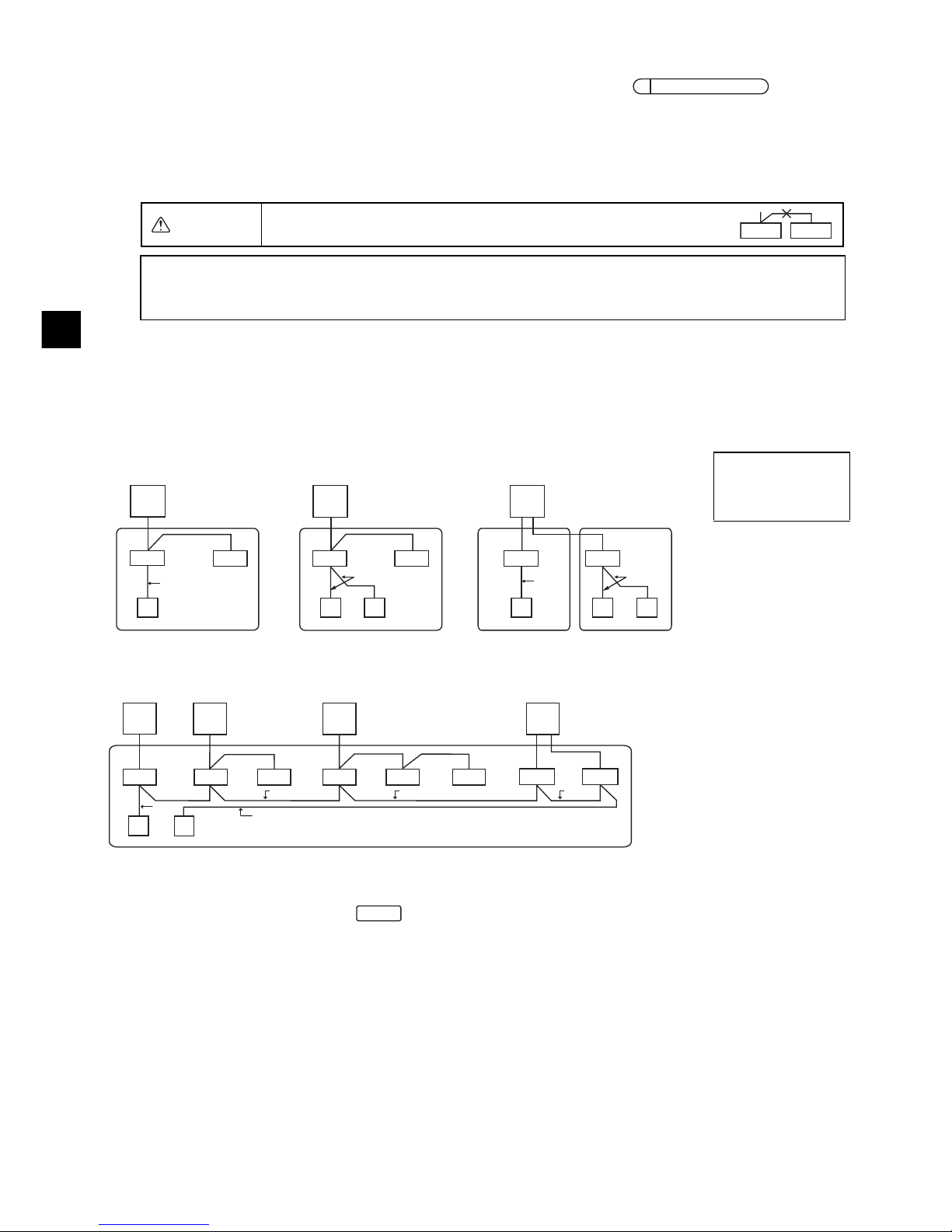
[Function selection flow]
First grasp the function selection flow. The following describes setting of “Thermistor selection” of
Table 1 as an example.
(For the actual setting procedure, see [Setting procedure] 1 to 0.)
[Setting procedure] (Set only when change is necessary.)
1 Check the set contents of each mode. When the set contents of a mode were changed by function
selection, the functions of that mode also change.
Check the set contents as described in steps 2 to 7 and change the setting based on the entries
in the Table 1 check field. For the factory settings, refer to the indoor unit installation manual.
-------------------------------------------------------------------------------------------------------------------------------------
2 Set the remote controller to Off.
Press and hold down the D [ FAN] and the C [TEMP. ] buttons at the same time for two
seconds or longer.
“ (FUNCTION)” blinks for a while, then the remote controller display changes to the display
shown below.
3 Set the outdoor unit refrigerant address No.
When the B [TEMP. ] and C [TEMP. ] buttons are pressed, the refrigerant address No.
decreases and increases between 00 and 15.
Set it to the refrigerant address No. whose function you want to select.
(This step is unnecessary for single refrigerant system.)
1 Check the function selection set contents.
2 Switch to the FUNCTION SELECTION mode.
(Press D and C simultaneously in the remote
controller OFF state.)
3 Refrigerant address specification
→ 00 (Outdoor unit specification)
(Unnecessary for single refrigerant system)
4 Unit address No. specification
(Buttons B, C and D)
→ 00 (Indoor unit specification)
5 Register (Press button A.)
6 Mode No. Selection
→ 02 (Thermistor selection)
7 Setting No. selection
(Buttons B, C and D)
→ 3 (Built-in sensor on the remote controller)
8 Register (Press button A.)
(Specified indoor unit
→ Fan operation)
End?
0 Ending function display
(Press buttons D and C simultaneously.)
9
Change
refrigerant
address and unit
address No.?
Ye s
No
Yes
No
.
A
D
C
B
Refrigerant address
display
Page 18

– 18 –
GB
* If the remote controller enters the OFF state after the “ (FUNCTION)” and room temperature
displays “ ” have flashes for two seconds, communication is probably abnormal. Make sure there
are no noise sources near the transmission line.
4 Set the indoor unit address No.
Press the D [ FAN] button. The unit address No. display “– –” flashes.
When the B [TEMP. ] and C [TEMP. ] buttons are pressed, the unit address No. changes in
the order of 00 ↔ 01 ↔ 02 ↔ 03 ↔ 04 ↔ AL. Set it to the unit address No. of the indoor unit whose
functions you want to set.
* When setting mode 1 ~ 6, set the unit address No. to “00”.
* When setting modes 7 to 14:
- When setting for each indoor unit, set the unit address No. to “01-04”.
- When batch setting for all indoor units, set the unit address No. to “AL”.
5 Refrigerant address and unit address No. registration
Press the A [ON/OFF] button. The refrigerant address and unit address No. are registered.
After a while, the mode No. display “– –” flashes.
* When “ ” flashes at the room temperature display, the selected refrigerant address is not in the
system. When “F” is displayed at the unit address No. display, and when it flashes together with
the refrigerant address display, the selected unit address No. does not exist. Correctly set the
refrigerant address and unit address No. by repeating steps 3 and 4.
When registered using the A [ON/OFF] , the registered indoor unit begins fan operation.
When you want to know the location of the indoor units of the unit address No. whose functions
were selected, check here.
When the unit address No. is 00 or AL, all the indoor units of the selected refrigerant address
perform the fan operation.
* When grouping by different refrigerant systems and an indoor unit other than the specified
refrigerant address performs the fan operation, the refrigerant address set here is probably
duplicated.
Recheck the refrigerant address at the outdoor unit dip switches.
NOTE: If you make a mistake during operation, end function selection by step 0 and repeat
selection from step 2.
Unit address No.
display
Mode No. display
EX): When refrigerant address 00, unit address No. = 02 registered
Refrigerant address 00
Indoor unit
Outdoor unit
Registration
Simple MA Controller
Fan operation
Unit address
No. 01
Unit address
No. 02
Unit address
No. 03
Page 19

– 19 –
GB
6 Mode No. selection
Select the mode No. you want to set with the B [TEMP. ] and C [TEMP. ] buttons. (Only the
settable mode numbers can be selected.)
7 Select the setting contents of the selected mode.
When the D [ FAN] button is pressed, the current setting No. flashes. Use this to check the
currently set contents.
Select the setting No. using the B [TEMP. ] and C [TEMP. ] buttons.
8 The contents set at steps 3 to 7 are registered.
When the A [ON/OFF] button is pressed, the mode No. and setting No. flash and registration
begins. The flashing mode No. and setting No. change to a steady light and setting ends.
* When “ ” flashes at the Mode No. display, communication is probably abnormal.
Make sure there are no noise sources near the transmission line.
-------------------------------------------------------------------------------------------------------------------------------------
9 To select more functions, press the D [ FAN] and repeat steps 3 to 8.
-------------------------------------------------------------------------------------------------------------------------------------
0 End function selection.
Press and hold down the C [TEMP. ] and D [ FAN] buttons at the same time for two seconds
or longer.
After a while, the function selection display disappears and the remote controller returns to the air
conditioner off display.
* Do not operate the air conditioner from the remote controller for 30 seconds after the end of
function selection.
Mode No. display
Mode No. 02 = Thermistor selection
Setting No. display
Setting No. 1 =
Average temperature
reading of the indoor
units in operation
Setting No. 3 =
Built-in sensor on the
remote controller
NOTE: When the functions of an indoor unit were changed by function selection after the end
of installation, always indicate the set contents by entering check marks or other marks
in the appropriate check field of Table 1.
Page 20

– 20 –
GB
Set the functions of each indoor unit from the remote controller, as required.
Refer to the Indoor unit Installation Manual for factory settings, mode No., and the setting No. of the
indoor units.
■ Setting the indoor unit Setting Value
4Press the [TEMP. ] and the [TEMP. ] buttons to set the address of the indoor unit whose
settings to be made. (0 to 50)
5Press the [MODE] button, then press the [TEMP. ] and the [TEMP. ] buttons to set the
Function Setting No. to be set. (000 to 255)
6Press the [MODE] button, then press the [TEMP. ] and the [TEMP. ] buttons to set the
Function Setting Value. to be set (00 to 15)
7Press the [ON/OFF] button to set the settings.
9 Function Selection for CITY MULTI
1 Press the [ON/OFF] button to stop the operation of the air conditioner.
2 Press and hold down the [MODE] and the [ FAN] buttons at the same time for two seconds
or longer to check the current settings.
3 When the response has been received from the indoor unit, the current settings appear. If
there is no response, nothing appears.
Make this setting only when the function settings need to be changed on CITY MULTI.
(This setting cannot be made with M-Series and P-Series Control System. To make settings
for M-Series and P-Series, refer to section .)
8
Function Selection for M-Series and P-Series
NOTE: Be sure to write down any settings that you change performing the following steps.
Air conditioner
stops.
Procedure A
2 sec.
[MODE]
+
[FAN]
Function Setting Value
Function Setting No.
Indoor unit address
Response is received.
Response has been received.
No response
No
response
Waiting for response
Page 21

– 21 –
GB
8If the set settings need to be changed, repeat steps 4 to 7.
To complete the settings, press the [MODE] and the [ FAN] buttons at the same time for two
seconds or longer.
■ Checking the indoor unit Function Setting Value
1Perform the Procedure A on the previous page.
2Press the [TEMP. ] and the [TEMP. ] buttons to set the address of the indoor unit whose
settings to be checked. (0 to 50)
3Press the [MODE] button, then press the [TEMP. ] and the [TEMP. ] buttons to set the
Function Setting No. to be checked. (000 to 255)
4Press the [ FAN] button to display the current Function Setting Value.
2 sec.
[MODE]
+
[FAN]
Response has been received.
[TEMP. ] [TEMP. ]
[MODE]
Indoor unit address setting Function Setting No. setting Function Setting Value setting
The setting for the specified
Function Setting No. has not been
completed.
Setting completed
The specified indoor unit does not
exist.
Waiting for response
Response has been received.
[MODE]
[ON/OFF]
No
response
Page 22

– 22 –
GB
5To check the settings, repeat steps 2 to 4.
To complete the checking process, press the [MODE] and the [ FAN] buttons at the same time
for two seconds or longer.
Retrieve the error history of each unit using the Simple MA controller.
1 Switch to the self-diagnosis mode.
When the A [ON/OFF] button and the C [TEMP. ] button are pressed for 5 seconds or longer,
the figure shown below is displayed.
2 Set the address or refrigerant address No. you want to self-diagnosis.
When the B [TEMP. ] and C [TEMP. ] are pressed, the address decreases and increases
between 01 and 50 or 00 and 15. Set it to the address No. or refrigerant address No. you want to
self-diagnosis.
-------------------------------------------------------------------------------------------------------------------------------------
10 Self diagnosis
Response has been received.
[TEMP. ] [TEMP. ]
Indoor unit address setting
Function Setting No. setting
[MODE]
[FAN]
Current
setting value
No
response
The setting for the specified Function Setting No. has not
been completed.
The specified indoor unit does not exist.
Waiting for response
Response has been received.
Response is
received.
Self-diagnosis address
or self-diagnosis
refrigerant address
Approximately three seconds
after the change operation, the
self-diagnosis refrigerant
address changes from flashing
to a steady light and selfdiagnosis begins.
Page 23

– 23 –
GB
3 Self-diagnosis result display <Error history> (For the contents of the error code, refer to the indoor
unit installation manual or service handbook.)
-------------------------------------------------------------------------------------------------------------------------------------
4 Error history reset
The error history is displayed in 3 self-diagnosis results display.
When the D [ FAN] button is pressed two times successively within three seconds, the selfdiagnosis object address and refrigerant address flash.
When the error history was reset, the display shown below appears.
When error history reset failed, the error contents are displayed again.
-------------------------------------------------------------------------------------------------------------------------------------
5 Self-diagnosis reset
There are the following two ways of resetting self-diagnosis.
Press the A [ON/OFF] button and the C [TEMP. ] button simultaneously for 5 seconds or
longer. → Resets self-diagnosis and returns to the state before self-diagnosis.
Press the A [ON/OFF] button. → Self-diagnosis resets and indoor units stop. (When operation is
prohibited, this operation is ineffective.)
1 First check the power mark.
When normal voltage (DC12V) is not applied to the remote
controller, the power mark goes off.
When the power mark is off, check the remote controller
wiring and the indoor unit.
2 Switch to the remote controller check mode.
When the B [TEMP. ] button and D [ FAN] button are pressed simultaneously for 5 seconds
or longer, the figure shown below is displayed.
When the A [ON/OFF] button is pressed, remote controller check begins.
-------------------------------------------------------------------------------------------------------------------------------------
11 Remote Controller Check
Error code 4 digits or
error code 2 digits
Error detection attribute
Address 3 digits or
unit address No. 2 digits
<When there is no error history> <When opposite side does not exist>
(Alternate
display)
When the air conditioner cannot be controlled from the Simple MA controller, use this function
to check the remote controller.
Power mark
Page 24

– 24 –
GB
3 Remote controller check result
<When remote controller is normal>
<When remote controller is faulty>
-------------------------------------------------------------------------------------------------------------------------------------
4 Remote controller check reset
When the B [TEMP. ] button and D [ FAN] button are pressed simultaneously for 5 seconds
or longer, remote controller diagnosis is reset and the [HO] and run lamp flash and 30 seconds later
the remote controller returns to its state before diagnosis.
Since there is no problem at the remote controller, check for other causes.
(Error display 1) “NG” flashes → Remote controller send/receive circuit abnormal
Remote controller switching is necessary.
When the problem is other than the checked remote controller
(Error display 2) “E3” “6833” “6832” flash → Cannot send
(Error display 3) “ERC” and data error count are displayed → Data error generation
There is noise on the transmission line, or the indoor unit or another remote controller is
faulty. Check the transmission line and the other remote controllers.
“Data error count” is the difference between the number of bits of remote controller send
data and the number of bits actually sent to the transmission line. In this case, the send
data was disturbed by the noise, etc. Check the transmission line.
When data error count is 02
Remote controller send data
Send data on transmission line
HEAD OFFICE: TOKYO BLDG., 2-7-3, MARUNOUCHI, CHIYODA-KU, TOKYO 100-8310, JAPAN
Page 25

– 1 –
F
Ce manuel d'installation décrit comment installer le contrôleur à distance simple MA en vue de son utilisation
avec le système de climatisation de bâtiment Mitsubishi, les unités intérieures de climatiseurs CITY MULTI de
type extension directe (type « -A » et ultérieurs), et les climatiseurs autonomes Mitsubishi des séries M et P.
Assurez-vous de lire ce manuel d'installation et le manuel d'instructions fourni avec le contrôleur à distance
avant de procéder à l'installation. Si les fichiers sont illisibles, veuillez contacter votre revendeur.
Pour des informations sur le câblage et l'installation des climatiseurs, reportez-vous au manuel d'installation.
Après l'installation, remettez ce manuel aux utilisateurs.
• Lisez les consignes de sécurité ci-après avant de procéder à l'installation.
• Respectez scrupuleusement ces consignes pour assurer la sécurité.
• Après avoir lu ce manuel, remettez-le à l'utilisateur final pour qu'il puisse le consulter en cas de
besoin.
• Conservez ce manuel pour pouvoir le consulter en cas de besoin. Ce manuel doit être fourni aux
personnes chargées de réparer ou de déplacer la télécommande. Assurez-vous que le manuel est
bien remis à tout futur utilisateur.
AVERTISSEMENT
1 Consignes de sécurité
AVERTISSEMENT
Signale un risque de blessure grave, voire mortelle en cas de
mauvaise utilisation du PAC-YT53CRAU.
ATTENTION
Signale un risque de blessure grave ou de dommage matériel en cas
de mauvaise utilisation du PAC-YT53CRAU.
Précautions générales
Seul un personnel qualifié est autorisé à réaliser les travaux électriques.
N'installez pas l'unité en un endroit où se trouvent de grandes
quantités d'huile, de vapeur, de solvants organiques ou de gaz
corrosifs tels du gaz sulfurique ou encore là où sont
fréquemment utilisés des aérosols ou des solutions acides/
alcalines. Ces substances peuvent affecter les performances
de l'unité ou provoquer la corrosion de certains de ses
composants, ce qui peut donner lieu à des défauts de
fonctionnement, des dégagements de fumée ou même une
électrocution ou un incendie.
Ne lavez pas la télécommande avec de l'eau ou tout autre
liquide afin de prévenir tout risque de court-circuit, de fuite
électrique, d'électrocution, de dysfonctionnement, de fumée
ou d'incendie.
N'utilisez par les commutateurs/touches ou d'autres parties
électriques avec les mains mouillées afin de prévenir tout
risque d'électrocution, de dysfonctionnement, de fumée ou
d'incendie.
Pour éviter tout risque de blessure ou d'électrocution,
éteignez la télécommande et coupez l'alimentation électrique
avant de la nettoyer, de l'examiner, ou avant toute opération
d'entretien de celle-ci.
Pour éviter tout risque de lésion ou d'électrocution, éteignez la
télécommande et couvrez-la avant de pulvériser un
quelconque produit chimique dans l'environnement de celuici.
Pour prévenir tout risque de blessure, tenez les enfants
éloignés pendant l'installation, l'inspection ou la réparation du
contrôleur.
Installez correctement toutes les protections requises pour
protéger la télécommande contre l'humidité et la poussière.
L'accumulation de poussière et d'eau peut provoquer des
électrocutions, de la fumée ou un incendie.
Système de contrôle CITY MULTI
et climatiseurs Mitsubishi séries M et P
Contrôleur à distance simple MA PAC-YT53CRAU
Manuel d’installation
WT06429X01
FR
Pour distribution aux distributeurs et aux sous-traitants
Page 26

– 2 –
F
ATTENTIO N
AVERTISSEMENT
ATTENTIO N
AVERTISSEMENT
ATTENTIO N
Précautions pendant l'installation
Précautions pendant le câblage
Pour prévenir tout risque d'endommager la télécommande, ne
pulvérisez pas d'insecticide ou tout autre aérosol inflammable
directement dessus.
Ne touchez pas l'écran tactile, les commutateurs ou les
touches avec un objet pointu ou tranchant afin de prévenir
tout risque d'électrocution ou de dysfonctionnement.
Évitez le contact avec les bords tranchants de certaines
parties afin de prévenir tout risque de blessure et
d'électrocution.
Pour prévenir tout risque de blessure, portez un équipement
de protection lors de toute intervention sur la télécommande.
Consultez votre revendeur pour en savoir plus sur la mise au
rebut appropriée du contrôleur.
N'installez pas le contrôleur dans un endroit où peut se
produire une fuite de gaz inflammable.
Si du gaz inflammable s'accumule autour de l'unité, il peut
s'enflammer et provoquer un incendie ou une explosion.
Pour prévenir tout risque de court-circuit, de fuite électrique,
d'électrocution, de dysfonctionnement, de fumée ou
d'incendie, n'installez pas le contrôleur en un endroit exposé à
l'eau ou à la condensation.
Le contrôleur doit être installé par du personnel qualifié
conformément aux instructions détaillées dans le Manuel
d'Installation. Une installation incorrecte peut être la cause
d'une électrocution ou d'un incendie.
Installez le boîtier supérieur dans le boîtier inférieur jusqu'à ce
qu'il s'enclenche.
Pour prévenir tout risque de dommage au contrôleur, de
dysfonctionnement, de dégagement de fumée ou d'incendie,
ne branchez pas le câble d'alimentation au bornier des
signaux.
Fixez correctement les câbles en place et laissez assez de
mou aux câbles pour ne pas exercer de contrainte sur les
bornes. Des câbles mal connectés peuvent se casser,
surchauffer, et provoquer de la fumée ou un incendie.
Pour prévenir tout risque de blessure et d'électrocution,
coupez l'alimentation générale avant d'effectuer un travail
électrique.
Tous les travaux électriques doivent être effectués par un
électricien qualifié conformément à la réglementation et aux
normes locales et en suivant les instructions décrites dans le
Manuel d'installation.
Pour réduire le risque d'électrocution, installez un disjoncteur
et un disjoncteur de courant résiduel sur l'alimentation.
Pour réduire le risque d'électrocution, de fumée ou d'incendie,
installez un disjoncteur par contrôleur.
Utilisez des disjoncteurs et des fusibles correctement calibrés
(disjoncteur, commutateur local <commutateur + fusible>,
disjoncteur sans fusible).
Le disjoncteur dont la capacité de disjonction est plus élevée
que la capacité spécifiée peut entraîner une électrocution, des
dysfonctionnements, de la fumée ou un incendie.
Pour prévenir tout risque de fuite électrique, de surchauffe, de
dégagement de fumée ou d'incendie, utilisez des câbles de
section appropriée pour le courant nominal spécifié.
Une mise à la terre appropriée doit être fournie par un
électricien agréé.
Ne connectez pas le fil de terre à une conduite de gaz ou
d'eau, un paratonnerre ou une ligne téléphonique.
Une mise à la terre inappropriée peut entraîner une
électrocution, de la fumée, un incendie ou un
dysfonctionnement résultant d'une interférence électrique.
Pour réduire les risques d'électrocution, de court-circuit ou de
dysfonctionnement, retirez toutes les chutes de fil et de gaine
du bornier.
Pour prévenir tout risque de court-circuit, de fuite électrique,
d'électrocution ou de dysfonctionnement, ne laissez pas les
câbles entrer en contact avec les bords vifs du contrôleur.
Pour prévenir tout risque d'électrocution, de
dysfonctionnement ou d'incendie, comblez l'espace entre les
câbles et les trous d'accès des câbles avec du mastic.
Page 27

– 3 –
F
AVERTISSEMENT
ATTENTIO NN
Précautions pour le déplacement ou la réparation la télécommande
Précautions supplémentaires
Seul un personnel qualifié doit être autorisé à réparer la
télécommande ou à la changer de place.
N'essayez pas de démonter ou de modifier vous-même la
télécommande.
Une installation ou une réparation non conforme peut
entraîner des blessures, une électrocution ou un incendie.
Pour réduire les risques d’électrocution, de court-circuit ou de
dysfonctionnement, retirez toutes les chutes de fil et de gaine
du bornier.
Pour prévenir tout dommage à l'unité, utilisez des outils
appropriés pour son installation, son inspection ou sa
réparation.
Ce contrôleur est exclusivement destiné à être utilisé avec le
Système de gestion d'immeuble de Mitsubishi Electric.
L'utilisation de ce contrôleur avec d'autres systèmes ou à
d'autres fins peut entraîner des dysfonctionnements.
N'utilisez pas de benzène, de diluant ou d'abrasif chimique
pour nettoyer le contrôleur, afin d'éviter de le décolorer.
Pour nettoyer le contrôleur, essuyez-le avec un chiffon doux
imbibé d'un mélange d'eau et d'un détergent doux, rincez les
restes de détergent avec un chiffon humide, puis essuyez
l'eau avec un chiffon sec.
Protégez le contrôleur contre l'électricité statique pour éviter
de l'endommager.
Prenez des dispositions appropriées contre les interférences
électromagnétiques lorsque les climatiseurs sont installés
dans des hôpitaux ou à proximité d'équipements de
radiocommunication.
Les onduleurs ainsi que les équipements médicaux à haute
fréquence ou de communication sans fil et les générateurs
d'énergie peuvent être la cause de dysfonctionnements du
système de climatisation. Le système de climatisation peut
également affecter le bon fonctionnement de ces types
d'équipement en créant du bruit électrique.
Pour prévenir tout dysfonctionnement, n'attachez pas les
câbles d'alimentation et de signaux ensemble et faites-les
passer dans des chemins de câbles différents.
Laissez la carte de circuit et son emballage protecteur sur le
boîtier.
Ne serrez pas trop les vis pour éviter d'endommager le
contrôleur.
Utilisez un tournevis à tête plate avec une lame de 5 mm
(7/32 pouce).
Ne tournez pas fermement le tournevis à tête plate dans le
loquet.
Pour prévenir toute déformation et dysfonctionnement,
n'installez par le contrôleur à distance en un endroit
directement exposé au soleil ou là où la température peut
dépasser 40 °C (104 °F) ou chuter au-dessous de 0 °C
(32 °F).
N'installez pas le contrôleur sur la porte du panneau de
commande.
Des vibrations ou des chocs subis par le contrôleur pourraient
l'endommager ou le faire tomber.
Fixez le câble avec un serre-fils.
N'utilisez pas de bornes à sertir pour raccorder les câbles au
bornier.
Ce type de borne risque d'entrer en contact avec le circuit
imprimé et de provoquer des dysfonctionnements, voire
même d'endommager le cache du contrôleur.
Une fois le connecteur branché, installez le boîtier supérieur
correctement.
Page 28

– 4 –
F
Les pièces suivantes sont incluses dans le coffret.
(1) Pièces à fournir sur le site
Les pièces suivantes sont des pièces à fournir sur le site.
(2) Outils à fournir sur site
• Tournevis à tête plate (Largeur : 3-5 mm (1/8-7/32 pouce))
• Couteau ou pince
• Outillage divers
2 Nomenclature des composants et pièces fournies
*3 Filet métrique ISO
*4 Le câble du contrôleur à distance n'est pas inclus.
3 Pièces à fournir sur le site/Outils nécessaires
Nomenclature Qté Remarques
Boîtier de connexion simple 1 Non nécessaire pour installation directe sur le mur
Conduit métallique à paroi mince Nécessaire
Écrou de blocage et presse-étoupe Nécessaire
Chemin de câble Nécessaire Nécessaire pour faire passer le câble du contrôleur à
distance le long d'un mur
Mastic Raisonnable
Boulon d'ancrage à gaine d'expansion Nécessaire
Câble du contrôleur à distance
(Utilisez un câble gainé à deux âmes
de 0,3 mm² (AWG22).)
Nécessaire Si vous devez utiliser une rallonge de plus de 10 m (32
ft), sélectionnez un câble électrique correspondant aux
spécifications suivantes :
Spécification du câble VCTF ou CVV (2 fils) :
1,25 mm² (torsadé 16 AWG) ou équivalent
Nomenclature Qté Apparence
Contrôleur à distance (
Boîtier supérieur
)1
Figure de droite
*1
Contrôleur à distance (
Boîtier inférieur
)1
Figure de droite
*2
Vis à tête ronde fente en croix M4×30 2 *3
Vis à bois 4,1×16
(pour montage direct sur le mur)
2*3
Manuel d’installation
(le présent document)
1
Manuel d'utilisation 1
Boîtier inférieur
*2
Boîtier supérieur
*1
h
16 (5/8) 16 (5/8)
25 (1)
25 (1)
102 (4)
54 (2-1/8)
20
(13/16)
10
(3/8)
44 (1-3/4)
83,5±0,4 (3-3/8±1/32)
ø6 (1/4OD)
20 (13/16)
6
(1/4)
ø6 (1/4OD)
20 (13/16)
1,5 (1/16) ou moins
Boîtier de connexion
Unité de mesure : mm (po)
Page 29

– 5 –
F
Le raccordement est différent lorsque le contrôleur à distance est connecté à un système de contrôle
CITY MULTI (de type « –A » et versions ultérieures) et lorsqu’il est connecté à un climatiseur des
séries M et P (de type de contrôle A).
Le raccordement dépend aussi de la configuration du système. Vérifiez le système utilisé.
1. Connectez le système de contrôle CITY MULTI
Les nombres (1) à (4) de l’illustration correspondent aux opérations (1) à (4) dans la description
suivante.
(1) Raccordement depuis le contrôleur à distance
• Connectez le câble au bloc de sorties du contrôleur à distance MA (TB15) situé sur l’appareil
intérieur.
• Le bloc de sorties n’a pas de polarité. Continuer jusqu’au bloc de sorties situé sur la partie
inférieure arrière du contrôleur à distance.
(2) Fonctionnement en groupe (Groupes 03 et 04 ci-dessus)
• Interconnectez le groupe de sorties (TB15) du contrôleur à distance MA des appareils intérieurs
que vous désirez combiner, et connectez le contrôleur à distance MA à cet endroit.
• Lorsque le contrôleur à distance est utilisé en association avec le contrôleur de système comme
illustré ci-dessus, il est nécessaire de régler le groupe sur le contrôleur du système (un contrôleur
central dans le schéma ci-dessus).
(3) Nombre de contrôleurs à distance pouvant être connectés (Groupes 02 et 04)
• Un contrôleur à distance principal et un contrôleur à distance secondaire, donc deux au total,
peuvent être connectés à un groupe d’appareils intérieurs.
REMARQUE : Lors de l'utilisation d'un contrôleur à distance simple MA avec d'autres contrôleurs
à distance MA, veillez à respecter les règles de compatibilité suivantes.
4 Comment brancher la ligne de transmission
Connectez le câble
au TB15 situé sur
l’appareil intérieur.
a Appareil extérieur
b Appareil intérieur
c Appareil LOSSNAY ou OA
d Contrôleur à distance
principale
e Contrôleur à distance
secondaire
f Contrôleur central
g Unité d’alimentation
électrique pour la ligne de
transmission
Fonction de l'unité intérieure Contrôleur à
distance principal
Contrôleur à
distance secondaire
Compatibilité
Modèles applicables pour
les modes AUTO (deux
points de réglage) et
INVERSION
Ce contrôleur à
distance simple
MA
Ce contrôleur à
distance simple MA
Compatibles. Les modes AUTO (deux
points de réglage) et INVERSION
peuvent être utilisés en fonction des
unités intérieures à connecter.
Autres contrôleurs
à distance MA
Ce contrôleur à
distance simple MA
Compatibles, mais les modes AUTO
(deux points de réglage) et
INVERSION ne sont pas utilisables.
Ce contrôleur à
distance simple
MA
Autres contrôleurs à
distance MA
Incompatibles
Modèles non applicables
pour les modes AUTO (deux
points de réglage) et
INVERSION
Combinaison de tous les contrôleurs à
distance ci-dessus
Compatibles
TB5 TB15
TB5 TB15
bb
TB5 TB15
c
TB5 TB15
b
TB5 TB15
b
TB5 TB15
b
TB5 TB15
b
TB7 TB3
TB5 TB15
TB5 TB15
TB7 TB3
(1)
(1)
(3)
(3)
(1)
(3)
(3)
(2)
(2)
(2)
(4)
(1)
(1)
a
a
dde d
ed
bb
g
f
Adresse = 51
Adresse = 01 Adresse = 02
Adresse = 55
Adresse = 08
Adresse = 07
Adresse = 03
Adresse = 04 Adresse = 09
Adresse = 06
Adresse = 05
Groupe 01 Groupe 02 Groupe 03
Groupe 04
Page 30

– 6 –
F
(4) Pour interverrouiller un appareil LOSSNAY ou OA, effectuez les réglages suivants en utilisant le
contrôleur à distance. (Pour l’interverrouillage, reportez-vous à la section .)
Réglez l’adresse de l’appareil LOSSNAY ou OA et celle de tous les autres appareils intérieurs
que vous voulez interverrouiller.
(5) Longueur maximum du câble du contrôleur à distance
• Le contrôleur à distance simple MA peut être installé à 200 m (656 ft) de l’appareil. Procurez-vous
des câbles à deux âmes de 0,75 à 1,25 mm
² (torsadé 16 à 28 AWG) pour l’installation.
2. Connexion à un climatiseur des séries M et P
Le raccordement du contrôleur à distance dépend de la configuration du système. Vérifiez cette
configuration et raccordez le contrôleur à distance comme indiqué dans l’exemple ci-dessous.
Les numéros (1) à (3) du schéma correspondent aux opérations (1) à (3) de la description suivante.
[1]
Connexion du contrôleur à distance pour chaque système réfrigérant (Standard 1:1, deux appareils
simultanés, trois appareils simultanés, quatre appareils simultanés, deux appareils individuels)
[2] Pour le groupement des appareils par système réfrigérant
* Réglez l’adresse du réfrigérant en utilisant les commutateurs dip de l’appareil extérieur (pour plus
d’informations, reportez-vous au manuel d’installation de l’appareil extérieur).
* Tous les appareils intérieurs repris entre sont contrôlés comme un seul groupe.
(1) Raccordement depuis le contrôleur à distance
• Connectez le câble au bloc de sorties du contrôleur à distance (TB5) situé sur l’appareil intérieur
(le bloc de sorties n’a pas de polarité).
• Pour les appareils de type multi simultané, si vous mélangez plusieurs types d’appareils
intérieurs, connectez toujours le contrôleur à distance à l’appareil intérieur qui possède le plus de
fonctions (vitesse de la soufflerie, pale, ailette, etc.).
(2) Pour le groupement avec différents systèmes réfrigérants
• Les groupes qui utilisent le raccordement par contrôleur à distance. Connectez le contrôleur à
distance à un appareil intérieur arbitraire pour chaque système réfrigérant que vous voulez
introduire dans le groupe.
• Si vous utilisez plusieurs types d’appareil intérieur dans un même groupe, considérez toujours la
connexion de l’appareil extérieur à l’appareil intérieur qui possède le plus de fonctions (vitesse de
soufflerie, pale, ailette, etc.) comme connexion principale (adresse du réfrigérant = 00). De
même, si l’appareil principal est de type multi simultané, respectez toujours les conditions
énumérées en (1) ci-dessus.
• Le contrôleur à distance simple MA peut contrôler jusqu’à 16 systèmes réfrigérants dans un seul groupe.
ATTENTION
Les contrôleurs à distance ne peuvent pas être raccordés
ensemble. Un seul câble peut être connecté au bloc de sorties
du contrôleur à distance.
Connectez le câble
au TB5 situé sur
l’appareil intérieur.
a Appareil extérieur
b Appareil intérieur
d Contrôleur à distance
principale
(
Contrôleur à distance
simple MA
)
e Contrôleur à distance
secondaire
(
Contrôleur à distance
simple MA
)
7 Réglage du ventilateur
ed
REMARQUE : Lors du verrouillage du contrôleur à distance MA avec l’appareil LOSSNAY ou OA, veuillez
toujours régler l’adresse de tous les appareils intérieurs du groupe et l’adresse de l’appareil
LOSSNAY ou OA.
(1)
(3)
TB5
TB4
TB1
TB4
(3)
(3)
(1)
TB4
TB4
TB5
TB1
TB4
TB5
TB1
TB1
TB4
TB5
(1)
(1)
(3)
(3)
(3)
a
bb
d
a
bb
de
a
bb
dde
Adresse du
réfrigérant = 00
Adresse du
réfrigérant = 00
Adresse du
réfrigérant = 00
Adresse du
réfrigérant = 00
Deux appareils simultanés Deux appareils simultanés Deux appareils individuels
TB4
TB4
TB4
TB4TB4
TB4
TB4TB4
TB1 TB1 TB1
TB1TB1
TB5
TB5
TB5
TB5
TB5
(2)
(1)
(3)
(3)
(1)
(2) (2)
(2)
aa a a
bbbbbbbb
de
Standard 1:1 Deux appareils simultanés
Trois appareils simultanés
Deux appareils individuels
Adresse du
réfrigérant = 01
(Secondaire)
Adresse du
réfrigérant = 03
(Secondaire)
Adresse du
réfrigérant = 04
(Secondaire)
Adresse du
réfrigérant = 00
(Principal)
Adresse du
réfrigérant = 02
(Secondaire)
Page 31

– 7 –
F
(3) Il est possible de connecter jusqu’à deux contrôleurs à distance à un seul groupe
• Lorsque deux contrôleurs à distance sont connectés à un seul groupe, définissez toujours un
contrôleur à distance principal et un contrôleur à distance secondaire.
• Lorsqu’il n’y a qu’un contrôleur à distance connecté à un groupe, réglez-le comme étant le
contrôleur à distance principal. Lorsque deux contrôleurs à distance sont connectés à un seul
groupe, définissez toujours un contrôleur à distance principal et un contrôleur à distance
secondaire (pour le réglage du commutateur principal/secondaire, reportez-vous à l’opération 5
dans la section .)
REMARQUE : Lors de l'utilisation d'un contrôleur à distance simple MA avec d'autres contrôleurs
à distance MA, veillez à respecter les règles de compatibilité suivantes.
(4) Longueur totale du câble du contrôleur à distance
• Le contrôleur à distance simple MA peut être installé à 200 m (656-1/8 ft) de l’unité.
Procurez-vous des câbles à 2 âmes, de 0,75 à 1,25 mm
² (16 à 28 AWG) de section.
Ce contrôleur à distance est prévu pour une installation murale. Il peut être installé dans le boîtier de
connexion ou directement sur le mur. Lorsque vous effectuez une installation directe sur un mur les
fils peuvent être passés par l'arrière ou sur le dessus du contrôleur à distance.
(1) Choix d'un site d'installation
Installez le contrôleur à distance (boîtier de connexion) sur le site dans un endroit satisfaisant aux
conditions suivantes.
(a) Une surface plane
(b) Un endroit où le contrôleur à distance peut mesurer la température interne exacte
Les capteurs de surveillance de la température intérieure sont situés sur l'unité intérieure et sur le
contrôleur à distance. Quand la température est surveillée avec le capteur du contrôleur à
distance, le capteur intégré au contrôleur à distance principal surveille la température de la pièce.
Lorsque vous utilisez le capteur du contrôleur à distance, suivez les instructions ci-dessous.
Fonction de l'unité intérieure Contrôleur à distance
principal
Contrôleur à
distance secondaire
Compatibilité
Modèles applicables pour les
modes AUTO (deux points de
réglage) et INVERSION
Ce contrôleur à
distance simple MA
Ce contrôleur à
distance simple MA
Compatibles. Les modes AUTO (deux
points de réglage) et INVERSION peuvent
être utilisés en fonction des unités
intérieures à connecter.
Autres contrôleurs à
distance MA
Ce contrôleur à
distance simple MA
Compatibles, mais les modes AUTO
(deux points de réglage) et INVERSION
ne sont pas utilisables.
Ce contrôleur à
distance simple MA
Autres contrôleurs à
distance MA
Incompatibles
Modèles non applicables pour
les modes AUTO (deux points
de réglage) et INVERSION
Combinaison de tous les contrôleurs à
distance ci-dessus
Compatibles
ATTENTIO N
- Le raccordement ne peut pas se faire sur le TB5 de l’appareil intérieur d’un même
système réfrigérant, sinon le système ne fonctionnera pas correctement.
- Les contrôleurs à distance ne peuvent pas être raccordés ensemble. Un seul câble
peut être connecté au bloc de sorties d’un contrôleur à distance.
- Si vous connectez le câble au TB5, vous pouvez connecter jusqu’à deux câbles de
même dimension sur un seul bloc de sorties.
a Appareil extérieur
b Appareil intérieur
d Contrôleur à distance
principal
e Contrôleur à distance
secondaire
5 Installation
5 Installation
d
d
TB4
TB4
TB4
TB4
TB4
TB4
TB1
TB1 TB1
TB1
TB5
TB5
TB5
TB5 TB5 TB5
a
bbb bbb
de
aa a
Adresse du
réfrigérant = 00
Adresse du
réfrigérant = 00
Adresse du
réfrigérant = 01
Adresse du
réfrigérant = 00
Deux appareils simultanés
Standard 1:1
Deux appareils simultanés
Standard 1:1
Page 32

– 8 –
F
• Pour surveiller la température intérieure exacte, installez le contrôleur à distance à l'écart de la
lumière directe du soleil, des sources de chaleur, et de la sortie d'air du climatiseur.
• Installez le contrôleur à distance dans un endroit qui permette au capteur de mesurer une
température représentative de celle de la pièce.
• Installez le contrôleur à distance à un endroit ou aucun fil ne passe à proximité du capteur de
température du contrôleur. (Si des fils passent à proximité, le capteur ne peut pas mesurer
exactement la température intérieure.)
(2) Espace d'installation
Que le contrôleur à distance soit installé dans le boîtier de connexion ou directement sur le mur,
laissez un espace autour du contrôleur comme indiqué sur la figure ci-dessous. Il ne sera pas facile
d'enlever le contrôleur si l'espace est insuffisant.
Laissez également un espace adéquat devant le contrôleur à distance pour faciliter son utilisation.
(3) Travaux d'installation
Le contrôleur peut être installé dans le boîtier de connexion ou
directement sur le mur. Effectuez l'installation adéquatement selon
la méthode d'installation.
1 Percez un trou dans le mur.
■ Installation avec un boîtier de connexion
• Percez un trou dans le mur, et installez le boîtier de
connexion sur le mur.
• Raccordez le boîtier de connexion au conduit.
■ Installation directe sur le mur
• Percez un trou dans le mur, et passez le câble à travers le
trou.
2 Bouchez le trou d'accès du câble avec du mastic
■ Installation avec un boîtier de connexion
• Bouchez le trou d'accès du câble du contrôleur à distance, à la jointure entre le boîtier de
connexion et le conduit, avec du mastic.
N'installez pas le contrôleur dans un endroit où
la différence entre la température de la surface
du contrôleur à distance et la température
effective de la pièce est importante.
Si la différence de température est trop élevée,
la température de la pièce peut ne pas être
contrôlée correctement.
Pour réduire le risque de dysfonctionnement,
n'installez pas le contrôleur où il pourrait entrer
en contact avec de l'eau ou de l'huile ou dans
des environnements corrosifs ou sujets à la
condensation.
Pour prévenir toute déformation et
dysfonctionnement, n'installez par le contrôleur
à distance en un endroit directement exposé au
soleil ou là où la température peut dépasser
40 °C (104 °F) ou chuter au-dessous de 0 °C
(32 °F).
N'installez pas le contrôleur à distance
directement sur des objets conducteurs comme
une plaque métallique non peinte.
Important
.
30
(1-3/16)
30
(1-3/16)
30 (1-3/16)
120 (4-3/4)
Capteur de température
Unité de mesure : mm (po)
Dimensions externes du
contrôleur à distance
Espace minimum requis autour du
contrôleur à distance
Mur
Tube conduit
Écrou de blocage
Boîtier de
connexion
Scellez l'interstice
avec du mastic.
Câble du
contrôleur à distance
Presseétoupe
Pour prévenir tout risque d'électrocution, de dysfonctionnement ou d'incendie,
comblez l'espace entre les câbles et les trous d'accès des câbles avec du mastic.
Page 33

– 9 –
F
3 Préparez le boîtier inférieur du contrôleur à distance.
4 Connectez le câble du contrôleur à distance au bornier sur le boîtier inférieur.
Dénudez la gaine du câble du contrôleur à distance comme illustré ci-après pour connecter
correctement le bloc terminal.
Fixez le câble du contrôleur à distance de sorte que la partie dénudée du câble se trouve dans le
boîtier.
■ Installation directe sur le mur
•
Bouchez le trou par lequel le câble a été passé avec du mastic.
Boîtier supérieur Boîtier inférieur
16 (21/32)
6 (1/4)
Gaine
Unité de mesure : mm (po)
Connectez le câble.
(non polarisé)
Le fil à deux conducteurs
ne doit pas être visible sur
l'arrière.
Insérez la partie dénudée du câble dans
le boîtier, puis fixez le câble.
Bouchez l'espace avec
du mastic.
Faites passer le câble derrière
le contrôleur à distance.
Câble du contrôleur à
distance
Pour réduire les risques d’électrocution, de courtcircuit ou de dysfonctionnement, retirez toutes les
chutes de fil et de gaine du bornier.
N'utilisez pas de bornes à sertir pour raccorder les
câbles au bornier.
Ce type de borne risque d'entrer en contact avec le
circuit imprimé et de provoquer des
dysfonctionnements, voire même d'endommager le
cache du contrôleur.
Important
Page 34

– 10 –
F
5 Installez le boîtier inférieur.
Veillez à fixer le boîtier inférieur en deux endroits.
6 Découpez le trou d'accès du câble.
■ Installation directe sur le mur (
quand on fait passer le câble le long du mur
)
• Découpez la partie peu épaisse sur le boîtier (indiquée par la zone
hachurée sur la figure de droite) avec un couteau ou une pince.
• Faites passer le câble de la rainure à l'arrière du boîtier inférieur à
travers ce trou d'accès.
7 Réglez les commutateurs DIP sur le boîtier supérieur.
Si vous utilisez deux contrôleurs à distance pour un seul groupe, réglez les commutateurs DIP.
Si vous utilisez deux contrôleurs à distance pour un seul groupe, choisissez le contrôleur à distance
principal et le contrôleur à distance secondaire en utilisant le commutateur DIP N° 1 comme indiqué
ci-dessous.
• Si vous ne connectez qu'un seul contrôleur à distance sur un groupe, il s’agit toujours du
contrôleur à distance principal. Si vous connectez deux contrôleurs à distance sur un seul groupe,
choisissez le principal, l’autre sera le contrôleur à distance secondaire.
• Le réglage d’usine est “Principal”.
Des commutateurs sont également présents à l'arrière du boîtier supérieur. Les réglages de la
fonction contrôleur à distance Principal/Secondaire et des autres fonctions se font en utilisant ces
commutateurs. D’ordinaire, il ne faut changer que le réglage Principal/Secondaire du commutateur
SW1. (Les réglages usine sont ON pour SW1, 3 et 4 et OFF pour SW2.)
■ Installation avec un boîtier de connexion ■ Installation directe sur le mur
Réglage des commutateurs DIP
N° du SW SW mis en principale ON OFF Commentaires
1
Réglage Principal/
Secondaire du contrôleur à
distance
Principal Secondaire
Réglez un des deux contrôleurs à distance
du groupe sur « ON ».
2
Réglage des affichages de
température
Celsius Fahrenheit
Lorsque la température est affichée en
[Fahrenheit], réglez sur « OFF ».
3
Affichage Refroidissement/
chauffage en mode
automatique
Oui Non
Si vous ne voulez pas que “Cooling”
(refroidissement) ou “Heating” (chauffage)
s’affiche en mode automatique, réglez sur
« OFF ».
4
Affichage de la température
intérieure
Oui Non
Lorsque vous ne voulez pas afficher la
température intérieure, sélectionnez
« OFF ».
Câble du
contrôleur
à distance
Reportez-vous à 4.
Reportez-vous à 1.
Boîtier de
connexion simple
Vis à tête
ronde à fente
en croix
Bouchez le trou
d'accès du câble
avec du mastic.
Reportez-vous à 4.
Vis à bois
Câble du
contrôleur à
distance
Ne serrez pas trop les vis pour éviter
d'endommager le boîtier inférieur.
Ne percez pas de trous dans le boîtier
inférieur pour ne pas l'endommager.
Important
Page 35

– 11 –
F
8 Reliez le connecteur au boîtier supérieur.
Reliez le connecteur du boîtier inférieur à la prise du boîtier supérieur.
9 Insérez les câbles dans le serre-fils.
0 Installez le boîtier supérieur sur le boîtier inférieur.
Le dessus du boîtier supérieur comporte deux pattes de montage.
Accrochez ces pattes sur le boîtier inférieur, et encliquetez pour mettre le boîtier supérieur en place.
Vérifiez que le boîtier est installé solidement et n'est pas décollé du fond.
1 2 3 4
ON
OFF
Reliez le
connecteur.
Pour éviter des dysfonctionnements, ne
retirez pas le film de protection ou le circuit
imprimé du boîtier supérieur.
Pour éviter une rupture du câble et des
dysfonctionnements, ne laissez pas le
boîtier supérieur du contrôleur pendre au
bout du câble comme illustré ci-dessus.
Important
Serre-fils
Insérez les
câbles.
Maintenez les câbles en place avec le serrefils pour éviter d'appliquer une force
excessive au bloc terminal et casser le
câble.
Important
Mur
Ne pas
soulever.
Quand vous fixez le couvercle et le boîtier
supérieur au boîtier inférieur, poussez-les
jusqu'à ce qu'ils s'enclenchent en place.
S'ils ne sont pas correctement verrouillés en
place, ils peuvent tomber, et provoquer des
blessures, des dommages au contrôleur, ou
des dysfonctionnements.
Important
Page 36

– 12 –
F
■ Installation directe sur le mur (quand on fait passer le câble le long du mur)
• Enfilez le câble dans le trou d'accès en haut du contrôleur à distance.
• Bouchez la partie évidée du couvercle avec du mastic.
• Utilisez un chemin de câble.
• Désinstallation du boîtier supérieur
1 Désinstallation du boîtier supérieur
Insérez un tournevis à tête plate d'une largeur de 3-5 mm
(1/8-7/32 pouce) dans les loquets en bas du contrôleur à distance
et soulevez les loquets. Retirez le boîtier supérieur.
Bouchez l'espace
avec du mastic.
Utilisez un chemin
de câble.
Enfilez le câble à travers le dessus du
contrôleur à distance.
Pour éviter d'endommager le boîtier du
contrôleur, ne tournez pas le tournevis à tête
plate la pointe insérée dans l'encoche de
force.
N'insérez pas le tournevis à tête plate trop
loin. Ceci pourrait endommager la carte de
circuit.
Important
Page 37

– 13 –
F
1. Avant d’effectuer un essai de fonctionnement, reportez-vous à la section “Essai de
fonctionnement” du manuel d’installation de l’appareil intérieur.
2. Lorsque vous appuyez simultanément sur les boutons [ON/OFF] et [TEMP. ] pendant deux
secondes ou plus, l’appareil effectue un essai de fonctionnement.
3. Arrêtez l’essai de fonctionnement en appuyant sur le bouton [ON/OFF].
4. Si un problème survient pendant l’essai de fonctionnement, reportez-vous à la section “Essai de
fonctionnement” du manuel d’installation de l’appareil intérieur.
Effectuez cette opération lorsque vous souhaitez enregistrer l’appareil LOSSNAY ou OA, confirmer
les appareils enregistrés ou supprimer le nom des appareils enregistrés contrôlés par le contrôleur à
distance.
L’exemple suivant utilise l’adresse 05 de l’appareil intérieur et l’adresse 30 de l’appareil LOSSNAY ou
OA pour décrire la procédure de réglage.
[Procédure de réglage]
1 Arrêtez le climatiseur via le bouton [ON/OFF] du contrôleur à distance.
2 Appuyez simultanément sur les boutons [ FAN] et [TEMP. ] et maintenez-les enfoncés
pendant deux secondes. L’affichage ci-dessous apparaît. Le contrôleur à distance confirme les
adresses des appareils enregistrés LOSSNAY ou OA des appareils intérieurs actuellement
branchés.
3 Résultat de la vérification de l’enregistrement
- L’adresse de l’appareil intérieur et l’adresse de l’appareil LOSSNAY ou OA enregistré sont
affichés en alternance.
6 Essai de fonctionnement
7 Réglage du ventilateur
COOL
VENTI.
Température de la tuyauterie de l'unité intérieure
Plage d'affichage : -4ºF (-20ºC) à 158ºF (70ºC)
« -4ºF » ou « 158ºF » clignote à l'écran.
Durée de l'essai de fonctionnement
Le temps restant d'exécution de l'essai de fonctionnement s'affiche.
Plage d'affichage : 2:00 à 0:01
Après deux heures, le essai de fonctionnement s'arrête
automatiquement.
Effectuez ce réglage uniquement lorsqu’il est nécessaire d’interverrouiller l’appareil LOSSNAY
ou OA avec les modèles CITY MULTI.
(Vous ne pouvez pas effectuer ce réglage avec les climatiseurs des séries M et P.)
<Adresse de l’appareil intérieur et
affichage de l’appareil intérieur>
<Affichage de l’adresse LOSSNAY et
affichage de l’appareil LOSSNAY>
Page 38

– 14 –
F
- Lorsque l’appareil LOSSNAY ou OA n’est pas enregistré
4 Si l’enregistrement n’est pas nécessaire, terminez l’enregistrement en appuyant simultanément sur
les boutons [ FAN] et [TEMP. ] et maintenez-les enfoncés pendant deux secondes.
Si vous devez enregistrer un nouvel appareil LOSSNAY ou OA, reportez-vous à l’opération 1.
Procédure d’enregistrement.
Si vous voulez vérifier un autre appareil LOSSNAY ou OA, reportez-vous à l’opération 2.
Procédure de vérification. Pour supprimer un appareil LOSSNAY ou OA enregistré, passez à
l’étape 3. Procédure de suppression.
<1. Procédure d’enregistrement>
5 Réglez l'adresse de l'unité intérieure à relier à l'unité LOSSNAY à l'aide des boutons [TEMP.
] et
[TEMP. ]. (01 à 50)
6 Après le réglage, appuyez sur le bouton [ FAN] et programmez l’adresse LOSSNAY que vous
souhaitez enregistrer à l’aide des boutons [TEMP. ] et [TEMP. ]. (01 à 50)
7 Appuyez sur le bouton [ON/OFF], et enregistrez les adresses que vous venez de régler : celle de
l’appareil intérieur et celle de l’appareil LOSSNAY.
- Affichage de la fin d’enregistrement
L’adresse de l’appareil intérieur et “IC”, l’adresse de l’appareil LOSSNAY et “LC” s’affichent
alternativement.
- Affichage d’erreur d’enregistrement
Si l’adresse n’est pas enregistrée correctement, l’adresse de l’appareil intérieur et [ ], et
l’adresse de l’appareil LOSSNAY (ou de l’unité de l’appareil OA) enregistrée et [ ] sont
affichées en alternance.
Ne peut être enregistrée car l’appareil intérieur enregistré ou l’appareil LOSSNAY ou OA n’existe
pas.
Ne peut être enregistrée car un autre appareil LOSSNAY ou OA est enregistré sur l’appareil
intérieur enregistré.
Adresse de l’appareil
intérieur
Adresse de l’appareil LOSSNAY ou OA
Page 39

– 15 –
F
<2. Procédure de vérification>
8 Réglez l’adresse de l’appareil intérieur connecté via le contrôleur à distance dont vous souhaitez
confirmer l’appareil LOSSNAY ou OA à l’aide des boutons [TEMP. ] et [TEMP. ]. (01 à 50)
9 Appuyez simultanément sur les boutons [ON/OFF] et [ FAN] pendant deux secondes, puis
vérifiez l’adresse LOSSNAY enregistrée sur l’adresse de l’appareil intérieur programmé.
- Affichage de fin de la vérification (Lorsque l’appareil LOSSNAY est connecté.)
L’adresse de l’appareil intérieur, “IC”, l’adresse LOSSNAY enregistrée et “LC” s’affichent
alternativement.
- Affichage de fin de vérification (Lorsque l’appareil LOSSNAY ou OA n’est pas branché.)
- L’adresse de l’appareil intérieur enregistré n’existe pas.
<3. Procédure de suppression>
Suivez cette procédure lorsque vous souhaitez supprimer l’enregistrement des appareils intérieurs
connectés via le contrôleur à distance et à l’appareil LOSSNAY ou OA.
0 Vérifiez (voir 2. Procédure de vérification) l’appareil LOSSNAY ou OA que vous souhaitez
supprimer et affichez le résultat de cette opération en ce qui concerne les appareils intérieurs et
l’appareil LOSSNAY ou OA.
a Appuyez simultanément sur les boutons [TEMP. ] et [TEMP. ] pendant deux secondes, puis
supprimez l’enregistrement de l’adresse de l’appareil LOSSNAY ou OA enregistré sur l’appareil
intérieur.
- Affichage de fin de suppression
L’adresse de l’appareil intérieur et “– –”, l’adresse enregistrée de l’appareil LOSSNAY ou OA et
“– –” sont affichés en alternance.
- Affichage d’erreur de suppression
Lorsque la suppression n’a pas été effectuée correctement.
Page 40

– 16 –
F
Réglez les fonctions de chaque appareil intérieur à partir du contrôleur à distance, comme demandé.
Les fonctions de chaque appareil intérieur ne peuvent être sélectionnées qu’à partir du contrôleur à
distance.
Réglez les fonctions en sélectionnant les éléments nécessaires du Tableau 1.
Tableau 1 : Contenu de la sélection des fonctions
(Pour une description plus détaillée des réglages d’usine et des modes de chaque appareil intérieur, reportez-vous au
manuel d’installation de l’appareil intérieur.)
* Vous pouvez régler la pression statique à l'aide du Mode 08 en association avec le Mode 10, en
fonction du modèle d'unité intérieure. Consultez le manuel d'installation de l'unité intérieure pour en
savoir plus.
* Pour obtenir des numéros de mode autres que ceux répertoriés ci-dessus, veuillez consulter le
manuel d’installation de l’appareil intérieur.
8 Sélection des fonctions des séries M et P
N° de
mode
Mode Réglage
N° de
réglage
Contrôle
Nombre d'unités
01 Restauration
automatique après
panne d'alimentation
électrique
Désactivation 1
Réglez « 00 » comme nombre
d'unités.
Ces réglages s'appliquent à toutes
les unités intérieures connectées.
Activation (quatre minutes d'attente sont
requises après la restauration de
l'alimentation.)
2
02 Sélection de la
thermistance
(détection de la
température intérieure)
Lecture de la température moyenne des
unités intérieures en fonctionnement
1
Thermistance sur l'unité intérieure à
laquelle le contrôleur à distance est
connecté (fixation)
2
Capteur intégré au contrôleur à distance 3
03 Connexion LOSSNAY Pas de connexion 1
Connexion (sans admission d'air extérieur
par les unités intérieures)
2
Connexion (avec admission d'air extérieur
par les unités intérieures)
3
04 Tension d'alimentation 240 V 1
220 V, 230 V 2
05 Mode AUTO Activation (l'unité atteint automatiquement
un fonctionnement économique efficace.)
1
Désactivation 2
07 Affichage témoin de filtre 100 heures 1
Réglez « 01 » à, « 04 » ou
« AL » comme nombre d'unités.
Ces réglages s'appliquent à
chaque unité intérieure.
• Si « 01 » ( « 02 », « 03 »,
« 04 » ) est réglé comme
nombre d'unités, les réglages
s'appliquent uniquement à
l'unité intérieure spécifiée,
indépendamment du nombre
d'unités intérieures connectées
(une à quatre unités).
• Si « AL » est réglé comme
nombre d'unités, les réglages
s'appliquent à toutes les unités
intérieures connectées,
indépendamment du nombre
d'unités intérieures connectées
(une à quatre unités).
2500 heures 2
Pas d'affichage 3
08 Vitesse de ventilateur Mode silence (ou standard) 1
Standard (ou plafond haut 1) 2
Plafond haut (ou plafond haut 2) 3
09 Nombre de sorties d’air Quadri-directionnelle 1
Tri-directionnelle 2
Bi-directionnelle 3
10 Options installées
(filtre hautes performances)
Non 1
Oui 2
11 Réglage des vannes Aucune vanne
(ou réglage de vanne 3 effectif.)
1
Vanne équipée
(réglage de vanne 1 effectif.)
2
Vanne équipée
(réglage de vanne 2 effectif.)
3
Effectuez les réglages suivants pour les séries M et P, si nécessaire.
(Vous ne pouvez pas effectuer ce réglage avec le système de contrôle CITY MULTI. Pour
régler l'unité intérieure CITY MULTI à partir du contrôleur à distance, consultez la section
.)
9 Sélection des fonctions du CITY MULTI
REMARQUE : Si les fonctions de l'unité intérieure ont été modifiées via la sélection des fonctions, après
l’installation, indiquez toujours le contenu des réglages en entrant une coche ou un autre
signe dans le champ de contrôle approprié du Tableau 1.
Page 41

– 17 –
F
[Sélection des fonctions de la soufflerie]
D’abord, saisissez la sélection des fonctions de la soufflerie. Ci-dessous se trouve la description du
réglage de la “Sélection de la thermistance” du Tableau 1, à titre d’exemple.
(Pour la procédure de réglage réelle, reportez-vous aux opérations 1 à 0: [Procédure de réglage.])
[Procédure de réglage] (Réglez uniquement lorsque la modification est nécessaire.)
1 Vérifiez le réglage de chaque mode. Lorsque le réglage d’un mode a été modifié par la sélection
des fonctions, les fonctions de ce mode sont également modifiées.
Vérifiez le réglage comme indiqué dans les opérations 2 à 7 et changez-le en fonction des
entrées du Tableau 1 des champs de contrôle. Pour les réglages d’usine, reportez-vous au manuel
d’installation de l’appareil intérieur.
-------------------------------------------------------------------------------------------------------------------------------------
2 Réglez le contrôleur à distance sur OFF.
Appuyez simultanément sur les boutons D [ FAN] et C [TEMP. ] et maintenez-les enfoncés
pendant au moins deux secondes.
“ (FONCTION)” clignote pendant quelques secondes, puis l’affichage du contrôleur à distance
change, comme illustré ci-dessous.
3 Réglez le N° d’adresse du réfrigérant de l’appareil extérieur.
Si vous appuyez sur les boutons B [TEMP. ] et C [TEMP. ] le N° d’adresse du réfrigérant
augmente ou diminue entre 00 et 15.
Réglez-le sur le N° d’adresse du réfrigérant dont vous désirez sélectionner la fonction.
(Ceci n’est pas nécessaire pour les systèmes à un seul réfrigérant.)
1 Vérifiez le contenu des réglages de la sélection des fonctions.
2
Commutez vers le mode SÉLECTION DES FONCTIONS.
(Appuyez simultanément sur les boutons D et C du
contrôleur à distance hors tension.)
3 Spécification de l’adresse du réfrigérant
→ 00 (spécification de l’appareil extérieur)
(
Pas nécessaire pour les systèmes à un seul réfrigérant
)
4 Spécification du N° de l’adresse de l’appareil
(Utilisez les boutons B, C et D)
→ 00 (spécification de l’appareil intérieur)
5
Enregistrez (Appuyez sur le bouton A.)
6 Sélection du N° de mode
→ 02 (Sélection de la thermistance)
7 Sélection du N° de réglage
(Utilisez les boutons B, C et D)
→ 3 (Capteur intégré au contrôleur à distance)
8
Enregistrez (Appuyez sur le bouton A.)
(
Appareil intérieur spécifié
→
Fonctionnement de la
soufflerie)
Fin ?
0 Affichage de fin des fonctions
(Appuyez simultanément sur les boutons D et C.)
9
Modifiez l’adresse
du réfrigérant et le
N° de l’adresse de
l’appareil ?
Oui
Non
Oui
Non
.
A
D
C
B
Affichage d’adresse
du réfrigérant
Page 42

– 18 –
F
*
Si le contrôleur à distance se remet en position OFF après qu'il ait affiché, pendant deux secondes,
“ (FONCTION)” et “ ” comme température de la pièce, la communication est probablement
anormale. Vérifiez qu’il n’y a aucune source d’interférences à proximité de la ligne de transmission.
4 Réglez le N° d’adresse de l’appareil intérieur.
Appuyez sur le bouton D [ FAN]. Le N° d’adresse de l’appareil “– –” clignote sur l’affichage.
Si vous appuyez sur les boutons B [TEMP. ] et C [TEMP. ], le N° d’adresse de l’unité
change dans l’ordre 00 ↔ 01 ↔ 02 ↔ 03 ↔ 04 ↔ AL. Réglez le N° d’adresse de l’appareil intérieur
dont vous voulez régler les fonctions.
* Lors du réglage des modes 1 ~ 6, réglez le N° d’adresse de l’appareil sur “00”.
* Lors du réglage des modes 7 à 14:
- S’il y a un réglage pour chaque appareil, réglez le N° d’adresse de l’appareil sur “01-04”.
- S’il s’agit d’un réglage d’ensemble pour tous les appareils, réglez le N° d’adresse de l’appareil sur “AL”.
5 Adresse du réfrigérant et enregistrement du N° d’adresse de l’appareil
Appuyez sur le bouton A [ON/OFF]. Les N° d’adresse du réfrigérant et de l’appareil sont
enregistrés. Après quelques secondes, le N° “– –” du mode clignote sur l’affichage.
* Si “ ” clignote sur l’affichage de la température de la pièce, l’adresse du réfrigérant sélectionnée n’est pas
dans le système. Si l’affichage indique “F” pour le N° d’adresse de l’appareil, et s’il clignote en même temps que
l’adresse du réfrigérant, le N° d’adresse de l’appareil n’existe pas. Réglez correctement le N° d’adresse du
réfrigérant et celui de l’adresse de l’appareil en répétant les opérations 3 à 4.
Si vous enregistrez les appareils en utilisant le bouton A [ON/OFF], l’appareil intérieur enregistré enclenche le
démarrage de la soufflerie.
Si vous voulez connaître l’emplacement des appareils intérieurs répondant au N° d’adresse dont vous avez
sélectionné les fonctions, vérifiez ici.
Si le N° d’adresse de l’appareil est 00 ou AL, tous les appareils intérieurs de l’adresse de réfrigérant
sélectionnée sont en mode soufflerie.
* Lorsqu’il s’agit d’un regroupement par différents systèmes réfrigérants et qu’il y a un appareil
intérieur, autre que celui spécifié par l’adresse du réfrigérant, qui est en mode de soufflerie,
l’adresse du réfrigérant réglée ici est probablement répétée.
Revérifiez l’adresse du réfrigérant sur les commutateurs DIP de l’appareil extérieur.
REMARQUE :
Si vous commettez une erreur pendant l’opération, terminez la sélection de la fonction
comme indiqué à l’opération
0 et recommencez la sélection à partir de l’opération 2
.
Affichage du N°
d’adresse de l’appareil
Affichage du N° du mode
EX) :
Lorsque l’adresse du réfrigérant est 00, le N° d’adresse de l’appareil enregistré est N° = 02
Adresse du réfrigérant 00
Appareil intérieur
Appareil extérieur
Enregistrement
Contrôleur à distance simple MA
Fonctionnement de la soufflerie
N° de l’adresse
de l’appareil 01
N° de l’adresse
de l’appareil 02
N° de l’adresse
de l’appareil 03
Page 43

– 19 –
F
6 Sélection du N° de mode
Sélectionnez le N° de mode que vous désirez régler avec les boutons B [TEMP. ] et
C [TEMP. ]. (Vous ne pouvez sélectionnez que les N° de mode réglables.)
7 Sélectionnez le réglage du mode sélectionné.
Si vous appuyez sur le bouton D [ FAN], le N° du réglage actuel clignote. Utilisez cette fonction
pour vérifier le réglage actuel.
Sélectionnez le N° de réglage en utilisant les boutons B [TEMP. ] et C [TEMP. ].
8 Les réglages effectués aux opérations 3 à 7 sont enregistrés.
Si vous appuyez sur le bouton A [ON/OFF], le N° du mode et le N° du réglage clignotent et
l’enregistrement commence. Les N° du mode et du réglage s’arrêtent de clignoter lorsque les
réglages sont terminés.
* Si « » clignote sur l'écran du N° de mode, la communication est probablement anormale.
Vérifiez qu’il n’y a pas de source d’interférences à proximité de la ligne de transmission.
-------------------------------------------------------------------------------------------------------------------------------------
9 Pour sélectionnez davantage de fonctions, appuyez sur le bouton D [ FAN] et répétez les
opérations 3 à 8.
-------------------------------------------------------------------------------------------------------------------------------------
0 Terminez la sélection des fonctions.
Appuyez simultanément sur les boutons C [TEMP. ] et D [ FAN] et maintenez-les enfoncés
pendant au moins deux secondes.
Après quelques secondes, l’affichage de la sélection des fonctions disparaît et l’affichage du mode
climatiseur éteint réapparaît sur le contrôleur à distance.
* Durant les 30 secondes qui suivent la fin de la sélection des fonctions, n’enclenchez pas le
climatiseur depuis le contrôleur à distance.
Affichage du N° du mode
Mode N° 02 = Sélection de la thermistance
Affichage du N°
de réglage
Réglage N° 1 =
Lecture de la température
moyenne des unités
intérieures en
fonctionnement
Réglage N° 3 =
Capteur intégré au
contrôleur à distance
REMARQUE : Si les fonctions de l'unité intérieure ont été modifiées via la sélection des
fonctions, après l’installation, indiquez toujours le contenu des réglages en
entrant une coche ou un autre signe dans le champ de contrôle approprié du
Tableau 1.
Page 44

– 20 –
F
Réglez les fonctions de chaque unité intérieure depuis le contrôleur à distance, comme nécessaire.
Consultez le manuel d'installation de l'unité intérieure pour les réglages usine, le N° de mode et le
N° de réglage des unités intérieures.
■ Réglage de la valeur de réglage de l'unité intérieure
4Appuyez sur les boutons [TEMP. ] et [TEMP. ] pour régler l'adresse de l'unité intérieure à
régler. (0 à 50)
5Appuyez sur le bouton [MODE], puis sur les boutons [TEMP. ] et [TEMP. ] pour régler le N°
de réglage de la fonction à régler. (000 à 255)
6Appuyez sur le bouton [MODE], puis sur les boutons [TEMP. ] et [TEMP. ] pour régler la
valeur de réglage de la fonction à régler. (00 à 15)
7Appuyez sur le bouton [ON/OFF] pour effectuer les réglages.
9 Sélection des fonctions du CITY MULTI
1 Appuyez sur le bouton [ON/OFF] pour arrêter le climatiseur.
2 Appuyez simultanément sur les boutons [MODE] et [ FAN] et maintenez-les enfoncés
pendant au moins deux secondes pour vérifier les réglages actuels.
3 Une fois la réponse de l'unité intérieure obtenue, les réglages actuels apparaissent.
En l'absence de réponse, rien ne s'affiche.
Effectuez ce réglage uniquement si les réglages de la fonction doivent être modifiés sur le
CITY MULTI.
(Ce réglage est impossible sur les systèmes de contrôle des séries M et P. Pour régler les
séries M et P, consultez la section .)
8 Sélection des fonctions des séries M et P
REMARQUE : Veillez à noter tous les réglages que vous modifiez en procédant comme suit.
Le climatiseur
s'arrête.
Procédure A
2 sec.
[MODE]
+
[FAN]
Valeur de réglage de la fonction
N° de réglage de la fonction
Adresse de l'unité
intérieure
La réponse est reçue.
La réponse a été reçue.
Aucune réponse
Aucune
réponse
Attente de la réponse
Page 45

– 21 –
F
8Si les réglages définis doivent être modifiés, répétez les étapes 4 à 7.
Pour terminer les réglages, appuyez simultanément sur les boutons [MODE] et [ FAN] et
maintenez-les enfoncés pendant au moins deux secondes.
■ Vérification de la valeur de réglage de la fonction de l'unité intérieure
1Exécutez la Procédure A de la page précédente.
2Appuyez sur les boutons [TEMP. ] et [TEMP. ] pour régler l'adresse de l'unité intérieure à
régler. (0 à 50)
3Appuyez sur le bouton [MODE], puis sur les boutons [TEMP. ] et [TEMP. ] pour régler le N°
de réglage de la fonction à régler. (000 to 255)
4Appuyez sur le bouton [ FAN] pour afficher la valeur de réglage de la fonction actuelle.
2 sec.
[MODE]
+
[FAN]
La réponse a été reçue.
[TEMP. ] [TEMP. ]
[MODE]
Réglage de l'adresse de l'unité
intérieure
Réglage du N° de réglage de la
fonction
Réglage de la valeur de réglage
de la fonction
Le réglage du N° de réglage de la
fonction spécifié n'est pas terminé.
Réglage terminé
L'unité intérieure spécifiée
n'existe pas.
Attente de la réponse
La réponse a été reçue.
[MODE]
[ON/OFF]
Aucune
réponse
Page 46

– 22 –
F
5Pour vérifier les réglages, répétez les étapes 2 à 4.
Pour terminer le processus de vérification, appuyez simultanément sur les boutons [MODE] et
[ FAN] et maintenez-les enfoncés pendant au moins deux secondes.
Retrouvez l’historique des erreurs de chaque appareil à l’aide du contrôleur à distance simple MA.
1 Passez en mode de vérification automatique.
Lorsque vous appuyez sur les boutons A [ON/OFF] et C [TEMP. ] pendant 5 secondes ou
plus, le chiffre ci-dessous est affiché.
2 Réglez l’adresse ou le N° de l’adresse du réfrigérant sur lequel vous souhaitez effectuer une
vérification automatique.
Lorsque vous appuyez sur les boutons B [TEMP. ] et C [TEMP. ], le numéro de l’adresse
augmente ou diminue de 01 à 50 ou de 00 à 15. Spécifiez le N° de l’adresse ou le N° de l’adresse
du réfrigérant sur lequel vous souhaitez effectuer une vérification automatique.
-------------------------------------------------------------------------------------------------------------------------------------
10 Vérification automatique
La réponse a été reçue.
[TEMP. ] [TEMP. ]
Réglage de l'adresse de l'unité
intérieure
Réglage du N° de réglage de la
fonction
[MODE]
[FAN]
Val e u r de
réglage actuelle
Aucune
réponse
Le réglage du N° de réglage de la
fonction spécifié n'est pas terminé.
L'unité intérieure spécifiée n'existe pas.
Attente de la réponse
La réponse a été reçue.
La réponse
est reçue.
Adresse de vérification
automatique ou adresse de
vérification automatique du
réfrigérant
Environ trois secondes après le
changement d’opération,
l’adresse du réfrigérant à
vérifier automatiquement arrête
de clignoter et la vérification
automatique commence.
Page 47

– 23 –
F
3 Affichage du résultat de la vérification automatique <Historique des erreurs> (Pour le contenu du
code erreur, reportez-vous au manuel d’installation de l’appareil intérieur ou au manuel de service.)
-------------------------------------------------------------------------------------------------------------------------------------
4 Réinitialisation de l’historique des erreurs
L’historique des erreurs est affichaé à l’écran 3 des résultats de la vérification automatique.
Si vous appuyez deux fois de suite en trois secondes sur le bouton D [ FAN], l’adresse de
l’appareil à vérifier automatiquement et l’adresse du réfrigérant clignotent.
Lors de la réinitialisation de l’historique des erreurs, l’affichage illustré ci-dessous apparaît.
Lors de l’échec de la réinitialisation de l’historique, l’affichage indique à nouveau le contenu des
erreurs.
-------------------------------------------------------------------------------------------------------------------------------------
5 Réinitialiser la vérification automatique
Il existe deux façons de réinitialiser la vérification automatique.
Appuyez simultanément sur les boutons A [ON/OFF] et C [TEMP. ] pendant 5 secondes ou
plus. → Réinitialise la vérification automatique et l’appareil repasse au mode utilisé avant la
vérification automatique.
Appuyez sur le bouton A [ON/OFF]. → La vérification automatique est réinitialisée et les appareils
intérieurs s’arrêtent. (Si cette opération est interdite, elle n’a aucun effet.)
1 Vérifiez d’abord le témoin d’alimentation.
Si le contrôleur à distance n’est pas alimenté par une tension
normale (CC 12V), le témoin d’alimentation ne s’allume pas.
Si le témoin d’alimentation ne s’allume pas, vérifiez le
raccordement entre le contrôleur à distance et l’appareil intérieur.
2
Passez au mode de vérification du contrôleur à distance.
Lorsque vous appuyez simultanément sur les boutons B [TEMP. ] et D [ FAN] pendant 5
secondes ou plus, le chiffre ci-dessous est affiché.
Si vous appuyez sur le bouton A [ON/OFF], la vérification du contrôleur à distance commence.
-------------------------------------------------------------------------------------------------------------------------------------
11 Vérification du contrôleur à distance
Code d’erreur à 4
chiffres ou code
d’erreur à 2 chiffres
Attribut de détection d’erreur
Adresse 3 chiffres ou N° de
l’adresse de l’appareil 2
chiffres
<Lorsqu’il n’y a pas d’historique des erreurs> <Lorsque le côté opposé n'existe pas>
(Affichage
alternatif)
Lorsqu’il n’est pas possible de contrôler le climatiseur à l’aide du contrôleur à distance simple
MA, utilisez cette fonction pour vérifier le contrôleur à distance.
Témoin
d’alimentation
Page 48

– 24 –
F
3 Résultat de la vérification du contrôleur à distance
<Lorsque le contrôleur à distance est normal>
<Lorsque le contrôleur à distance est défectueux>
-------------------------------------------------------------------------------------------------------------------------------------
4 Redémarrage de la vérification du contrôleur à distance
Lorsque vous appuyez simultanément sur les boutons B [TEMP. ] et D [ FAN] pendant 5
secondes ou plus, la vérification du contrôleur à distance est réinitialisée, [HO] et le voyant de
fonctionnement clignotent, puis 30 secondes plus tard le contrôleur à distance fonctionne de
nouveau dans le même mode qu’avant la vérification.
Si toutefois il n’y a pas de problème à le contrôleur à distance, vérifiez les autres causes
possibles.
(Affichage d’erreur 1) “NG” clignote → Anomalie au niveau du circuit d’envoi/de réception du
contrôleur à distance.
Il faut alors activer le contrôleur à distance.
Si le problème vient d’autres éléments que du contrôleur à distance vérifié
(Affichage d’erreur 2) “E3” “6833” “6832” clignote → Ne peut pas envoyer
(Affichage d’erreur 3) “ERC” et un compte d’erreur de données s’affichent
→ Génération d’une erreur de données
Il y a des interférences sur la ligne de transmission, l’appareil intérieur ou un autre
contrôleur à distance est défectueux. Vérifiez la ligne de transmission et les autres
contrôleurs à distance.
“Le compte d’erreur de données” représente la différence entre le nombre de bits des
données à envoyer au contrôleur à distance et le nombre de bits finalement envoyé à la
ligne de transmission. Dans ce cas, les données envoyées étaient perturbées par les
interférences, etc. Vérifiez la ligne de transmission.
Quand le compte d’erreur de données est 02
Données à envoyer au contrôleur à distance
Données envoyées à la ligne de transmission
HEAD OFFICE: TOKYO BLDG., 2-7-3, MARUNOUCHI, CHIYODA-KU, TOKYO 100-8310, JAPAN
 Loading...