

Page 1
ON
OFF
CITY MULTI Control System
and Mitsubishi Mr. SLIM Air Conditioners
Simple MA Remote Controller PAC-YT52CRA
Instruction Book
Safety precautions............................................................... 2
Names and functions of controller components .................. 4
Controller interface .......................................................... 4
Display............................................................................. 5
Basic operations.................................................................. 6
Operation mode............................................................... 6
Preset temperature.......................................................... 7
Fan speed........................................................................ 8
Vane ................................................................................ 8
Controller operation - Function settings .............................. 9
Temperature range restriction ......................................... 9
Operation lock setting.................................................... 10
Mode skip setting........................................................... 10
Backlight brightness setting........................................... 11
Specifications .................................................................... 12
Icon explanations
The square icons used in this manual indicate as follows.
Indicates settings that can be changed only while the
units are in operation.
Indicates settings that can be changed only while the
units are stopped.
Indicates functions that are not available when the
buttons are locked or the system is centrally controlled.
GB
DFESINLPRGRRUTRSCTCDESW
Prior to use, thoroughly read the instructions in this manual to use the product correctly.
Retain for future reference.
Make sure that this manual and Installation Manual are passed on to any future users.
To ensure safety and proper operation of the remote controller, the remote controller should only be
installed by qualified personnel.
– 1 –
Page 2
Safety precautions
Do not install the unit in a place where large amounts of
oil, steam, organic solvents, or corrosive gases, such
as sulfuric gas, are present or where acidic/alkaline
solutions or sprays are used frequently. These
substances can compromise the performance of the
unit or cause certain components of the unit to corrode,
which can result in electric shock, malfunctions,
smoke, or fire.
To reduce the risk of shorting, current leakage, electric
shock, malfunctions, smoke, or fire, do not wash the
controller with water or any other liquid.
To reduce the risk of electric shock, malfunctions,
smoke or fire, do not operate the switches/buttons or
touch other electrical parts with wet hands.
When alcohol sterilization is performed, ventilate the
air to remove the gas.
To reduce the risk of injury or electric shock, stop the
operation and switch off the power supply before
cleaning, maintaining, or inspecting the controller.
To reduce the risk of injury or electric shock, before
spraying a chemical around the controller, stop the
operation and cover the controller.
If any abnormality (e.g., burning smell) is noticed, stop
the operation, turn off the power switch, and consult
your dealer. Continuing the operation may result in
electric shock, malfunctions, or fire.
Properly install all required covers to keep moisture
and dust out of the controller. Dust accumulation and
water can cause electric shock, smoke, or fire.
To reduce the risk of damage to the controller, do not
directly spray insecticide or other flammable sprays on
the controller.
To reduce the risk of electric shock or malfunctions, do
not touch the touch panel, switches, or buttons with a
pointy or sharp object.
To reduce the risk of injury and electric shock, avoid
contact with sharp edges of certain parts.
To reduce the risk of injury, wear protective gear when
working on the controller.
Consult your dealer for the proper disposal of the
controller.
The controller should be repaired or moved only by
qualified personnel.
Do not disassemble or modify the controller.
Improper installation or repair may cause injury, electric
shock, or fire.
• Read the following safety precautions before using the controller.
• Observe these precautions carefully to ensure safety.
WARNING
CAUTION
Indicates a risk of death or serious injury if you misuse the PAC-YT52CRA.
Indicates a risk of serious injury or structural damage if you misuse the
PAC-YT52CRA.
• After reading this manual, provide this manual to end user for future reference.
• Keep this manual for future reference and refer to it as necessary. This manual should be made
available to those who repair or relocate the controller. Make sure that the manual is forwarded to
future end users.
GB
General precautions
WARNIN G
CAUTION
Precautions for moving or repairing the controller
WARNING
– 2 –
Page 3
CAUTION
To reduce the risk of shorting, electric shock, fire, or
malfunction, do not touch the circuit board with tools or
with your hands, and do not allow dust to accumulate
on the circuit board.
To avoid damage to the unit, use appropriate tools to
install, inspect, or repair the unit.
To avoid discoloration, do not use benzene, thinner, or
chemical rag to clean the controller.
To clean the controller, wipe with a soft cloth soaked in
water with mild detergent, wipe off the detergent with a
wet cloth, and wipe off water with a dry cloth.
Additional precautions
GB
– 3 –
Page 4
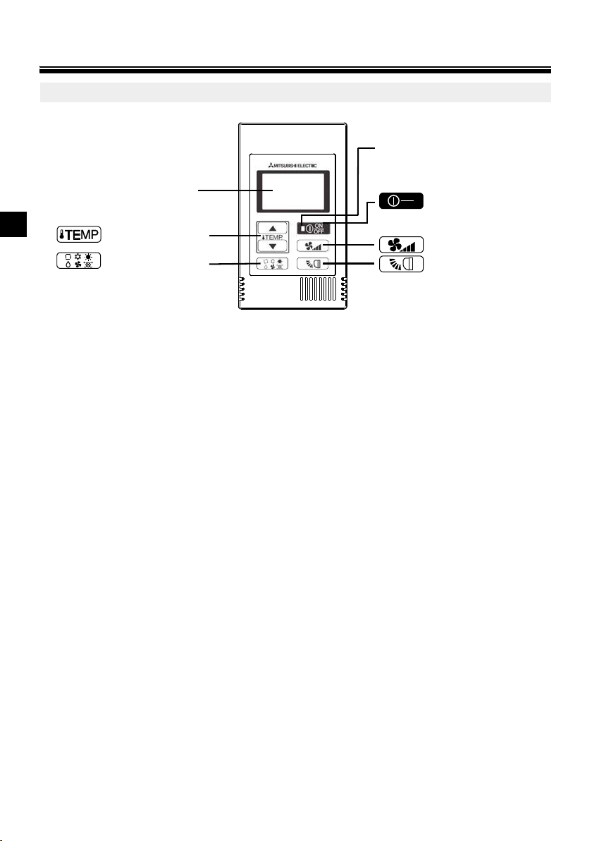
Names and functions of controller components
Backlit LCD
button (See Page 7.)
..
button (See Page 6.)
ON/OFF lamp
button
ON
OFF
button (See Page 7.)
button (See Page 8.)
* To set the functions that are not available on this controller (PAC-YT52CRA) such as Louver,
use MA remote controller or the centralized controller.
The lamp will light up in green when
turned on, and blink during startup
and when an error occurs.
Pressing this button starts and
stops the operation.
Controller interface
GB
– 4 –
Page 5

Display
*2 icon
For Mr. SLIM, when an error occurs, power indicator will blink, and refrigerant address (two digits), error code
(two digits), and unit No. will blink.
For City Multi, when an error occurs, power indicator will blink, and unit address (three digits) and error code (four
digits) will blink.
Check the error status, stop the operation, and consult your dealer.
When only error code blinks, air conditioning units stay in operation, but an error may have occurred.
Check the error code, and consult your dealer.
[Mr. SLIM] [City Multi]
[Mr. SLIM] [City Multi]
Refrigerant
address and unit
attribute appear
alternately.
Error code and
unit No. appear
alternately.
Unit address
blinks.
Error code
blinks.
Error code
blinks.
Error code
blinks.
icon appears while the unit is operated in the
energy-save mode
* All icons are displayed for explanation.
icon appears when Operation lock setting is
effective. (See page 10.)
icon appears when indoor unit functions are set up.
(Refer to the Installation Manual.)
Fan speed icon
Vane icon
icon appears when the power is on.
Indoor temperature
Operation modes
CENTRAL icon *1
CHECK icon *2
Preset temperature *3
*1 icon
Appears when one of the following local operations is prohibited: ON/OFF; operation mode; preset temperature;
fan speed; vane.
CENTRAL
*3 Preset temperature
* Centigrade or Fahrenheit is selectable. Refer to the Installation Manual for details.
In COOL, DRYING, HEAT, or
AUTO (single set point) modes In AUTO (dual set point) mode
Preset
temperature
Heating preset
temperature
Cooling preset
temperature
GB
– 5 –
Page 6

Basic operations
ON
*1 *1 *1*1, *2 *1, *3
COOL DRYING FAN AUTO HEAT VENTI.
During operation in AUTO (dual set point) mode
Preset temp.
(COOL)
Preset temp.
(HEAT)
HEAT
Room
temperature
HEATCOOL COOL
The room temperature
changes corresponding
to the change in the
outside temperature.
Operation mode
Pressing the button will change the operation mode in the following order.
*1: Not all functions are available on all models of indoor units. Functions that are not available will not
appear on the display.
*2: The preset temperature for AUTO (either single or dual set point) mode will appear depending on
GB
the indoor unit model.
*3: Available only on the Mr. SLIM unit interlocked with LOSSNAY unit.
"VENTI." will light up when LOSSNAY unit operates while the unit is in operation.
AUTO (dual set point) mode:
In AUTO (dual set point) mode, the preset temperatures can be set for cooling and heating, and
operation can be switched automatically between cooling and heating depending on the room
temperature.
The preset temperatures for cooling and heating set in AUTO (dual set point) mode will be reflected
to the temperature setting for COOL/DRYING and HEAT modes.
– 6 –
Page 7

Preset temperature
ON
..
..
Cooling preset temperature
Heating preset temperature
Current operation mode
Current preset temperature (cooling/heating) appears.
When the or button is pressed, the preset temperature
(cooling/heating) display blinks.
..
..
While the preset temperature (cooling/heating) display blinks, pressing the
button increases the preset temperatures for both cooling and
heating, and pressing the button decreases the preset temperatures
for both cooling and heating.
When the button is pressed, only the cooling preset temperature display
blinks.
..
.
While the cooling preset temperature display blinks, pressing the
button increases the cooling preset temperature, and pressing the
button decreases the cooling preset temperature.
When the button is pressed, only the heating preset temperature display
blinks.
..
..
While the heating preset temperature display blinks, pressing the
button increases the heating preset temperature, and pressing the
button decreases the heating preset temperature.
Pressing the button completes the preset temperature setting.
..
..
.
..
In COOL, DRYING, HEAT, and AUTO (single set point) modes
Pressing the button increases the preset temperature.
Pressing the
In AUTO (dual set point) mode
button decreases the preset temperature.
.
GB
* During the preset temperature setting, the setting will automatically turn off if the or
button is left untouched for a certain period of time.
– 7 –
.
Page 8

Preset temperature range is as follows.
AUTO
AUTO Setting 1 Setting 2 Setting 3 Setting 4 Setting 5 Swing
Operation mode Preset temperature range
COOL/DRYING 19 - 30°C/67 - 87°F *1
HEAT 17 - 28°C/63 - 83°F *1
AUTO (single set point) 19 - 28°C/67 - 83°F *1
AUTO (dual set point) [COOL] Preset temperature range for COOL mode.
[HEAT] Preset temperature range for HEAT mode. *2, *3
FAN, VENTI. Unsettable
*1 Preset temperature range varies depending on the indoor unit model to be connected.
Refer to the Indoor unit Instruction Book for details.
*2 The preset temperatures for cooling and heating for AUTO (dual set point) mode will be used for those for
COOL/DRYING and HEAT mode.
*3 The preset temperatures for cooling and heating can be set under the following conditions.
GB
• The cooling preset temperature is greater than the heating preset temperature.
• The difference between the cooling and heating preset temperatures is equal or greater than the minimum
temperature difference that varies depending on the indoor unit model to be connected.
Fan speed
Pressing the button will change the fan speed in the following order.
* The settable fan speed varies depending on the indoor unit model to be connected.
* If the unit has no fan setting function, the fan speed cannot be set.
In this case, the fan icon blinks when the button is pressed.
Vane
Pressing the button will switch the vane directions.
* The settable vane direction varies depending on the indoor unit model to be connected.
* If the unit has no vane function, the vane direction cannot be set.
In this case, the vane icon blinks when the button is pressed.
ON
ON
– 8 –
Page 9

Controller operation - Function settings
OFF
.
.
.
(Press the button for three seconds or longer.)
(Press the button for three
seconds or longer.)
B. Temperature range restriction for COOL/DRYING mode
D. Temperature range restriction for AUTO (single set point) mode
C. Temperature range restriction for HEAT mode
The air conditioning unit stops.
A. No temperature range
restriction
ON
OFF
Temperature range restriction
The preset temperature range for each operation mode can be restricted.
ON
(1)
OFF
(2)
(6)
(5)
(3)
(3)
(3)
1 Press the button to stop the air conditioning unit.
2 Press and hold the button for three seconds or longer to bring up the temperature range
(3)
(4)
(5)
(4)
(5)
(4)
restriction setting display. (A or B appears.)
3 Press the button to select from A through D.
* When the AUTO (single set point) mode is not available on the indoor unit, or when the AUTO
mode is set to OFF in the Mode skip setting, D will not be displayed.
A. No temperature range restriction:
The temperature range restriction will not be executed for all modes.
B. Temperature range restriction for COOL/DRYING mode:
The preset temperature range for COOL/DRYING and AUTO (dual set point) modes
can be changed.
C. Temperature range restriction for HEAT mode:
The preset temperature range for HEAT and AUTO (dual set point) modes can be
changed.
D. Temperature range restriction for AUTO (single set point) mode:
The preset temperature range for AUTO (single set point) mode can be changed.
4 Press the button to switch between the upper limit (Hi) and lower limit (Lo) settings.
GB
– 9 –
Page 10

5 Press the or button to set upper/lower limit value.
..
..
.
.
A. Operation lock is enabled. B. While the operation lock is enabled. C. Operation lock is disabled.
..
(Press the buttons for three
seconds or longer.)
A. AUTO mode
The air conditioning unit stops.
• Pressing the and buttons simultaneously can bring up the previous
.
.
temperature range of COOL/DRYING, HEAT, and AUTO modes.
• The temperature can be adjusted within the preset temperature range of the indoor unit.
Refer to the Indoor unit Instruction Book for details.
6 Press and hold the button for three seconds or longer to complete the setting.
• If this action is taken while A is displayed, the temperature range restriction will not be executed.
• If this action is taken while one of B through D is displayed, all temperature range restrictions for
COOL/ DRYING, HEAT, and AUTO modes set in B through D will be executed.
If the preset temperature range has not been changed, the restriction will not be executed.
• After the temperature range restriction is executed, if the user tries to select a temperature
outside of the range, the preset temperature display will blink.
* The temperature range on this controller (PAC-YT52CRA) connected to the indoor units that have
GB
the temperature range restriction function can be restricted also from the centralized controller
that has the same function.
Operation lock setting
This function can lock all buttons.
Locking the operations
While the operation lock is disabled ( icon is unlit.), press and hold the button for three
seconds or longer to enable the Operation lock. (A)
* While the operation lock is enabled, icon is lit. (B)
* If any button is pressed while the operation lock is enabled, icon will blink.
Unlocking the operations
While the operation lock is enabled ( icon is lit.), press and hold the button for three
seconds or longer to disable the Operation lock. (C)
Mode skip setting
The usability of AUTO mode can be set.
This setting is effective only when the controller is connected to the indoor units that have AUTO
mode.
ON
(1)
OFF
(2/4)
+
– 10 –
(3)
OFF
ON
OFF
Page 11

1 Press the button to stop the air conditioning unit.
ON
OFF
..
.
ON
OFF
..
.
.
.
(Press the buttons for three seconds or longer.)
A. Bright
The air conditioning
unit stops.
(Press the buttons for three
seconds or longer.)
B. Dark C. Light off
Auto off without
pressing any buttons.
ON
OFF
.
2 Press the and buttons simultaneously for three seconds or longer to bring up
.
the Mode skip settings display. (The current setting will appear.)
3 Press the button to select ON or OFF.
ON: AUTO mode can be selected by pressing the button during operation.
OFF: AUTO mode cannot be selected by pressing the button during operation.
4 Press the and buttons simultaneously for three seconds or longer to complete
.
the setting.
Backlight brightness setting
(1)
ON
OFF
(2)
+
(2)
+
OFF
1 Press the button to stop the air conditioning unit.
2 Press the and buttons simultaneously for three seconds or longer to change the
.
backlight brightness. (The factory setting is “bright.”)
* Repeat step 2 above to switch the settings A, B, and C.
* The setting will automatically turn off if step 2 is not performed for a certain period of time.
GB
– 11 –
Page 12

Specifications
HEAD OFFICE: TOKYO BLDG., 2-7-3, MARUNOUCHI, CHIYODA-KU, TOKYO 100-8310, JAPAN
Authorized representative in EU: MITSUBISHI ELECTRIC EUROPE B .V.
HARMAN HOUSE, 1 GEORGE STREET, UXBRIDGE, MIDDLESEX UB8 1QQ, U.K.
WT06591X01
Controller specifications
Specifications
Product size 70 (W) × 120 (H) × 14.5 (D) mm (2-3/4 × 4-3/4 × 9/16 [in])
Net weight 0.1 kg (1/4 lb.)
Rated power supply voltage 12 VDC (supplied from indoor units)
Power consumption 0.3 W
Usage environment Temperature 0 ~ 40ºC (32 ~ 104ºF)
GB
Material PC + ABS
This product is designed and intended for use in the residential, commercial,
and light-industrial environment.
The product at hand is based on the following EU regulations:
• Low Voltage Directive 2006/95/EC
• Electromagnetic Compatibility Directive 2004/108/EC
(not including the protruding part)
Humidity 30 ~ 90%RH (with no dew condensation)
– 12 –
 Loading...