

Page 1
Applicable
Model
Centralized Controller
AG-150A
Air-conditioner Control System Optional Parts
Mounting attachment A type for use with AG-150A
PAC-YG85KTB
Installation Manual
1 Safety Precautions
• Before installing the Mounting attachment A type, please read the following safety precautions carefully to ensure proper
installation.
• Observe the following precautions to ensure safety.
• The following symbols are used in this manual to indicate the type and severity of potential consequences that may result when
given instructions are not followed exactly as stated.
WARNING
CAUTION
• After the completion of installation, perform a test run to confirm proper operation.
• Retain this manual for future reference. When the unit is reinstalled or repaired, make this manual available to those who provide
these services. Make sure that the manual is passed on to any future air condition system users.
Indicates a risk of death or serious injury.
Indicates a risk of injury or damage to the product.
WARNING
Only a dealer or qualified technician should replace
the unit.
Improper replacement by an unqualified person may result
in electric shock or fire.
The Mounting attachment A type should be installed
on a surface that is strong enough to support the
weight of the unit.
If the Mounting attachment A type is installed on a surface
that lacks the strength to support it, it may fall and cause
injury.
Do not attempt to modify or repair the Mounting
attachment A type.
Modification or improper repair may result in electric shock
or fire. Consult your dealer when repairs are necessary.
Install the Mounting attachment A type properly
according to the instructions detailed in this
Installation Manual.
Improper installation by an unqualified person may result in
electric shock or fire.
Electric work must be performed by authorized
personnel according to the local regulations and the
instructions detailed in the Installation Manual.
Inadequate circuit capacity or improper installation may
result in electric shock or fire.
Ask your dealer or an authorized technician to move
the Mounting attachment A type.
Improper installation by an unqualified person may result in
electric shock or fire. Consult your dealer or a qualified
technician.
CAUTION
Do not install the Mounting attachment A type where
there is a risk of leaking flammable gas.
If the leaked gas accumulates around the Mounting
attachment A type, it may ignite and cause an explosion.
Do not use the Mounting attachment A type in an
environment that has high concentrations of oil,
steam, or sulfuric gas.
These substances may have adverse effects on the
performance of the Mounting attachment A type or
damage its parts.
Seal the wire access holes with putty to prevent dew,
water, and insects from entering to avoid electric
shock.
Do not install this Mounting attachment A type in a
place that has the potential for steam, such as a
bathroom or kitchen.
Steam may cause an electric shock or a unit malfunction.
Do not install this Mounting attachment A type where
an acid, alkaline solution, or special chemical spray is
used frequently to avoid electric shock or malfunction.
Keep the cables from coming in direct contact with the
edges of the wire access holes.
If the cables are damaged, they may cause electric shock
or fire.
This Mounting attachment A type is for exclusive use
with the AG-150A and cannot be used with other
devices.
- 1 -
Page 2
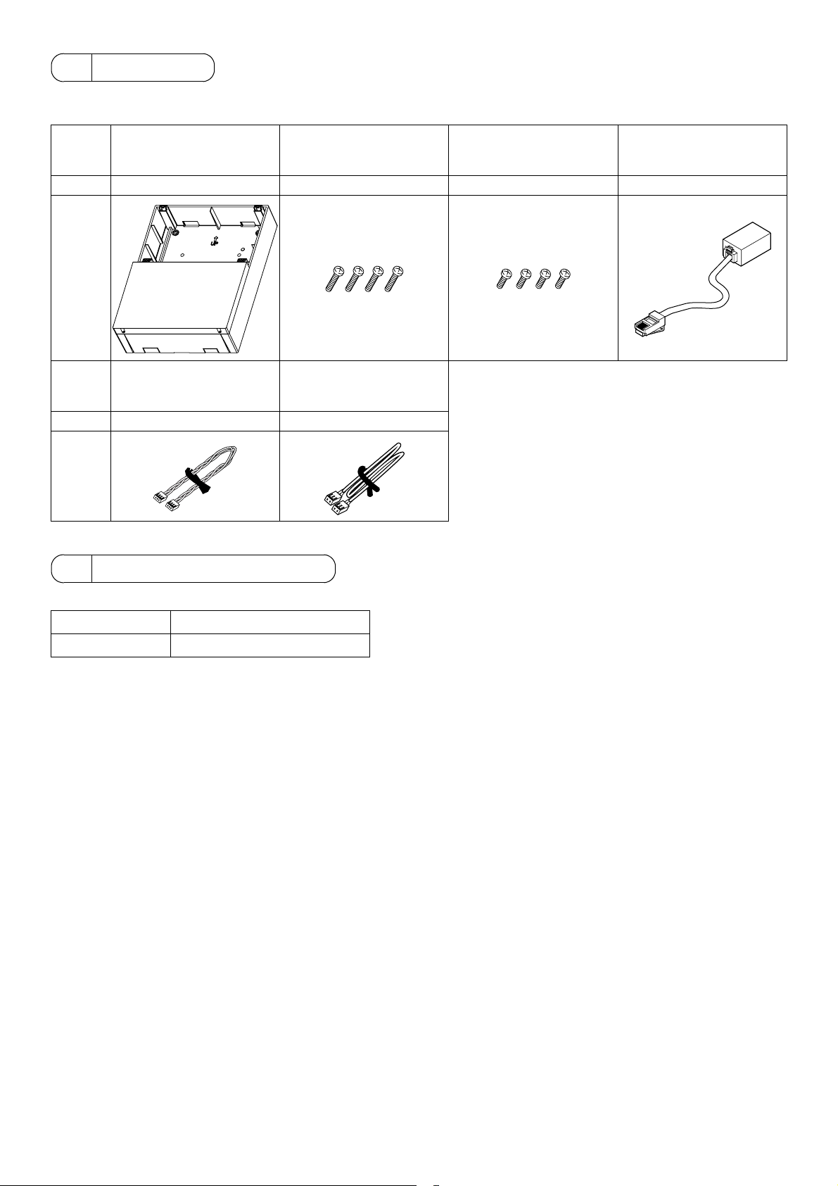
2 Parts List
The Installation Manual and the parts listed below are included with the package.
* Leave the Mounting attachment A type in the package until ready to install to protect it from damage.
1 Mounting attachment A
Name
Quantity 1 4 4 1
Shape
type (PAC-YG85KTB)
2 AG-150A mounting
screws
Roundhead screws M4×16 Roundhead screws M4×10
3 Power supply unit (PAC-
SC51KUA) mounting
screws
4 LAN link-up cable
5 Power cable for the
Name
Quantity 1 1
Shape
power supply unit (PACSC51KUA) (CN2)
6 M-NET cable for the
power supply unit (PACSC51KUA) (CN1)
3 Field-supplied parts
The following parts are necessary to mount the Mounting attachment A type (PAC-YG85KTB) and on the wall.
Name 1 Wall mounting screws (M5)
Quantity 6
Use screws that are suitable for the wall type.
The weight of the AG-150A including the Mounting attachment A type (PAC-YG85KTB) and power supply unit (PAC-SC51KUA) is
5.1 kg (12 lbs).
(The weight of the Mounting attachment A type is 1.7 kg (4 lbs.) by itself.)
Use screws with the head size of between 8 and 11.8 mm (3/8 and 1/2 in).
- 2 -
Page 3
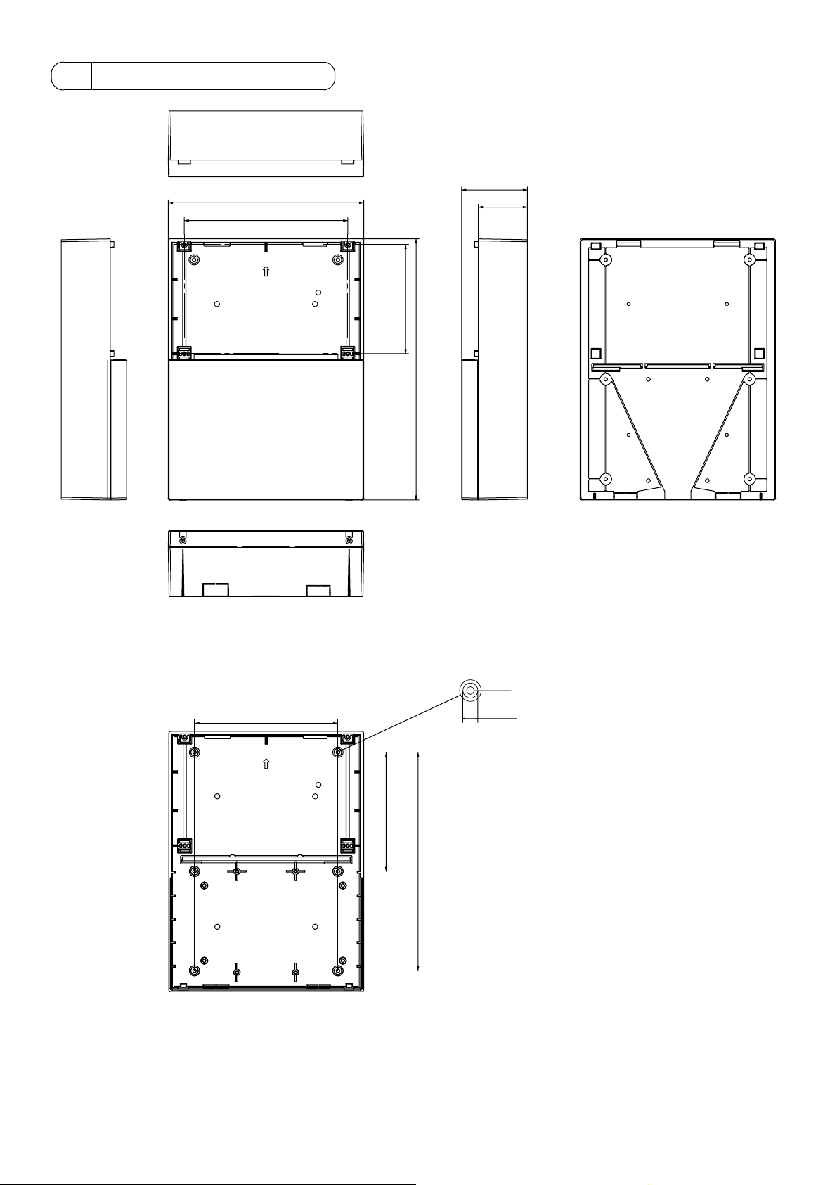
4 External Dimensions
299(11-
250(9-7/8)
UP
13
/16)
/8)
5
75(3)
167(6-
100.6(4)
/4)
3
399(15-
Under the cover
>PC+ABS<
220(8-
UP
Wall mounting screw hole (6)
1
ø5.5 (
)
/
4
1
12 (
)
/
11
/16)
/16)
3
182.5(7-
/4)
1
2
335(13-
Unit: mm (in)
- 3 -
Page 4
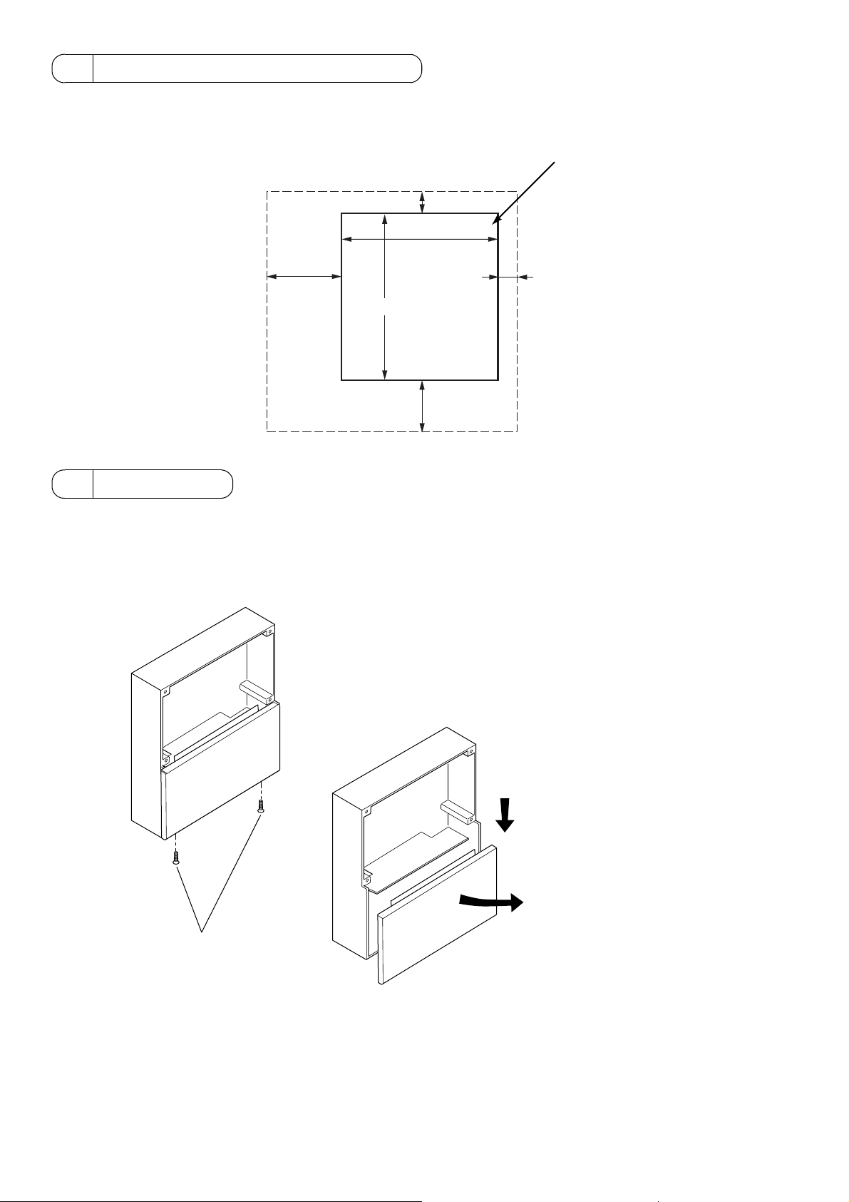
5 Selecting an Installation Site
1. Required installation space
Install the Mounting attachment A type (PAC-YG85KTB) where the space indicated in the figure below can be secured.
Mounting attachment A type (PAC-YG85KTB)
3
/16)
30 (1-
13
299 (11-
/16
)
151 (6)
399(15-
3
/4
)
13
121 (4-
/16
)
30 (1-
3
/16)
Unit: mm (in)
6Installation
The cable can be routed either from the top or the bottom.
1. To route the cable from the top
(1) Remove the cover of Mounting attachment A type.
To remove the cover, unscrew the two screws at the bottom of the cover, slide down the cover slightly, and pull it forward.
1 Unscrew the two screws.
2 Slide down the cover.
3 Pull the cover forward.
- 4 -
Page 5

(2) Cut out the knockout hole on the Mounting attachment A type (PAC-YG85KTB) at the top with a nipper for the cable
(the thin part of the plastic).
UP
>PC+ABS<
NOTE
Install the Mounting attachment A type (PAC-YG85KTB)
so that the arrow (ÇUP) on the back of it points up.
(3) Sand the cut surface of the knockout hole smooth.
CAUTION
Any rough edges that are left may damage the cable and cause electric shock or fire.
(4) Install the Mounting attachment A type (PAC-YG85KTB) with
the six mounting screws (field-supplied).
Use screws that are suitable for the wall type.
Install it on the surface strong enough to support its weight.
Wall
NOTE
Install the Mounting attachment A type (PAC-YG85KTB)
so that the arrow (ÇUP) on the back of it points up.
M5 screws (field-supplied)
- 5 -
Page 6

(5) Push the cable through the knockout hole.
knockout hole
Wall
Protective earth (ground) cable
AC power cable
M-NET transmission cable
(6) Install the power supply unit (PAC-SC51KUA; sold separately) inside the Mounting attachment A type with the four M4 screws
(supplied).
Power supply unit
(PAC-SC51KUA;
sold separately)
(weight 1.4kg)
M4 screws (supplied
with PAC-YG85KTB)
(7) Connect the cables to the power supply unit (PAC-SC51KUA). Refer to the PAC-SC51KUA Installation Manual for details.
(8) Remove AG-150A surface cover.
Insert a flat-tip screwdriver in the holes
indicated and move the handle up to
remove the cover.
- 6 -
Page 7

(9) Connect the wiring from the power supply unit to the
centralized controller.
Back of AG-150A
DC power cable
M-NET transmission cable
(Supplied)
DC power cable
(Supplied)
M-NET
transmission
cable
DC power line and M-NET transmission cable are connected using a connector as shown figure below. Connectable to the
connector using the cable that is supplied.
Power supply unit
(PAC-SC51KUA)
Centralized controller
(AG-150A)
M-NET transmission line
(Centralized controll line)
DC power supply line (24VDC)
*Polarized
M-NET transmission line (Centralized control line)
- 7 -
DC power supply line (24VDC) *Polarized
Page 8

(10) If the AG-150A is not always connected to the LAN, connect the supplied LAN link-up cable to the LAN connector.
(* If the AG-150A is always connected to the LAN, connect the LAN cable (field supplied) via a HUB and the LAN link-up
cable is not required.)
LAN
LAN link-up cable (supplied)
(11) To use the external I/O, connect the external I/O cable (PAC-YG10HA; sold separately) to CN5 on the AG-150A.
NOTE
• When connecting the external input/output cables to connector
CN5 on the controller, punch out the knockout hole.
(12) Securely seal the cable lead-in port with putty to prevent dew, water and insect, etc. from entering.
Seal with putty
Punch out the knockout hole
- 8 -
Page 9

(13) Install the controller inside the Mounting attachment A type with the four M4 rounded screws (supplied).
If the LAN link-up cable is used, place it inside the Mounting attachment A type as shown in the figure below.
LAN link-up cable
(14) Attach the cover on the AG-150A.
(15) Attach the power supply unit cover with the two screws.
2
1
3
- 9 -
Page 10

2. To route the cable from the bottom
(1) Remove the cover of Mounting attachment A type.
(Refer to section 1.(1).)
(2) Cut out the knockout hole on the Mounting attachment A type (PAC-YG85KTB) at the bottom with a nipper for the cable.
NOTE
Install the Mounting attachment A type (PAC-YG85KTB) so that
the arrow (ÇUP) on the back of it points up.
(3) Sand the cut surface of the knockout hole smooth.
CAUTION
Any rough edges that are left may damage the cable and cause electric shock or fire.
(4) Install the Mounting attachment A type (PAC-YG85KTB) with
the six mounting screws (field-supplied).
Use screws that are suitable for the wall type.
Install it on the surface strong enough to support its weight.
(Refer to section 1.(4).)
(5) Push the cable through the knockout hole.
Wall
NOTE
Install the Mounting attachment A type (PAC-YG85KTB)
so that the arrow (ÇUP) on the back of it points up.
Knockout hole
Protective earth (ground) cable
AC power cable
M-NET transmission cable
- 10 -
Page 11

(6) Install the power supply unit (PAC-SC51KUA; sold separately) inside the Mounting attachment A type with the four M4 screws
(supplied).
(Refer to section 1.(6).)
(7) Connect the cables to the power supply unit (PAC-SC51KUA).
Refer to the PAC-SC51KUA Installation Manual for details.
(8) Remove the AG-150A surface cover.
(9) Connect the wiring from the power supply unit to the centralized controller.
(Refer to section 1.(9).)
(10) If the AG-150A is not always connected to the LAN, connect the supplied LAN link-up cable to the LAN connector.
(* If the AG-150A is always connected to the LAN, connect the LAN cable (field supplied) via a HUB and the LAN link-up
cable is not required.)
(11) To use the external I/O, connect the external I/O cable (PAC-YG10HA; sold separately) to CN5 on the AG-150A.
(12) Install the centralized controller inside the Mounting attachment A type with the four M4 screws (supplied).
If the LAN link-up cable is used, place it inside the Mounting attachment A type.
(Refer to section 1.(13).)
(13) Attach the cover on the AG-150A.
(14) Attach the power supply unit cover with the two screws.
(Refer to section 1.(15).)
7 LAN link-up cable
The LAN link-up cable is used for maintenance purpose when the AG-150A is not always connected to the LAN.
If the AG-150A is not always connected to the LAN, connect a LAN cable to the LAN link-up cable to upgrade the AG-150A software
as necessary.
LAN link-up cable
LAN cable
PC
Remove the cover of Mounting attachment A type to use the LAN link-up cable.
Refer to section 1.(1) in 6. Installation for how to remove the cover.
- 11 -
Page 12

Please be sure to put the contact address/telephone number on
this manual before handing it to the customer.
HEAD OFFICE: TOKYO BLDG. , 2-7-3, MARUNOUCHI, CHIYODA-KU, TOKYO 100-8310, JAPAN
Authorized representative in EU: MITSUBISHI ELECTRIC EUROPE B.V.
HARMAN HOUSE, 1 GEORGE STREET, UXBRIDGE, MIDDLESEX UB8 1QQ, U.K.
WT05423X01
Printed in Japan
Recycled Paper
 Loading...