

Mitsubishi MDS-EJH-V1, MDS-EMH-SPV3, MDS-EH Series, MDS-EJSP, MDS-E-CV Instruction Manual
...Page 1

Page 2

Introduction
Thank you for selecting the Mitsubishi numerical control unit. This instruction manual describes the handling and
caution points for using this AC servo/spindle. Incorrect handling may lead to unforeseen accidents, so always read
this instruction manual thoroughly to ensure correct usage.
Make sure that this instruction manual is delivered to the end user. Always store this manual in a safe place.
In order to confirm if all function specifications described in this manual are applicable, refer to the specifications for
each CNC.
Notes on Reading This Manual
(1) Since the description of this specification manual deals with NC in general, for the specifications of individual
machine tools, refer to the manuals issued by the respective machine tool builders. The "restrictions" and
"available functions" described in the manuals issued by the machine tool builders have precedence to those
in this manual.
(2) This manual describes as many special operations as possible, but it should be kept in mind that items not
mentioned in this manual cannot be performed.
In this manual, the following abbreviations might be used.
MTB: Machine tool builder
Page 3

Page 4

Precautions for Safety
Please read this manual and auxiliary documents before starting installation, operation, maintenance or inspection
to ensure correct usage. Thoroughly understand the device, safety information and precautions before starting
operation.
The safety precautions in this instruction manual are ranked as "WARNING" and "CAUTION".
DANGER
When there is a potential risk of fatal or serious injuries if handling is mistaken.
WARNING
When a dangerous situation, or fatal or serious injuries may occur if handling is mistaken.
CAUTION
When a dangerous situation may occur if handling is mistaken leading to medium or minor injuries, or physical damage.
Note that some items described as " CAUTION" may lead to major results depending on the situation. In any
case, important information that must be observed is described.
Page 5
The signs indicating prohibited and mandatory matters are explained below.
Indicates a prohibited matter. For example, "Fire Prohibited" is indicated as .
Indicates a mandatory matter. For example, grounding is indicated as .
The meaning of each pictorial sign is as follows.
object
CAUTION HOT
KEEP FIRE AWAY General instruction
Danger Electric shock
CAUTION
Prohibited
After reading this specifications and instructions manual, store it where the user can access it easily for reference.
The numeric control unit is configured of the control unit, operation board, servo drive unit, spindle drive unit, power
supply, servo motor and spindle motor, etc.
In this section "Precautions for safety", the following items are generically called the "motor".
• Servo motor
• Linear servo motor
• Spindle motor
• Direct-drive motor
In this section "Precautions for safety", the following items are generically called the "unit".
• Servo drive unit
• Spindle drive unit
• Power supply unit
• Scale interface unit
• Magnetic pole detection unit
CAUTION rotated
Disassembly is
prohibited
risk
Danger explosive
Earth ground
POINT
Important matters that should be understood for operation of this machine are indicated as a POINT in this manual.
For Safe Use
Mitsubishi CNC is designed and manufactured solely for applications to machine tools to be used for industrial
purposes.
Do not use this product in any applications other than those specified above, especially those which are
substantially influential on the public interest or which are expected to have significant influence on human lives or
properties.
Page 6

1. Electric shock prevention
Make sure the power is shut OFF before connecting a unit and a motor to the power.
Do not open the front cover while the power is ON or during operation. Failure to observe this could lead to
electric shocks.
Do not operate the unit with the front cover removed. The high voltage terminals and charged sections will
be exposed, and can cause electric shocks.
Do not remove the front cover and connector even when the power is OFF unless carrying out wiring work
or periodic inspections. The inside of the units is charged, and can cause electric shocks.
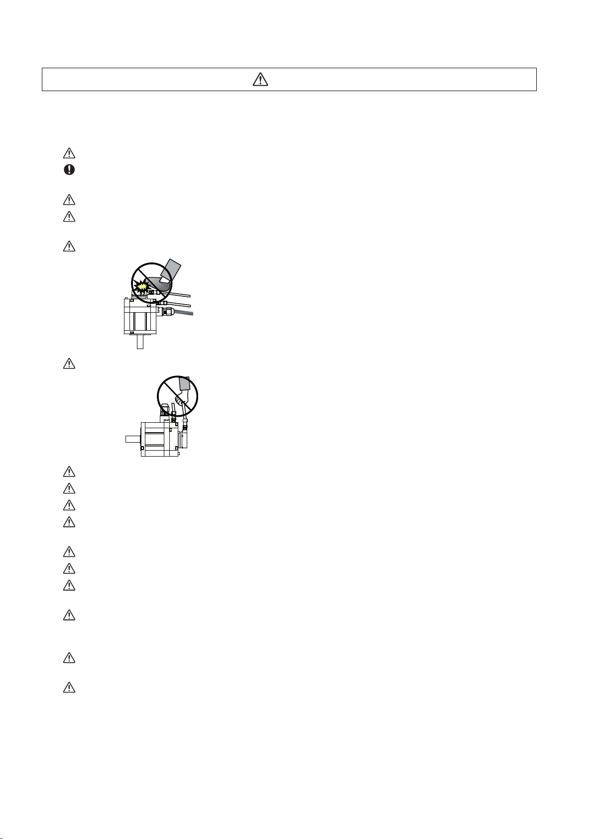
Since the high voltage is supplied to the main circuit connector while the power is ON or during operation,
do not touch the main circuit connector with an adjustment screwdriver or the pen tip. Failure to observe
this could lead to electric shocks.
Wait at least 15 minutes after turning the power OFF, confirm that the CHARGE lamp has gone out, and
check the voltage between P and N terminals with a tester, etc., before starting wiring, maintenance or
inspections. Failure to observe this could lead to electric shocks.
Ground the unit and motor. For the motor, ground it via the drive unit.
Wiring, maintenance and inspection work must be done by a qualified technician.
Wire the servo drive unit and servo motor after installation. Failure to observe this could lead to electric
shocks.
Do not touch the switches with wet hands. Failure to observe this could lead to electric shocks.
Do not damage, apply forcible stress, place heavy items on the cables or get them caught. Failure to
observe this could lead to electric shocks.
Always insulate the power terminal connection section. Failure to observe this could lead to electric
shocks.
After assembling the built-in IPM/SPM spindle motor, if the rotor is rotated by hand etc., voltage occurs
between the terminals of lead. Take care not to get electric shocks.
WARNING
Page 7

2. Injury prevention
When handling a motor, perform operations in safe clothing.
In the system where the optical communication with CNC is executed, do not see directly the light
generated from CN1A/CN1B connector of drive unit or the end of cable. When the light gets into eye, you
may feel something is wrong for eye.
(The light source of optical communication corresponds to class1 defined in JISC6802 or IEC60825-1.)
The linear servo motor, direct-drive motor and built-in IPM/SPM spindle motor uses permanent magnets in
the rotor, so observe the following precautions.
(1)Handling
• The linear servo motor, direct-drive motor and built-in IPM/SPM spindle motor could adversely affect
medical electronics such as pacemakers, etc., therefore, do not approach the rotor.
• Do not place magnetic materials as iron.
• When a magnetic material as iron is placed, take safety measure not to pinch fingers or hands due to
the magnetic attraction force.
• Remove metal items such as watch, piercing jewelry, necklace, etc.
• Do not place portable items that could malfunction or fail due to the influence of the magnetic force.
• When the rotor is not securely fixed to the machine or device, do not leave it unattended but store it
in the package properly.
• When installing the motor to the machine, take it out from the package one by one, and then install it.
• It is highly dangerous to lay out the motor or magnetic plates together on the table or pallet, therefore
never do so.
(2)Transportation and storage
• Correctly store the rotor in the package to transport and store.
• During transportation and storage, draw people's attention by applying a notice saying "Strong
magnet-Handle with care" to the package or storage shelf.
• Do not use a damaged package.
(3)Installation
• Take special care not to pinch fingers, etc., when installing (and unpacking) the linear servo motor.
WARNING
Page 8

1. Fire prevention
Install the units, motors and regenerative resistor on non-combustible material. Direct installation on
combustible material or near combustible materials could lead to fires.
Always install a circuit protector and contactor on the servo drive unit power input as explained in this
manual. Refer to this manual and select the correct circuit protector and contactor. An incorrect selection
could result in fire.
Shut off the power on the unit side if a fault occurs in the units. Fires could be caused if a large current
continues to flow.
When using a regenerative resistor, provide a sequence that shuts off the power with the regenerative
resistor's error signal. The regenerative resistor could abnormally overheat and cause a fire due to a fault
in the regenerative transistor, etc.
The battery unit could heat up, ignite or rupture if submerged in water, or if the poles are incorrectly wired.
Cut off the main circuit power with the contactor when an alarm or emergency stop occurs.
2. Injury prevention
Do not apply a voltage other than that specified in this manual, on each terminal. Failure to observe this
item could lead to ruptures or damage, etc.
Do not mistake the terminal connections. Failure to observe this item could lead to ruptures or damage,
etc.
Do not mistake the polarity (+,- ). Failure to observe this item could lead to ruptures or damage, etc.
Do not touch the radiation fin on unit back face, regenerative resistor or motor, etc., or place parts (cables,
etc.) while the power is turned ON or immediately after turning the power OFF. These parts may reach high
temperatures, and can cause burns or part damage.
Structure the cooling fan on the unit back face, etc., so that it cannot be touched after installation.
Touching the cooling fan during operation could lead to injuries.
Take care not to suck hair, clothes, etc. into the cooling fan.
CAUTION
Page 9
CAUTION
3. Various precautions
Observe the following precautions. Incorrect handling of the unit could lead to faults, injuries and electric shocks, etc.
(1) Transportation and installation
Correctly transport the product according to its weight.
Use the motor's hanging bolts only when transporting the motor itself. Do not use the motor's hanging
bolts to transport a motor with other parts installed, or to transport a machine with a motor installed.
Do not stack the products above the tolerable number.
Follow this manual and install the unit or motor securely in a place where it can be borne and
noncombustible. Insufficient fixing could lead to the unit or the motor slipping off during operation.
Do not get on top of or place heavy objects on the unit.
Do not hold the cables, axis or encoder when transporting the motor.
Do not hold the connected wires or cables when transporting the units.
Do not hold the front cover when transporting the unit. The unit could drop.
Always observe the installation directions of the units or motors.
Secure the specified distance between the units and control panel, or between the servo drive unit and
other devices.
Do not install or run a unit or motor that is damaged or missing parts.
Do not block the intake or exhaust ports of the motor provided with a cooling fan.
Do not let foreign objects enter the units or motors. In particular, if conductive objects such as screws or
metal chips, etc., or combustible materials such as oil enter, rupture or breakage could occur.
Provide adequate protection using a material such as connector for conduit to prevent screws, metallic
detritus, water and other conductive matter or oil and other combustible matter from entering the motor
through the power line lead-out port.
The units, motors and encoders are precision devices, so do not drop them or apply strong impacts to
them.
Always operate the motor, which has a shaft with keyway, with the key attached.
Page 10
CAUTION
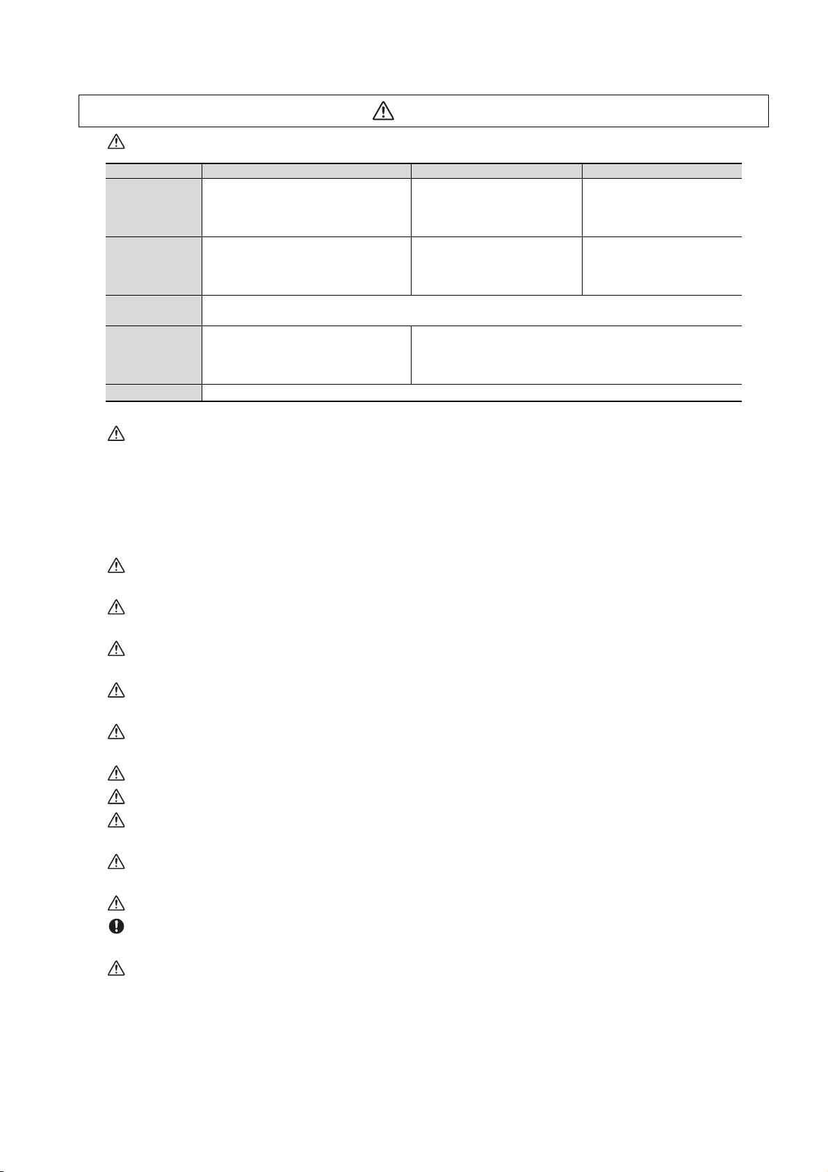
Store and use the units under the following environment conditions.
Environment Unit Servo motor Spindle motor
Operation: 0 to +55°C
Ambient
temperature
Ambient
humidity
Atmosphere
Altitude
Vibration/impact According to each unit or motor specification
Storage / Transportation: -15°C to +70°C
Storage / Transportation: 90%RH or less
1000 meters or less above sea level,
13000 meters or less above sea level
(with no freezing),
(with no freezing)
Operation: 90%RH or less
(with no dew condensation)
(with no dew condensation)
With no corrosive gas, inflammable gas, oil mist, dust or conductive fine particles
Operation/Storage:
Transportation:
(Note) For details, confirm each unit or motor specifications in addition.
When disinfectants or insecticides must be used to treat wood packaging materials, always use methods
other than fumigation (for example, apply heat treatment at the minimum wood core temperature of 56 °C
for a minimum duration of 30 minutes (ISPM No. 15 (2009))).
If products such as units are directly fumigated or packed with fumigated wooden materials, halogen
substances (including fluorine, chlorine, bromine and iodine) contained in fumes may contribute to the
erosion of the capacitors.
When exporting the products, make sure to comply with the laws and regulations of each country.
Do not use the products in conjunction with any components that contain halogenated flame retardants
(bromine, etc). Failure to observe this may cause the erosion of the capacitors.
Securely fix the servo motor to the machine. Insufficient fixing could lead to the servo motor slipping off
during operation.
Always install the servo motor with reduction gear in the designated direction. Failure to do so could lead
to oil leaks.
Structure the rotary sections of the motor so that it can never be touched during operation. Install a cover,
etc., on the shaft.
When installing a coupling to a servo motor shaft end, do not apply an impact by hammering, etc. The
encoder could be damaged.
Do not apply a load exceeding the tolerable load onto the servo motor shaft. The shaft could break.
Store the motor in the package box.
When inserting the shaft into the built-in IPM/SPM spindle motor, do not heat the rotor higher than 130°C.
The magnet could be demagnetized, and the specifications characteristics will not be ensured.
Always use a nonmagnetic tool (explosion-proof beryllium copper alloy safety tool: NGK Insulators, etc.)
when installing the built-in IPM/SPM spindle motor, direct-drive motor and linear servo motor.
Always provide a mechanical stopper on the end of the linear servo motor's travel path.
If the unit has been stored for a long time, always check the operation before starting actual operation.
Please contact the Service Center, Sales Office or dealer.
Install the heavy peripheral devices to the lower part in the panel and securely fix it not to be moved due to
vibration.
Operation: 0 to +40°C
(with no freezing),
Storage: -15°C to +70°C
(with no freezing)
Operation: 80%RH or less
(with no dew condensation),
Storage: 90%RH or less
(with no dew condensation)
Indoors (no direct sunlight)
1000 meters or less above sea level,
10000 meters or less above sea level
Operation: 0 to +40°C
(with no freezing),
Storage: -20°C to +65°C
(with no freezing)
Operation: 90%RH or less
(with no dew condensation)
Storage: 90%RH or less
(with no dew condensation)
Operation/Storage:
Transportation:
Page 11
CAUTION
RA
24G
RA
24G
Servo drive unit
Servo drive unit
Control output
signal
Control output
signal
(2) Wiring
Correctly and securely perform the wiring. Failure to do so could lead to abnormal operation of the motor.
Do not install a condensing capacitor, surge absorber or radio noise filter on the output side of the drive
unit.
Correctly connect the output side of the drive unit (terminals U, V, W). Failure to do so could lead to
abnormal operation of the motor.
When using a power regenerative power supply unit, always install an AC reactor for each power supply
unit.
In the main circuit power supply side of the unit, always install an appropriate circuit protector or contactor
for each unit. Circuit protector or contactor cannot be shared by several units.
Always connect the motor to the drive unit's output terminals (U, V, W).
Do not directly connect a commercial power supply to the servo motor. Failure to observe this could result
in a fault.
When using an inductive load such as a relay, always connect a diode as a noise measure parallel to the
load.
When using a capacitance load such as a lamp, always connect a protective resistor as a noise measure
serial to the load.
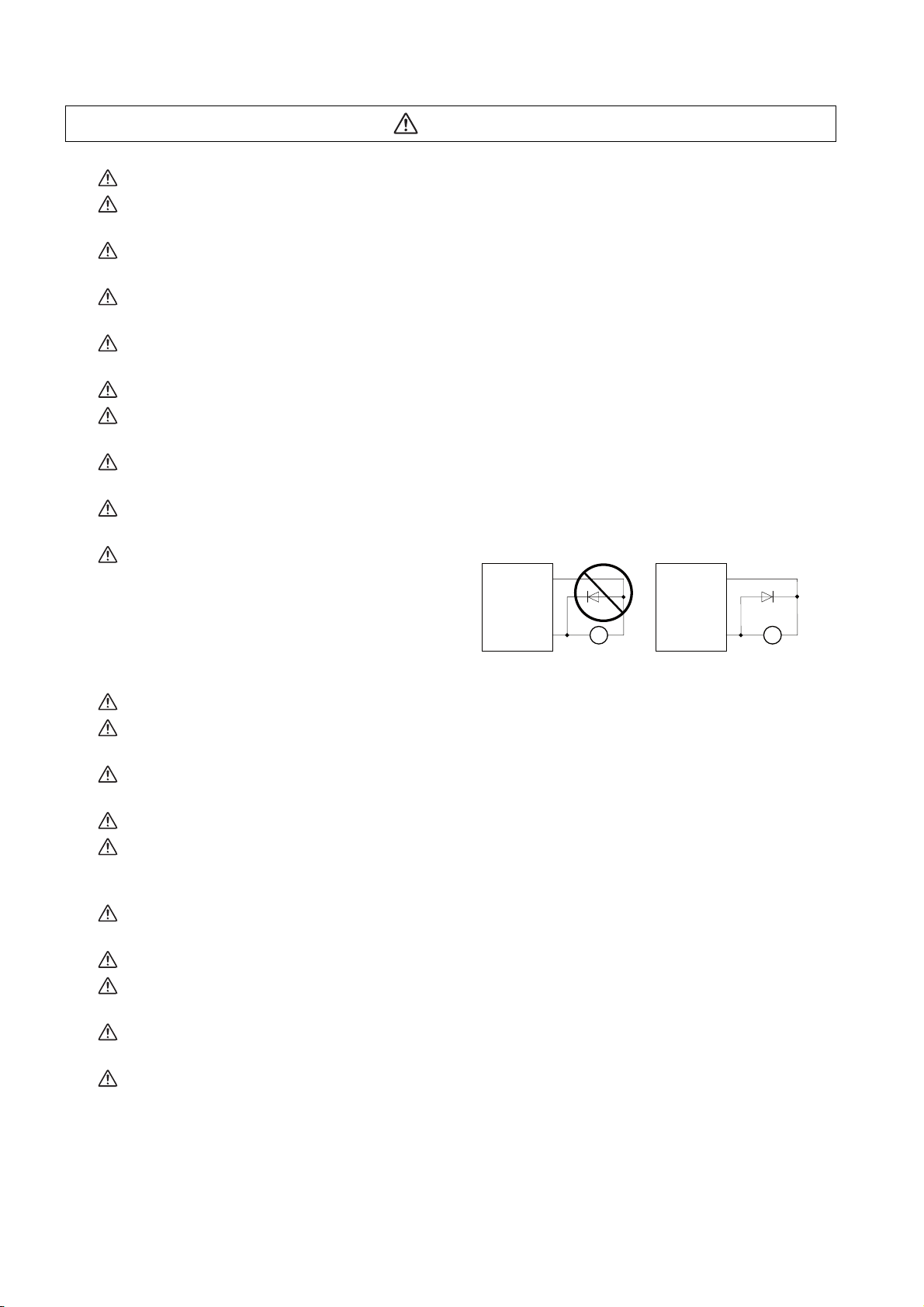
Do not reverse the direction of a diode which
connect to a DC relay for the control output
signals such as contractor and motor brake
output, etc. to suppress a surge. Connecting it
backwards could cause the drive unit to
malfunction so that signals are not output, and
emergency stop and other safety circuits are inoperable.
Do not connect/disconnect the cables connected between the units while the power is ON.
Securely tighten the cable connector fixing screw or fixing mechanism. An insecure fixing could cause the
cable to fall off while the power is ON.
When using a shielded cable instructed in the instruction manual, always ground the cable with a cable
clamp, etc. (Refer to "EMC Installation Guidelines")
Always separate the signals wires from the power line.
Use wires and cables that have a wire diameter, heat resistance and flexibility that conforms to the system.
(3) Trial operation and adjustment
Check and adjust each program and parameter before starting operation. Failure to do so could lead to
unforeseen operation of the machine.
Do not make remarkable adjustments and changes of parameter as the operation could become unstable.
The usable motor and unit combination is predetermined. Always check the combinations and parameters
before starting trial operation.
The direct-drive motor and linear servo motor do not have a stopping device such as magnetic brakes.
Install a stopping device on the machine side.
When using the linear servo motor for an unbalance axis, adjust the unbalance weight to 0 by installing an
air cylinder, etc. on the machine side. The unbalance weight disables the initial magnetic pole adjustment.
Page 12

CAUTION
(4) Usage methods
In abnormal state, install an external emergency stop circuit so that the operation can be stopped and
power shut off immediately.
Turn the power OFF immediately if smoke, abnormal noise or odors are generated from the unit or motor.
Do not disassemble or repair this product.
Never make modifications.
When an alarm occurs, the machine will start suddenly if an alarm reset (RST) is carried out while an
operation start signal (ST) is being input. Always confirm that the operation signal is OFF before carrying
out an alarm reset. Failure to do so could lead to accidents or injuries.
Reduce magnetic damage by installing a noise filter. The electronic devices used near the unit could be
affected by magnetic noise. Install a line noise filter, etc., if there is a risk of magnetic noise.
Use the unit, motor and regenerative resistor with the designated combination. Failure to do so could lead
to fires or trouble.
The brake (magnetic brake) of the servo motor are for holding, and must not be used for normal braking.
There may be cases when holding is not possible due to the magnetic brake's life, the machine
construction (when ball screw and servo motor are coupled via a timing belt, etc.) or the magnetic brake's
failure. Install a stop device to ensure safety on the machine side.
After changing the programs/parameters or after maintenance and inspection, always test the operation
before starting actual operation.
Do not enter the movable range of the machine during automatic operation. Never place body parts near or
touch the spindle during rotation.
Follow the power supply specification conditions given in each specification for the power (input voltage,
input frequency, etc.).
Set all bits to "0" if they are indicated as not used or empty in the explanation on the bits.
Do not use the dynamic brakes except during the emergency stop. Continued use of the dynamic brakes
could result in brake damage.
If a circuit protector for the main circuit power supply is shared by several units, the circuit protector may
not activate when a short-circuit fault occurs in a small capacity unit. This is dangerous, so never share the
circuit protector.
Mitsubishi spindle motor is dedicated to machine tools. Do not use for other purposes.
(5) Troubleshooting
If a hazardous situation is predicted during power failure or product trouble, use a servo motor with
magnetic brakes or install an external brake mechanism.
Always turn the main circuit power of the motor OFF when an alarm occurs.
If an alarm occurs, remove the cause, and secure the safety before resetting the alarm.
Page 13

CAUTION
(6) Maintenance, inspection and part replacement
Always backup the programs and parameters before starting maintenance or inspections.
The capacity of the electrolytic capacitor will drop over time due to self-discharging, etc. To prevent
secondary disasters due to failures, replacing this part every five years when used under a normal
environment is recommended. Contact the Service Center, Service Station, Sales Office or dealer for
repairs or part replacement.
Never perform a megger test (measure the insulation resistance) of the drive unit. Failure to observe this
could lead to faults.
If the battery low warning is issued, immediately replace the battery. Replace the batteries while applying
the drive unit's control power.
Do not short circuit, charge, overheat, incinerate or disassemble the battery.
For after-purchase servicing of the built-in motor, only the servicing parts for MITSUBISHI encoder can be
supplied. For the motor body, prepare the spare parts at the machine tool builders.
For maintenance, part replacement, and services in case of failures in the built-in motor (including the
encoder), take necessary actions at the machine tool builders. For drive unit, Mitsubishi can offer the afterpurchase servicing as with the general drive unit.
(7) Disposal
Take the batteries and backlights for LCD, etc., off from the controller, drive unit and motor, and dispose of
them as general industrial wastes.
Do not disassemble the unit or motor.
Dispose of the battery according to local laws.
Always return the secondary side (magnet side) of the linear servo motor to the Service Center or Service
Station.
When incinerating optical communication cable, hydrogen fluoride gas or hydrogen chloride gas which is
corrosive and harmful may be generated. For disposal of optical communication cable, request for
specialized industrial waste disposal services that has incineration facility for disposing hydrogen fluoride
gas or hydrogen chloride gas.
(8) Transportation
The unit and motor are precision parts and must be handled carefully.
According to a United Nations Advisory, the battery unit and battery must be transported according to the
rules set forth by the International Civil Aviation Organization (ICAO), International Air Transportation
Association (IATA), International Maritime Organization (IMO), and United States Department of
Transportation (DOT), etc.
(9) General precautions
The drawings given in this manual show the covers and safety partitions, etc., removed to provide a clearer
explanation. Always return the covers or partitions to their respective places before starting operation, and
always follow the instructions given in this manual.
Page 14

Treatment of waste
The following two laws will apply when disposing of this product. Considerations must be made to each law.
The following laws are in effect in Japan. Thus, when using this product overseas, the local laws will have a
priority. If necessary, indicate or notify these laws to the final user of the product.
(1) Requirements for "Law for Promotion of Effective Utilization of Resources"
(a) Recycle as much of this product as possible when finished with use.
(b) When recycling, often parts are sorted into steel scraps and electric parts, etc., and sold to scrap
contractors. Mitsubishi recommends sorting the product and selling the members to appropriate
contractors.
(2) Requirements for "Law for Treatment of Waste and Cleaning"
(a) Mitsubishi recommends recycling and selling the pr oduct when n o longer needed a ccording to item
(1) above. The user should make an effort to reduce waste in this manner.
(b) When disposing a product that cannot be resold, it shall be treated as a waste product.
(c) The treatment of industrial waste must be commissioned to a licensed industrial waste treatment
contractor, and appropriate measures, including a manifest co ntrol, must be taken.
(d) Batteries correspond to "primary batteries", and must be disposed of according to local disposal
laws.
Page 15

Page 16

Disposal
(Note) This symbol mark is for EU countries only.
This symbol mark is according to the directive 2006/66/EC Article 20 Information for endusers and Annex II.
Your MITSUBISHI ELECTRIC product is designed and manufactured with high quality materials and
components which can be recycled and/or reused.
This symbol means that batteries and accumulators, at their end-of-life, should be disposed of
separately from your household waste.
If a chemical symbol is printed beneath the symbol shown above, this chemical symbol means that the
battery or accumulator contains a heavy metal at a certain concentration. This will be indicated as
follows:
Hg: mercury (0,0005%), Cd: cadmium (0,002%), Pb: lead (0,004%)
In the European Union there are separate collection systems for used batteries and accumulators.
Please, dispose of batteries and accumulators correctly at your local community waste collection/
recycling centre.
Please, help us to conserve the environment we live in!
Page 17

Page 18

Trademarks
MELDAS, MELSEC, EZSocket, EZMotion, iQ Platform, MELSOFT, GOT, CC-Link, CC-Link/LT and CC-Link
IE are either trademarks or registered trademarks of Mitsubishi Electric Co rporation in Japan and/or other
countries.
Other company and product names that appear in this manual are trademarks or registe red trademarks of t he
respective companies.
Page 19

Page 20

本製品の取扱いについて
( 日本語 /Japanese)
本製品は工業用 ( クラス A) 電磁環境適合機器です。販売者あるいは使用者はこの点に注意し、住商業環境以外で
の使用をお願いいたします。
Handling of our product
(English)
This is a class A product. In a domestic environment this product may cause radio interference in which case the
user may be required to take adequate measures.
본 제품의 취급에 대해서
( 한국어 /Korean)
이 기기는 업무용 (A 급 ) 전자파적합기기로서 판매자 또는 사용자는 이 점을 주의하시기 바라며 가정외의 지역에
서 사용하는 것을 목적으로 합니다 .
Page 21

Page 22

Contents
1 Installation .................................................................................................................................................... 1
1.1 Installation of Servo Motor.....................................................................................................................................2
1.1.1 Environmental Conditions ............................................................................................................................2
1.1.2 Quakeproof Level ...........................................................................................................................................3
1.1.3 Cautions for Mounting Load (Prevention of Impact on Shaft) ................................................................... 4
1.1.4 Installation Direction...................................................................................................................................... 4
1.1.5 Shaft Characteristics ..................................................................................................................................... 5
1.1.6 Machine Accuracy.......................................................................................................................................... 6
1.1.7 Coupling with the Load.................................................................................................................................. 7
1.1.8 Oil / Water Standards .....................................................................................................................................8
1.1.9 Installation of Servo Motor .......................................................................................................................... 11
1.1.10 Cable Stress................................................................................................................................................11
1.2 Installation of Spindle Motor................................................................................................................................ 12
1.2.1 Environmental Conditions ..........................................................................................................................12
1.2.2 Balancing the Spindle Motor (Unit).............................................................................................................13
1.2.3 Shaft Characteristics ................................................................................................................................... 15
1.2.4 Machine Accuracy........................................................................................................................................15
1.2.5 Coupling with the Fittings ...........................................................................................................................16
1.2.6 Installation of Rotary Joint and Coolant Joint (Hollow Shaft Specifications) ........................................ 16
1.2.7 Ambient Environment .................................................................................................................................. 22
1.2.8 Installation of Spindle Motor ....................................................................................................................... 22
1.2.9 Connection.................................................................................................................................................... 23
1.2.10 Cable............................................................................................................................................................24
1.3 Installation of Tool Spindle Motor ....................................................................................................................... 25
1.3.1 Environmental Conditions ..........................................................................................................................25
1.3.2 Shaft Characteristics ................................................................................................................................... 25
1.3.3 Installation of Tool Spindle Motor............................................................................................................... 25
1.4 Installation of the Drive Unit ................................................................................................................................26
1.4.1 Environmental Conditions ..........................................................................................................................26
1.4.2 Installation Direction and Clearance ..........................................................................................................27
1.4.3 Prevention of Entering of Foreign Matter................................................................................................... 29
1.4.4 Panel Installation Hole Work Drawings (Panel Cut Drawings)................................................................. 30
1.4.5 Heating Value................................................................................................................................................ 32
1.4.6 Heat Radiation Countermeasures...............................................................................................................33
1.5 Installation of the Machine End Encoder............................................................................................................ 36
1.5.1 Spindle Side ABZ Pulse Output Encoder (OSE-1024 Series)...................................................................36
1.5.2 Spindle Side PLG Serial Output Encoder (TS5690, MU1606 Series) ....................................................... 37
1.6 Noise Measures..................................................................................................................................................... 43
2 Wiring and Connection.............................................................................................................................. 45
2.1 Part System Connection Diagram .......................................................................................................................47
2.2 Main Circuit Terminal Block/Control Circuit Connector....................................................................................48
2.2.1 Names and Applications of Main Circuit Terminal Block Signals and Control Circuit Connectors..... 48
2.2.2 Connector Pin Assignment .........................................................................................................................49
2.2.3 Servo Motor Power Supply Connector Wiring Method.............................................................................60
2.3 NC and Drive Unit Connection............................................................................................................................. 62
2.3.1 Connection of Optical Communication Cables .........................................................................................62
2.3.2 Drive Unit Arrangement ............................................................................................................................... 65
2.4 Motor and Encoder Connection........................................................................................................................... 66
2.4.1 Connection of the Servo Motor................................................................................................................... 66
2.4.2 Connection of the Full-closed Loop System ............................................................................................. 71
2.4.3 Connection of the Speed Command Synchronization Control System ..................................................73
2.4.4 Connection of the Spindle Motor................................................................................................................ 75
2.4.5 Connection of Tool Spindle Motor.............................................................................................................. 77
2.5 Connection of Power Supply ...............................................................................................................................80
2.5.1 Power Supply Input Connection .................................................................................................................80
2.5.2 Connection of the Grounding Cable........................................................................................................... 82
2.6 Wiring of the Motor Brake ...................................................................................................................................83
2.6.1 Wiring of the Motor Magnetic Brake...........................................................................................................83
2.6.2 Dynamic Brake Unit Wiring ......................................................................................................................... 87
2.7 Peripheral Control Wiring.....................................................................................................................................88
2.7.1 Input/Output Circuit Wiring .........................................................................................................................88
2.7.2 Specified Speed Output............................................................................................................................... 91
Page 23

2.7.3 Spindle Coil Changeover............................................................................................................................. 93
2.7.4 Proximity Switch Orientation...................................................................................................................... 97
3 Safety Function ........................................................................................................................................ 101
3.1 Safety Function................................................................................................................................................... 102
3.1.1 Harmonized Standard................................................................................................................................ 102
3.1.2 Outline of Safety Function ........................................................................................................................ 102
3.2 STO (Safe Torque Off) Function ........................................................................................................................ 103
3.3 SBC (Safe Brake Control) Function .................................................................................................................. 109
4 Setup ......................................................................................................................................................... 111
4.1 Initial Setup ......................................................................................................................................................... 112
4.1.1 Setting the Rotary Switch.......................................................................................................................... 112
4.1.2 Setting DIP Switch ..................................................................................................................................... 113
4.1.3 Transition of LED Display After Power Is Turned ON............................................................................. 114
4.2 Setting the Initial Parameters for the Servo Drive Unit................................................................................... 115
4.2.1 Setting of Servo Specification Parameters.............................................................................................. 116
4.2.2 Setting of Machine Side Encoder ............................................................................................................. 118
4.2.3 Setting of Distance-coded Reference Scale............................................................................................ 122
4.2.4 Setting of Speed Command Synchronous Control ................................................................................ 124
4.2.5 List of Standard Parameters for Each Servo Motor................................................................................ 125
4.2.6 Servo Parameters ...................................................................................................................................... 131
4.3 Setting the Initial Parameters for the Spindle Drive Unit ................................................................................ 165
4.3.1 Setting of Parameters Related to the Spindle ......................................................................................... 165
4.3.2 List of Standard Parameters for Each Spindle Motor............................................................................. 171
4.3.3 Spindle Parameters.................................................................................................................................... 213
5 Servo Adjustment .................................................................................................................................... 247
5.1 Servo Adjustment Procedure ............................................................................................................................ 248
5.2 Gain Adjustment................................................................................................................................................. 249
5.2.1 Current Loop Gain ..................................................................................................................................... 249
5.2.2 Speed Loop Gain........................................................................................................................................ 250
5.2.3 Position Loop Gain .................................................................................................................................... 255
5.2.4 OMR-FF Function....................................................................................................................................... 258
5.3 Characteristics Improvement ............................................................................................................................ 264
5.3.1 Optimal Adjustment of Cycle Time........................................................................................................... 264
5.3.2 Vibration Suppression Measures ............................................................................................................. 267
5.3.3 Improving the Cutting Surface Precision ................................................................................................ 274
5.3.4 Improvement of Characteristics during Acceleration/Deceleration...................................................... 277
5.3.5 Improvement of Protrusion at Quadrant Changeover............................................................................ 281
5.3.6 Improvement of Overshooting.................................................................................................................. 285
5.3.7 Improvement of the Interpolation Control Path ...................................................................................... 288
5.4 Adjustment during Full Closed Loop Control.................................................................................................. 290
5.4.1 Outline......................................................................................................................................................... 290
5.4.2 Speed Loop Delay Compensation............................................................................................................ 291
5.4.3 Dual Feedback Control.............................................................................................................................. 292
5.4.4 Full-closed Torsion Compensation Function.......................................................................................... 294
5.5 Settings for Emergency Stop ............................................................................................................................ 297
5.5.1 Deceleration Control.................................................................................................................................. 297
5.5.2 Vertical Axis Drop Prevention Control..................................................................................................... 300
5.5.3 Vertical Axis Pull-up Control..................................................................................................................... 307
5.6 Protective Functions .......................................................................................................................................... 308
5.6.1 Overload Detection .................................................................................................................................... 308
5.6.2 Excessive Error Detection......................................................................................................................... 309
5.6.3 Collision Detection Function .................................................................................................................... 310
5.7 Servo Control Signal .......................................................................................................................................... 314
5.7.1 Servo Control Input (NC to Servo)............................................................................................................ 314
5.7.2 Servo Control Output (Servo to NC)......................................................................................................... 317
6 Spindle Adjustment ................................................................................................................................. 321
6.1 Adjustment Procedures for Each Control........................................................................................................ 322
6.1.1 Basic Adjustments..................................................................................................................................... 322
6.1.2 Gain Adjustment ........................................................................................................................................ 323
6.1.3 Adjusting the Acceleration/Deceleration Operation ............................................................................... 327
6.1.4 Orientation Adjustment ............................................................................................................................. 334
6.1.5 Synchronous Tapping Adjustment .......................................................................................................... 338
6.1.6 High-speed Synchronous Tapping........................................................................................................... 341
Page 24

6.1.7 Spindle C Axis Adjustment (For Lathe System) ...................................................................................... 347
6.1.8 Spindle Synchronization Adjustment (For Lathe System) ..................................................................... 352
6.1.9 Deceleration Coil Changeover Valid Function by Emergency Stop ...................................................... 354
6.1.10 High-response Acceleration/Deceleration Function.............................................................................355
6.1.11 Spindle Cutting Withstand Level Improvement..................................................................................... 356
6.1.12 Spindle Motor Temperature Compensation Function........................................................................... 357
6.2 Settings for Emergency Stop............................................................................................................................. 362
6.2.1 Deceleration Control .................................................................................................................................. 362
6.3 Spindle Control Signal........................................................................................................................................363
6.3.1 Spindle Control Input (NC to Spindle)...................................................................................................... 363
6.3.2 Spindle Control Output (Spindle to NC)................................................................................................... 368
7 Troubleshooting....................................................................................................................................... 373
7.1 Points of Caution and Confirmation.................................................................................................................. 374
7.1.1 LED Display When Alarm or Warning Occurs ......................................................................................... 375
7.2 Protective Functions List of Units..................................................................................................................... 376
7.2.1 List of Alarms .............................................................................................................................................376
7.2.2 List of Warnings ......................................................................................................................................... 385
7.3 Troubleshooting.................................................................................................................................................. 387
7.3.1 Troubleshooting at Power ON...................................................................................................................387
7.3.2 Troubleshooting for Each Alarm No.........................................................................................................388
7.3.3 Troubleshooting for Each Warning No.....................................................................................................414
7.3.4 Parameter Numbers during Initial Parameter Error ................................................................................417
7.3.5 Troubleshooting the Spindle System When There Is No Alarm or Warning ........................................420
7.3.6 Details of Alarm 4D .................................................................................................................................... 422
8 Maintenance ............................................................................................................................................. 425
8.1 Periodic Inspections........................................................................................................................................... 426
8.1.1 Inspections .................................................................................................................................................426
8.1.2 Cleaning of Spindle Motor.........................................................................................................................426
8.2 Service Parts .......................................................................................................................................................438
8.3 Adding and Replacing Units and Parts............................................................................................................. 439
8.3.1 Replacing the Drive Unit............................................................................................................................439
8.3.2 Replacing the Unit Fan ..............................................................................................................................440
8.3.3 Replacing the Battery ................................................................................................................................ 442
9 Power Backup System............................................................................................................................. 445
9.1 Deceleration and Stop Function at Power Failure ...........................................................................................446
9.1.1 Specifications of Stop Method for Deceleration and Stop Function at Power Failure System ..........446
9.1.2 Wiring of Deceleration and Stop Function at Power Failure..................................................................447
9.1.3 Setup of Deceleration and Stop Function at Power Failure ...................................................................448
9.2 Retraction function at power failure..................................................................................................................450
9.2.1 Wiring of Retraction Function at Power Failure ...................................................................................... 450
9.2.2 Setup of Retraction Function at Power Failure System.......................................................................... 453
9.3 Explanation of Each Part of Power Backup System........................................................................................455
9.3.1 How to Set Rotary Switch and Dip Switches ........................................................................................... 455
9.3.2 Transition of LED Display After Power Is Turned ON.............................................................................455
9.4 Troubleshooting for Power Backup System ....................................................................................................456
9.4.1 LED Display When Alarm or Warning Occurs ......................................................................................... 456
9.4.2 List of Power Backup Function Alarms....................................................................................................457
9.4.3 List of Power Backup Function Warnings ...............................................................................................457
9.4.4 Troubleshooting for Each Alarm No.........................................................................................................458
9.4.5 Troubleshooting for Each Warning No.....................................................................................................461
9.4.6 Trouble Shooting at Power ON ................................................................................................................. 462
10 Appx. 1: Cable and Connector Assembly............................................................................................ 463
10.1 CMV1-xPxxS-xx Plug Connector .....................................................................................................................464
10.2 1747464-1 Plug Connector ...............................................................................................................................470
10.2.1 Applicable Products................................................................................................................................. 470
10.2.2 Applicable Cable ......................................................................................................................................470
10.2.3 Related Documents.................................................................................................................................. 470
10.2.4 Assembly Procedure................................................................................................................................470
11 Appx. 2: D/A Output Specifications for Drive Unit.............................................................................. 473
11.1 D/A Output Specifications................................................................................................................................474
11.2 Output Data Settings ........................................................................................................................................ 475
11.2.1 Servo Drive Unit Settings ........................................................................................................................475
11.2.2 Spindle Drive Unit Settings ..................................................................................................................... 477
Page 25

11.3 Setting the Output Magnification .................................................................................................................... 480
11.3.1 Servo Drive Unit Settings........................................................................................................................ 480
11.3.2 Spindle Drive Unit Settings..................................................................................................................... 481
12 Appx. 3: Protection Function ................................................................................................................ 483
12.1 Protection Function.......................................................................................................................................... 484
12.1.1 Outline of Protection Function ............................................................................................................... 484
12.2 Emergency Stop Observation ......................................................................................................................... 485
12.3 SLS (Safely Limited Speed) function.............................................................................................................. 488
13 Appx. 4: Compliance to EC Directives ................................................................................................. 493
13.1 Compliance to EC Directives........................................................................................................................... 494
13.1.1 European EC Directives .......................................................................................................................... 494
13.1.2 Cautions for EC Directive Compliance .................................................................................................. 494
14 Appx. 5: EMC Installation Guidelines................................................................................................... 497
14.1 Introduction....................................................................................................................................................... 498
14.2 EMC Instructions .............................................................................................................................................. 498
14.3 EMC Measures .................................................................................................................................................. 499
14.4 Measures for Panel Structure.......................................................................................................................... 499
14.4.1 Measures for Control Panel Unit ............................................................................................................ 499
14.4.2 Measures for Door .................................................................................................................................. 500
14.4.3 Measures for Operation Board Panel..................................................................................................... 500
14.4.4 Shielding of the Power Supply Input Section........................................................................................ 500
14.5 Measures for Various Cables .......................................................................................................................... 501
14.5.1 Measures for Wiring in Panel.................................................................................................................. 501
14.5.2 Measures for Shield Treatment............................................................................................................... 501
14.5.3 Servo/Spindle Motor Power Cable.......................................................................................................... 502
14.5.4 Servo/Spindle Motor Encoder Cable...................................................................................................... 503
14.6 EMC Countermeasure Parts ............................................................................................................................ 504
14.6.1 Shield Clamp Fitting ................................................................................................................................ 504
14.6.2 Ferrite Core............................................................................................................................................... 504
14.6.3 Power Line Filter ...................................................................................................................................... 506
14.6.4 Surge Absorber........................................................................................................................................ 507
15 Appx. 6: Higher Harmonic Suppression Measure Guidelines ........................................................... 509
15.1 Higher Harmonic Suppression Measure Guidelines ..................................................................................... 510
15.1.1 Calculating the Equivalent Capacity of the Higher Harmonic Generator ........................................... 511
Page 26

Outline for MDS-E/EH Series
Specifications Manual
(IB-1501226-G)
1 Introduction
1.1 Servo/Spindle Drive System Configuration
1.1.1 System Configuration
1.2 Explanation of Type
1.2.1 Servo Motor Type
1.2.2 Servo Drive Unit Type
1.2.3 Spindle Motor Type
1.2.4 Tool Spindle Motor Type
1.2.5 Spindle Drive Unit Type
1.2.6 Power Supply Unit Type
1.2.7 AC Reactor Type
2 Specifications
2.1 Servo Motor
2.1.1 Specifications List
2.1.2 Torque Characteristics
2.2 Spindle Motor
2.2.1 Specifications
2.2.2 Output Characteristics
2.3 Tool Spindle Motor
2.3.1 Specifications
2.3.2 Output Characteristics
2.4 Drive Unit
2.4.1 Installation Environment Conditions
2.4.2 Servo Drive Unit
2.4.3 Spindle Drive Unit
2.4.4 Power Supply Unit
2.4.5 Unit Outline Dimension Drawing
2.4.6 AC Reactor
2.4.7 Explanation of Each Part
3 Function Specifications
Function Specifications List
3.1 Base Control Functions
3.1.1 Full Closed Loop Control
3.1.2 Position Command Synchronous Control
3.1.3 Speed Command Synchronous Control
3.1.4 Distance-coded Reference Position Control
3.1.5 Spindle's Continuous Position Loop Control
3.1.6 Coil Changeover Control
3.1.7 Gear Changeover Control
3.1.8 Orientation Control
3.1.9 Indexing Control
3.1.10 Synchronous Tapping Control
3.1.11 Spindle Synchronous Control
3.1.12 Spindle/C Axis Control
3.1.13 Proximity Switch Orientation Control
3.1.14 Power Regeneration Control
3.1.15 Resistor Regeneration Control
3.2 Servo/Spindle Control Functions
3.2.1 Torque Limit Function
3.2.2 Variable Speed Loop Gain Control
3.2.3 Gain Changeover for Synchronous Tapping Control
3.2.4 Speed Loop PID Changeover Control
3.2.5 Disturbance Torque Observer
3.2.6 Smooth High Gain Control (SHG Control)
3.2.7 High-speed Synchronous Tapping Control (OMRDD Control)
3.2.8 Dual Feedback Control
3.2.9 HAS Control
3.2.10 OMR-FF Control
3.2.11 Control Loop Gain Changeover
3.2.12 Spindle Output Stabilizing Control
3.2.13 High-response Spindle Acceleration/Deceleration Function
3.3 Compensation Control Function
3.3.1 Jitter Compensation
3.3.2 Notch Filter
3.3.3 Adaptive Tracking-type Notch Filter
3.3.4 Overshooting Compensation
3.3.5 Machine End Compensation Control
3.3.6 Lost Motion Compensation Type 2
3.3.7 Lost Motion Compensation Type 3
3.3.8 Spindle Motor Temperature Compensation Function
3.3.9 Real-time Tuning I
3.3.10 Full-closed Torsion Compensation Function
3.4 Protection Function
3.4.1 Deceleration Control at Emergency Stop
3.4.2 Vertical Axis Drop Prevention/Pull-up Control
3.4.3 Earth Fault Detection
3.4.4 Collision Detection Function
3.4.5 Fan Stop Detection
3.4.6 Open-phase Detection
3.4.7 Contactor Weld Detection
3.4.8 STO (Safe Torque Off) Function
3.4.9 SBC (Safe Brake Control) Function
3.4.10 Deceleration and Stop Function at Power Failure
3.4.11 Retraction Function at Power Failure
3.5 Sequence Functions
3.5.1 Contactor Control Function
3.5.2 Motor Brake Control Function
3.5.3 External Emergency Stop Function
3.5.4 Specified Speed Output
3.5.5 Quick READY ON Sequence
3.6 Diagnosis Function
3.6.1 Monitor Output Function
3.6.2 Machine Resonance Frequency Display Function
3.6.3 Machine Inertia Display Function
3.6.4 Motor Temperature Display Function
3.6.5 Load Monitor Output Function
3.6.6 Power Supply Diagnosis Display Function
3.6.7 Drive Unit Diagnosis Display Function
4 Characteristics
4.1 Servo Motor
4.1.1 Environmental Conditions
4.1.2 Quakeproof Level
4.1.3 Shaft Characteristics
4.1.4 Machine Accuracy
4.1.5 Oil/Water Standards
4.1.6 Installation of Servo Motor
4.1.7 Overload Protection Characteristics
4.1.8 Magnetic Brake
4.1.9 Dynamic Brake Characteristics
4.2 Spindle Motor
4.2.1 Environmental Conditions
4.2.2 Shaft Characteristics
4.2.3 Machine Accuracy
4.2.4 Installation of Spindle Motor
4.3 Tool Spindle Motor
4.3.1 Environmental Conditions
4.3.2 Shaft Characteristics
4.3.3 Tool Spindle Temperature Characteristics
Page 27

4.3.4 Installation of Tool Spindle Motor
4.4 Drive Unit
4.4.1 Environmental Conditions
4.4.2 Heating Value
5 Dedicated Options
5.1 Servo Options
5.1.1 Dynamic Brake Unit (MDS-D-DBU)
5.1.2 Battery Option (MDS-BAT6V1SET, MDSBTBOXLR2060)
5.1.3 Ball Screw Side Encoder (OSA405ET2AS,
OSA676ET2AS)
5.1.4 Machine Side Encoder
5.2 Spindle Options
5.2.1 Spindle Side ABZ Pulse Output Encoder (OSE1024 Series)
5.2.2 Spindle Side PLG Serial Output Encoder
(TS5690, MU1606 Series)
5.2.3 Spindle Side Accuracy Serial Output Encoder
(Other Manufacturer's Product)
5.3 Encoder Interface Unit
5.3.1 Serial Output Interface Unit for ABZ Analog Encoder MDS-EX-HR
5.3.2 Serial Signal Division Unit MDS-B-SD
5.3.3 Pulse Output Interface Unit for ABZ Analog Encoder IBV Series
(Other Manufacturer's Product)
5.3.4 Serial Output Interface Unit for ABZ Analog Encoder EIB192M
(Other Manufacturer's Product)
5.3.5 Serial Output Interface Unit for ABZ Analog Encoder EIB392M
(Other Manufacturer's Product)
5.3.6 Serial Output Interface Unit for ABZ Analog Encoder ADB-K70M
(Other Manufacturer's Product)
5.4 Drive Unit Option
5.4.1 DC Connection Bar
5.4.2 Side Protection Cover
5.4.3 Power Backup Unit (MDS-D/DH-PFU)
5.4.4 Regenerative Resistors for Power Backup Unit
(R-UNIT-6,7)
5.4.5 Capacitor Unit for Power Backup Unit (MDS-D/
DH-CU)
5.5 Cables and Connectors
5.5.1 Cable Connection Diagram
5.5.2 List of Cables and Connectors
5.5.3 Optical Communication Cable Specifications
6 Specifications of Peripheral Devices
6.1 Selection of Wire
6.1.1 Wire Selection Standards for Each Product
6.1.2 Example of Wires by Unit
6.2 Selection of Circuit Protector and Contactor
6.2.1 Selection of Circuit Protector
6.2.2 Selection of Contactor
6.3 Selection of Earth Leakage Breaker
6.4 Branch-circuit Protection (for Control Power Supply)
6.4.1 Circuit Protector
6.4.2 Fuse Protection
6.5 Noise Filter
6.6 Surge Absorber
6.7 Relay
6.8 Selection of Link Connection
6.8.1 Connection of L11 and L21 Link
6.8.2 Connection of L+ and L- Link
7 Selection
7.1 Selection of the Servo Motor
7.1.1 Outline
7.1.2 Selection of Servo Motor Capacity
7.1.3 Motor Shaft Conversion Load Torque
7.1.4 Expressions for Load Inertia Calculation
7.2 Selection of the Spindle Motor
7.3 Selection of the Power Supply Unit
7.3.1 Calculation of Spindle Output
7.3.2 Calculation of Servo Motor Output
7.3.3 Selection of the Power Supply Unit
7.3.4 Required Capacity of Power Supply
7.3.5 Example for Power Supply Unit and Power Supply Facility Capacity
7.3.6 Selection of Regenerative Resistor for Power
Backup Unit (R-UNIT-6,7) and
Capac itor Uni t for Power Ba ckup Uni t (MD S-D /DHCU)
8 Appx. 1: Cable and Connector Specifications
8.1 Selection of Cable
8.1.1 Cable Wire and Assembly
8.2 Cable Connection Diagram
8.2.1 Battery Cable
8.2.2 Power Supply Communication Cable and Connector
8.2.3 STO Cable
8.2.4 Servo Encoder Cable
8.2.5 Brake Cable and Connector
8.2.6 Spindle Encoder Cable
8.3 Main Circuit Cable Connection Diagram
8.4 Connector Outline Dimension Drawings
8.4.1 Connector for Drive Unit
8.4.2 Connector for Servo
8.4.3 Connector for Spindle
8.4.4 Power Backup Unit Connector
9 Appx. 2: Restrictions for Lithium Batteries
9.1 Restriction for Packing
9.1.1 Target Products
9.1.2 Handling by User
9.1.3 Reference
9.2 Products Information Data Sheet (ER Battery)
9.3 Forbiddance of Transporting Lithium Battery by Passenger Aircraft Provided in the Code of Federal Regulation
9.4 California Code of Regulation "Best Management Practices for Perchlorate Materials"
9.5 Restriction Related to EU Battery Directive
9.5.1 Important Notes
9.5.2 Information for End-user
For outline dimension drawings, refer to "DRIVE SYSTEM DATA BOOK" (IB-1501252(ENG)).
Page 28

< Power supply specification >
Function Specifications List
Item MDS-E-CV MDS-EH-CV
1
Base
control
functions
4
Protection
function
5
Sequence
function
6
Diagnosis
function
1.14 Power regeneration control
1.15 Resistor regeneration control ---
4.5 Fan stop detection
4.6 Open-phase detection
4.7 Contactor weld detection
4.10 Deceleration and stop function at
power failure (Note 1)
4.11 Retraction function at power
failure (Note 2)
5.1 Contactor control function
5.3 External emergency stop function
5.5 High-speed READY ON sequence
6.6 Power supply diagnosis display
function
6.7 Drive unit diagnosis display
function
●●●
●●●● ●●
●●●
●●●● ●●
●●
●●
●●●● ●●
●●●● ●●
●●●
●●●
●●● ● ● ●
(Note 1) The power backup unit and resistor unit option are required.
(Note 2) The power backup unit and capacitor unit option are required.
MDS-EM/
EMH-SPV3
built-in
converter
-- --
-- --
MDS-EJ-
V1/V2
built-in
converter
---
●●●
---
---
---
MDS-EJH-V1
built-in
converter
MDS-EJ-
SP/SP2
built-in
converter
Page 29

< Servo specification >
1
Base
control
functions
2
Servo
control function
3
Compensation
control
function
4
Protection
function
5
Sequence
function
6
Diagnosis
function
Item
1.1 Full closed loop control
1.2 Position command synchronous
control
1.3 Speed command synchronous control
1.4 Distance-coded reference position
control
2.1 Torque limit function (stopper
function)
2.2 Variable speed loop gain control
2.3 Gain changeover for synchronous
tapping control
2.4 Speed loop PID changeover control
2.5 Disturbance torque observer
2.6 Smooth High Gain control (SHG
control)
2.7 High-speed synchronous tapping
control (OMR-DD control)
2.8 Dual feedback control
2.9 HAS control
2.10 OMR-FF control
3.1 Jitter compensation
3.2 Notch filter
3.3 Adaptive tracking-type notch filter
3.4 Overshooting compensation
3.5 Machine end compensation control
3.6 Lost motion compensation type 2
3.7 Lost motion compensation type 3
3.9 Real-time tuning I
3.10 Full-closed torsion compensation
function
4.1 Deceleration control at emergency
stop
4.2 Vertical axis drop prevention/pull-up
control
4.3 Earth fault detection
4.4 Collision detection function
4.5 Fan stop detection
4.8 STO (Safe Torque Off) function
4.9 SBC (Safe Brake Control) function
4.10 Deceleration and stop function at
power failure (Note 3)
4.11 Retraction function at power failure
(Note 4)
5.2 Motor brake control function
5.4 Specified speed output
5.5 Quick READY ON sequence
6.1 Monitor output function
6.2 Machine resonance frequency display
function
6.3 Machine inertia display function
MDS-E-V1/V2/V3MDS-EH-V1/V2MDS-EM/EMH-
●● ● ● ●
●● ● ● ●
● (Note 1)
●● ● ● ●
●● ● ● ●
●● ● ● ●
●● ● ● ●
●● ● ● ●
●● ● ● ●
●● ● ● ●
●● ● ● ●
●● ● ● ●
●● ● ● ●
●● ● ● ●
●● ● ● ●
Variable
frequency: 4
Fixed
frequency: 1
●● ● ● ●
●● ● ● ●
●● ● ● ●
●● ● ● ●
●● ● ● ●
●● ● ● ●
●● ● ● ●
●● ● ● ●
●● ● ● ●
●● ● ● ●
●● ● ● ●
●● ● ● ●
●●
●● ● ● ●
●● ●
●●
●● ● ● ●
●● ●
●● ●
●● ● ● ●
●● ● ● ●
●● ● ● ●
●
Variable
frequency: 4
Fixed
frequency: 1
SPV3
--
Variable
frequency: 4
Fixed
frequency: 1
● (Note 2)
---
MDS-EJ/EJH-
V1
Variable
frequency: 4
Fixed
frequency: 1
●●
--
--
--
MDS-EJ-V2
●
Variable
frequency: 4
Fixed
frequency: 1
(Note 1) Always set L-axis as primary axis and M-axis as secondary axis for the speed command synchronous control using
MDS-E-V3. Other settings cause the initial parameter error alarm.
(Note 2) The dedicated wiring STO is not supported by MDS-EM/EMH Series.
(Note 3) The power backup unit and resistor unit option are required.
(Note 4) The power backup unit and capacitor unit option are required.
Page 30

< Spindle specifications >
Item MDS-E/EH-SP MDS-E-SP2
1
Base
control
functions
2
Spindle
control
functions
3
Compensation
control
function
4
Protection
function
5
Sequence
functions
6
Diagnosis
functions
1.1 Full closed loop control
1.5 Spindle's continuous position loop
control
1.6 Coil changeover control
1.7 Gear changeover control
1.8 Orientation control
1.9 Indexing control
1.10 Synchronous tapping control
1.11 Spindle synchronous control
1.12 Spindle/C axis control
1.13 Proximity switch orientation control
2.1 Torque limit function
2.2 Variable speed loop gain control
2.5 Disturbance torque observer
2.6 Smooth High Gain control (SHG
control)
2.7 High-speed synchronous tapping
control (OMR-DD control)
2.8 Dual feedback control
2.10 OMR-FF control
2.11 Control loop gain changeover
2.12 Spindle output stabilizing control
2.13 High-response spindle acceleration/
deceleration function
3.1 Jitter compensation
3.2 Notch filter
3.3 Adaptive tracking-type notch filter
3.4 Overshooting compensation
3.6 Lost motion compensation type 2
3.8 Spindle motor temperature
compensation function
3.9 Real-time tuning I
4.1 Deceleration control at emergency stop
4.3 Earth fault detection
4.5 Fan stop detection
4.8 STO (Safe Torque Off) function
4.10 Deceleration and stop function at
power failure (Note 3)
4.11 Retraction function at power failure
(Note 4)
5.4 Specified speed output
5.5 Quick READY ON sequence
6.1 Monitor output function
6.2 Machine resonance frequency display
function
6.3 Machine inertia display function
6.4 Motor temperature display function
6.5 Load monitor output function
●●●●●
●●●●●
●●●
●●●●●
●●●●●
●●●●●
●●●●●
●●●●●
●●●●●
●
●●●●●
●●●●●
●●●●●
●●●●●
●●●●●
●●●●●
●●●●●
●●●●●
●●●●●
●●●●●
●●●●●
Variable
frequency: 4
Fixed
frequency: 1
●●●●●
●●●●●
●●●●●
●●●●●
●●●●●
●●●●●
●●●●●
●●●●●
●●
●●●
●●
●●●
●●●
●●●●●
●●●●●
●●●●●
●●●●●
●●●●●
● (Note 1)
Variable
frequency: 4
Fixed
frequency: 1
(Note 1) As for 2-axis spindle drive unit, setting is available only for one of the axes.
(Note 2) The dedicated wiring STO is not supported by MDS-EM/EMH Series.
(Note 3) The power backup unit and resistor unit option are required.
(Note 4) The power backup unit and capacitor unit option are required.
MDS-EM/EMH-
SPV3
●●
Variable
frequency: 4
Fixed
frequency: 1
● (Note 2)
---
MDS-EJ-SP MDS-EJ-SP2
--
● (Note 1)
Variable
frequency: 4
Fixed
frequency: 1
●●
--
--
--
Variable
frequency: 4
Fixed
frequency: 1
Page 31

Page 32

1
IB-1501229-F
1
Installation
Page 33

MDS-E/EH Series Instruction Manual
1 Installation
1.1 Installation of Servo Motor
CAUTION
1. Do not hold the cables, axis or encoder when transporting the motor. Failure to observe this could lead to faults or
injuries.
2. Securely fix the motor to the machine. Insufficient fixing could lead to the motor deviating during operation. Failure to
observe this could lead to injuries.
3. When coupling to a servo motor shaft end, do not apply an impact by hammering, etc. The encoder could be damaged.
4. Never touch the rotary sections of the motor during operations. Install a cover, etc., on the shaft.
5. Do not apply a load exceeding the tolerable load onto the servo motor shaft. The shaft could break. Failure to observe
this could lead to injuries.
6. Do not connect or disconnect any of the connectors while the power is ON.
1.1.1 Environmental Conditions
Environment Conditions
Ambient temperature 0°C to +40°C (with no freezing)
Ambient humidity 80% RH or less (with no dew condensation)
Storage temperature -15°C to +70°C (with no freezing)
Storage humidity 90% RH or less (with no dew condensation)
Atmosphere
Altitude
No corrosive gas, inflammable gas, oil mist or dust
Operation / storage: 1000m or less above sea level
Transportation: 10000m or less above sea level
Indoors (no direct sunlight)
IB-1501229-F
2
Page 34

MDS-E/EH Series Instruction Manual
1 Installation
1.1.2 Quakeproof Level
Speed (r/min)
0
1000
2000
3000
Vibration amplitude
(double-sway width) (
µ
m)
20
30
40
50
60
80
100
200
Series Motor type
HG46, 56, 96
200V
series
400V
series
HG75, 105
HG54, 104, 154, 224, 123, 223, 142
HG204, 354, 303, 453, 703, 302
HG903
HG-H75, 105
HG-H54, 104, 154
HG-H204, 354, 453, 703
HG-H903
HQ-H903, 1103
HG-H1502
The vibration conditions are as shown below.
Axis direction (X)
2
49m/s
(5G) or less 49m/s2 (5G) or less
2
24.5m/s
24.5m/s
24.5m/s
24.5m/s
24.5m/s
(2.5G) or less 24.5m/s2 (2.5G) or less
2
(2.5G) or less 29.4m/s2 (3G) or less
2
9.8m/s
(1G) or less 9.8m/s2 (1G) or less
2
(2.5G) or less 24.5m/s2 (2.5G) or less
2
(2.5G) or less 29.4m/s2 (3G) or less
2
(1G) or less 9.8m/s2 (1G) or less
9.8m/s
2
(2.5G) or less 24.5m/s2 (2.5G) or less
Acceleration direction
Direction at right angle to axis
(Y)
Servo motor
X
Y
Acceleration
3
IB-1501229-F
Page 35

MDS-E/EH Series Instruction Manual
1 Installation
1.1.3 Cautions for Mounting Load (Prevention of Impact on Shaft)
p
[1] When using the servo motor with key way, use the screw hole at the end of the shaft to mount the pulley onto the
shaft. To install, first place the double-end stud into the shaft screw holes, contact the coupling end surface against
the washer, and press in as if tightening with a nut. When the shaft does not have a key way, use a frictional
coupling, etc.
[2] When removing the pulley, use a pulley remover, and make sure not to apply an impact on the shaft.
[3] Install a protective cover on the rotary sections such as the pulley installed on the shaft to ensure safety.
[4] The direction of the encoder installed on the servo motor cannot be changed.
Servo motor
Pulley
Double-end stud
Nut
Washer
CAUTION
Never hammer the end of the shaft during assembly.
1.1.4 Installation Direction
[1] There are no restrictions on the installation direction. Installation in any direction is possible, but as a standard the
motor is installed so that the motor power line and encoder cable cannon plugs (lead-in wires) face downward.
Installation in the standard direction is effective against dripping. Measure to prevent oil and water must be taken
when not installing in the standard direction. When the motor is not installed in the standard direction, refer to
section "Oil/Water Standards" and take the appropriate measures.
The brake plates may make a sliding sound when a servo motor with magnetic brake is installed with the shaft
facing upward, but this is not a fault.
U
Down
Standard installation direction
IB-1501229-F
4
Page 36

MDS-E/EH Series Instruction Manual
1 Installation
1.1.5 Shaft Characteristics
There is a limit to the load that can be applied on the motor shaft. Make sure that the load applied on the radial direction
and thrust direction, when mounted on the machine, is below the tolerable values given below. These loads may affect
the motor output torque, so consider them when designing the machine.
Series Servo motor Tolerable radial load Tolerable thrust load
HG46S, HG56S (Straight shaft) 245N (L=30) 98N
HG96S (Straight shaft) 392N (L=40) 147N
HG75T, 105T (Taper shaft) 245N (L=33) 147N
200V
series
400V
series
(Note 1) The tolerable radial load and thrust load in the above table are values applied when each motor is used
(Note 2) The symbol L in the table refers to the value of L below.
HG75S, 105S (Straight shaft) 245N (L=33) 147N
HG54T, 104T, 154T, 224T, 123T, 223T, 142T (Taper shaft) 392N (L=58) 490N
HG54S, 104S, 154S, 224S, 123S, 223S, 142S (Straight shaft) 980N (L=55) 490N
HG204S, 354S, 303S, 453S, 703S, 302S (Straight shaft) 2058N (L=79) 980N
HG903S (Straight shaft) 2450N (L=85) 980N
HG-H75T, 105T (Taper shaft) 245N (L=33) 147N
HG-H75S, 105S (Straight shaft) 245N (L=33) 147N
HG-H54T, 104T, 154T (Taper shaft) 392N (L=58) 490N
HG-H54S, 104S, 154S (Straight shaft) 980N (L=55) 490N
HG-H204S, 354S, 453S, 703S (Straight shaft) 2058N (L=79) 980N
HG-H903S (Straight shaft) 2450N (L=85) 980N
HG-H1502S (Straight shaft) 3234N (L=140) 1470N
HQ-H903S (Straight shaft) 2500N (L=52.7) 1100N
HQ-H1103S (Straight shaft) 2700N (L=52.7) 1500N
independently.
L
Radial load
Thrust load
L: Length from flange installation surface to center of load mass [mm]
CAUTION
1. Use a flexible coupling when connecting with a ball screw, etc., and keep the shaft core deviation to below the tolerable
radial load of the shaft.
2. When directly installing the gear on the motor shaft, the radial load increases as the diameter of the gear decreases. This
should be carefully considered when designing the machine.
3. When directly installing the pulley on the motor shaft, carefully consider so that the radial load (double the tension)
generated from the timing belt tension is less than the values shown in the table above.
4. In machines where thrust loads such as a worm gear are applied, carefully consider providing separate bearings, etc., on
the machine side so that loads exceeding the tolerable thrust loads are not applied to the motor.
5. Do not apply the loads exceeding the tolerable level. Failure to observe this may lead to the axis or bearing damage.
5
IB-1501229-F
Page 37

MDS-E/EH Series Instruction Manual
1 Installation
1.1.6 Machine Accuracy
Machine accuracy of the servo motor's output shaft and around the installation part is as below.
(Excluding special products)
Accuracy
Run-out of the flange surface to
the output shaft
Run-out of the flange surface's
fitting outer diameter
Run-out of the output shaft end c 0.02mm 0.02mm 0.03mm 0.03mm
Measurement
point
a 0.05mm 0.06mm 0.08mm 0.08mm
b 0.04mm 0.04mm 0.06mm 0.08mm
Less than 100 SQ. 100 SQ., 130 SQ. 176 SQ. - 250 SQ. 280 SQ. or over
a c
b
Flange size [mm]
IB-1501229-F
6
Page 38

MDS-E/EH Series Instruction Manual
1 Installation
1.1.7 Coupling with the Load
Load shaft
Spun ring
Flexible coupling
Motor shaft
Load shaft
Spun ring
Flexible coupling
Motor shaft
(a) Taper shaft
(b) Straight shaft
There are several ways to couple the motor shaft and machine, such as direct coupling with flexible coupling or rigid
coupling, gear connection, timing belt connection, etc.
Summarized comparison is as follows.
Degree of
freedom in
motor
installation
△
Cautions in motor
installation
Shaft core deviation
(In the case of single)
Shaft core deviation
Angle deviation
Backlash too small
Pitch diameter too small
Belt stretched too much
Pitch diameter too small
Noise
Direct coupling
with
flexible coupling
Direct coupling
with
rigid coupling
Gear ××
Timing belt
◯◯◯ ◯
◯◯◯ ◯
△◯◯
No
lubric
ation
Backl
Rigidity
ash
△△
×
Reliability
in coupling
◯
Looseness of bolt
◯
Looseness of bolt
△
Tooth chipping
×
Belt is broken
Torque
Life
increased at
deceleration
◯
◯
△◯ ◯
×
×
××
◯◯
CAUTION
If the cautions in motor installation in the above table are not observed, the motor will have a broken shaft, or the bearing
will have a shorter life. Carry out design and installation adjustment so that the load on the motor shaft will be below the
tolerable loads mentioned in "Shaft Characteristics".
(1) Direct coupling - Flexible coupling
When coupling the load directly, a flexible coupling is recommended. The benefits of a flexible coupling are as
below.
(a) Shaft's angle deviation and core deviation can be absorbed to some extent, so adjustment in motor installation
is easier.
However, in the case of single, shaft core deviation cannot be allowed, so it is required to design and adjust so
that the shaft cores of the motor and ball screw align. Check the specification of the coupling to use. If the shaft
core deviation exceeds the coupling's tolerable level, the motor will have a broken shaft, or the bearing will
have a shorter life. Thus, in order to simplify the installation adjustment, use a double flexible coupling.
(b) Less looseness produces less vibration and less noise at the coupling part.
On the other hand, if assembling is loose, lower rigidity may be caused. When using a coupling with lower
rigidity, the accuracy in centering the core doesn't have to be high, however, it is undesirable for servo. In order
to fully utilize the servo's efficiency to ensure the maximum durability of the equipments, it is required to use a
highly rigid coupling, and to fully align the shaft cores in the initial installation. It is also required to select the
optimum flexible coupling according to the working conditions, and use it correctly according to the
manufacturer's specification manual.
Example of direct coupling with load
7
IB-1501229-F
Page 39

MDS-E/EH Series Instruction Manual
1 Installation
(2) Direct coupling - Rigid coupling
Load side
Coupling
Motor side
0.01mm or less
Load side
Motor side
Example of gear connection with load
Oil or water
Servo motor
A rigid coupling has benefits such as high rigidity, and relatively lower price. However, shaft core deviation and
angle deviation of the motor shaft and ball screw are not allowed, so full attention is required in installing the rigid
coupling. Shaft core deviation is desired to be 0.01mm or less. If enough accuracy cannot be ensured, the motor
will have a broken shaft, or the bearing will have a shorter life.
Also note that the motor side ball screw bearing must be locked so that to avoid the thrust load on the motor shaft
due to expansion and contraction of the ball screw.
(3) Gear connection
Gear's accuracy and backlash amount greatly affect on the machine's
positioning accuracy and noise during operation.
Thus, according to the machine's specification, appropriately select the
accuracy and backlash amount.
In gear connection, it is required to take measures against oil to enter
the motor.
1.1.8 Oil / Water Standards
(1) The motor protective format uses the IP type, which complies with IEC Standard.
However, these Standards are short-term performance specifications. They do not guarantee continuous environmental
protection characteristics. Measures such as covers, etc., must be taken if there is any possibility that oil or water will fall
on the motor, and the motor will be constantly wet and permeated by water. Note that the motor's IP-type is not indicated
as corrosion-resistant.
IB-1501229-F
8
Page 40

MDS-E/EH Series Instruction Manual
1 Installation
(2) When a gear box is installed on the servo motor, make sure that the oil level height from the center of the shaft is higher
Cable trap
than the values given below. Open a breathing hole on the gear box so that the inner pressure does not rise.
Series Servo motor Oil level (mm)
HG46, 56 12.5
HG96 15
200V
series
400V
series
HG75, 105 15
HG54, 104, 154, 224, 123, 223, 142 22.5
HG204, 354, 303, 453, 703, 302 30
HG903 34
HG-H75, 105 15
HG-H54, 104, 154 22.5
HG-H204, 354, 453, 703 30
HG-H903 34
HG-H1502 45
HQ-H903, 1103 30
Gear
Oil level
Lip
Servo motor
Oil seal
(3) When installing the servo motor horizontally, set the connector to face downward. When installing vertically or on an
inclination, provide a cable trap because the liquid such as oil or water may enter the motor from the connector by
running along the cable.
9
IB-1501229-F
Page 41

MDS-E/EH Series Instruction Manual
1 Installation
(4) Do not use the unit with the cable submerged in oil or water. (Refer to following drawing.)
<Fault> Capillary tube phenomenon
Servo motor
Gear
Lubricating oil
Cover
Servo motor
Oil water
(5) Make sure that oil and water do not flow along the cable into the motor or encoder.
(Refer to following drawing.)
Cover
Servo motor
<Fault> Respiration
(6) When installing on the top of the shaft end, make sure that oil from the gear box, etc., does not enter the servo motor.
The servo motor does not have a waterproof structure.
CAUTION
1. The servo motors, including those having IP67 specifications, do not have a completely waterproof (oil-proof) structure.
Do not allow oil or water to constantly contact the motor, enter the motor, or accumulate on the motor. Oil can also enter
the motor through cutting chip accumulation, so be careful of this also.
2. Oil may enter the motor from the clearance between the cable and connector. Protect with silicon not to make the
clearance.
3. When the motor is installed facing upwards, take measures on the machine side so that gear oil, etc., does not flow onto
the motor shaft.
IB-1501229-F
10
Page 42

MDS-E/EH Series Instruction Manual
1 Installation
1.1.9 Installation of Servo Motor
Encoder cable bending life
(Material of Mitsubishi optional encoder cable: A14B2343)
(Note) The values in this graph are calculated values and are not guaranteed.
4 7 10 20 40 70 100 200
1× 10
8
5× 10
7
2× 10
7
1× 10
7
5× 10
6
2× 10
6
1× 10
6
5× 10
5
2× 10
5
1× 10
5
5× 10
4
3× 10
4
Bending radius (mm)
No. of bends (times)
4 7 10 20 40 70 100 200
3 x 10⁴
5 x 10⁴
1 x 10⁵
2 x 10⁵
5 x 10⁵
1 x 10⁶
2 x 10⁶
5 x 10⁶
1 x 10⁷
2 x 10⁷
5 x 10⁷
1 x 10⁸
Mount the servo motor on a flange which has the following size or produces an equivalent or higher heat dissipation
effect:
Flange size (mm) Servo motor capacity
150×150×6 100W
250×250×6 200 to 400W
250×250×12 0.5 to 1.5kW
300×300×20 2.0 to 7.0kW
800×800×35 9.0 to 11.0kW
(Note 1) These flange sizes are recommended dimensions when the flange material is an aluminum.
(Note 2) If enough flange size cannot be ensured, ensure the cooling performance by a cooling fan or operate the
motor in the state that the motor overheat alarm does not occur.
1.1.10 Cable Stress
[1] Sufficiently consider the cable clamping method so that bending stress and the stress from the cable's own weight
is not applied on the cable connection part.
[2] In applications where the servo motor moves, make sure that excessive stress is not applied on the cable.
If the encoder cable and servo motor wiring are stored in a cable bear and the servo motor moves, make sure that
the cable bending part is within the range of the optional encoder cable.
Fix the encoder cable and power cable enclosed with the servo motor.
[3] Make sure that the cable sheathes will not be cut by sharp cutting chips, worn or stepped on by workers or vehicles.
The bending life of the encoder cable is as shown below. Regard this with a slight allowance. If the servo motor/spindle
motor is installed on a machine that moves, make the bending radius as large as possible.
11
IB-1501229-F
Page 43

MDS-E/EH Series Instruction Manual
1 Installation
1.2 Installation of Spindle Motor
CAUTION
1. Do not hold the cables, axis or encoder when transporting the motor. Failure to observe this could lead to faults or
injuries.
2. Securely fix the motor to the machine. Insufficient fixing could lead to the motor deviating during operation. Failure to
observe this could lead to injuries.
3. When coupling to a motor shaft end, do not apply an impact by hammering, etc. Failure to observe this could lead to
motor failures such as the shaft distortion or bearing/encoder damage.
4. Never touch the motor during operations or right after the stop. Install a cover, etc., on the rotary sections.
5. Do not apply a load exceeding the tolerable load onto the servo motor shaft. The shaft could break. Failure to observe
this could lead to injuries.
6. Do not connect or disconnect any of the connectors while the power is ON.
7. When coupling the motor directly with the spindle, perform the adequate centering and parallel correcting with the axis to
2
be coupled. The vibration of the motor should be 4.9m/s
8. Perform a running-in before operating the machine.
1.2.1 Environmental Conditions
(0.5G) or less after balancing the spindle unit.
Environment Conditions
Ambient temperature 0°C to +40°C (with no freezing)
Ambient humidity 90%RH or less (with no dew condensation)
Storage temperature -20°C to +65°C (with no freezing)
Storage humidity 90%RH or less (with no dew condensation)
Atmosphere
Altitude
Vibration
Indoors (Where unit is not subject to direct sunlight)
No corrosive gases, flammable gases, oil mist or dust
Operation/storage: 1000m or less above sea level
Transportation: 10000m or less above sea level
X:29.4m/s
2
(3G) Y:29.4m/s2 (3G)
IB-1501229-F
12
Page 44

MDS-E/EH Series Instruction Manual
1 Installation
1.2.2 Balancing the Spindle Motor (Unit)
Load side bracket (axial direction)
Counter load side bracket (horizontal)
Load
side bracket (horizontal, vertical)
Locations where motor vibration is measured
Measuring device
Coupling
Cushioning mat
When a spindle motor is driven at a high speed with unbalance generated on the rotor, the whirling load is generated and
the load to the motor's internal bearings is increased. Thus abnormal vibration, and/or damages known as fretting or
flaking occurs to the bearings, which may result in shorter bearing life. Therefore, it is important to balance the rotation so
that great vibration does not occur during rotation at high speed.
When balancing the spindle motor, perform to the entire rotational objects including the gear, pulley, coupling, etc. that
are attached directly on the motor shaft. Provide a balancing mechanism including screw holes on the fittings while
measuring the vibration so that the vibration is suppressed to the specified level or lower during high speed rotation.
(1) Fittings for the motor shaft
When you select fittings for the motor shaft, such as a gear, pulley, and coupling, choose those that meet the motor
specifications (shaft diameter, rotation speed and output torque).
CAUTION
1. We consider key-less shaft as standard in order to simplify balancing procedure of such as gear, pulley, and coupling.
We recommend you to choose a gear, pulley and coupling that have a fully symmetric shape, and arrange screw holes
on their end faces at short and equal intervals in the circumferential direction.
2. Use a fastener such as a shaft lock element to fix those fittings to the motor shaft.
3. When you attach fittings to the motor shaft, be careful not to apply excessive impact by striking with a hammer, etc. This
may cause the shaft distortion and bearing damage.
4. When using screws for balancing, apply thread locker on the screws after balancing.
(2) How to measure the unbalance
After attaching the fittings such as gear, pulley, and coupling, carry out no-load operation, and use an
accelerometer or vibrometer compatible with frequency analysis to confirm the vibration on the points as illustrated
below (on the brackets where the bearings are stored).
Make sure to place the motor on a cushioning mat to avoid vibration to the spindle from external sources during
measurement. Reaction torque is generated when accelerating/decelerating the motor, so securely fix the motor
with a belt, etc. to avoid rolling during measurement.
1. Make sure to place the motor on a cushioning mat to avoid resonance with surrounding devices during measurement.
2. Always secure the spindle motor body with a belt, etc. because it may roll due to the reaction torque generated during
CAUTION
acceleration/deceleration operation.
13
IB-1501229-F
Page 45

MDS-E/EH Series Instruction Manual
1 Installation
(3) How to balance the rotation
Find out the rotation speed at which the vibration reaches the maximum, within the actual rotation speed range of
the spindle motor. Run the motor at the speed found above and perform balancing to minimize the vibration. When
balancing is decided, measure the vibration at different rotation speeds and make a further fine adjustment so that
2
the vibration acceleration generated is always 0.5G (4.9m/s
) or less.
(The vibration acceleration of 0.5G is about 4.7μm when expressed in terms of the amplitude at the rotation speed
of 10,000r/min. The higher the rotation speed is, the smaller the corresponding amplitude becomes.)
NO
NO
Confirm the vibration in the motor rotation
speed range
Distinguish the resonance (rotation) speed
Balancing
Vibration acceleration
ӌ0.5G(4.9m/s )
2
YES
Confirm the vibration in the motor rotation
speed range
Vibration acceleration
ӌ0.5G(4.9m/s )
2
YES
Installing the spindle motor
Confirm the vibration after the installation
IB-1501229-F
14
Page 46

MDS-E/EH Series Instruction Manual
1 Installation
1.2.3 Shaft Characteristics
c
b
There is a limit to the load that can be applied on the motor shaft. Make sure that the load applied on the radial direction,
when mounted on the machine, is below the tolerable values given below. These loads may affect the motor output
torque, so consider them when designing the machine.
Series Spindle motor Tolerable radial load
SJ-D5.5/120-02T-S, SJ-DL3.7/240-01T, SJ-DL5.5/200-01T-S Not permitted
SJ-VL11-05FZT-S01 98N
SJ-VL2.2-02ZT 196N
200V
series
400V
series
SJ-DL5.5/150-01T, SJ-DL5.5/200-01T, SJ-DL5.5/240-05T, SJ-V3.7-02ZT,
SJ-VL11-02FZT
SJ-DL0.75/100-01T, SJ-DL1.5/100-01 490N
SJ-D3.7/100-01, SJ-D5.5/120-02, SJ-DJ5.5/100-01, SJ-DJ5.5/120-01,
SJ-DL7.5/150-01T, SJ-V2.2-01T, SJ-DG3.7/120-03T
SJ-D5.5/100-01, SJ-D5.5/120-01, SJ-DJ7.5/100-01, SJ-DJ7.5/120-01,
SJ-DG5.5/120-04T
SJ-D7.5/100-01, SJ-D7.5/120-01, SJ-D11/100-01, SJ-DJ11/100-01,
SJ-DJ15/80-01, SJ-V11-01T, SJ-DG7.5/120-05T, SJ-DG11/100-03T,
SJ-DG11/120-03T, SJ-DG15/120-02T-K, SJ-DN7.5/80-01
SJ-V22-06ZT 2450N
SJ-V15-09ZT, SJ-V18.5-01ZT, SJ-V18.5-04ZT, SJ-V22-01ZT, SJ-V22-04ZT,
SJ-V26-01ZT, SJ-V11-09T, SJ-V15-03T, SJ-V18.5-03T, SJ-V22-05T
SJ-D15/80-01, SJ-D18.5/80-01, SJ-DN11/80-01 3430N
SJ-D22/80-01, SJ-D26/80-01, SJ-V37-01ZT, SJ-V45-01ZT, SJ-V22-09T,
SJ-VK22-19ZT, SJ-DN15/80-01, SJ-DN18.5/80-01
SJ-V55-01ZT 5880N
SJ-4-V2.2-03T, SJ-4-V3.7-03T, SJ-4-V7.5-13ZT 980N
SJ-4-V5.5-07T 1470N
SJ-4-V7.5-12T, SJ-4-V11-18T 1960N
SJ-4-V26-08ZT 2450N
SJ-4-V18.5-14T, SJ-4-V22-15T, SJ-4-V22-18ZT, SJ-4-V15-20T, SJ-4-V22-16T 2940N
SJ-4-V37-04ZT, SJ-4-V45-02T 3920N
SJ-4-V55-03T 5880N
245N
980N
1470N
1960N
2940N
3920N
Radial load
(Note) The load point is at the one-half of the shaft length.
CAUTION
Consider on the machine side so that the thrust loads are not applied to the spindle motor.
1.2.4 Machine Accuracy
Machine accuracy of the spindle motor's output shaft and around the installation part is as below.
(Excluding special products)
Accuracy
Run-out of the flange surface to the output shaft a 0.03mm 0.05mm
Run-out of the flange surface's fitting outer diameter b 0.02mm 0.04mm
Run-out of the output shaft end c 0.01mm 0.02mm
Measurement
point
A71, B71, C71, A90, B90,
C90,D90, E90, A112, B112
(Note) Refer to Specifications Manual for the frame number of each spindle motor.
a
Frame No.
A160, B160, C160,
D160, A180, B180, A225
15
IB-1501229-F
Page 47

MDS-E/EH Series Instruction Manual
1 Installation
1.2.5 Coupling with the Fittings
Rotary joint
Coolant joint
Spindle motor
Coupling
[1] We recommend you to adjust the dynamic balance (field balance) before fastening a belt.
[2] The position deviation in the axial direction between the motor pulley and spindle side pulley should be as small as
possible and perform parallel correcting carefully.
[3] If the selection or tension of belt is incorrect, an excessive force is applied to the shaft end and bearings, which may
result in shorter life or damages.
[4] When the load by the belt exceeds the tolerable radial load of the motor, reselect the motor or belt/pulley.
[5] Use an appropriate tension gauge to measure a belt tension.
1.2.6 Installation of Rotary Joint and Coolant Joint (Hollow Shaft Specifications)
Attach the fittings such as pulley, gear, coupling, and coolant joint to the motor output shaft when connecting a spindle
motor to a spindle. The incorrect selection of fittings or inadequate installation accuracy can generate abnormal vibration
or noise at the coupling. It can also shorten the motor or bearing life, and can damage them (fretting or flaking). Contact
the manufacturer with any questions regarding the fittings mentioned above.
< Reference > Bearing damage
Fretting:
Fretting occurs when contact surfaces produce abrasive red-rust powders, which wear contact surfaces and make small
dimples on them. If fretting occurs on the raceway surfaces, dimples are made in the rolling element pitch. Adding
vibration load on the contact parts generates a small amplitude oscillation, which forces out lubrication from those parts
until there is no lubrication, resulting in significant wear.
Flaking:
Flaking occurs when small pieces of bearing raceway surfaces peel off due to rotation fatigue. It may occur in an early
stage due to an excessive load, handling fault, inadequate accuracy of shaft or housing, or a load application by incorrect
installation.
IB-1501229-F
16
Page 48

MDS-E/EH Series Instruction Manual
1 Installation
(1) Rotary joint
(a) Installation
Rotary joints are used to supply/exhaust high pressure fluid or liquid which is equal to or lower than the
atmospheric pressure from the fixed pipe to rotary parts of each mechanical device with no leakage. When
attaching a separate external-support type rotary joint to the shaft rear end, structure the rotary joint so that
cutting fluid (drain), which is generated when switching ON/OFF the coolant pressure, does not enter inside of
the motor.
(i) Provide notches or drain so that the cutting fluid (drain) that has entered the rotary joint housing will not
accumulate.
(ii) A rotary joint is a consumable part. Check and replace regularly.
(iii) Many notches must be provided on the housing as a large amount of cutting fluid may leak if the rotary
joint is damaged.
(iv) If the motor is used vertically facing down, enhance the drain using parts such as an air purge.
(b) Recommended models of rotary joint
The tables below show the recommended models manufactured by Deublin and Rix. The target models are
designed to have these rotary joints attached to the shaft rear end. Contact the manufacturer for details of
rotary joint.
< Deublin >
Screw size
M16×1.5
(Left-handed screw)
M12×1.25
(Left-handed screw)
Inner diameter
of shaft end
Φ18
Φ14
1121-400-345
(Note 1) (Note 2)
1121-400-327
(Note 1) (Note 2)
Coolnat
Oil mist
1124-036-301
(Note 1) (Note 3)
1124-400-327
(Note 1) (Note 3)
(Note 1) Housing both for straight and angle is also available.
(Note 2) Air service with dry running is not available during rotation.
(Note 3) Air service with dry running is also available during rotation.
Contact: Deublin Japan Limited
2-13-1 Minamihanayashiki Kawanishi City, Hyogo, 666-0026 Japan
TEL: 072-757-0099 / FAX: 072-757-0120
< Rix >
Screw size
M16×1.5
(Left-handed screw)
M12×1.25
(Left-handed screw)
Inner diameter
of shaft end
Φ18 ESX20M-E016 (Note) ESX20V-E016
Φ14 ESX20M-E012 (Note) ESX20V-E012
Coolnat
Oil mist
(Note) Available only during rotation and with no pressure (Available during rotation without liquid)
Contact: Rix Corporation
Production Headquarter Product Division
1321-7 Ueki, Kasuyagun Suemachi, Fukuoka 811-2112 Japan
TEL: 092-935-8773 / FAX: 029-936-2815
17
IB-1501229-F
Page 49

MDS-E/EH Series Instruction Manual
1 Installation
(2) Coolant joint
AB
ȭd
Motor shaft
Shaft end screw
Coolant joint
Spindle
Motor
Rotary joint
(a) Thrust load of through coolant
When spindle through coolant is used, the thrust load works between the spindle and the motor at the position
A, and between the motor and the rotary joint at the position B in the figure below. Setting the diameter of the
pressured area of the coolant joint attached to the end of the motor shaft appropriately makes the thrust load at
the position B slightly larger than at the position A, which is effective for coolant pump pulsation.
(b) d (the diameter of the pressured area of the coolant joint)
The following are the recommended diameters of the pressured area of the coolant joint installed at the end of
the motor shaft.
(Note) Effective when the coolant pressure is 6.8MPa or less (Contact the manufacturer if it exceeds
6.8MPa)
Screw size of
shaft head
M16
M12
Company Rotary joint
Deublin
Rix
Deublin
Rix
1121-400-345 Φ12.0
1124-036-301 Φ10.0
ESX20M-E016
ESX20V-E016
1121-400-327 Φ12.5
1124-400-327 Φ10.5
ESX20M-E012
ESX20V-E012
Φd (diameter of the pressured area
of the coolant joint) (Note)
Φ11.7
Φ12.2
(Note) Without a coolant joint, the thrust load is applied to the motor side by coolant pressure. An excessive
thrust load on the spindle motor may lead to abnormal noise or vibration, or shorten the motor life.
We recommend using an appropriate coolant joint.
IB-1501229-F
18
Page 50

MDS-E/EH Series Instruction Manual
1 Installation
(c) Installation of coolant joint
Stop at the shaft edge
Stop at the edge of the
inner diameter
Stop at the screw bottom
Motor shaft
Coolant joint
Gap
Gap
Install the coolant joint to the motor shaft end so that it stops at the shaft edge. Stopping the coolant joint at the
edge of the inner diameter or at the screw bottom may generate an excessive radial runout, which may
generate abnormal noise or vibration.
(3) Coupling
(a) Caution when selecting coupling
Always use a flexible coupling for coupling the spindle and the motor. The flexible coupling is flexible enough
to absorb a certain level of radial runout and parallel offset. The flexible coupling has tolerable values for three
degrees of freedom (parallel offset, angular misalignment, and axial movement), which realizes a low-vibration
and low-noise coupling up to high-speed rotation.
- Tolerable values of parallel offset and angular misalignment:
Absorbs minor misalignments or declinations that were not resolved during alignment.
- Tolerable value of axial movement:
Absorbs elongation of the spindle and motor shaft due to thermal expansion.
(These tolerable values are the standard values for which the coupling does not break. They are not the
standard values for which the load is not applied to the spindle or the motor bearing. Thus, in order to
rotate up to high-speed with low-vibration and low-noise, the spindle and the motor shaft must be
aligned.)
(b) Recommended model of coupling
The table below shows the recommended models manufactured by Miki Pulley and Eagle Industry.
Company Product name (or Series) Contact
Miki Pulley SERVO FLEX https://www.mikipulley.co.jp/EN/
Eagle Industry Diaphragm https://www.ekkeagle.com/en/
(Note) The diaphragm coupling in the table above absorbs the misalignment of the rotary axis with the
elastic deformation of the extremely thin metal diaphragm. In addition, there are the features as light
weight, no lubrication and high torsional stiffness, so it is recommended as a coupling of a highspeed motor.
19
IB-1501229-F
Page 51

MDS-E/EH Series Instruction Manual
1 Installation
(c) Installation of coupling
The following describes how to install a coupling using a product by Miki Pulley. Contact the manufacturer for
details of cautions and confirmation.
(i) Make sure that the pressure bolts of the coupling are loosened, and remove rust, dirt, and grease, etc.
from the shaft and the inner diameter part of the coupling. (Grease should be wiped away with a cloth,
etc., or by degreasing as required.)
(ii) When inserting the coupling into the motor shaft, make sure that no excessive force such as
compression, tension, etc. is applied to the element.
(iii) Make sure that the insertion length of the coupling into the motor shaft is kept in the position where the
target shaft is in contact with the entire length of the flange of the coupling (LF dimension) as illustrated
below. (For the variation of models and the length of LF of each model, contact the manufacturer.)
(iv) Tighten the pressure bolts lightly diagonally by using a bore for rotation prevention.
(v) Apply a dial gauge to the flange edge or outer diameter of the motor side. While rotating the motor shaft
lightly by hand, perform hammer adjustment on the flange periphery and edge so that the radial runout
will be reduced to as close as zero.
(vi) While performing hammer adjustment, tighten the pressure bolts in sequence. Finally, use a calibrated
torque wrench and tighten all the pressure bolts at the appropriate tightening torque as shown in the table
below. Also, refer to the following drawing for the sequence to tighten the pressure bolts, and make sure
that the bolts are tightened equally.
Pressure
bolt size
M6
M8
(vii) Confirm that the pressure bolts of the motor shaft side are tightened to the specified torque and the value
of radial runout is small enough.
(viii) Install the motor mounted with coupling to the machine. At this time, adjust the motor mounting position
(inlay) while inserting the coupling into the spindle or feed screw. Check that there is no deformation of
the plate spring. Also check that the insertion length of the mating shaft is kept in the position where the
target shaft is in contact with the entire length of the flange of the coupling (LF dimension).
Tightening
torque (N•m)
14
34
IB-1501229-F
20
Page 52

MDS-E/EH Series Instruction Manual
1 Installation
(ix) The space between flange hubs (S) must be within the permissible error of the axial movement for the
standard value. Note that the allowable value assumes that parallel offset and angular misalignment are 0
(zero). Adjust them to achieve values as small as possible. (For the standard value of the S dimension of
each model, contact the manufacturer.)
(x) As in the sequence for the pressure bolts on the motor shaft side, sequentially tighten the pressure bolts
on the spindle side or the feed screw side. Finally, tighten the bolts at the appropriate tightening torque.
(xi) As a countermeasure against initial loosening of the pressure bolts, it is recommended to additionally
tighten the bolts with the appropriate tightening torque after a certain period of operation.
CAUTION
1. Select a coupling that the thrust load will not work on the motor shaft due to a rise of temperature, during cutting, or due
to the coolant pressure, etc.
2. Do not hit the coupling with a tool such as a hammer when installing it to the motor shaft so that the impact load will not
be applied to the bearing.
3. Do not rely on the flexibility of the coupling only. Make sure to perform alignment also. If the motor rotates with a parallel
offset, the bearing may be damaged by fretting wear etc. in a short amount of time.
4. When the motor shaft and the spindle are joined by a coupling, the motor shaft may stay pushed inside the motor.
Confirm that the distance from the surface to install the housing to support the rotary joint to the rear end of the flinger is
kept the same before and after inserting the coupling.
Rear end of flinger
Surface to install the housing
to support the rotary joint
21
IB-1501229-F
Page 53

MDS-E/EH Series Instruction Manual
1 Installation
1.2.7 Ambient Environment
If you continue to use the spindle motor with dirt such as oil mist and dust adhered, its cooling performance degrades
and the motor is unable to fully exercise its performance, which may cause the spindle motor overheat alarm. In some
cases this may result in damage to the bearing or cooling fan. Use a filter, etc. to protect the motor from oil mist and dust.
1.2.8 Installation of Spindle Motor
Make sure that the spindle motor is installed so that the motor shaft points from downward to 90° as shown below. When
installing upward more than 90°, contact your Mitsubishi Electric dealer.
CAUTION
1. Rubber packing for waterproof is attached on the inner surface of the top cover of terminal block, and on the fan lead.
After checking that the packing is installed, install the top cover so that no foreign objects are stuck in between.
2. When installing a motor on a flange, chamfer(C1) the part of flange that touches inside low part of the motor.
To yield good cooling performance, provide a space of at least 30mm
between the cooling fan and wall. If the motor is covered by a structure and
the air is not exchanged, its cooling performance degrades and the motor is
unable to fully exercise its performance, which may cause the spindle
motor overheat alarm. Do not use the spindle motor in an enclosed space
with little ventilation.
30mm or more
Cooling fan
wall
IB-1501229-F
22
Page 54

MDS-E/EH Series Instruction Manual
1 Installation
1.2.9 Connection
Outer diameter
(1) Cable wiring
When connecting the power line to the terminal block, tighten the screws with proper torque as shown below.
Screw size Proper torque [N•m]
M4 2.0
M5 2.5
M6 3.0
M8 10.0
CAUTION
1. When connecting the power line to the terminal block, tighten the screws with proper torque described in this section.
2. Make sure to connect the terminal to the terminal block. If running the motor with the terminal loosened, fires could be
caused by motor overheat, and earth fault, short circuit and electric shocks could be caused by disconnection of the
terminal.
3.To keep the insulation distance, always cover crimp terminals with insulation tubes when connecting crimp terminals at
the end of the power line.
(2) Connection of conduit connector
When installing a connector to a terminal box, select a water proof connector with rubber packing and prevent
conductive foreign matter and other combustible foreign matter from entering through the wiring hole on the
terminal box.
Use a smaller nut than the following size to fix the connector on the terminal box.
For the wiring hole diameter, refer to "DRIVE SYSTEM DATA BOOK (IB-1501252)".
Prepare a bushing, nut, and O-ring when using a connector smaller than the wiring hole on the terminal box.
SJ-V/SJ-VL/SJ-PMF/SJ-4-V Series
Wiring hole diameter [mm] Outer diameter [mm]
SJ-D/DJ/DL/DG/DN Series
Wiring hole diameter [mm] Outer diameter [mm]
Φ35 Φ58
Φ44 Φ58
Φ51 Φ93
Φ61 Φ93
Φ63 Φ93
Φ44 Φ56
Φ61 Φ80
23
IB-1501229-F
Page 55

MDS-E/EH Series Instruction Manual
1 Installation
Connection method to a screwless terminal block for fan motor
(1) Lead-out length
Strip the sheath of the cable in the range of 8 to 9mm with an appropriate tool.
Applicable cable size: 0.08mm2 to 2.5mm2 (28AWG to 12AWG)
(2) Tool
Use a flat-blade screwdriver whose blade edge size is 0.6×3.5mm for connecting.
(3) Work procedure
(a) Insert the edge of screwdriver into the insertion point (small square hole) in a diagonal direction. When the
spring touches the blade edge, push the screwdriver down to the position that hits a conductive plate, tilting it
in the inside direction of terminal block. In this state, the spring is completely opened and the screwdriver is
held to the terminal block. Make sure that the screwdriver is completely held, not to create difficulties in
inserting the cable for the next procedure.
(b) Check the stripped length of cable (8 to 9mm) and insert the cable end slowly along the outside of the insertion
point (big square hole) as far as it will go, not to unravel wires. Make sure not to push thin cables too much.
(c) Release the screwdriver while holding one hand against the inserted cable. The spring will be closed and the
cable will be connected.
(d) Gently pull the cable to make sure the connection. No need for a strong pull.
[4]
[2]
Wire
[3]
[1]
Conductive plate
Screwdriver
Spring
CAUTION
1. Connection of a cable is restricted to one to one spring.
2. For connecting a cable, both twisted wire and solid wire can be used as it is without termination after the sheath has
been stripped. The cable attached with bar terminal can also be connected.
1.2.10 Cable
[1] Do not apply the bending stress and the stress from the cable's own weight on the cable connection part.
[2] Make sure that the cable sheathes will not be cut by sharp cutting chips, worn or stepped on by workers or vehicles.
[3] Provide a cable trap because the liquid such as oil or water may enter the motor from the connector by running
along the cable.
IB-1501229-F
24
Page 56

MDS-E/EH Series Instruction Manual
1 Installation
1.3 Installation of Tool Spindle Motor
1.3.1 Environmental Conditions
Environment Conditions
Ambient temperature 0°C to +40°C (with no freezing)
Ambient humidity 80% RH or less (with no dew condensation)
Storage temperature -15°C to +70°C (with no freezing)
Storage humidity 90% RH or less (with no dew condensation)
Atmosphere
Altitude
Vibration
No corrosive gas, inflammable gas, oil mist or dust
Operation/storage: 1000m or less above sea level
Transportation: 10000m or less above sea level
1.3.2 Shaft Characteristics
There is a limit to the load that can be applied on the motor shaft. Make sure that the load applied on the radial direction,
when mounted on the machine, is below the tolerable values given below. These loads may affect the motor output
torque, so consider them when designing the machine.
Series Tool spindle motor Tolerable radial load Tolerable thrust load
HG46S, HG46K, HG56S, HG56K 245N (L=30) 98N
HG-JR73, 153 323N (L=40) 284N
200V
series
400V
series
(Note 1) The tolerable radial load and thrust load in the above table are values applied when each motor is used
(Note 2) The symbol L in the table refers to the value of L below.
HG96S, HG96K 392N (L=40) 147N
HG75S, 105S 245N (L=33) 147N
HG54S, 104S, 154S, 224S 980N (L=55) 490N
HG204S, 354S, 453S, 703S 2058N (L=79) 980N
HG903S 2450N (L=85) 980N
HG-JR734, 1534 323N (L=40) 284N
independently.
Indoors (no direct sunlight)
2
X:19.6m/s
L
(2G) Y:19.6m/s2 (2G)
Radial load
Thrust load
L: Length from flange installation surface to center of load mass [mm]
1.3.3 Installation of Tool Spindle Motor
Mount the servo motor on a flange which has the following size or produces an equivalent or higher heat dissipation
effect:
Flange size (mm) Tool spindle motor capacity
250×250×6 400W
250×250×12 0.5 to 1.5kW
300×300×20 2.0 to 7.0kW
800×800×35 9.0kW
25
IB-1501229-F
Page 57

MDS-E/EH Series Instruction Manual
1 Installation
1.4 Installation of the Drive Unit
CAUTION
1. Install the unit on noncombustible material. Direct installation on combustible material or near combustible materials may
lead to fires.
2. Follow the instructions in this manual and install the unit while allowing for the unit mass.
3. Do not get on top of the units or motor, or place heavy objects on the unit.
Failure to observe this could lead to injuries.
4. Always use the unit within the designated environment conditions.
5. Do not let conductive objects such as screws or metal chips, etc., or combustible materials such as oil enter the units.
6. Do not block the units intake and outtake ports. Doing so could lead to failure.
7. The units and servo motor are precision devices, so do not drop them or apply strong impacts to them.
8. Do not install or run units or servo motor that is damaged or missing parts.
9. When storing for a long time, please contact your dealer.
10. Always observe the installation directions. Failure to observe this could lead to faults.
11. Secure the specified distance between the units and panel, or between the units and other devices. Failure to observe
this could lead to faults.
1.4.1 Environmental Conditions
Environment Conditions
Ambient temperature 0°C to +55°C (with no freezing)
Ambient humidity 90% RH or less (with no dew condensation)
Storage temperature -15°C to +70°C (with no freezing)
Storage humidity 90% RH or less (with no dew condensation)
Atmosphere
Altitude
Vibration
(Note) When installing the machine at 1,000m or more above sea level, the heat dissipation characteristics
will drop as the altitude increases in proportion to the air density. The ambient temperature drops 1%
with every 100m increase in altitude.
When installing the machine at 1,800m altitude, the heating value of the drive unit must be reduced
to 92% or less. The heating value is proportional to the square of the current, and required current
decreasing rate follows the expression below.
Required current decreasing rate =
Therefore, use the unit with the reduced effective load rate to 95% or less.
Indoors (no direct sunlight);
no corrosive gas, inflammable gas, oil mist, dust or conductive fine particles
Operation/storage: 1000m or less above sea level
Transportation: 13000m or less above sea level
Operation/storage: 4.9m/s
2
(0.5G) or less Transportation: 49m/s2(5G) or less
0.92 = 0.95
IB-1501229-F
26
Page 58

MDS-E/EH Series Instruction Manual
1 Installation
1.4.2 Installation Direction and Clearance
60mm/67mm
75mm
92mm
A
Exhaust
Inlet
Filter
100mm
or more
1mm or more
60mm
260
mm
100mm
or more
10mm
or
more
10mm
or
more
80mm
or more
100mm
or more
100mm
or more
60mm
or
more
60mm
or
more
60mm
Exhaust
75mm or more
80mm or more
114mm or more
Radiation fin size Installation clearance A
Wire each unit in consideration of the maintainability and the heat dissipation, as well as secure sufficient space for
ventilation.
Installation clearance
CAUTION
1. The ambient temperature condition for the power supply unit or the drive units is 55°C or less.
2. Because heat can easily accumulate in the upper portion of the units, give sufficient consideration to heat dissipation
when designing the panel. If required, install a fan in the panel to agitate the heat in the upper portion of the units.
Panel structure of the unit back face
The type ‘(a)’ that has substantial cooling effect is recommended.
(a) Back face inlet type
Filter
Cooling will be more highefficiency by installing a partition
plate inside to separate inlet and
exhaust.
Fan inlet hole
For MDS-E-V3-80/EH-V3-40,
open this part and enter the fins
through the hole.
(b) Side face inlet type
Filter
Install a partition plate inside
to separate inlet and exhaust.
Fan inlet hole
For MDS-E-V3-80/EH-V3-40,
open this part and enter the fins
through the hole.
27
IB-1501229-F
Page 59

MDS-E/EH Series Instruction Manual
1 Installation
Cooling fan position
150mm width
unit
150mm width
unit
150mm width
unit
150mm width
unit
(E-CV-450)(E/EH-CV)(E-SP-320)(E-V1-320W, E-SP-240)
(EH-V1-160W, EH-SP-160)
105
30
170
60
105 170
75
105
45
105 170
105
75
75
132
75
105 170
75
200
69.25101.5
190
85130
190
< MDS-E/EH Series >
[Unit: mm]
60mm width
unit
90mm width
unit
120mm width
unit
150mm width
unit
CAUTION
1. Design the inlet so that it is the position of the cooling fan.
2. Make the inlet and exhaust size more than the area that is a total of the cooling fan area.
IB-1501229-F
240mm width
unit
28
300mm width
unit
Page 60

MDS-E/EH Series Instruction Manual
1 Installation
1.4.3 Prevention of Entering of Foreign Matter
Treat the cabinet with the following items.
(1) Make sure that the cable inlet is dust and oil proof by using packing, etc.
(2) Make sure that the external air does not enter inside by using head radiating holes, etc.
(3) Close all clearances of the cabinet.
(4) Securely install door packing.
(5) If there is a rear cover, always apply packing.
(6) Oil will tend to accumulate on the top. Take special measures such as oil-proofing to the top so that oil does not
enter the cabinet from the screw holds.
(7) After installing each unit, avoid machining in the periphery. If cutting chips, etc., stick onto the electronic parts,
trouble may occur.
(8) When using the unit in an area with toxic gases or high levels of dust, protect the unit with air purging (system to
blow clean air so that the panel's inner pressure is higher than the outer pressure).
29
IB-1501229-F
Page 61

MDS-E/EH Series Instruction Manual
1 Installation
1.4.4 Panel Installation Hole Work Drawings (Panel Cut Drawings)
Prepare a square hole to match the unit width.
[Unit: mm]
2-M5 screw hole
Square
hole
52
Unit width:
8
60mm
342
10
360
8
2-M5 screw hole
Square
hole
82
Unit width:
60
90mm
8
342
10
360
8
2-M5 screw hole
Square hole Square hole
112
Unit width: 120mm
360
342
10
4-M5 screw hole
142
Unit width:
150mm
342
360
10
POINT
Attach packing around the square hole to provide a seal.
IB-1501229-F
30
Page 62

MDS-E/EH Series Instruction Manual
1 Installation
120
360
180
Square hole Square hole
[Unit: mm]
9
341
360
9
341
10
POINT
222
Unit width:
240mm
4-M5 screw hole
Attach packing around the square hole to provide a seal.
282
Unit width:
300mm
4-M5 screw hole
10
31
IB-1501229-F
Page 63

MDS-E/EH Series Instruction Manual
1 Installation
1.4.5 Heating Value
50%
100%
100%
Unit Load rate
Servo drive unit
Spindle drive unit
Power supply unit
The values for the servo drive unit apply for load rate 50%. The values for the spindle drive unit apply for the continuous
rated output. The values for the power supply unit include the AC reactor's heating value.
< MDS-E Series >
Outside
Power backup
unit
Type
Heating
MDS-
value
D-
[W]
Servo drive unit Spindle drive unit Power supply unit
Heating value
Type
MDS-
E-
V1-20 18 22 V2-20 26 44 SP-20 24 31 SP2-20 28 62 CV-37 20 34 PFU 15
V1-40 20 38 V2-40 31 75 SP-40 29 65 SP2-40 38 130 CV-75 24 55
V1-80 25 71 V2-80 40 142 SP-80 37 121 SP2-80 54 242
V1160
V1160W
V1320
V1320W
[W]
In-
side
panel
36 148
44 201
59 307
72 399
Type
Out-
side
panel
MDS-
V2-160 62 296
V2-160W 77 403
V3-20 60 71
V3-40 102 123
V3-80 139 111
E-
Heating value
[W]
In-
Out-
side
side
panel
panel
Type
MDS-
E-
SP160
SP200
SP240
SP320
SP400
SP640
Heating value
[W]
In-
Out-
side
side
panel
panel
54 236
78 404
100 520
118 688
148 897
196 1231
Type
MDS-
E-
SP216080
Heating value
[W]
In-
Out-
side
panel
side
panel
70 358
Type
MDS-
E-
CV110
CV185
CV300
CV370
CV450
CV550
Heating value
[W]
In-
side
panel
panel
25 99
32 161
45 272
53 343
104 392
164 431
< MDS-EH Series >
Servo drive unit Spindle drive unit Power supply unit
Type
MDS-
EH-
V1-10 19 27 V2-10 28 54 SP-20 32 88 CV-37 20 34 PFU 15
V1-20 22 46 V2-20 33 93 SP-40 42 158 CV-75 24 55
V1-40 27 87 V2-40 45 173 SP-80 54 237 CV-110 25 99
V1-80 40 175 V2-80 70 350 SP-100 73 369 CV-185 32 161
V1-80W 47 222 V2-80W 83 445 SP-160 110 639 CV-300 45 272
V1-160 62 328 V2-160 111 656 SP-200 126 746 CV-370 53 343
V1-160W 81 461 V3-40 125 83 SP-320 168 1034 CV-450 104 392
V1-200 105 630 SP-480 232 1488 CV-550 164 431
Heating value [W]
Inside
panel
Outside
panel
Type
MDS-
EH-
Heating value [W]
Inside
panel
Outside
panel
EH-
Heating value [W]
Inside
panel
Outside
panel
Type
MDS-
Type
MDS-
SP-600 310 2039 CV-750 228 614
EH-
Heating value [W]
Inside
panel
Outside
panel
Power backup
unit
Type
Heating
MDS-
DH-
value
[W]
IB-1501229-F
POINT
1. Design the panel's heating value taking the actual axis operation (load rate) into consideration.
2. The heating values in the above tables are calculated with the following load rates.
32
Page 64

MDS-E/EH Series Instruction Manual
1 Installation
1.4.6 Heat Radiation Countermeasures
(1) Heat radiation countermeasures in the control panel
In order to secure reliability and life, design the temperature in the panel so that the ambient temperature of each
unit is 55°C or less.
If the heat accumulates at the top of the unit, etc., install a fan or heat exchanger so that the temperature in the
panel remains constant.
Please refer to following method for heat radiation countermeasures.
Calculate total heat radiation of each
unit in panel (W)
Calculate panel’s cooling capacity
Manufacturing and evaluation
(W1)
Comparison of
W and W1
W҇W1
Evaluate temperature
in panel
T 10
W>W1
Consider heat
exchanger
Consider adding fan or
heat exchanger
T > 10
<Hypothetical conditions >
[1] Average temperature in panel: T
[2] Panel peripheral temperature: Ta
[3] Internal temperature rise value:
<Point>
[1] Refer to the section “ Heating Value” for the heat
generated by each unit.
[2] Refer to the following calculation for calculation W1 of the
panel’s cooling capacity (thin steel plate).
W1 = U x A x
U: 6W/m
A: Effective heat radiation area [m
T: Internal temperature rise value (10°C)
[3] Points in manufacturing and evaluation
Understanding the temperature rise in the panel, and
install a fan or heat exchanger.
T (average value) 10°C
T
(maximum value) 15°C
max
T
2
x °C (with internal agitating fan)
2
4W/m
x °C (without internal agitating fan)
㧔
Heat dissipation area in panel㧕
Sections contacting other objects are excluded.
55°C
0 to 45°C
T=T-Ta
=10°C
max
2
]
Completion
Examples of mounting heat exchanger and temperature measurement positions (reference)
Flow of air
Relay, etc
Heat
exchanger
Unit
Heat
exchanger
Relay, etc
Unit
Flow of air
Temperature measurement positions
33
IB-1501229-F
Page 65

MDS-E/EH Series Instruction Manual
1 Installation
The following shows a calculation example for considering heat radiation countermeasures.
A=0.6×0.3+0.6×0.6×2+0.6×0.3×2=1.26(m)
2
(Top face) (Front/back face)
(Side face)
< Control panel outline dimension (assumption) >
When installing four units which have the heating value in the panel of 15W
Top of panel inside Fan for agitating
600
300
Heat radiation area (A): When a bottom section contacts with a machine
600
(Note) Actually, sections contacting other objects are excluded.
Heating value in panel (W): when installing four units which are 15W
W = 15 × 4 = 60 (W)
< Considering necessity of agitating fan >
1 Temperature standard
(1) Standard of temperature in panel (around each unit) T ≦ 55°C
(2) External peripheral temperature Ta = 0 to 45°C
(3) Internal temperature rise value DT = T - Ta (MAX) = 10°C
2 Cooling capacity of control panel (W1)
W1 = U × A × DT DT = Internal temperature rise value (=10°C)
U = 6W/m
4W/m
A = Effective heat radiation area (m
2
• °C (with internal agitating fan)
2
• °C (without internal agitating fan)
2
)
(1) With internal agitating fan W1 = 6 × 1.26 × 10 = 75.6 (W) > 60 (W)
(2) Without internal agitating fan W1 = 4 × 1.26 × 10 = 50.4 (W) < 60 (W) -- Internal fan is required.
POINT
Measure an actual internal temperature, and install a fan or heat exchanger which agitates the heat at the top of the unit if
the temperature rise exceeds 10°C.
IB-1501229-F
34
Page 66

MDS-E/EH Series Instruction Manual
1 Installation
(2) Heat radiation countermeasures outside the control panel
Measure the temperature at 40mm form tops of all units, and design the temperature rise so that it is 20°C or less
against the ambient temperature.
If the temperature rise at the temperature measurement position exceeds 20°C, consider adding a fan.
40mm
40mm
Side face Back face
Temperature measurement position
POINT
The temperature of some units may rise locally, because air accumulates at a particular point. Therefore, take a
temperature measurement in each unit.
If a temperature at even one point exceeds 20°C in the temperature measurements, take a heat radiation countermeasure
such as addicting fans.
35
IB-1501229-F
Page 67

MDS-E/EH Series Instruction Manual
1 Installation
1.5 Installation of the Machine End Encoder
Opposite encoder shaft
side
Flexible coupling
1.5.1 Spindle Side ABZ Pulse Output Encoder (OSE-1024 Series)
To maintain the encoder life and performance, a flexible coupling should be used to couple the spindle side encoder and
C-axis encoder with the spindle.
Encoder
0.02
0.02
Encoder and coupling installation accuracy
Recommended coupling
Recommendation 1 Recommendation 2
Manufacturer Tokushu Seiko Eagle
Model Model M1 FCS38A
Resonance frequency 1374Hz 3515Hz
Position detection error
Tolerable speed 20,000r/min 10,000r/min
Mis-alignment
Outline dimensions
Core deviation 0.7mm 0.16mm
Angle displacement 1.5° 1.5°
Max. length 74.5mm 33mm
Max. diameter Φ57mm Φ38mm
0.8×10
-3
° 1.2×10⁻³ °
CAUTION
Confirm that the gear ratio (pulley ratio) of the spindle end to the encoder is 1:1.
Refer to the coupling catalog, etc., for details on the coupling.
IB-1501229-F
36
Page 68

MDS-E/EH Series Instruction Manual
1 Installation
1.5.2 Spindle Side PLG Serial Output Encoder (TS5690, MU1606 Series)
Detection
gears
Sensor section
*Thermal sensor terminals are not used
when the encoder is installed on the spindle side.
Output
connector
* Thermal sensor terminals
(1) Part configuration
The encoder is configured of a sensor and detection gear. The sensor and detection gear must be used in the
designated combination.
These are precision parts, and require care when handling. Do not apply an excessive force on the sensor's
detection surface, as this could result in faults. Do not pull and apply a load on the lead wires. Make sure that
foreign matters (iron chips, etc.) do not get on the sensor's detection surface or detection gears. If any foreign
matter should get on these parts, carefully remove while taking care not to damage the parts. When handling the
detection gears, take care not to damage or deform the teeth.
Spindle side PLG serial output encoder TS5690 Series
(2) Installing the detection gears
[1] Install the detection gears so that the first gear's teeth side (Z phase) face the sensor's lead side.
[2] The detection gears and shaft or sleeve should be fixed with shrink fitting. Refer to the following table for the
shrink fitting values. The detection gears should be heated evenly between 120 and 150°C using an electric
furnace, etc.
Inner diameter (mm) Shrink fitting (mm) Inner diameter (mm) Shrink fitting (mm)
Φ40 0.020 to 0.040 Φ140 0.050 to 0.085
Φ70 0.030 to 0.055 Φ160 0.060 to 0.090
Φ80 0.030 to 0.055 Φ215 0.080 to 0.110
Guideline for detection gear shrink fitting values
Φ125 0.050 to 0.085
[3] Keep the run-out of the outer diameter, when the detection gears are installed on the shaft, to 0.02mm or less.
[4] To remove a detection gear fixed with shrink fitting, use the screw holes opened in the axial direction for pulling
(two M5 screw holes or two M8 screw holes), or push the end with a jig. Carry out this work carefully. Applying
excessive force when pulling out the gears could cause the inner diameter of the detection gears to deform.
[5] Before reusing detection gears which have been removed, always measure the inner diameter dimensions,
and carefully check that the inner diameter is not deformed, and that the sufficient tightening amount can be
secured. Do not reuse the detection gears if the inner diameter is deformed, or if any abnormality such as
damage to the teeth is found.
37
IB-1501229-F
Page 69

MDS-E/EH Series Instruction Manual
1 Installation
(3) Installing the sensor section
13.0mm
19.0mm ± 0.25mm
Sensor installation surface
Sensor installation seat
Installing the detector
R section
Z
phase
side
Run-out of the outer
diameter
0.02 mm or le ss
To the end of the outer diameter
[1] Prepare the notched fitting section at the machine side's installation
position to be of the specified dimensions in advance.
[2] With the sensor installation seat's R section butted against the
notched fitting section, fix the sensor installation seat with a
mounting screw (M4 × 0.8 screws). A locking agent should be
applied on the mounting screw before it is tightened.
[3] Fix the sensor with its R section butted against the notched fitting
section so that the position relation between the detection gear and
sensor is kept constant. This ensures favorable accuracy of the
sensor installation.
[4] Keep the deviation of the sensor center and outer diameter center of
the detection gear to ±0.25mm or less. If the center deviation cannot
be directly measured, set so that the dimension from the sensor
installing surface to the outer diameter edge of the detection gears is
19.0±0.25mm. (Some detection gears have thickness at the inner
diameter section.)
[5] Make sure that force is not constantly applied on the sensor's lead
wires.
[6] Check the gap between the encoder sensor and the gear (0.3±0.05mm).
POINT
Lead wire
To install the sensor section, the notched fitting section on the machine side must have the specified dimensions.
The sensor's installation accuracy is assured by adjusting the outside dimensions of the notched fitting section.
3.0mm
Butt the back side of the sensor installation seat
against here
Butt the R section of the sensor installation seat
against here
Notched section's
outer diameter
Screw holes' height
from the rotation center
2-M4×0.8 screw
39mm
Notched section's
outer diameter
Shape of notched fitting section
Installing dimension of the sensor section
Sensor series type
TS5690N64xx 36.7 Φ59.4
TS5690N90xx 47.1 Φ79.2
TS5690N12xx 62.3 Φ108.8
TS5690N19xx 87.9 Φ159.4
TS5690N25xx 113.5 Φ210.2
IB-1501229-F
Screw holes’ height from the
rotation center (mm)
38
Notched fitting section's outer
diameter (mm)
-0.030
-0.070
0
-0.040
+0.025
-0.015
+0.005
-0.035
+0.040
0
Page 70

MDS-E/EH Series Instruction Manual
1 Installation
(4) Installation accuracy diagnosis for spindle side PLG encoder
CAUTION
Do not operate the spindle before performing this installation accuracy diagnosis.
If operated with an improperly installed spindle side PLG encoder, the spindle motor may rotate at high speed.
Always perform this diagnosis before normal operation.
[1] Outline
In this section, check if the installation polarity of spindle side PLG encoder corresponds to the parameter setting,
and the gap between the gear and the sensor is appropriate. In a full-closed loop control where the encoder is also
installed on the spindle side, it is controlled based on the feedback of the spindle side encoder during the speed
command operation (S command). Do not command a normal spindle operation before confirming the installation
accuracy of the spindle side encoder.Spindle side PLG encoders (TS5690 Series) have the specified gap from the
gear by installing the sensor section on the machine-notched fitting section. Whether a signal is detected correctly
or not can be confirmed using the servo diagnosis screen on NC while rotating the spindle motor in an open loop
control.
[2] Confirmation of encoder installation polarity
Open the drive monitor/spindle unit on the NC Diagnosis screen, and display "Machine position", "Motor end FB"
and "FB error". Confirm that "Machine position" and "Motor end FB" are counted on the same polarity, and that "FB
error" is not cumulated while rotating the spindle by hand. When the polarity of "Machine position" and "Motor end
FB" is different and "FB error" is cumulated, change the setting of #13017/bit4 (SP017/bit4). Set the spindle
parameter so that the spindle system is in a full-closed loop control during this confirmation.
- #13019 (SP019) Set the encoder resolution of spindle side PLG encoder correctly
- #13031 (SP031) Set to full closed loop control (6200)
[3] Confirmation of encoder installation accuracy
Whether the gap between the sensor section and the gear is ensured correctly or not can be confirmed using the
servo diagnosis screen, [PLG diagn] on NC while rotating the spindle motor in an open loop control. Confirm it
according to the following procedures.
1) Set the spindle parameter #13018/bit1 (SP018/bit1) to 1 to enable an open loop control.
2) Turn the NC and drive unit power OFF and disconnect the motor side encoder cable only. After that, turn
the power ON again.
3) Rotate the spindle by inputting 100r/min command. Although this is the same as normal S command
operation, neither the spindle side encoder feed back or the motor side encoder feed back is used for the
motor control on the spindle drive unit since the open loop control is set with the spindle parameter.
4) Switch to the [Servo diagn] menu on the NC maintenance screen and change from [Spindle unit] to [PLG
diagn]. When all the diagnosis signal bits are constantly at "0", the installation of PLG encoder is normal.
When the diagnosis signal bit is "1", the result of diagnosis is abnormal. Perform troubleshooting following
"[4] Diagnosis and remedy" by reference to the error details and main cause.
5) Set the spindle parameter #13018/bit1 (SP018/bit1) to 0 again and finish the open loop control after
stopping the spindle with stop command.
6) Turn the NC and spindle drive unit power OFF, and reconnect the motor side encoder cable as it was.
CAUTION
The spindle PLG diagnosis is only performed during the open loop control operation.Diagnosis screen is displayed even
during the normal operation, however, the error detection ("1" display) will not be performed.
39
IB-1501229-F
Page 71

MDS-E/EH Series Instruction Manual
1 Installation
<Display of spindle PLG diagnosis>
Information for spindle PLG diagnosis
(For details of each diagnosis signal bit,
refer to the next page.)
When an error is detected with spindle PLG diagnosis
→
"1" is displayed on the corresponding
diagnosis signal bit
1) Power ON
Open loop control enabled
2) Power ON again
5) Open loop control disabled
6) Power OFF
1) Power ON
2) Power ON again
6) Power OFF
4
)
Judgment with the diagnosis signal bit
by the PLG diagnosis display
Spindle
motor
Spindle
MU1606 (Gear)
TS5690 (Sensor)
Spindle
gear
Motor gear
MU1606 (Gear)
TS5690 (Sensor)
Open loop
3) Rotate the spindle by inputting
100 r/min command
5) Stop the spindle with stop command
2) Disconnect the encoder cable of the motor end encoder
6) Connect the encoder cable of the motor end encoder
Item Details
Encoder Diagn L Display the motor end PLG diagnosis signal bit 7 to 0. *
Encoder Diagn H Display the motor end PLG diagnosis signal bit F to 8. *
Sub Encoder Diagn L Display the spindle side PLG diagnosis signal bit 7 to 0.
Sub Encoder Diagn H Display the spindle side PLG diagnosis signal bit F to 8.
* Used when adjusting a built-in motor.
IB-1501229-F
To CN3
Installation diagnosis for spindle side PLG encoder
40
Page 72

MDS-E/EH Series Instruction Manual
1 Installation
Details of each diagnosis signal bit which is displayed as information for spindle PLG diagnosis are shown in the
following table.
Diagnosis
signal bit
0 A-phase amplitude excessive The A-phase amplitude is larger than the specified value. Too small gap
1 A-phase amplitude too small The A-phase amplitude is smaller than the specified value. Excessive gap
2
3 A-phase offset excessive - The A-phase offset is larger than the specified value to - side.
4 B-phase amplitude excessive The B-phase amplitude is larger than the specified value. Too small gap
5 B-phase amplitude too small The B-phase amplitude is smaller than the specified value. Excessive gap
6
7 B-phase offset excessive - The B-phase offset is larger than the specified value to - side.
8 Z-phase width excessive The Z-phase width is larger than the specified value. [AL2C factor] Too small gap
9 Z-phase width too small The Z-phase width is smaller than the specified value. Excessive gap
A Z-phase error incorrect output
B Z-phase error sliver waveform
C Z-phase error no signal The Z-phase signal is not detected. [AL2C factor] Excessive gap, detection gear error
D-- E Z-phase error logic reversed The Z-phase logic (normally positive) is reversed. [AL2C factor] Detection gear error
F-- -
Error details Description Main factor
A-phase offset excessive +
B-phase offset excessive +
The A-phase offset is larger than the specified value to + side.
The B-phase offset is larger than the specified value to + side.
The relation of the phases between AB and Z is abnormal.
[AL2C factor]
The relation of the phases between AB and Z is abnormal.
[AL2C factor]
The deviation between the sensor
and the center of the gear
The deviation between the sensor
and the center of the gear
The deviation between the sensor
and the center of the gear
The deviation between the sensor
and the center of the gear
The deviation between the sensor
and the center of the gear
The deviation between the sensor
and the center of the gear
[4] Diagnosis and remedy
When the diagnosis signal bit on [PLG diagn] is "1", check the installation of the PLG encoder again.
<When the waveform of spindle side PLG installation gap diagnosis is abnormal>
The gap between the sensor section and the gear may deviate from the specified value. Confirm that the
sensor section is installed on the notched fitting section properly. Also confirm that the notched fitting section is
machined properly based on the specified dimensions for each PLG encoder.
<When the waveform of spindle side PLG installation all errors diagnosis is abnormal>
The sensor section may deviate from the center of the gear. Confirm the installation of the sensor section and
the gear.
CAUTION
1. When finely adjusting the sensor installation position, adjust after turning the power of the drive unit OFF.
2. "00000000" is also displayed in the following cases.
(1) When the spindle parameter #13018/bit1(SP018/bit1) is 0 (open loop disabled)
(2) When an encoder other than TS5690 Series is connected
41
IB-1501229-F
Page 73

MDS-E/EH Series Instruction Manual
1 Installation
【#13017(PR)】 SP017 SPEC1 Spindle specification 1
bit 4 : fdir Position feedback
Set the machine side encoder's installation polarity.
0: Forward polarity 1: Reverse polarity
【#13018(PR)】 SP018 SPEC2 Spindle specification 2
bit 1 : oplp Open loop control
This allows the operation in which no encoder feedback signals are used.
It is used when adjusting the encoder, etc.
0: Disable 1: Enable
【#13113】 SP113 OPLP Current command value for open loop
Set the current command value for when the open loop control is enabled.
When "0" is set, the state will be the same as when "50" is set.
When not using, set to "0".
The open loop control is enabled when "SP018/bit1" is set to "1".
---Setting range---
0 to 999 (Short-time rated %)
IB-1501229-F
42
Page 74

MDS-E/EH Series Instruction Manual
1 Installation
1.6 Noise Measures
Noise includes "propagation noise" generated from the power supply or relay, etc., and propagated along a cable
causing the power supply unit or drive unit to malfunction, and "radiated noise" propagated through air from a peripheral
device, etc., and causing the power supply unit or drive unit to malfunction.
Always implement these noise measures to prevent the peripheral devices and unit from malfunctioning. The measures
differ according to the noise propagation path, so refer to the following explanation and take appropriate measures.
(1) General noise measures
(a) Avoid laying the drive unit's power line and signal wire in a parallel or bundled state. Always separate these
wires. Use a twisted pair shielded wire for the encoder cable and signal wires such as the communication
cable connected with the NC unit, and accurately ground the devices.
(d) Ground the shield of the servo encoder's cable with a cable clamp.
(c) Accurately ground the AC reactor.
(2) Propagation noise measures
Take the following measures when noise generating devices are installed and the power supply unit or drive unit
could malfunction.
(a) Install a surge killer on devices (magnetic contacts, relays, etc.) which generate high levels of noise.
(b) Install a power line filter in the stage before the power supply unit.
(c) Install a ferrite core on the signal wire.
(d) Ground the shield of the servo encoder's cable with a cable clamp.
(e) Wire the spindle PLG encoder cable away from other wires.
(3) Measures against radiated noise
The types of propagation paths of the noise and the noise measures for each propagation path are shown below.
Noise generated from
drive unit
Airborne
propagation noise
Magnetic induction
noise
Static induction
noise
Cable propagation
noise
Path [4]
and [5]
Noise directly radiated
from drive unit
Noise radiated from
power line
Noise radiated from
servo motor/spindle motor
Noise propagated over
power line
Noise lead in from
grounding wire by
leakage current
Path [1]
Path [2]
Path [3] Path [6]
Path [7]
Path [8]
43
IB-1501229-F
Page 75

MDS-E/EH Series Instruction Manual
1 Installation
[5]
[7]
[2]
[1]
[3]
Servo motor
Spindle mo tor
[2]
Drive
unit
[6]
[4]
M
Instrument
[7]
Receiver
Generated noise of drive system
Noise propagation path Measures
When devices such as instrument, receiver or sensor, which handle minute signals and
are easily affected by noise, or the signal wire of these devices, are stored in the same
panel as the drive units and the wiring is close, the device could malfunction due to
airborne propagation of the noise. In this case, take the following measures.
(a) Install devices easily affected as far away from the drive units as possible.
[1] [2] [3]
(b) Lay devices easily affected as far away from the signal wire of the drive unit as
possible.
(c) Avoid laying the signal wire and power line in a parallel or bundled state.
(d) Insert a line noise filter on the input/output wire or a radio filter on the input to
suppress the noise radiated from the wires.
(e) Use a shield wire for the signal wire and power line, or place in separate metal ducts.
If the signal wire is laid in parallel to the power line, or if it is bundled with the power line,
the noise could be propagated to the signal wire and cause malfunction because of the
magnetic induction noise or static induction noise. In this case, take the following
measures.
[4] [5] [6]
(a) Install devices easily affected as far away from the drive unit as possible.
(b) Lay devices easily affected as far away from the signal wire of the drive unit as
possible.
(c) Avoid laying the signal wire and power line in a parallel or bundled state.
(d) Use a shield wire for the signal wire and power line, or place in separate metal ducts.
If the power supply for the peripheral devices is connected to the power supply in the
same system as the drive units, the noise generated from the power supply unit could
[7]
back flow over the power line and cause the devices to malfunction. In this case, take
the following measures.
(a) Install a radio filter on the power supply unit's power line.
(b) Install a power filter on the power supply unit's power line.
If a closed loop is created by the peripheral device and drive unit's grounding wire, a
[8]
leakage current could flow and cause the device to malfunction.
In this case, change the device grounding methods and the grounding place.
Sensor
power
supply
Sensor
[8]
IB-1501229-F
44
Page 76

45
IB-1501229-F
2
Wiring and Connection
Page 77

MDS-E/EH Series Instruction Manual
2 Wiring and Connection
WARNING
Servo drive unit
Servo drive unit
Control output
signal
Control output
signal
RA
24G
RA
24G
1. Wiring work must be done by a qualified technician.
2. Wait at least 15 minutes after turning the power OFF and check the voltage with a tester, etc., before starting wiring.
Failure to observe this could lead to electric shocks.
3. Securely ground the drive units and servo/spindle motor.
4. Wire the drive units and servo/spindle motor after installation. Failure to observe this could lead to electric shocks.
5. Do not damage, apply forcible stress, place heavy items on the cables or get them caught. Failure to observe this could
lead to electric shocks.
6. Always insulate the power terminal connection section. Failure to observe this could lead to electric shocks.
CAUTION
1. Correctly and securely perform the wiring. Failure to do so could result in runaway of the servo/spindle motor or injury.
2. Do not mistake the terminal connections.
3. Do not mistake the polarity ( + , - ). Failure to observe this item could lead to ruptures or damage, etc.
4. Adjust the cable not to have an excess length. The excessive length could generate noise.
5. Do not mistake the direction of the diodes for the surge absorption installed on the DC relay for the motor brake and
contactor (magnetic contactor) control. The signal might not be output when a failure occurs.
6. Electronic devices used near the drive units may receive magnetic obstruction. Reduce the effect of magnetic obstacles
by installing a noise filter, etc.
7. Do not install a phase advancing capacitor, surge absorber or radio noise filter on the power line (U, V, W) of the servo/
spindle motor.
8. Do not modify this unit.
9. If the connectors are connected incorrectly, faults could occur. Make sure that the connecting position and the
connection are correct.
10. When grounding the motor, connect to the protective grounding terminal on the drive units, and ground from the other
protective grounding terminal. (Use one-point grounding)
Do not separately ground the connected motor and drive unit as noise could be generated.
11. When the main grounding plate or the part to install a grounding cable is painted, remove the paint before grounding the
cable. The electrical connection becomes insufficient and noise could be generated.
IB-1501229-F
46
Page 78

MDS-E/EH Series Instruction Manual
2 Wiring and Connection
2.1 Part System Connection Diagram
O
PTH
1,2
T
S
R
(PE)
(PE)
(PE)
(PE)
CN24
CN41
MDS-E/EH MDS-E/EH MDS-E/EH
CN23
CN8
CN5
CN8
CN20
CN5
LU
LV
LW
Optical communication cable
ۑ
: Control circuit
SH21
cable
AC
reactor
Machine side
encoder
Machine side
encoder
External emergency
stop input
Ground (PE)
۔
: Main circuit
Spindle
motor
Motor side
encoder
Motor side
encoder
Servo
motor
Optical communication cable
Mitsubishi CNC
Spindle drive unitPower supply unit
Servo drive unit
Servo
motor
Circuit
protector
Circuit
protector
ە: Ground
24VDC
Contactor
MC
EMG2
EMG1
L1
L2
L3
MC1
MC2
L11
L21
TE1
TE3
TE2
CN4
CN9
L+
L-
Ground
CN1A
CN4
CN9
L+
L-
L11
L21
TE2
TE3
TE1
CN1B
CN3
CN2
CN1A
CN4
CN9
PLG
L+
L-
L11
L21
Ground
TE2
TE3
TE1
CN1B
CN3L
CN3M
CN2L
CN2M
MU
MV
MW
LU
LV
LW
Ground
(Note 1) The total length of the optical communication cable from the NC must be within 30m and the specified bending
radius (for wiring inside panel: 25mm, and for wiring outside panel: 50mm) or more.
(Note 2) The connection method will differ according to the used motor.
(Note 3) Battery for the encoder back up is built-in the drive unit. (An external battery is available as an option.)
(Note 4) The main circuit ( ◎ ) and control circuit ( ○ ) and ground ( ● ) are safely separated.
(Note 5) Connect the ground of the motor to the ground of the connected drive unit.
47
IB-1501229-F
Page 79

MDS-E/EH Series Instruction Manual
2 Wiring and Connection
2.2 Main Circuit Terminal Block/Control Circuit Connector
2.2.1 Names and Applications of Main Circuit Terminal Block Signals and Control Circuit
Connectors
The following table shows the details for each terminal block signal.
Name Signal name Description
L1, L2, L3
L11, L21
MC1, MC2 Contactor control Contactor control terminal
LU, LV, LW
LU, LV, LW
MU, MV, MW
LU, LV, LW
MU, MV, MW
SU, SV, SW
Main circuit power
supply
Control circuit
power supply
Motor output
(Single-axis unit)
Motor output
(Dual-axis unit)
Motor output
(Triple-axis unit)
Protective
grounding (PE)
Main circuit power supply input terminal
For MDS-E : Connect a 3-phase 200 to 240VAC (50Hz/60Hz) power supply.
For MDS-EH : Connect a 3-phase 380 to 480VAC (50Hz/60Hz) power supply.
Control circuit power supply input terminal
For MDS-E : Connect a single-phase 200 to 240VAC (50Hz/60Hz) power supply.
For MDS-EH : Connect a single-phase 380 to 480VAC (50Hz/60Hz) power supply.
Servo/spindle motor power output terminal
The servo/spindle motor power terminal (U, V, W) is connected.
Servo/spindle motor power output terminal (L-axis/M-axis)
The servo/spindle motor power terminal (U, V, W) is connected.
Servo motor power output terminal (L-axis/M-axis/S-axis)
The servo/spindle motor power terminal (U, V, W) is connected.
Grounding terminal
The servo motor/spindle motor grounding terminal is connected and grounded.
CAUTION
1. Always use one AC reactor per power supply unit. Failure to observe this lead to unit damage.
2. When sharing a circuit protector for several power supply units, of a short-circuit fault occurs in a small capacity unit, the
circuit protector could trip. This can be hazardous, so do not share the circuit protector.
3. Be sure to use the circuit protector of proper capacity for each unit.
IB-1501229-F
48
Page 80

MDS-E/EH Series Instruction Manual
2 Wiring and Connection
2.2.2 Connector Pin Assignment
[2]
[3]
[4]
[1]
[2]
[3]
[4]
[1]
2.0Nm
M5 x 12
L1 L2 L3
Compatible unit
Screw size
Tightening torque
All of CV
4.0Nm
M6 x 18
L+
L-
Compatible unit
Screw size
Tightening torque
All of CV
M4 × 10
1.2Nm
L11
L21
Compatible unit
Screw size
Tightening torque
All of CV
CAUTION
Do not apply a voltage other than that specified in Instruction Manual on each terminal. Failure to observe this item could
lead to rupture or damage, etc.
(1) Main circuit terminal block and connector
Power supply unit
Unit
Terminal
Terminal
position
MDS-E-CV-37 to 75
MDS-E-CV-110 to 185
MDS-EH-CV-37 to 185
L3
L2
L1
Terminal
[1] TE1
(Note) This is a bottom view.
specification/
Pin
assignment
[2] TE2
[3] TE3
[4]
Screw size: M4×12
Tightening torque: 1.2Nm
(Note) The illustrations of drive units are shown as an example.
49
The PE screw size is the same as TE1.
IB-1501229-F
Page 81

MDS-E/EH Series Instruction Manual
2 Wiring and Connection
Unit
[2]
[1]
[2]
[3]
[4]
6.0Nm
M8 x 16
L1 L2 L3
Compatible unit
Screw size
Tightening torque
All of CV
11.0Nm
M10 x 20
M8 x 16
6.0Nm
Compatible
unit
Screw size
Tightening torque
550 to 750
E-CV
EH-CV
550
-
-
4.0Nm
M6 x 18
L+
L-
4.0Nm
M6 x 16
Compatible
unit
Screw size
Tightening torque
300 to 450
E-CV
EH-CV
300 to 450
550 to 750
550
1.2Nm
M4 x 10
L11
L21
Compatible
unit
Screw size
Tightening torque
300 to 450
E-CV
EH-CV
550300 to 450
550 to 750
M8 x 16
6.0Nm
M10 x 20
11.0Nm
Compatible
unit
Screw size
Tightening torque
E-CV
EH-CV 550 to 750
550
-
-
Terminal
Terminal
position
MDS-E-CV-300 to 450
MDS-EH-CV-300 to 450
[2]
[3]
MDS-E-CV-550
MDS-EH-CV-550 to 750
Terminal
specification/
Pin
assignment
[1] TE1
[2] TE2
[3] TE3
[1]
[4]
L1 L2 L3
(Note) The illustrations of drive units are shown as an example.
IB-1501229-F
[4]
Screw size: M8×16
Tightening torque: 6.0Nm
50
Page 82

MDS-E/EH Series Instruction Manual
2 Wiring and Connection
1-axis servo drive unit / 1-axis spindle drive unit
[2]
[3]
[1]
[4]
[2]
[3]
[1]
[4]
2.0Nm
M5 x 12
M8 x 16
6.0Nm
LU LV LW
Compatible
unit
Screw size
Tightening torque
240 to 320
EH-V1-
EH-SP-
320W
-
-
E-V1-
E-SP-
320
160 to 200
160 to 160W
100 to 160
Unit
Terminal
Terminal
position
MDS-E-V1-160W or less
MDS-E-SP-80 or less
MDS-EH-V1-80W or less
MDS-EH-SP-80 or less
For L axis
MDS-E-V1-320 or more
MDS-E-SP-160 to 320
MDS-EH-V1-160 to 160W
MDS-EH-SP-100 to 160
LW
LV
LU
Terminal
specification/
Pin
assignment
[1] TE1
[2] TE2
[3] TE3
[4]
(Note) This is a bottom view.
(Note) This is a bottom view.
L+
L-
L11
Screw size
L21
Compatible
unit
Screw size
Tightening torque
Tightening torque
E-V1-
E-SP-
EH-V1-
EH-SP-
Compatible unit
Screw size
Tightening torque
Compatible unit
20 to 160
20 to 80
10 to 80
20, 40
M4 x 12
1.2Nm
All of V1/SP
All of V1/SP
M4 x 10
160W, 320
160, 200
80W to 160W
80 to 160
M5 x 12
2.0Nm
M6 x 18
4.0Nm
1.2Nm
320W
240 to 320
-
-
M8 x 16
6.0Nm
(Note) The illustrations of drive units are shown as an example.
51
IB-1501229-F
Page 83

MDS-E/EH Series Instruction Manual
2 Wiring and Connection
Unit
[1]
[3]
[2]
[4]
LU LV LW
6.0Nm
M8 x 15
M10 x 20
11. 0Nm
Screw size
Tightening torque
Compatible
unit
-
600
400 to 640
EH-V1-
EH-SP-
E-SP-
200
200 to 480
-
(Note) Refer to "POINT" below.
4.0Nm
M6 x 16
L+
L-
Compatible
unit
Screw size
Tightening torque
400 to 640
200
200 to 600
EH-V1-
EH-SP-
E-SP-
1.2Nm
M4 x 10
L11
L21
Compatible
unit
Screw size
Tightening torque
400 to 640
200
200 to 600
EH-V1-
EH-SP-
E-SP-
6.0Nm
M8 x 16
11.0Nm
M10 x 20
Screw size
Tightening torque
Compatible
unit
400 to 640
200
200 to 480
EH-V1-
EH-SP-
E-SP-
-
-
600
Terminal
Terminal
position
MDS-E-SP-400 to 640
MDS-EH-V1-200
MDS-EH-SP-200 to 600
Terminal
specification/
Pin
assignment
[1] TE1
[2] TE2
(Note) The illustrations of drive units are shown as an example.
POINT
Always install a large capacity drive unit in the left side of power supply unit, and connect with DC connection bar.
IB-1501229-F
[3] TE3
[4]
52
Page 84

MDS-E/EH Series Instruction Manual
2 Wiring and Connection
2-axis servo/spindle drive unit
[2]
[3]
[1]
[4]
2.0Nm
M5 x 12
L U LV LW
MW
MV
MU
Screw size
Tightening torque
(Note) This is a bottom view.
E-SP2-
EH-V2-
E-V2-
4.0Nm
M6 x 18
L+
L-
20 to 16080
10 to 160
20 to 160W
Compatible
unit
Screw size
Tightening torque
1.2Nm
M4 x 10
E-SP2-
EH-V2-
E-V2-
L11
L21
20 to 16080
10 to 160
20 to 160W
Compatible
unit
Screw size
Tightening torque
Unit
Terminal
Terminal
position
[1] TE1
MDS-E-V2-160W or less
MDS-E-SP2-80 or less
MDS-EH-V2-160 or less
For L axis
For M axis
MDS-E-SP2-16080
[2]
[3]
[4]
[1]
LW
LV
LU
MW
MV
MU
(Note) This is a bottom view.
Terminal
specification/
[2] TE2
Pin
assignment
[3] TE3
Compatible
[4]
(Note) The illustrations of drive units are shown as an example.
unit
Screw size
Tightening torque
53
E-V2-
E-SP2-
EH-V2-
20 to 80
20 to 40
10 to 40
M4 x 12
1.2Nm
160 to 160W
80, 16080
80 to 160
M5 x 12
2.0Nm
IB-1501229-F
Page 85

MDS-E/EH Series Instruction Manual
2 Wiring and Connection
3-axis servo drive unit
[4]
[2]
[3]
[1]
[4]
[2]
[3]
[1]
M4 x 10
1.2Nm
L11
L21
Compatible unit
Screw size
Tightening torque
All of V3
Unit
Terminal
Connector
position
[1] TE1
MDS-E-V3-20
MDS-E-V3-40
For L axis
For M axis
For S axis
LW
LV
LU
MW
MV
MU
SW
SV
SU
For L axis
For M axis
For S axis
MDS-E-V3-80
MDS-EH-V3-40
LW
LV
LU
MW
MV
MU
SW
SV
SU
Terminal
specification/
(Note) This is bottom view.
Pin
assignment
[2] TE2
L+
L-
[3] TE3
[4]
(Note) The illustrations of drive units are shown as an example.
Compatible unit
Screw size
Tightening torque
Screw size: M4×12
Tightening torque: 1.2Nm
(Note) This is bottom view.
All of V3
M6 x 18
4.0Nm
IB-1501229-F
54
Page 86

MDS-E/EH Series Instruction Manual
2 Wiring and Connection
(2) Control circuit connector
[5]
[9]
[1]
[4]
[7]
[2]
[8]
[3]
[6]
No.10
No.1
No.11
No.20
Pin No.
No.3A
No.2A
Pin No.
No.1A
No.3B
No.2B
No.1B
1-axis servo drive unit
Unit
Terminal
Connector
position
[1] CN1A
[2] CN1B
MDS-E-V1
MDS-EH-V1-160W or less
Optical communication connector
MDS-EH-V1-200
[1]
[2]
[4]
[6]
[7]
[8]
[3]
[5]
[9]
Connector
specification
[3] CN5
[4] CN9
[5] CN4
[6] CN8
[7] CN2L
[8] CN3L
[9] CN20
No.1
No.5
No.7
No.1
No.9 No.1
No.10 No.2
No.8
No.2
(Note) The illustrations of drive units are shown as an example.
55
IB-1501229-F
Page 87

MDS-E/EH Series Instruction Manual
2 Wiring and Connection
2-axis servo drive unit
[5]
[11]
[1]
[4]
[7]
[2]
[8]
[9]
[10]
[3]
[6]
No.9 No.1
No.10 No.2
Unit
Terminal
Connector
position
[1] CN1A
[2] CN1B
MDS-E/EH-V2
Optical communication connector
Connector
specification
[3] CN5
[4] CN9
[5] CN4
[6] CN8
[7] CN2L
[8] CN3L
[9] CN2M
[10] CN3M
[11] CN20
No.20
No.11
No.7
No.1
No.3B
No.2B
No.1B
No.1
No.5
Pin No.
No.10
No.1
No.8
No.2
Pin No.
No.3A
No.2A
No.1A
(Note) The illustrations of drive units are shown as an example.
IB-1501229-F
56
Page 88

MDS-E/EH Series Instruction Manual
2 Wiring and Connection
3-axis servo drive unit
[1]
[4]
[7]
[2]
[8]
[6]
[5]
[13]
[3]
[9]
[10]
[11]
[12]
No.10
No.1
No.11
No.20
Pin No.
No.3A
No.2A
Pin No.
No.1A
No.3B
No.2B
No.1B
Unit
Terminal
Connector
position
[1] CN1A
[2] CN1B
MDS-E/EH-V3
Optical communication connector
Connector
specification
[3] CN5
[4] CN9
[5] CN4
[6] CN8
[7] CN2L
[8] CN3L
[9] CN2M
[10] CN3M
[11] CN2S
[12] CN3S
[13] CN20
No.1
No.5
No.7
No.1
No.9 No.1
No.10 No.2
No.8
No.2
(Note) The illustrations of drive units are shown as an example.
57
IB-1501229-F
Page 89

MDS-E/EH Series Instruction Manual
2 Wiring and Connection
1-axis spindle drive unit
[5]
[1]
[4]
[7]
[2]
[8]
[3]
[6]
[1]
No.9 No.1
No.10 No.2
Unit
Terminal
Connector
position
[1] CN1A
[2] CN1B
MDS-E-SP-320 or less
MDS-EH-SP-160 or less
Optical communication connector
MDS-E-SP-400 or more
MDS-EH-SP-200 or more
[3]
[2]
[4]
[6]
[7]
[8]
[5]
[3] CN5
Connector
specification
[4] CN9
[5] CN4
[6] CN8
[7] CN2L
[8] CN3L
(Note) The illustrations of drive units are shown as an example.
No.20
No.11
No.7
No.1
No.1
No.5
Pin No.
No.10
No.1
No.8
No.2
IB-1501229-F
58
Page 90

MDS-E/EH Series Instruction Manual
2 Wiring and Connection
2-axis spindle drive unit
[1]
[4]
[7]
[2]
[8]
[9]
[10]
[6]
[5]
[3]
[1]
[4]
[7]
[2]
[8]
[9]
[10]
[6]
[5]
[3]
No.10
No.1
No.11
No.20
Pin No.
Unit
Terminal
Connector
position
[1] CN1A
[2] CN1B
MDS-E-SP2-80 or less MDS-E-SP2-16080
Optical communication connector
[3] CN5
Connector
specification
[4] CN9
[5] CN4
[6] CN8
[7] CN2L
[8] CN3L
[9] CN2M
[10] CN3M
(Note) The illustrations of drive units are shown as an example.
No.1
No.5
No.7
No.1
No.9 No.1
No.10 No.2
No.8
No.2
59
IB-1501229-F
Page 91

MDS-E/EH Series Instruction Manual
2 Wiring and Connection
2.2.3 Servo Motor Power Supply Connector Wiring Method
CNU01SEL
CNU01SEM
CNU01SES
Drive unit
Connector for L axis
Connector for M axis
< Applicable cable example >
Cable finish OD:to 䪻7.8mm
(for 3-axis)
(For L axis)
(For M axis)
(For S axis)
Connector for S axis
CNU01SECV
Power supply unit
(MDS-E-CV-37/75 only)
Connector for
CV
< Applicable cable example >
Cable finish OD:to 䪻7.8mm
(1) Connector configuration
Axis name Connector model name
L axis CNU01SEL (AWG14)
M axis CNU01SEM (AWG14)
S axis CNU01SES (AWG14)
Common CNU01SEF (AWG14)
Applicable cable
Size
AWG16 to 8 7.8mm or less 12mm J-FAT-OT-P J.S.T
Insulator
outer
dimension
Strip length
[mm]
Connection
lever
Manufacturer
POINT
The servo motor power supply connector is equipped with an anti-misinsertion mechanism, and can be connected only to
the power supply output of each certain axis. The connector without the anti-misinsertion mechanism (CNU01SEF
(AWG14)) can be connected to the power supply output of all axes.
(2) Power supply unit power supply connectors (Only for MDS-E-CV-37/75)
Axis name Connector model name
For CV CNU01SECV (AWG14) AWG16 to 8 7.8mm or less 12mm J-FAT-OT-P J.S.T
IB-1501229-F
Applicable cable
Size
Insulator
outer
dimension
60
Strip length
[mm]
Connection
lever
Manufacturer
Page 92

MDS-E/EH Series Instruction Manual
2 Wiring and Connection
(3) Cable connection procedure
Core
Sheath
Strip length
Unraveling or
bending of core
Make sure to retwist
and straighten the core
1) Push the connection lever down.
3) Release the connection lever to fix the wire.
2) Insert the wire.
(a) Processing of power insulator
Since the strip length of wire depends on the types of wire, etc., decide the optimum length according to the
machining state.
Retwist and straighten the core as shown below.
(4) Insertion of the cable
Insert the connection lever as shown in the following illustration, and push it down to open the spring.
Keep the connection lever pushed down and insert the stripped wire to the insert hole. Confirm the insert depth so
that the wire insulator is not caught.
Release the connection lever to fix the wire. Pulling the wire for confirming the secure connection.
61
IB-1501229-F
Page 93

MDS-E/EH Series Instruction Manual
2 Wiring and Connection
2.3 NC and Drive Unit Connection
2.3.1 Connection of Optical Communication Cables
Connect the optical communication cables from the NC to the each drive unit so that they run in a straight line from the
NC to the drive unit that is a final axis. And up to 16 axes can be connected per system.
Note that the number of connected axes is limited by the NC.
CAUTION
1. Connect the NC and the drive units by the optical communication cables. The distance between the NC and the final
drive unit must be within 30m and the specified bending radius (for wiring inside panel: 25mm, and for wiring outside
panel: 50mm) or more.
2. For the main circuit wiring of the drive unit and power supply unit, the drive unit of 200V series is to be wired with MDS-
D2-CV, and the drive unit of 400V series is to be wired with MDS-EH-CV.
POINT
Axis Nos. are determined by the rotary switch for setting the axis No. (Refer to section "Setting the rotary switch".) The axis
No. has no relation to the order for connecting to the NC.
(1) When using one power supply unit
Connect the largest-capacity spindle drive unit to the final axis of the NC communication bus in order to control the
power supply unit. The spindle drive unit must be installed adjacent to the power supply unit. In the system with
servo only, a servo drive unit for controlling unbalance axis must be installed in the same manner in the same way.
< Connection >
CN1A : CN1B connector on NC or previous stage's drive unit
CN1B : CN1A connector on next stage's drive unit
CN4 : Connector for communication between power supply unit (master side) and drive unit
Connected
to the NC
Refer to the
instruction manual
of each NC for
details.
Optical
communication
cable
The optical communication cables from the NC to the
final drive unit must be within 30m.
MDS-E/EH-V2
1st/2nd axis
MDS-E/EH-V1
3rd axis
4th/5th axis
MDS-E/EH-SP
(Final axis)
Connection when using one power supply unit
6th axis
MDS-E/EH-CVMDS-E-SP2
CN4
CN4
IB-1501229-F
62
Page 94

MDS-E/EH Series Instruction Manual
2 Wiring and Connection
(2) When using two or more power supply units within a single NC communication bus system
CN4
CN4
CN4
CN4
MDS-E/EH-SP
8th axis
(CV control axis)
MDS-E/EH-CV
[2]
MDS-E-SP2
6th/7th axis
MDS-E/EH-V2
1st/2nd axis
MDS-E/EH-V2
3rd/4th axis
(CV control axis)
MDS-E/EH-CV
[1]
MDS-E/EH-V1
5th axis
Connected
to the NC
Two or more power supply units may be required within a single NC communication bus system if the spindle drive
unit capacity is large. The drive unit receiving power (L+, L-) from each power supply unit must always have NC
communication cable connection at the NC side of each power supply unit. In the NC communication bus
connection example below, power supply [1] cannot supply power (L+, L-) to the 5th axis servo drive unit.
For basic connection information, refer to "(1) When using one power supply unit".
Optical
communication
cable
Power
cannot be
supplied
Connections when using two power supply units within a single NC communication bus system
CAUTION
1. The drive unit receiving power (L+, L-) from each power supply unit must always have NC communication bus
connection at the NC side of each power supply unit.
2. If two or more power supply units are connected in the drive system, confirm that the units are not connected with each
other through the L+ and L- lines before turning ON the power. Also make sure that the total capacity of the drive units
connected to the same power supply unit meets the unit's selected capacity.
63
IB-1501229-F
Page 95

MDS-E/EH Series Instruction Manual
2 Wiring and Connection
(3) When using the additional axis drive unit by supplying power (L+, L-) from MDS-EM/EMH unit
MDS-EM-SPV3
MDS-E-V1 MDS-E-SP2 MDS-E-SP
TE2
Connected
to the NC
5th axis 8th axis6th/7th axis
Servo:2nd/3rd/4th axis
Spindle:1st axis
When using MDS-EM drive unit together with MDS-E
The power (L+, L-) can be supplied to the additional axis drive unit by using the power supply part which is built into
MDS-EM/EMH.
Optical
communication
cable
The optical communication cables from the NC to the
final drive unit must be within 30m.
CAUTION
1. There is a limit to the combination of the drive unit.
Refer to "7.3 Selection of the Additional Axis Drive Unit" in MDS-EM/EMH Series Specifications Manual
(IB-1501238(ENG)).
2. When using the additional axis drive unit by supplying power (L+, L-) from MDS-EM/EMH unit, install the optical
communication cables in a manner that makes MDS-EM/EMH unit the final axis. Failure to observe this could lead to
damage unit.
3. When installing the additional axis unit, install the spindle drive unit with maximum capacity adjacent to the MDS-EM/
EMH-SPV3, and connections for other drive units should be such that the total TE2 wiring length is 800mm or less.
IB-1501229-F
64
Page 96

MDS-E/EH Series Instruction Manual
2 Wiring and Connection
2.3.2 Drive Unit Arrangement
Arrange the drive units in the following procedure.
(1) Install a power supply unit.
(2) Arrange drive units in order of the nominal current from largest from the right.
(3) In the arrangement, the clearance between the units is 1 mm.
(4) Arrange the drive units with the DC connection length from the power supply unit being 1500mm or less.
For the arrangement of 1500mm or more, multiple power supply units are required.
(5) Arrange large capacity drive units at the left of the power supply unit with the clearance between the drive units
being 1mm.
1mm1mm
Small
POINT
Use the dedicated
connection bar.
1mm
1mm
1500mm or less
Large
Arrange drive units in order of nominal current from largest.
1. Arrange large capacity drive units at the left of the power supply unit with the clearance between the drive units being
1mm.
2. Power supply units equivalent to the number of large capacity drive units are required.
3. MDS-E-SP-400/640, MDS-EH-SP-200/320/480/600, and MDS-EH-V1-200 are the large capacity drive units.
65
IB-1501229-F
Page 97

MDS-E/EH Series Instruction Manual
2 Wiring and Connection
2.4 Motor and Encoder Connection
no polarity.
2.4.1 Connection of the Servo Motor
(1) Connecting the HG46(B) / HG56(B) / HG96(B)
MDS-E-V1
Encoder connector
CMV1-R10P
3
1
2
10
9
8
Name
CNT
4 5
7 6
Pin
1RQ
2RQ*
3
4BAT
5 LG(GND)
6SD
7SD*
8P5(+5V)
9
10 SHD
Brake connector
JN4AT02PJ1-R
1
2
These are 24VDC, and have
NamePin
B1
1
B2
2
Optional cable: CNV2E
(Refer to Appx. 1 for details
on the cable treatment.)
Max.
10m
Motor brake
magnetic wiring
(Refer to section
"Wiring of the motor
magnetic brake" for
details.)
Optional cable:
MR-PWS1CBL
CN2L
Encoder connector :
Pin No
No.9 No.1
No.10 No.2
CN2L
Pin PinName Name
LG
P5(+5V)
1
RQ
3
5
SD
7
BT
9
LU LV LW
Power connector :
(Note) This is a bottom view.
Power wire and grounding wire
(Refer to Specification manual for details
on selecting the wire.)
2
RQ*
4
6
SD*
8
10
TE1
3:LW
2:LV
1:LU
NamePin
LU
1
LV
2
LW
3
Power connector
JN4AT04NJ1-R
1
2
3
4
Pin
Name
Ground
1
U
2
V
3
4
W
IB-1501229-F
66
Page 98

MDS-E/EH Series Instruction Manual
2 Wiring and Connection
(2) Connecting the HG75(B) / HG105(B) / HG54(B) / HG104(B) / HG154(B) / HG224(B) /
U
V
W
A
B
C
D
B1
B2
1
2
1 RQ
2 RQ*
3
4 BAT
5 LG(GND)
6 SD
7 SD*
8 P5(+5V)
9
10 SHD
CNT
LU LV LW
MDS-E/EH-V1
LG
RQ*
SD*
2
4
6
8
10
P5(+5V)
RQ
SD
BT
1
3
5
7
9
TE1
3:LW
2:LV
1:LU
LU
LV
LW
1
2
3
Name
Name
Pin
Pin
NamePin
Ground
NamePin
NamePin
Name
Pin
Power wire and grounding wire
(Refer to Specification manual for details
on selecting the wire.)
(Refer to section
"Wiring of the motor
magnetic brake" for
details.)
Power connector :
(Note) This is a bottom view.
HG123(B) / HG223(B) / HG142(B)
HG-H75(B) / HG-H105(B) / HG-H54(B) / HG-H104(B) / HG-H154(B)
Encoder connector
CMV1-R10P
3
1
2
4 5
7 6
10
9
8
Brake connector
CMV1-R2P
1
2
Optional cable: CNV2E
(Refer to Appx. 1 for details
on the cable treatment.)
Max. 30m
Motor magnetic
brake wiring
Encoder connector : CN2L
Pin No.
No.9 No.1
CN2L
No.10 No.2
Power connector
CE05-2A18-10PD
D
A
C
B
These are 24VDC, and have
no polarity.
IB-1501229-F
67
Page 99

MDS-E/EH Series Instruction Manual
2 Wiring and Connection
(3) Connecting the HG204(B) / HG303(B) / HG354(B) / HG453(B) / HG302(B)
U
V
W
A
B
C
D
B1
B2
1
2
1 RQ
2 RQ*
3
4 BAT
5 LG(GND)
6 SD
7 SD*
8 P5(+5V)
9
10 SHD
CNT
LU LV LW
MDS-E/EH-V1
LG
RQ*
SD*
2
4
6
8
10
P5(+5V)
RQ
SD
BT
1
3
5
7
9
TE1
3:LW
2:LV
1:LU
LU
LV
LW
1
2
3
Name
Name
Pin
Pin
NamePin
Ground
NamePin
NamePin
Name
Pin
Power wire and grounding wire
(Refer to Specification manual for details
on selecting the wire.)
(Refer to section
"Wiring of the motor
magnetic brake" for
details.)
Power connector :
(Note) This is a bottom view.
No.10 No.2
HG-H204(B) / HG-H354(B) / HG-H453(B) / HG-H703(B)
Encoder connector
CMV1-R10P
3
1
2
4 5
7 6
10
9
8
Brake connector
CMV1-R2P
1
2
Optional cable: CNV2E
(Refer to Appx. 1 for details
on the cable treatment.)
Max. 30m
Motor magnetic
brake wiring
Encoder connector : CN2L
Pin No.
No.9 No.1
CN2L
Power connector
CE05-2A22-22PD
D
A
C
B
IB-1501229-F
These are 24VDC, and have
no polarity.
68
Page 100

MDS-E/EH Series Instruction Manual
2 Wiring and Connection
(4) Connecting the HG703(B) / HG903(B)
Encoder connector : CN2L
HG-H903(B)
HQ-H903(B) / HQ-H1103(B)
Optional cable: CNV2E
(Refer to Appx. 1 for details
on the cable treatment.)
Encoder connector
CMV1-R10P
3
1 2
4 5
7 6
10
9
8
Name
Pin
1RQ
2RQ*
CNT
3
4BAT
5 LG(GND)
6SD
7SD*
8P5(+5V)
9
10 SHD
Max. 30m
Motor brake
magnetic wiring
(Refer to section
"Wiring of the motor
magnetic brake" for
details.)
MDS-E/EH-V1
Pin No
No.9 No.1
No.10 No.2
P5(+5V)
RQ
SD
BT
NamePinNamePin
RQ*
SD*
LG
2
4
6
8
10
CN2L
1
3
5
7
9
Power wire and grounding wire
LU LV LW
(Refer to Specification manual for details
on selecting the wire.)
Power connector
CE05-2A32-17PD
Name
U
V
W
Ground
Brake connector
CMV1-R2P
1
2
These are 24VDC, and have
no polarity.
NamePin
B1
1
B2
2
D
C
B
A
B
C
D
Pin
A
CAUTION
Dynamic brake unit is required for HP1103 and HP-H1103. Refer to section "Dynamic brake unit wiring" for details.
69
IB-1501229-F
 Loading...