

Page 1

Page 2

Page 3

MELDAS is a registered trademark of Mitsubishi Electric Corporation.
Other company and product names that appear in this manual are trademarks or
registered trademarks of their respective companies.
Page 4

Page 5

Introduction
Thank you for selecting the Mitsubishi numerical control unit.
This instruction manual describes the handling and caution points for using this AC
servo/spindle.
Incorrect handling may lead to unforeseen accidents, so always read this instruction
manual thoroughly to ensure correct usage.
Make sure that this instruction manual is delivered to the end user.
Always store this manual in a safe place.
In order to confirm if all function specifications described in this manual are applicable,
refer to the specifications for each CNC.
Notes on Reading This Manual
(1) Since the description of this specification manual deals with NC in general, for the
specifications of individual machine tools, refer to the manuals issued by the
respective machine manufacturers. The "restrictions" and "available functions"
described in the manuals issued by the machine manufacturers have precedence
to those in this manual.
(2) This manual describes as many special operations as possible, but it should be
kept in mind that items not mentioned in this manual cannot be performed.
Page 6

Page 7
Precautions for safety
Please read this manual and auxiliary documents before starting installation, operation,
maintenance or inspection to ensure correct usage. Thoroughly understand the device, safety
information and precautions before starting operation.
The safety precautions in this instruction manual are ranked as "WARNING" and "CAUTION".
Note that some items described as
the situation. In any case, important information that must be observed is described.
The signs indicating prohibited and mandatory matters are explained below.
DANGER
WARNING
CAUTION
When there is a potential risk of fatal or serious injuries if
handling is mistaken.
When a dangerous situation, or fatal or serious injuries may
occur if handling is mistaken.
When a dangerous situation may occur if handling is mistaken
leading to medium or minor injuries, or physical damage.
CAUTION
may lead to major results depending on
Indicates a prohibited matter. For example, "Fire Prohibited"
is indicated as .
Indicates a mandatory matter. For example, grounding is
indicated as
.
After reading this specifications and instructions manual, store it where the user can access it
easily for reference.
The numeric control unit is configured of the control unit, operation board, servo drive unit,
spindle drive unit, power supply, servomotor and spindle motor, etc.
In this section "Precautions for safety", the following items are generically called the "motor".
• Servomotor
• Linear servomotor
• Spindle motor
In this section "Precautions for safety", the following items are generically called the "unit".
• Servo drive unit
• Spindle drive unit
• Power supply unit
• Scale interface unit
• Magnetic pole detection unit
POINT
Important matters that should be understood for operation of this machine
are indicated as a POINT in this manual.
Page 8
1. Electric shock prevention
Do not open the front cover while the power is ON or during operation. Failure to observe this
could lead to electric shocks.
Do not operate the unit with the front cover removed. The high voltage terminals and charged
sections will be exposed, and can cause electric shocks.
Do not remove the front cover and connector even when the power is OFF unless carrying
out wiring work or periodic inspections. The inside of the units is charged, and can cause
electric shocks.
Since the high voltage is supplied to the main circuit connector while the power is ON or
during operation, do not touch the main circuit connector with an adjustment screwdriver or
the pen tip. Failure to observe this could lead to electric shocks.
Wait at least 15 minutes after turning the power OFF, confirm that the CHARGE lamp has
gone out, and check the voltage between P and N terminals with a tester, etc., before starting
wiring, maintenance or inspections. Failure to observe this could lead to electric shocks.
Ground the unit and motor following the standards set forth by each country.
Wiring, maintenance and inspection work must be done by a qualified technician.
Wire the servo drive unit and servomotor after installation. Failure to observe this could lead to
electric shocks.
Do not touch the switches with wet hands. Failure to observe this could lead to electric shocks.
Do not damage, apply forcible stress, place heavy items on the cables or get them caught.
Failure to observe this could lead to electric shocks.
WARNING
2. Injury prevention
The linear servomotor uses a powerful magnet on the secondary side, and could adversely
affect pacemakers, etc.
During installation and operation of the machine, do not place portable items that could
malfunction or fail due to the influence of the linear servomotor's magnetic force.
Take special care not to pinch fingers, etc., when installing (and unpacking) the linear
servomotor.
In the system where the optical communication with CNC is executed, do not see directly the
light generated from CN1A/CN1B connector of drive unit or the end of cable. When the light
gets into eye, you may feel something is wrong for eye.
(The light source of optical communication corresponds to class1 defined in JISC6802 or
IEC60825-1.)
Page 9
1. Fire prevention
Install the units, motors and regenerative resistor on non-combustible material. Direct
installation on combustible material or near combustible materials could lead to fires.
Always install a circuit protector and contactor on the servo drive unit power input as explained
in this manual. Refer to this manual and select the correct circuit protector and contactor. An
incorrect selection could result in fire.
Shut off the power on the unit side if a fault occurs in the units. Fires could be caused if a large
current continues to flow.
When using a regenerative resistor, provide a sequence that shuts off the power with the
regenerative resistor's error signal. The regenerative resistor could abnormally overheat and
cause a fire due to a fault in the regenerative transistor, etc.
The battery unit could heat up, ignite or rupture if submerged in water, or if the poles are
incorrectly wired.
Cut off the main circuit power with the contactor when an alarm or emergency stop occurs.
2. Injury prevention
Do not apply a voltage other than that specified in this manual, on each terminal. Failure to
observe this item could lead to ruptures or damage, etc.
CAUTION
Do not mistake the terminal connections. Failure to observe this item could lead to ruptures or
damage, etc.
Do not mistake the polarity (
damage, etc.
Do not touch the radiation fin on unit back face, regenerative resistor or motor, etc., or place
parts (cables, etc.) while the power is turned ON or immediately after turning the power OFF.
These parts may reach high temperatures, and can cause burns or part damage.
Structure the cooling fan on the unit back face, etc., etc so that it cannot be touched after
installation. Touching the cooling fan during operation could lead to injuries.
+
,
). Failure to observe this item could lead to ruptures or
Page 10
CAUTION
3. Various precautions
Observe the following precautions. Incorrect handling of the unit could lead to faults, injuries and
electric shocks, etc.
(1) Transportation and installation
Correctly transport the product according to its weight.
Use the motor's hanging bolts only when transporting the motor. Do not transport the
machine when the motor is installed on the machine.
Do not stack the products above the tolerable number.
Follow this manual and install the unit or motor in a place where the weight can be borne.
Do not get on top of or place heavy objects on the unit.
Do not hold the cables, axis or detector when transporting the motor.
Do not hold the connected wires or cables when transporting the units.
Do not hold the front cover when transporting the unit. The unit could drop.
Always observe the installation directions of the units or motors.
Secure the specified distance between the units and control panel, or between the servo drive
unit and other devices.
Do not install or run a unit or motor that is damaged or missing parts.
Do not block the intake or exhaust ports of the motor provided with a cooling fan.
Do not let foreign objects enter the units or motors. In particular, if conductive objects such as
screws or metal chips, etc., or combustible materials such as oil enter, rupture or breakage
could occur.
The units and motors are precision devices, so do not drop them or apply strong impacts to
them.
Page 11
CAUTION
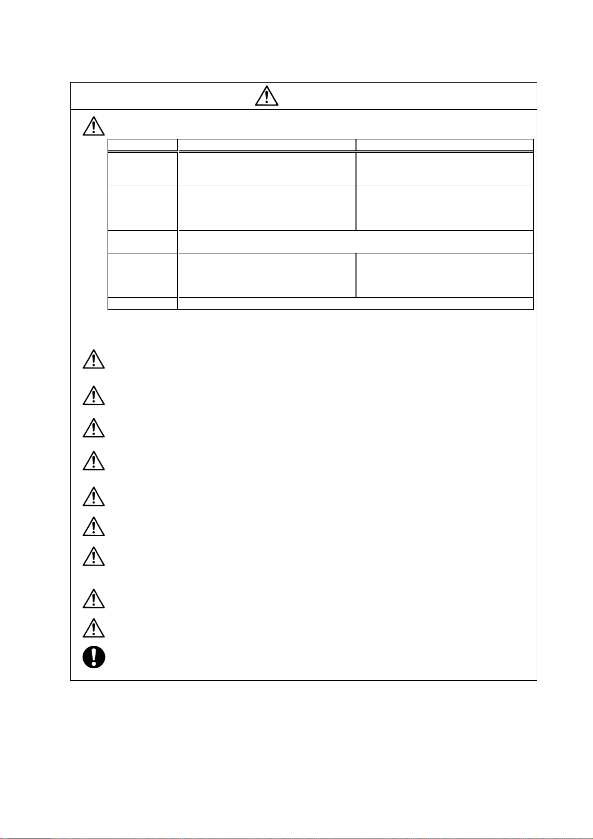
Store and use the units under the following environment conditions.
Environment
Ambient
temperature
Ambient
humidity
Atmosphere
Altitude
Vibration/impact
(Note 1) For details, confirm each unit or motor specifications in addition.
(Note 2) -15°C to 55°C for linear servomotor.
Operation: 0 to 55°C (with no freezing),
Storage / Transportation: -15°C to 70°C
Operation: 90%RH or less
(with no dew condensation)
Storage / Transportation: 90%RH or less
(with no dew condensation)
With no corrosive gas, inflammable gas, oil mist, dust or conductive fine particles
Operation/Storage: 1000 meters or less above
Transportation: 13000 meters or less above sea
Unit Motor
(with no freezing)
sea level,
level
According to each unit or motor specification
Operation: 0 to 40°C (with no freezing),
Storage: -15°C to 70°C
Operation: 80%RH or less
(with no dew condensation),
Storage: 90%RH or less
(with no dew condensation)
Indoors (no direct sunlight)
Operation: 1000 meters or less above sea level,
Storage: 10000 meters or less above sea level
(Note 2)
(with no freezing)
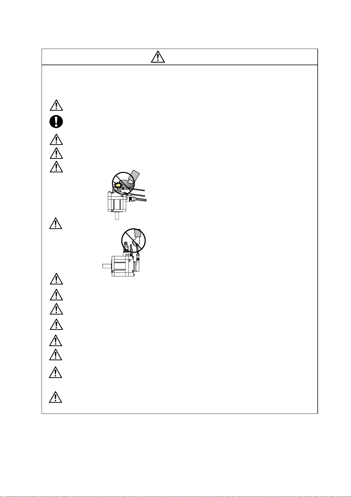
Securely fix the servomotor to the machine. Insufficient fixing could lead to the servomotor
slipping off during operation.
Always install the servomotor with reduction gear in the designated direction. Failure to do so
could lead to oil leaks.
Structure the rotary sections of the motor so that it can never be touched during operation.
Install a cover, etc., on the shaft.
When installing a coupling to a servomotor shaft end, do not apply an impact by hammering,
etc. The detector could be damaged.
Do not apply a load exceeding the tolerable load onto the servomotor shaft. The shaft could
break.
Store the motor in the package box.
When inserting the shaft into the built-in IPM motor, do not heat the rotor higher than 130°C.
The magnet could be demagnetized, and the specifications characteristics will not be
ensured.
Always use a nonmagnetic tool (explosion-proof beryllium copper alloy safety tool: NGK
Insulators, etc.) when installing the linear servomotor.
Always provide a mechanical stopper on the end of the linear servomotor's travel path.
If the unit has been stored for a long time, always check the operation before starting actual
operation. Please con t a ct t h e S e rv i c e C e n t er , S e rv i c e St a t i o n , S al e s O f f i c e o r d el a y e r.
Page 12
(2) Wiring
CAUTION
Correctly and securely perform the wiring. Failure to do so could lead to abnormal operation of
the motor.
Do not install a condensing capacitor, surge absorber or radio noise filter on the output side of
the drive unit.
Correctly connect the output side of the drive unit (terminals U, V, W). Failure to do so could
lead to abnormal operation of the motor.
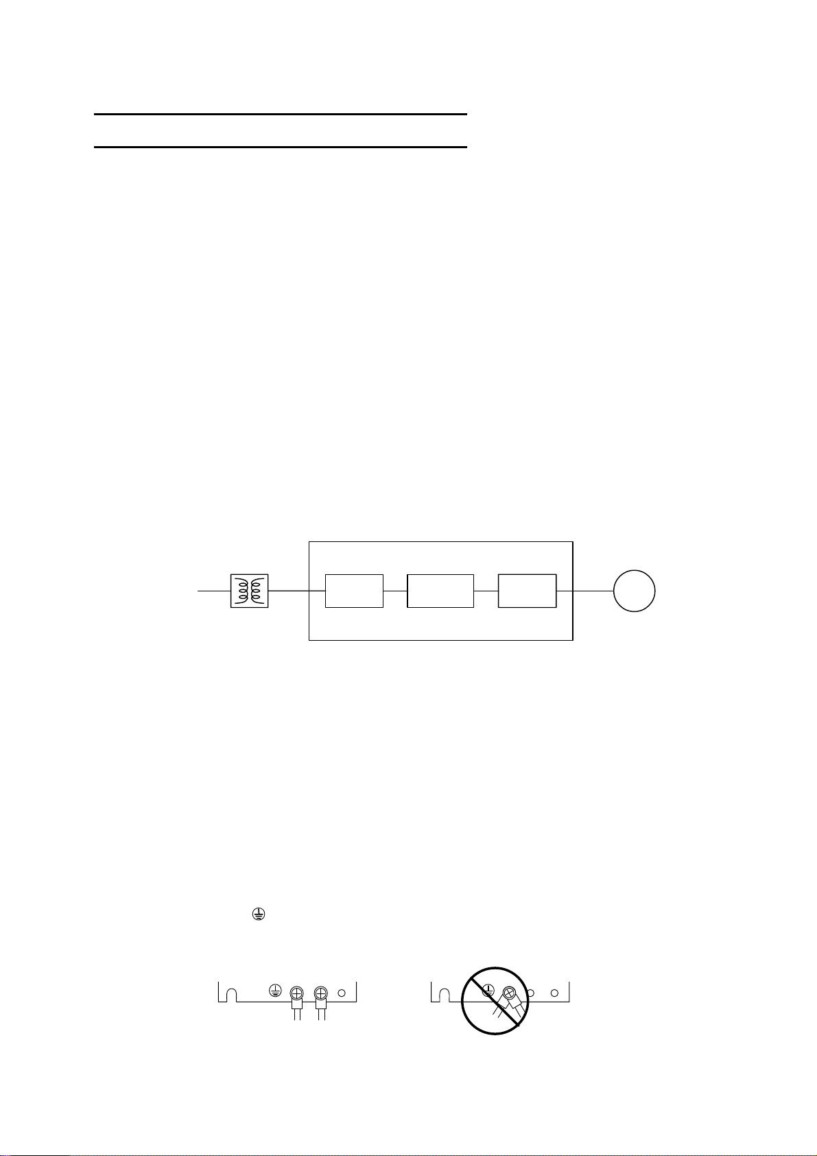
When using a power regenerative power supply unit, always install an AC reactor for each
power supply unit.
In the main circuit power supply side of the unit, always install an appropriate circuit protector
or contactor for each unit. Circui t protector or contactor cannot be shared by several units.
Always connect the motor to the drive unit's output terminals (U, V, W).
Do not directly connect a commercial power supply to the servomotor. Failure to observe this
could result in a fault.
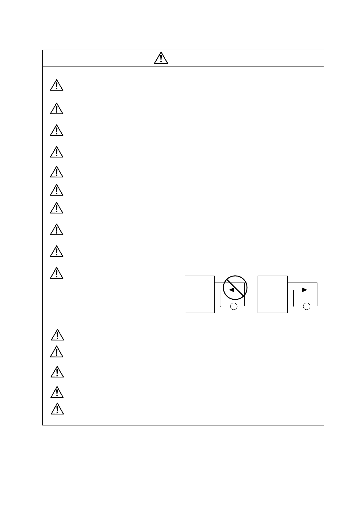
When using an inductive load such as a relay, always connect a diode as a noise measure
parallel to the load.
When using a capacitance load such as a lamp, always connect a protective resistor as a noise
measure serial to the load.
Do not reverse the direction of a diode
which connect to a DC relay for the
control output signals such as
Servodrive unit
COM
(24VDC)
Servodrive unit
COM
(24VDC)
contractor and motor brake output, etc.
to suppress a surge. Connecting it
backwards could cause the drive unit to
malfunction so that signals are not
Control output
signal
RA
Control output
signal
output, and emergency stop and other
safety circuits are inoperable.
RA
Do not connect/disconnect the cables connected between the units while the power is ON.
Securely tighten the cable connector fixing screw or fixing mechanism. An insecure fixing could
cause the cable to fall off while the power is ON.
When using a shielded cable instructed in the instruction manual, always ground the cable with
a cable clamp, etc.
Always separate the signals wires from the drive wire and power line.
Use wires and cables that have a wire diameter, heat resistance and flexibility that conforms to
the system.
Page 13
(3) Trial operation and adjustment
Check and adjust each program and parameter before starting operation. Failure to do so could
lead to unforeseen operation of the machine.
Do not make remarkable adjustments and changes of parameter as the operation could
become unstable.
The usable motor and unit combination is predetermined. Always check the models before
starting trial operation.
If the axis is unbalanced due to gravity, etc., balance the axis using a counterbalance, etc.
The linear servomotor does not have a stopping device such as magnetic brakes. Install a
stopping device on the machine side.
(4) Usage methods
In abnormal state, install an external emergency stop circuit so that the operation can be
stopped and power shut off immediately.
Turn the power OFF immediately if smoke, abnormal noise or odors are generated from the unit
or motor.
CAUTION
Do not disassemble or repair this product.
Never make modifications.
When an alarm occurs, the machine will start suddenly if an alarm reset (RST) is carried out
while an operation start signal (ST) is being input. Always confirm that the operation signal is
OFF before carrying out an alarm reset. Failure to do so could lead to accidents or injuries.
Reduce magnetic damage by installing a noise filter. The electronic devices used near the
unit could be affected by magnetic noise. Install a line noise filter, etc., if there is a risk of
magnetic noise.
Use the unit, motor and regenerative resistor with the designated combination. Failure to do so
could lead to fires or trouble.
The brake (magnetic brake) of the servomotor are for holding, and must not be used for normal
braking.
There may be cases when holding is not possible due to the magnetic brake's life, the machine
construction (when ball screw and servomotor are coupled via a timing belt, etc.) or the
magnetic brake’s failure. Install a stop device to ensure safety on the machine side.
After changing the programs/parameters or after maintenance and inspection, always test the
operation before starting actual operation.
Do not enter the movable range of the machine during automatic operation. Never place body
parts near or touch the spindle during rotation.
Follow the power supply specification conditions given in each specification for the power (input
voltage, input frequency, tolerable sudden power failure time, etc.).
Set all bits to "0" if they are indicated as not used or empty in the explanation on the bits.
Do not use the dynamic brakes except during the emergency stop. Continued use of the
dynamic brakes could result in brake damage.
If a circuit protector for the main circuit power supply is shared by several units, the circuit
protector may not activate when a short-circuit fault occurs in a small capacity unit. This is
dangerous, so never share the circuit protector.
Page 14
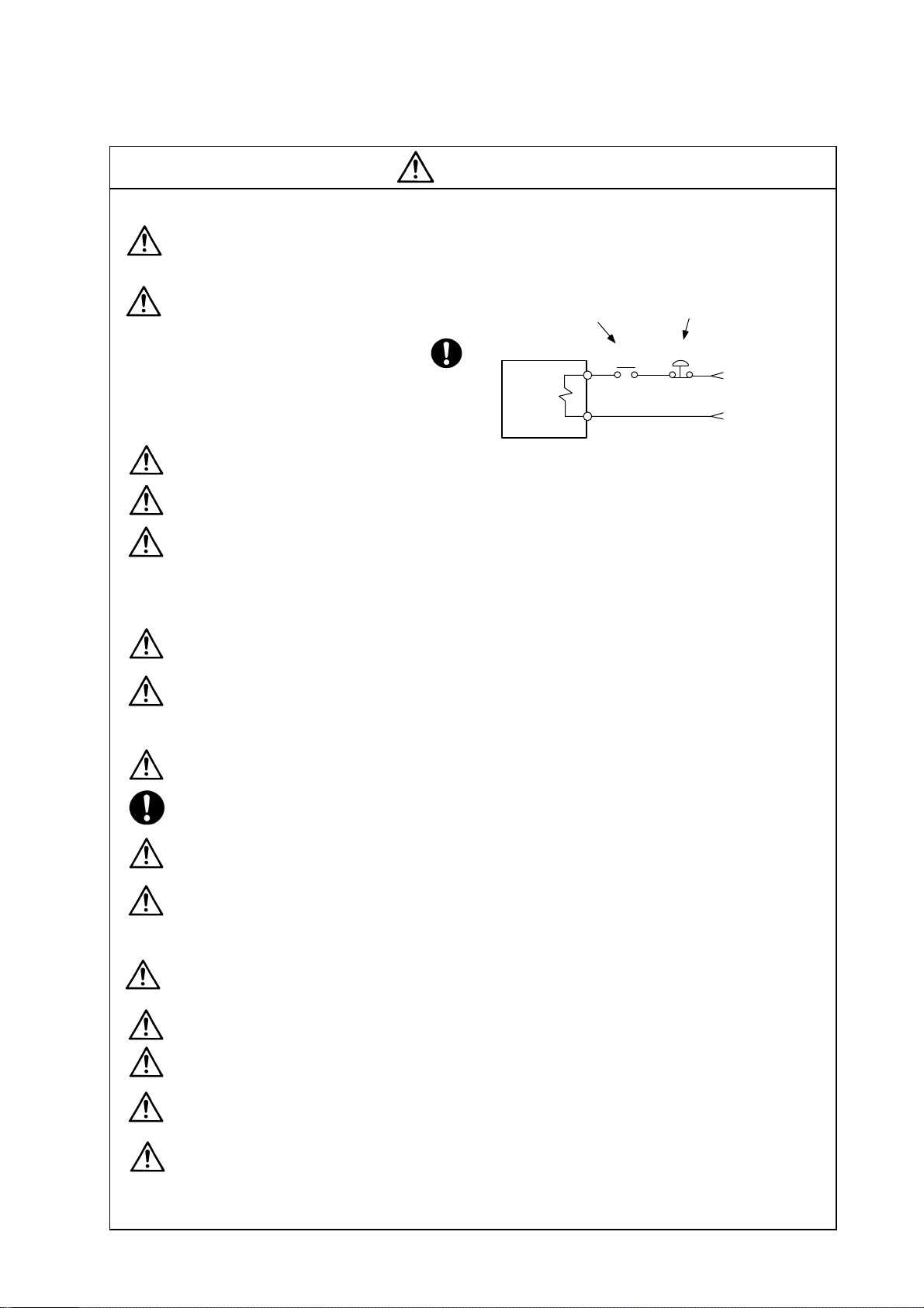
(5) Troubleshooting
If a hazardous situation is predicted during power failure or product trouble, use a servomotor
with magnetic brakes or install an external brake mechanism.
Use a double circuit configuration
that allows the operation circuit for
the magnetic brakes to be operated
even by the external emergency
stop signal.
CAUTION
Shut off with the servomotor
brake control output.
Servomotor
Magnetic
brake
Shut off with NC brake
control PLC output.
MBR
EMG
24VDC
Always turn the input power OFF when an alarm occurs.
If an alarm occurs, remove the cause, and secure the safety before resetting the alarm.
Never go near the machine after restoring the power after a power failure, as the machine
could start suddenly. (Design the machine so that personal safety can be ensured even if the
machine starts suddenly.)
(6) Maintenance, inspection and part replacement
Always backup the programs and parameters before starting maintenance or inspections.
The capacity of the electrolytic capacitor will drop over time due to self-discharging, etc. To
prevent secondary disasters due to failures, replacing this part every five years when used
under a normal environment is recommended. Contact the Service Center, Service Station,
Sales Office or delayer for repairs or part replacement.
Do not perform a megger test (insulation resistance measurement) during inspections.
If the battery low warning is issued, back up the machining programs, tool data and
parameters with an input/output unit, and then replace the battery.
Do not short circuit, charge, overheat, incinerate or disassemble the battery.
The heat radiating fin used in some units contains substitute Freon as the refrigerant.Take
care not to damage the heat radiating fin during maintenance and replacement work.
(7) Disposal
Do not dispose of this type of unit as general industrial waste. Always contact the Service
Center, Service Station, Sales Office or delayer for repairs or part replacement.
Do not disassemble the unit or motor.
Dispose of the battery according to local laws.
Always return the secondary side (magnet side) of the linear servomotor to the Service
Center or Service Station.
When incinerating optical communication cable, hydrogen fluoride gas or hydrogen chloride
gas which is corrosive and harmful may be generated. For disposal of optical communication
cable, request for specialized industrial waste disposal services that has incineration facility
for disposing hydrogen fluoride gas or hydrogen chloride gas.
Page 15
CAUTION
(8) Transportation
The unit and motor are precision parts and must be handled carefully.
According to a United Nations Advisory, the battery unit and battery must be transported
according to the rules set forth by the International Civil Aviation Organization (ICAO),
International Air Transportation Association (IATA), International Maritime Organization
(IMO), and United States Department of Transportation (DOT), etc.
(9) General precautions
The drawings given in this manual show the covers and safety partitions, etc., removed to provide a
clearer explanation. Always return the covers or partitions to their respective places before starting
operation, and always follow the instructions given in this manual.
Page 16

{ Treatment of waste {
The following two laws will apply when disposing of this product. Considerations must be made to each
law. The following laws are in effect in Japan. Thus, when using this product overseas, the local laws will
have a priority. If necessary, indicate or notify these laws to the final user of the product.
1. Requirements for "Law for Promotion of Effective Utilization of Resources"
(1) Recycle as much of this product as possible when finished with use.
(2) When recycling, often parts are sorted into steel scraps and electric parts, etc., and sold to scrap
contractors. Mitsubishi recommends sorting the product and selling the members to appropriate
contractors.
2. Requirements for "Law for Treatment of Waste and Cleaning"
(1) Mitsubishi recommends recycling and selling the product when no longer needed according to
item (1) above. The user should make an effort to reduce waste in this manner.
(2) When disposing a product that cannot be resold, it shall be treated as a waste product.
(3) The treatment of industrial waste must be commissioned to a licensed industrial waste treatment
contractor, and appropriate measures, including a manifest control, must be taken.
(4) Batteries correspond to "primary batteries", and must be disposed of according to local disposal
laws.
Page 17
Compliance to European EC Directives
1. European EC Directives
The European EC Directives were issued to unify Standards within the EU Community and to smooth
the distribution of products of which the safety is guaranteed. In the EU Community, the attachment of
a CE mark (CE marking) to the product being sold is mandatory to indicate that the basic safety
conditions of the Machine Directives (issued Jan. 1995), EMC Directives (issued Jan. 1996) and the
Low-voltage Directives (issued Jan. 1997) are satisfied. The machines and devices in which the servo
is assembled are a target for CE marking.
The servo is a component designed not to function as a single unit but to be used with a combination
of machines and devices. Thus, it is not subject to the EMC Directives, and instead the machines and
devices in which the servo is assembled are targeted.
This servo complies with the Standards related to the Low-voltage Directives in order to make CE
marking of the assembled machines and devices easier. The EMC INSTALLATION GUIDELINES (IB
(NA) 67303) which explain the servo amplifier installation method and control panel manufacturing
method, etc., has been prepared to make compliance to the EMC Directives easier. Contact
Mitsubishi or your dealer for more information.
2. Cautions of compliance
Use the standard servo amplifier and EN Standards compliance part (some standard models are
compliant) for the servomotor. In addition to the items described in this instruction manual, observe
the items described below.
(1) Configuration
Insulation
transformer
Control panel
Breaker
Magnetic
contactor
(MC)
Servo
amplifier
Motor
Use a type B (AC/DC detect abl e type) breaker
(2) Environment
The servo amplifier must be used within an environment having a Pollution Class 2 or less
(Pollution Class 1 or 2) as stipulated in the IEC60664. For this, install the servo amplifier in a
control panel having a structure (IP54) into which water, oil, carbon and dust cannot enter.
(3) Power supply
① The servo amplifier must be used with the overvoltage category II conditions stipulated in
IEC60664. For this, prepare a reinforced insulated transformer that is IEC or EN Standards
complying at the power input section.
② When supplying the control signal input/output power supply from an external source, use a 24
VDC power supply of which the input and output have been reinforced insulated.
(4) Installation
① To prevent electric shocks, always connect the servo amplifier protective earth (PE) terminal
(terminal with
mark) to the protective earth (PE) on the control panel.
② When connecting the earthing wire to the protective earth (PE) terminal, do not tighten the wire
terminals together. Always connect one wire to one terminal.
PE termi nal PE termi nal
Page 18
(5) Wiring
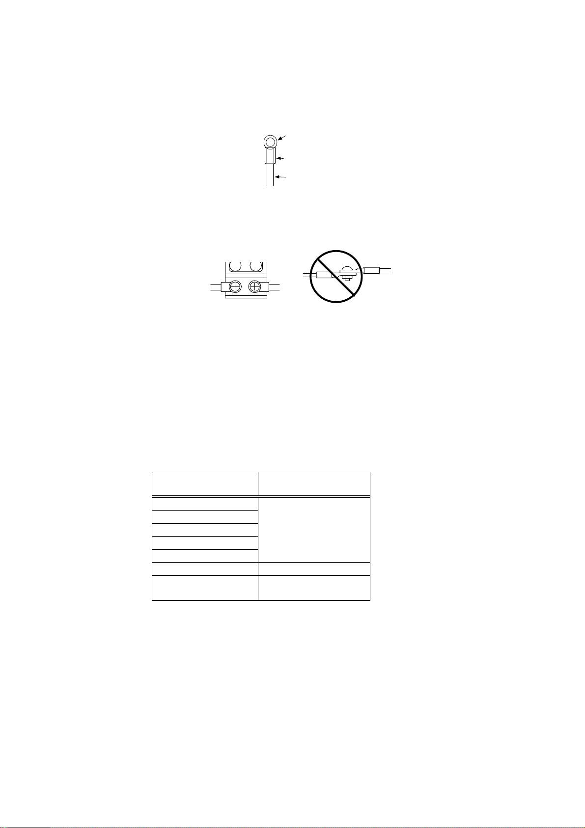
① Always use crimp terminals with insulation tubes so that the wires connected to the servo
amplifier terminal block do not contact the neighboring terminals.
Crimp terminal
Insulation tube
Wire
② Connect the HC-MF Series servomotor power lead to the servo amplifier using a fixed terminal
block. Do not connect the wires directly. (EN standards compliance parts of the HA-FF motor
have cannon plug specifications.)
(6) Peripheral devices
① Use a circuit protector and magnetic contactor that comply with the EN/IEC Standards
described in Chapter 7 Peripheral Devices.
② The wires sizes must follow the conditions below. When using other conditions, follow Table 5
of EN60204-1 Appendix C.
• Ambient temperature: 40°C
• Sheath: PVC (polyvinyl chloride)
• Install on wall without duct or conduit
(7) Servomotor
A servomotor that complies with the EN Standards as a standard, and an EN Standards
compatible part are available.
Motor series name
HCSeries
HCR Series
HA Series
HC-SF Series
HC-RF Series
HA-FF Series HA-FFC-UE
HC-MF Series
Refer to "Chapter 6 Dedicated Options" for the connectors and detector cables, and use the EN
Standards compatible parts.
(8) Enforcement of EMC test
The EMC test for a machine or device incorporating a servo amplifier must match the magnetism
compatibility (immunity and emission) standards in the state that the working environment and
electric device specifications are satisfied.
Refer to the EMC INSTALLATION GUIDELINES (IB (NA) 67303) for the EMC Directive measures
for the servo amplifier.
EN Standards
compatible part
Complies as a standard
HC-MF-UE
HC-MF-S15
Page 19
Instruction Manual for Compliance with UL/c-UL Standard
The instructions of UL/c-UL listed products are described in this manual.
The descriptions of this manual are conditions to meet the UL/c-UL
standard for the UL/c-UL listed products. To obtain the best performance,
be sure to read this manual carefully before use.
To ensure proper use, be sure to read specification manual carefully for
each product before use.
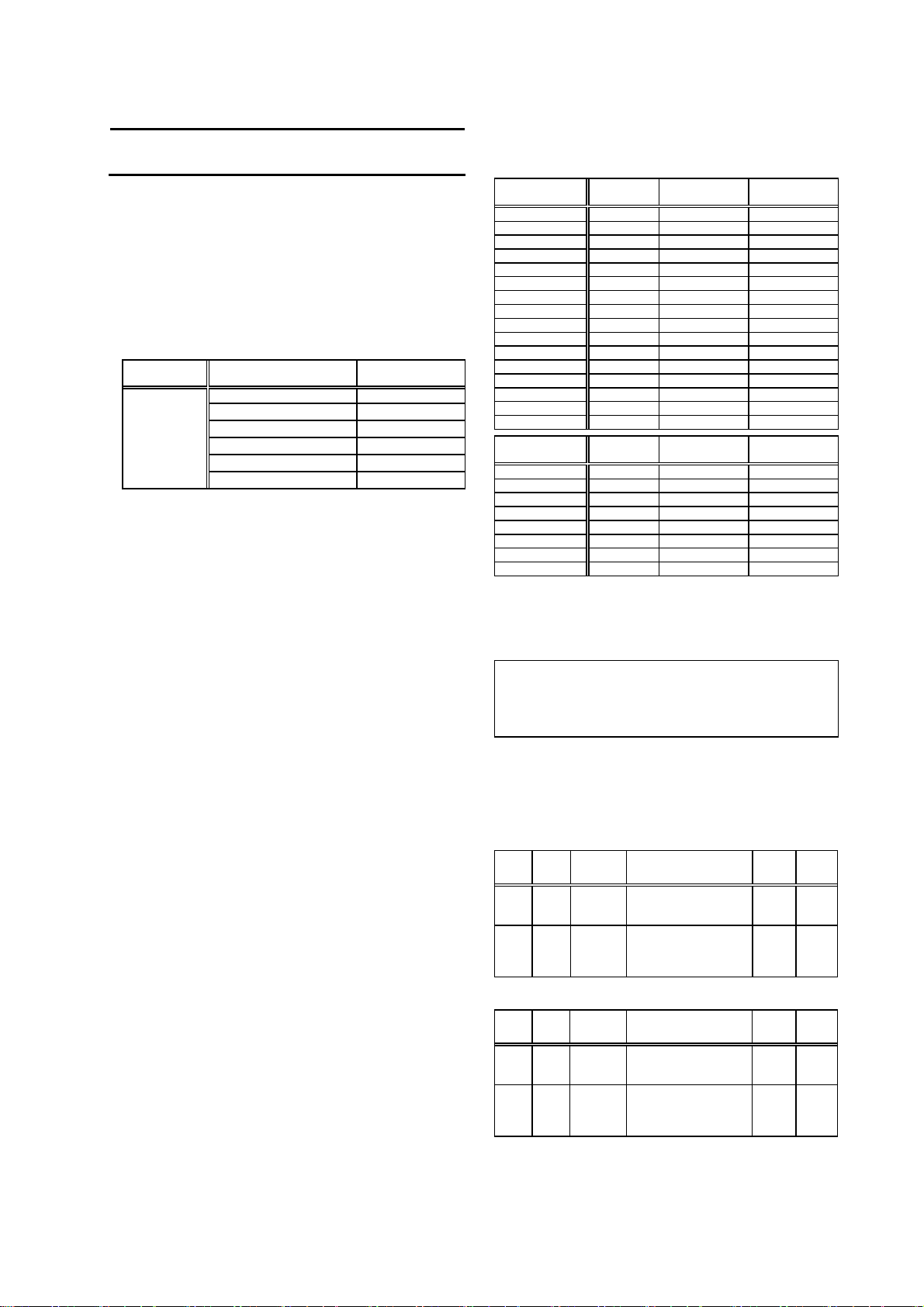
1. Operation surrounding air ambient temperature
The recognized operation ambient temperatures of each unit are as
shown in the table below. The recognized operation ambient
temperatures are the same as an original product specification for all
of the units.
Classification Unit name
AC servo/
spindle system
2. Notes for AC servo/spindle system
2-1 General Precaution
It takes 10 minutes to discharge the bus capacitor. (The capacitor
discharge time is one minute for MDS-B-SVJ2-01, 03, 04; two minutes
for MDS-B-SVJ2-06 and three minutes for MDS-B-SVJ2-07, 10, 20.)
When starting wiring or inspection, shut the power off and wait for
more than 15 minutes to avoid a hazard of electrical shock.
2-2 Installation
MDS-B-SVJ2, MDS-B-SPJ2 and MR-J2-CT Series have been
approved as the products which have been installed in the electrical
enclosure.
The minimum enclosure size is based on 150 percent of each
MDS-B-SVJ2, SPJ2 and MR-J2-CT Series combination. And also,
design the enclosure so that the ambient temperature in the enclosure
is 55°C (131°F) or less, refer to the specifications manual.
(MDS-B-SVJ2: BNP-B3937, MDS-B-SPJ2: BNP-B2164, MR-J2-CT:
BNP-B3944)
"The user must include the use of a 100 cfm fan spaced 4 in. above
the drive."
2-3 Short-circuit ratings
Suitable for use in a circuit capable of delivering not more than 100 kA
rms symmetrical amperes, 500 volts maximum.
(MDS-B-SVJ2, MDS-B-SPJ2 and MR-J2-CT Series)
operation ambient
temperature
Power supply unit 0~55°C
Servo drive unit 0~55°C
Spindle drive unit 0~55°C
Option unit 0~55°C
Battery unit 0~55°C
Servo motor, Spindle motor 0~40°C
2-4 Peripheral device
To comply with UL/c-UL Standard, use the peripheral devices which
conform to the corresponding standard.
- Fuses
Applicable
drive unit
UL Fuse
type
UL Voltage
rating, Vac
UL Current
rating, A
MDS-B-SVJ2-01 K5 250 10
MDS-B-SVJ2-03 K5 250 10
MDS-B-SVJ2-04 K5 250 15
MDS-B-SVJ2-06 K5 250 20
MDS-B-SVJ2-07 K5 250 20
MDS-B-SVJ2-10 K5 250 25
MDS-B-SVJ2-20 K5 250 40
MDS-B-SPJ2-02 K5 250 10
MDS-B-SPJ2-04 K5 250 15
MDS-B-SPJ2-075 K5 250 20
MDS-B-SPJ2-15 K5 250 40
MDS-B-SPJ2-22 K5 250 40
MDS-B-SPJ2-37 K5 250 60
MDS-B-SPJ2-55 K5 250 90
MDS-B-SPJ2-75 K5 250 125
MDS-B-SPJ2-110 K5 250 175
Applicable
drive unit
UL Fuse
type
UL Voltage
rating, Vac
UL Current
rating, A
MR-J2-10CT K5 250 10
MR-J2-20CT K5 250 10
MR-J2-40CT K5 250 15
MR-J2-60CT K5 250 20
MR-J2-70CT K5 250 20
MR-J2-100CT K5 250 25
MR-J2-200CT K5 250 40
MR-J2-350CT K5 250 70
- Circuit Breaker for of spindle motor Fan
Select the Circuit Breaker by doubling the spindle motor fan rated.
A rush current that is approximately double the rated current will
flow, when the fan is started
<Notice>
- For installation in United States, branch circuit protection must be
provided, in accordance with the National Electrical Code and any
applicable local codes.
- For installation in Canada, branch circuit protection must be
provided, in accordance with the Canada Electrical Code and any
applicable provincial codes.
2-5 Motor Over Load Protection
Servo drive unit MDS-B-SVJ2, MDS-B-SPJ2 and MR-J2-CT series
have each solid state motor over load protection.
current is the same as rated current.)
When adjusting the level of motor over load, set the parameter as
follows.
2-5-1 MDS-B-SVJ2 Series
Para-
Parameter
abbr.
Parameter
name
time
constant
detection
level
Setting procedure
Set the time constant for
overload detection.
(Unit: 1 second.)
Set the overload current
detection level with a
percentage (%) of the
meter
No.
SV021 OLT Overload
SV022 OLL Overload
stall rating.
2-5-2 MDS-B-SPJ2 Series
Para-
Parameter
abbr.
Parameter
name
meter
No.
SP063 OLT Overload
time
constant
SP064 OLL Overload
detection
level
Setting
procedure
Set the time constant for
overload detection.
(Unit: 1 second.)
Set the overload current
detection level with a
percentage (%) of the
rating.
2-5-3 MR-J2-CT Series
The overload current detection level is 150% of the rated current.
(The motor full load
Standard
60s 1~300s
150% 1~500
Standard
60s 0~1000
120% 0~200
setting
value
setting
value
Setting
range
%
Setting
range
s
%
Page 20
2-6 Flange of servo motor
Mount the servo motor on a flange which has the following size or
produces an equivalent or higher heat dissipation effect:
Flange size
(mm)
HC HC-RF HC-MF HA-FF HC-SF
150x150x6
250x250x6
250x250x12
300x300x12
- -
- -
0.5~
1.5kW
- -
300x300x20 2.0kW
Servo motor
under
100W
200W
1.0~
2.0kW
400W 400,600W
750W
- - -
under
100W
200,
300W
- -
-
-
0.5~
1.5kW
2.0kW
2-7 Field Wiring Reference Table for Input and Output
Use the UL-approved Round Crimping Terminals to wire the input and
output terminals of MDS-B-SVJ2, MDS-B-SPJ2 and MR-J2-CT Series.
Crimp the terminals with the crimping tool recommended by the
terminal manufacturer.
Following described crimping terminals and tools type is example of
Japan Solderless Terminal Mfg. Co., Ltd.
2-7-1 Servo Drive Unit (MDS-B-SVJ2 Series)
Capacity [kW]
0.1~0.7
D, C, P, N Note 1 M4 M4
Screw torque
[Ib in/ N m]
5.3/0.6 11/1.3 11/1.3
L11, L21 Note 1 M4 M4
Terminal
Screw Size
Screw torque
[lb in/ N m]
U, V, W,
L1,L2,L3
Screw torque
[lb in/ N m]
5.3/0.6 11/1.3 11/1.3
M4 M4 M4
11/1.3 11/1.3 11/1.3
Note1 Control circuit terminal block (MDS-B-SVJ2-01~07)
Terminal
D, C, P
L11, L21
Wire size
(AWG)
#14/75℃
Terminal bar model
Single-wire Double-wire
AI2.5-8BU
AI2.5-8BU-1000
AI-TWIN2x2.5-10BU
AI-TWIN2x2.5-13BU
Crimping terminals and tools type are example of Phoenix-contact
L11, L21 D, C, P
Capacity [kW] 1.0, 2.0 Capacity [kW] 1.0, 2.0
Wire Size (AWG)
/Temp rating
Note 2
Crimping
terminals type
Crimping tools
type
#14/60℃ #14/60℃
#14/75℃
V2-4
YNT-1614
Wire Size (AWG)
terminals type
Crimping tools
L1, L2, L3 U, V, W
Capacity [kW]
Wire size (AWG)
/Temp rating
Note 2
Crimping
terminals type
Crimping tools
type
Earth wire size
(AWG)
0.1~2.0
#14/60℃ #14/60℃
#14/75℃
R2-4
YHT-2210
#14/60℃ #14/60℃
#14/75℃
Capacity [kW]
Wire size (AWG)
terminals type
Crimping tools
Earth wire size
Note 2 75°C : Grade heat-resistant polyvinyl chloride insulated wires
(HIV)
Use copper wire only.
Above listed wire are for use in the electric cabinet on
machine or equipment.
1.0 2.0
/Temp rating
Note 2
Crimping
type
/Temp rating
Note 2
Crimping
type
(AWG)
Crimping
tools type
CRIMPFOX-
UD6
#14/75℃
R2-4
YHT-2210
0.1~2.0
#14/75℃
R2-4
YHT-2210
#14/75℃
2-7-2 Spindle Drive Unit (MDS-B-SPJ2)
Capacity [kW]
D, C, P, N Note1 M4 M4
Screw torque
[Ib in/ N m]
L11, L21 Note1 M4 M4
Terminal
screw size
Screw torque
[lb in/ N m]
U, V, W,
L1,L2,L3
Screw torque
[lb in/ N m]
Note1 Control circuit terminal block (MDS-B-SPJ2-02~075)
Terminal
D, C, P
L11, L21
Wire size
(AWG)
#14/75℃
Crimping terminals and tools type are example of Phoenix-contact.
L11, L21
Capacity [kW]
Wire size (AWG)
/Temp rating Note 2
Crimping terminals
type
Crimping tools type YNT-1614
D, C, P
Capacity [kW] 1.5
Wire Size (AWG)
/Temp rating Note 2
Crimping terminals
type
Crimping tools type YHT-2210
L1, L2, L3
Capacity [kW]
Wire Size (AWG)
/Temp rating Note 2
Crimping terminals
type
Crimping tools type YHT-2210 YHT-8S
Earth wire size
(AWG)
U, V, W
Capacity [kW]
Wire size (AWG)
/Temp rating Note 2
Crimping terminals
type
Crimping tools type YHT-2210 YHT-8S
Earth wire size
(AWG)
Note 2 75°C : Grade heat-resistant polyvinyl chloride insulated wires
(HIV)
Use copper wire only.
Above listed wire are for use in the electric cabinet on
machine or equipment.
0.2~0.75 1.5~3.7 5.5~11.0
5.3/0.6 10.4/1.2 10.4/1.2
5.3/0.6 10.4/1.2 17.4/2.0
M4 M4 M4
10.4/1.2 10.4/1.2 10.4/1.2
Terminal bar model
Single-wire Double-wire
AI2.5-8BU
AI2.5-8BU-1000
AI-TWIN2x2.5-10BU
AI-TWIN2x2.5-13BU
Crimping
tools type
CRIMPFOX-
UD6
1.5~11.0
#14/60℃
#14/75℃
V2-4
2.2~11.0
#14/60℃ #12/60℃
#14/75℃ #14/75℃
R2-4 5.5-S4
0.2~3.7
5.5 7.5 11.0
#14/60℃ #12/60℃ #10/60℃ #8/60℃
#14/75℃ #12/75℃ #10/75℃ #8/75℃
R2-4 5.5-S4 5.5-S4 TU8-4
#14/60℃ #12/60℃ #10/60℃ #8/60℃
#14/75℃ #12/75℃ #10/75℃ #8/75℃
0.2~3.7
5.5 7.5 11.0
#14/60℃ #12/60℃ #10/60℃ #8/60℃
#14/75℃ #12/75℃ #10/75℃ #8/75℃
R2-4 5.5-S4 5.5-S4 TU8-4
#14/60℃ #12/60℃ #10/60℃ #8/60℃
#14/75℃ #12/75℃ #10/75℃ #8/75℃
Page 21
2-7-3 Servo Drive Unit (MR-J2-CT Series)
Capacity [kW]
0.1~1.0
2.0 3.5
D, C, P, N Note 1 M4 M4
Screw torque
[Ib in/ N m]
5.3/0.6 11/1.3 11/1.3
L11, L21 Note 1 M4 M4
Terminal
screw size
Screw torque
[lb in/ N m]
U, V, W,
L1,L2,L3
Screw torque
[lb in/ N m]
5.3/0.6 11/1.3 11/1.3
M4 M4 M4
11/1.3 11/1.3 11/1.3
Note1 Control circuit terminal block (MR-J2-10~100)
Terminal
D, C, P
L11, L21
Wire size
(AWG)
#14/75℃
Terminal bar model
Single-wire Double-wire
AI2.5-8BU
AI2.5-8BU-1000
AI-TWIN2x2.5-10BU
AI-TWIN2x2.5-13BU
Crimping
tools type
CRIMPFOX-
UD6
Crimping terminals and tools type are example of Phoenix-contact
L11, L21 D, C, P
Capacity [kW] 2.0 , 3.5 Capacity [kW] 2.0 , 3.5
Wire size (AWG)
/Temp rating
Note 2
Crimping
terminals type
Crimping tools
type
#14/60℃ #14/60℃
#14/75℃
V2-4
YNT-1614
Wire size (AWG)
/Temp rating
Note 2
Crimping
terminals type
Crimping tools
type
#14/75℃
R2-4
YHT-2210
L1, L2, L3 U, V, W
Capacity [kW]
Wire size
(AWG)
/Temp rating
Note 2
Crimping
terminals type
Crimping tools
type
Earth wire size
(AWG)
0.1~2.0
#14/60℃ #10/60℃ #14/60℃ #10/60℃
#14/75℃ #10/75℃
R2-4 5.5-S4
#14/60℃ #12/60℃ #14/60℃ #12/60℃
#14/75℃ #12/75℃
3.5 Capacity [kW]
Wire size (AWG )
YHT-2210
Crimping tools
Earth wire size
/Temp rating
Note 2
Crimping
terminals type
type
(AWG)
0.1~2.0
#14/75℃ #10/75℃
R2-4 5.5-S4
YHT-2210
#14/75℃ #12/75℃
Note 2 75°C : Grade heat-resistant polyvinyl chloride insulated wires
(HIV)
Use copper wire only.
Above listed wire are for use in the electric cabinet on
machine or equipment.
2-8 Spindle Drive / Motor Combinations
Following combinations are the Standard combinations
Drive unit
MDS-B-SPJ2-02 0.2
MDS-B-SPJ2-04 0.4
MDS-SPJ2-075 0.75 0.75
MDS-B-SPJ2-15 1.5 1.5
MDS-B-SPJ2-22 2.2 2.2
MDS-B-SPJ2-37 3.7 3.7
MDS-B-SPJ2-55 5.5
MDS-B-SPJ2-75 5.5, 7.5
MDS-B-SPJ2-110 7.5, 11
Applicable spindle motor (kW)
SJ-P Series SJ-PF Series
3.5
Page 22
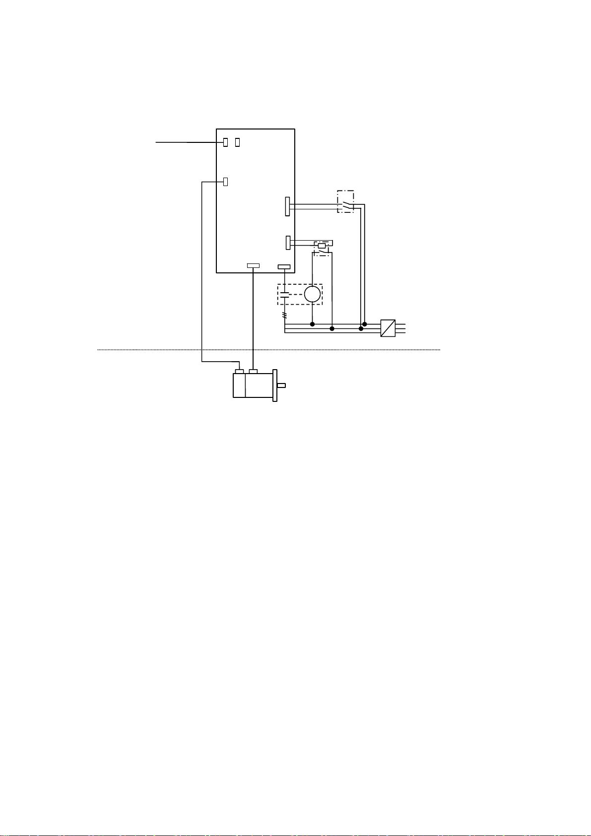
3. AC Servo/Spindle System Connection
From NC
Regarding the connection of
NC, see the NC manual book.
MDS-B-SVJ2
/MDS-B-SPJ2
/MR-J2-CT
CN1BCN1A
CN2
L11/L21
Note: It recommends installing.
CB
Enclosure Side
Machine Side
U,V,W
Contactor
Servo / Spindle Motor
Encoder
CN3
L1,L2,L3
MC
Relay
Refer to the following specification manuals.
MDS-B-SVJ2: BNP-B3937
MDS-B-SPJ2: BNP-B2164
MR-J2-CT: BNP-B3944
Fuse
or
Circuit Breaker
3 phases
200 to 230Vac
Input
Page 23
Compliance to Transportation Restrictions for Lithium Batteries
1. Restriction for packing
The United Nations Dangerous Goods Regulations "Article 12" became effective from 2003. When
transporting lithium batteries with means subject to the UN Regulations, such as by air transport,
measures corresponding to the Regulations must be taken. The UN Regulations classify the batteries
as dangerous goods (Class 9) or not dangerous goods according to the lithium content.
To ensure safety during transportation, lithium batteries (battery unit) directly exported from Mitsubishi
are packaged in a dedicated container (UN package) for which safety has been confirmed. When the
customer is transporting these products with means subject to the UN Regulations, such as air
transport, the shipper must follow the details explained in the section "1-2 Handling by user".
1-1 Target products
The following Mitsubishi NC products use lithium batteries. The UN Regulations classify the batteries
as dangerous goods (Class 9) or not dangerous goods according to the lithium content. If the batteries
subjected to hazardous materials are incorporated in a device and shipped, a dedicated packaging
(UN packaging) is not required. However, the item must be packed and shipped following the Packing
Instruction 912 specified in the IATA DGR (Dangerous Goods Regulation) book.
Also, all lithium battery products incorporated in a machinery or device must be fixed securely in
accordance with the Packing Instruction 900 and shipped with protection in a way as to prevent
damage or short-circuits.
(1) Products requiring dedicated packaging (Materials falling under Class 9)
Mitsubishi type
(Type for
arrangement)
MDS-A-BT-4
MDS-A-BT-6
MDS-A-BT-8
FCU6-BT4-D1
CR23500SE-CJ5
(Note1)
Battery type
ER6-B4-11 2.6g For servo
ER6-B6-11 3.9g For servo
ER6-B8-11 5.2g For servo
Combination of
ER6-B4D-11 and ER6
CR23500SE-CJ5 1.52g For NC(M500) Battery cell
(2) Products not requiring dedicated packaging (Materials not falling under Class 9)
Mitsubishi type
(Type for
arrangement)
MDS-A-BT-2
FCU6-BTBOX series
CR2032
(for built-in battery)
CR2450
(for built-in battery)
ER6, ER6V series
(for built-in battery)
A6BAT (MR-BAT)
Q6BAT
MR-J3BAT
(Note 1) When CR23500SE-CJ5 is incorporated in the unit, this battery is not subject to the regulation.
(Note 2) Dedicated packaging is required if the shipment exceeds 12 batteries/24 battery cells. Package the batteries so that
(Note 3) The battery units labeled as "FCUA-" instead of "MDS-A-" also use the same battery.
(Note 4)
this limit is not exceeded.
Always use the cell battery (A6BAT) in combination with the dedicated case (MDS-BTCASE). Maximum 8 (either 2, 4, 6
or 8) cell batteries (A6BAT) can be installed to the dedicated case (MDS-BTCASE).
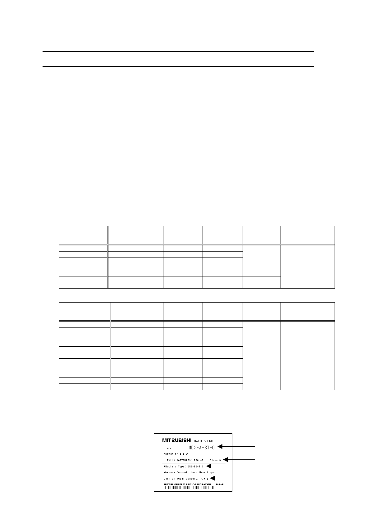
Example) Rating nameplate
for battery units
Battery type
ER6-B2-12 1.3g For servo
2CR5 1.96g For NC/ servo
CR2032 0.067g For NC
CR2450 0.173g For NC
ER6, ER6V 0.7g For NC/servo
ER17330V 0.48g For servo
Q6BAT 0.49g For NC
ER6V 0.65g For servo
Lithium metal
content
2.6g+0.65g For NC/ servo
Lithium metal
content
Application Battery class
Application Battery class
Outline dimension
drawing
Battery
Battery
Battery cell
For each outline
dimension drawing of
servo, refer to the
section “6-2 Battery
option”.
Outline dimension
drawing
For each outline
dimension drawing of
servo, refer to the
section “6-2 Battery
option”.
Mitsubishi type
Safety class
Battery manufacturer type
Lithium metal content
Page 24
1-2 Handling by user
The following technical opinion is solely Mitsubishi's opinion. The shipper must confirm the latest IATA
Dangerous Goods Regulations, IMDG Codes and laws and orders of the corresponding export
country. These should be checked by the company commissioned for the actual transportation.
IATA : International Air Transport Association
IMDG Code : A uniform international code for the transport of dangerous goods by seas
determined by IMO (International Maritime Organization).
■ When shipping isolated lithium battery products (Packing Instruction 903)
(1) Reshipping in Mitsubishi UN packaging
Mitsubishi packing applies the isolated battery's safety test and packaging specifications
complying with the UN Regulations (Packing Instruction 903).
The user only needs to add the following details before shipping. (Consult with the shipping
company for details.)
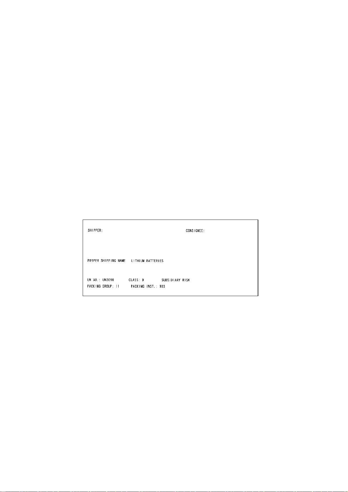
(a) Indication of container usage mark on exterior box (Label with following details
recorded.)
• Proper shipping name (Lithium batteries)
• UN NO. (UN3090 for isolated battery, UN3091 for battery incorporated in a device or
included)
• Shipper and consignee's address and name
(b) Preparation of shipping documents (Declaration of dangerous goods)
(Refer to "3. Example of hazardous goods declaration list" in this section.)
(2) When packaged by user
The user must follow UN Regulations when packing, preparing for shipping and preparing the
indications, etc.
(a) Packing a lithium battery falling under Class 9
• Consult with The Ship Equipment Inspection Society of Japan for details on packaging.
• Prepare for shipping as explained in "(1) Reshipping in Mitsubishi UN packaging".
The Ship Equipment Inspection Society of Japan
Headquarters Telephone: 03-3261-6611 Fax: 03-3261-6979
(b) Packing a lithium battery not falling under Class 9
• Cells and batteries are separated so as to prevent short circuits and are stored in a strong
outer packaging. (12 or less batteries, 24 or less cells.)
• Prepare for the certificates or test results showing compliance to battery safety test.
The safety test results have been obtained from the battery manufacturer. (Consult with
Mitsubishi when the safety test results are required.)
• Prepare for shipping as explained in "(1) Reshipping in Mitsubishi UN packaging".
Shipper information
Example of completing form
Consignee information
Page 25

■ When shipping lithium batteries upon incorporating in a machinery or device
(Packing Instruction 900)
Pack and prepare for shipping the item in accordance with the Packing Instruction 900 specified in
the IATA DGR (Dangerous Goods Regulation) book. (Securely fix the batteries that comply with the
UN Manual of Tests and Criteria to a machinery or device, and protect in a way as to prevent
damage or short-circuit.)
Note that all the lithium batteries provided by Mitsubishi have cleared the UN recommended safety
test; fixing the battery units or cable wirings securely to the machinery or device will be the user’s
responsibility.
Check with your shipping company for details on packing and transportation.
■ When shipping a device with lithium batteries incorporated (Packing Instruction 912)
A device incorporating lithium batteries does not require a dedicated packaging (UN packaging).
However, the item must be packed, prepared for shipping and labeled following the Packing
Instruction 912 specified in the IATA DGR (Dangerous Goods Regulation) book.
Check with your shipping company for details on packing and transportation.
The outline of the Packing Instruction 912 is as follows:
• All the items in the packing instructions for shipping the isolated lithium battery products
(Packing Instruction 903) must be satisfied, except for the items related to container,
short-circuit, and fixation.
• A device incorporating lithium batteries has to be stored in a strong water-proofed outer
packaging.
• To prevent an accidental movement during shipment, securely store the item in an outer
packaging.
• Lithium content per device should be not more than 12g for cell and 500g for battery.
• Lithium battery mass per device should be not more than 5kg.
1-3 Reference
Refer to the following materials for details on the regulations and responses.
Guidelines regarding transportation of lithium batteries and lithium ion batteries (Edition 2)
• • • • • Battery Association of Japan
Page 26

2. Issuing domestic law of the United State for primary lithium battery
transportation
Federal Aviation Administration (FAA) and Research and Special Programs Administration (RSPA)
announced an additional regulation (interim final rule) for the primary lithium batteries transportation
restrictions item in "Federal Register" on Dec.15 2004. This regulation became effective from Dec.29,
2004.
This law is a domestic law of the United States, however if also applies to the domestic flight and
international flight departing from or arriving in the United States. Therefore, when transporting lithium
batteries to the United State, or within the United State, the shipper must take measures required to
transport lithium batteries.
Refer to the Federal Register and the code of Federal Regulation ("2-4 Reference”) for details.
2-1 Outline of regulation
(1) Transporting primary lithium battery by passenger aircraft is forbidden.
• Excluding primary lithium battery for personal use in a carry-on or checked luggage
(Lithium metal content should be not more than 5g for cell and 25g for battery. For details on
the lithium metal content, refer to "1-1 Target products".)
(2) When transporting primary lithium battery by cargo aircraft, indicate that transportation by
passenger aircraft is forbidden on the exterior box.
2-2 Target products
All NC products for which the lithium batteries are used are subject to the regulation.
(Refer to the table "1-1 Target products".)
2-3 Handling by user
The "2-1 Outline of regulation" described above is solely Mitsubishi's opinion. The shipper must
confirm orders of "2-4 Reference" described below for transportation method corresponding the
regulation. Actually, these should be checked by the company commissioned for the actual lithium
buttery transportation.
(1) Indication of exterior box
When transporting primary lithium battery by cargo aircraft, indicate that transportation by
passenger aircraft is forbidden on the exterior box.
Display example
FORBIDDEN FOR TRANSPORT ABOARD PASSENGER AIRCRAFT.
• The character color must be displayed with contrast. (black characters against white
background, black characters against yellow background, etc.)
• The height (size) of characters to be displayed is prescribed depending on the packaging mass.
When the total mass is over 30kg: at least 12mm
When the total mass is less than 30kg: at least 6mm
PRIMARY LITHIUM BATTERIES
2-4 Reference
(1) Federal Register (Docket No. RSPA-2004-19884 (HM-224E) ) PDF format
http://www.regulations.gov/fredpdfs/05-11765.pdf
(2) 49CFR (Code of Federal Regulation, Title49) (173.185 Lithium batteries and cells.)
http://www.access.gpo.gov/nara/cfr/waisidx_00/49cfr173_00.html
(3) DOT regulation body (Department of Transportation)
http://hazmat.dot.gov/regs/rules/final/69fr/docs/69fr-75207.pdf
Page 27
3. Example of hazardous goods declaration list
This section describes a general example of the hazardous goods declaration list. For details,
please inquire each transportation company.
This will be applied only to the batteries described in "1. Restriction for Packing".
(1) Outline of hazard
Principal hazard and effect
Specific hazard
Environmental effect
Possible state of emergency
(2) First-aid measure
Inhalation
Skin contact
Eye contact
Ingestion
(3) Fire-fighting measure
Appropriate fire-extinguisher
Special fire-fighting measure
Protectors against fire
(4) Measure for leakage
Environmental precaution
How to remove
(5) Handling and storage
Cautions for safety
handling
Handling
Appropriate storage
Storage
condition
Material to avoid
(6) Physical/chemical properties
Physical form
Shape
Smell
Appearance
pH
Boiling point/Boiling
range,
Melting point,
Decomposition
temperature,
Flash point
Not found.
As the chemical substance is stored in a sealed metal container, the battery itself is
not hazardous. But when the internal lithium metal attaches to human skin, it
causes a chemical skin burn. As a reaction of lithium with water, it may ignite or
forms flammable hydrogen gas.
Not found.
Damages or short-circuits may occur due to external mechanical or electrical
pressures.
If a person inhales the vapor of the substance due to the battery damage, move the
person immediately to fresh air. If the person feels sick, consult a doctor
immediately.
If the content of the battery attaches to human skin, wash off immediately with
water and soap. If skin irritation persists, consult a doctor.
In case of contact with eyes due to the battery damage, rinse immediately with a
plenty of water for at least 15 minutes and then consult a doctor.
If swallowed, consult a doctor immediately.
Dry sand, dry chemical, graphite powder or carbon dioxide gas
Keep the battery away from the fireplace to prevent fire spreading.
Fire-protection gloves, eye/face protector (face mask), body/skin protective cloth
Dispose of them immediately because strong odors are produced when left for a
long time.
Get them absorbed into dry sand and then collect the sand in an empty container.
Do not peel the external tube or damage it.
Do not dispose of the battery in fire or expose it to heat.
Do not immerse the battery in water or get it wet.
Do not throw the battery.
Do not disassemble, modify or transform the battery.
Do not short-circuit the battery.
Avoid direct sunlight, high temperature and high humidity.
(Recommended temp. range: +5 to +35 oC, humidity: 70%RH or less)
Flammable or conductive material (Metal: may cause a short-circuit)
Solid
Cylinder type
Odorless
Not applicable (insoluble)
No information
Page 28

(7) Stability and reactivity
Stability
Condition to avoid
Hazardous decomposition
products
(8) Toxicological information
As the chemical substance is stored in a sealed metal container, the battery has no harmfulness.
Just for reference, the table below describes the main substance of the battery.
(Lithium metal)
Acute toxicity
Local effect
(9) Ecological information
Mobility,
Persistence/Decomposability,
Bio-accumulation potential,
Ecological toxicity
(10) Caution for disposal
Dispose of the battery following local laws or regulations.
Pack the battery properly to prevent a short-circuit and avoid contact with water.
Stable under normal handling condition.
Do not mix multiple batteries with their terminals uninsulated. This may cause a
short-circuit, resulting in heating, bursting or ignition.
Irritative or toxic gas is emitted in the case of fire.
No information
Corrosive action in case of skin contact
Not found.
Page 29
Compliance with Restrictions in China
1. Compliance with China CCC certification system
1-1 Outline of China CCC certification system
The Safety Certification enforced in China included the "CCIB Certification (certification system based
on the "Law of the People’s Republic of China on Import and Export Commodity Inspection" and
"Regulations on Implementation of the Import Commodities Subject to the Safety and Quality
Licensing System" enforced by the State Administration of Import and Export Commodity Inspection
(SACI) on import/export commodities, and the "CCEE Certification" (certification system based on
"Product Quality Certification Management Ordinance" set forth by the China Commission for
Conformity Certification of Electrical Equipment (CCEE) on commodities distributed through China.
CCIB Certification and CCEE Certification were merged when China joined WTO (November 2001),
and were replaced by the "China Compulsory Product Certification" (hereinafter, CCC Certification)
monitored by the State General Administration of Quality Supervision, Inspection and Quarantine
(AQSIQ) of the People's Republic of China.
The CCC Certification system was partially enforced from May 2002, and was fully enforced from May
2003. Target commodities which do not have CCC Certification cannot be imported to China or sold in
China. (Indication of the CCIB or CCEE mark has been eliminated from May 1, 2003.)
CCIB : China Commodity Inspection Bureau
CCEE : China Commission for Conformity Certification of Electrical Equipment
CCC : China Compulsory Certification
1-2 First catalogue of products subject to compulsory product certification
The First Catalogue of Products subject to Compulsory Product Certification, covering 132 items (19
categories) based on the CCIB products (104 items), CCEE products (107 items) and CEMC products
(Compulsory EMC Certification products) was designated on December 3, 2001.
Class Product catalogue Class Product catalogue
1 Electric Wires and Cables (5 items) 5 Electric tools (16 items)
2 Switches, Installation protective and connection devices (6 items) 6 Welding machines (15 items)
Low-voltage Electrical Apparatus (9 items) Compulsory Certification
3
Circuit-breakers (including RCCB, RCBO, MCB) 8 Audio and video equipment (16 items)
Low-voltage switchers
(disconnectors, switch-disconnectors, and
fuse-combination devices.
Other protective equipment for circuits
(Current limiting devices, circuits protective
devices, over current protective devices,
thermal protectors, over load relays,
low-voltage electromechanical contactors and
motor starters)
Relays (36V < Voltage ≤ 1000V)
Other switches
(Switches for appliances, vacuum switches,
pressure switches, proximity switches, foot
switches, thermal sensitive switches, hydraulic
switches, push-button switches, position limit
switches, micro-gap switches, temperature
sensitive switches, travel switches,
change-over switches, auto-change-over
switches, knife switches)
Other devices
(contactors, motor starters, indicator lights,
auxiliary contact assemblies, master
controllers, A.C. Semiconductor motor
controllers and starters)
Earth leakage protectors
Fuses
Low-voltage switchgear CNCA-01C-010:2001
4 Small power motors (1 item)
(Note)
Regulations
CNCA -01C -011: 2001
(Switch and Control
Equipment)
CNCA -01C -012: 2001
(Installation Protective
Equipment)
(Low-voltage
switchgear)
CNCA-01C-013:2001
(Small power motors)
(Note) When the servomotor or the spindle motor of which output is 1.1kW or less (at 1500 r/min) is used, NC could have been
considered as a small power motor. However, CQC (China Quality Certification Center) judged it is not.
7 Household and similar
electrical appliances
9 Information technology
equipment
10 Lighting apparatus (2 items)
11 Telecommunication terminal
equipment
12 Motor vehicles and Safety
Parts
13 Tyres (4 items)
14 Safety Glasses (3 items)
15 Agricultural Machinery (1 item)
16 Latex Products (1 item)
17 Medical Devices (7 items)
18 Fire Fighting Equipment (3 items)
19 Detectors for Intruder Alarm
Systems
(18 items)
(12 items)
(9 items)
(4 items)
(1 item)
Page 30

1-3 Precautions for shipping products
As indicated in 1-2, NC products are not included in the First Catalogue of Products subject to
Compulsory Product Certification. However, the Customs Officer in China may judge that the product
is subject to CCC Certification just based on the HS Code.
NC cannot be imported if its HS code is used for the product subject to CCC Certification. Thus, the
importer must apply for a "Certification of Exemption" with CNCA.
Exemption for details on applying for an exemption.
(Note 1) The First Catalogue of Products subject to Compulsory Product Certification (Target HS
Codes) can be confirmed at http://www.cqc.com.cn/Center/html/60gonggao.htm.
(Note 2) HS Code: Internationally unified code (up to 6 digits) assigned to each product and used for
customs.
(Note 3) CNCA: Certification and Accreditation Administration of People's Republic of China
(Management and monitoring of certification duties)
Note 2
Note 3
Refer to 1-4 Application for
Page 31

1-4 Application for exemption
Following "Announcement 8" issued by the Certification and Accreditation Administration of the
People's Republic of China (CNCA) in May 2002, a range of products for which application for CCC
Certification is not required or which are exempt from CCC marking has been approved for special
circumstances in production, export and management activities.
An application must be submitted together with materials which prove that the corresponding product
complies with the exemption conditions. Upon approval, a "Certification of Exemption" shall be issued.
<Range of products for which application is exempt>
Range of products not
requiring application
Range of products for
which application is
exempted
The following documents must be prepared to apply for an exemption of the "Import Commodity
Safety and Quality License" and "CCC Certification".
(1) Formal Application
(a) Relevant introduction and description of the company.
(b) The characteristics of the products to be exempted.
(c) The reason for exemption and its evidence (ex. customs handbook).
(d) The name, trademark, quantity, model and specification of the products to be exempted.
(Attach a detail listing of these items for a large quantity of products. When importing
materials for processing and repair equipments, submit a list of the importing materials for
each month and repair equipments.)
(e) Guarantee for the safety of the products; self-declaration to be responsible for the safety
during the manufacturing and use.
(f) To be responsible for the authenticity and legitimacy of the submitted documents.
Commitment to assist CNCA to investigate on the authenticity of the documents (When
CNCA finds it necessary to investigate on the authenticity of the documents.)
(2) Business license of the company (Copy)
(3) Product compliance declaration
Indicate which standard’s requirements the products comply with or submit a test report (Copy is
acceptable. The report can be prepared in a manufacturer’s laboratory either at home or
overseas.)
(4) Import license (Only if an import license is needed for this product. Copy is acceptable.)
(5) Quota certificate (Only if a quota certificate is needed for this product. Copy is acceptable.)
(6) Commercial contract (Copy is acceptable.)
(7) If one of item (4), (5) or (6) cannot be provided, alternative documents, such as bill of
lading, the invoice, and other evidential documents must be submitted.
(a) Items brought into China for the personal use by the foreign embassies, consulates, business
agencies and visitors
(Excluding products purchased from Service Company for Exporters)
(b) Products presented on a government-to-government basis, presents
(c) Exhibition products (products not for sale)
(d) Special purpose products (e.g., for military use)
Products not requiring application for CCC Certification are not required to be CCC marked or
certified.
(e) Products imported or manufactured for research and development and testing purposes
(f) Products shipped into China for integration into other equipment destined for 100% re-export to a
destination outside of China
(g) Products for 100% export according to a foreign trade contract (Excluding when selling partially
in China or re-importing into China for sales)
(h) Components used for the evaluation of an imported product line
(i) The products imported or manufactured for the service (service and repairs) to the end-user. Or
the spare parts for the service (service and repairs) of discontinued products.
(j) Products imported or manufactured for research and development, testing or measurements
(k) Other special situations
Page 32

1-5 Mitsubishi NC product subject to/not subject to CCC certification
The state whether or not Mitsubishi NC products are subject to the CCC Certification is indicated
below, based on the "First Catalogue of Products subject to Compulsory Product Certification" issued
by the State General Administration of Quality Supervision, Inspection and Quarantine (AQSIQ) of the
People's Republic of China and the Certification and Accreditation Administration of the People's
Republic of China (CNCA) on July 1, 2002.
Model China HS Code (Note 1)
Power supply unit
Servo/spindle drive unit
Servo/spindle
NC – Not subject to CCC Certification
Display unit – Not subject to CCC Certification
85044090
85371010
85015100
85015200
(Note 1) The China HS Code is determined by the customs officer when importing to China. The
above HS Codes are set based on the HS Codes used normally when exporting from
Japan.
(Note 2) Reference IEC Standards are used as the actual IEC Standards may not match the GB
Standards in part depending on the model.
Whether or not the NC products are subject to CCC Certification was judged based on the following
five items.
(a) Announcement 33 (Issued by AQSIQ and CNCA in December 2001)
(b) HS Codes for the products subject to CCC Certification (Export Customs Codes)
* HS Codes are supplementary materials used to determine the applicable range. The applicable
range may not be determined only by these HS Codes.
(c) GB Standards (This is based on the IEC Conformity, so check the IEC. Note that some parts are
deviated.)
(d) Enforcement regulations, and products specified in applicable range of applicable standards
within
(e) "Products Excluded from Compulsory Certification Catalogue" (Issued by CNCA, November
2003)
Judgment on whether or not subject
to CCC Certification
Not subject to CCC Certification
Not subject to CCC Certification
Reference
• Outline of China's New Certification System (CCC Mark for Electric Products), Japan Electrical
Manufacturers' Association
• Outline of China's New Certification System (CCC Mark for Electric Products) and Electric
Control Equipment, Nippon Electric Control Equipment Industries Association
Page 33

2. Response to the China environment restrictions
2-1 Outline of the law on the pollution prevention and control for electronic information
products
Ministry of Information Industry (information industry ministry) issued this law on Feb.28, 2006 (Note)
(effective from Mar.1, 2007.) in order to protect the environment and the health of the people with
restricting and reducing the environmental pollution caused by the electronic information product
wastes. The restrictions are applied to containing lead (Pb), hydrargyrum (Hg), cadmium (Cd),
hexavalent chromium (Cr (VI)), polybrominated biphenyl (PBB) and polybrominated diphenyl ether
(PBDE) in two stages.
(Note) For the details, refer to the following.
http://www.mii.gov.cn/art/2006/03/02/art_524_7343.html
(1) First stage: Requirement of indicating contained substance
The producer and importer of the electronic information product are required to indicate the
hazardous substance. The concrete categories of the products belonging in the following eleven
main categories are described as subjected product list (electronic information product category
note).
• Radar device • Communication device • Radio/TV device industry product
• Computer product • Consumer-electronics device • Electronic measuring apparatus
• Electronics industry dedicated device • Electronic parts • Electronics device
• Electronics application product • Electronics dedicated material
(2) Second stage: Suppressing the amount of contained substances and compulsory CCC
Certification
The product listed in the “Electronic information product pollution priority control list” cannot be
sold in China unless it conforms to the Compulsory Product Certification System (CCC
Certification) and its cadmium usage is suppressed to 0.01w% and other substances usage less
than 0.1w%. Note that the timing when this is effective is unmentioned.
2-2 Response to the drive product for Mitsubishi NC
The drive product for NC has no items falling under the subjected product list (electronic information
product category note). However, for use with the drive product included in the subjected product or
for treating the product properly, information based on the law on the pollution prevention and control
for electronic information products” are described in the section “Appendix 9-2-3” for reference.
2-3 Indication based on “Pollution suppression marking request for electronic
information product”
(1) Electronic information product pollution suppression marking
This marking indicates the environmental protection expiration date
applied to the electronic information products sold in China according to
the law on the pollution prevention and control for electronic information
products issued on Feb.28, 2006. As long as you keep safety for this
product and follow the precautions for use, there are no serious effects on
the environment pollution, human body or property within its term
reckoned from the manufacturing date.
Note: This symbol mark is
for China only.
(Note) Equate the environmental protection expiration date of
consumables, such as enclosed battery and cooling fan, with the
product life. When disposing the product after using it properly,
obey each local laws and restrictions for collecting and recycling of
the electronic information product.
Page 34

(2) The names of contained six hazardous substances and the parts containing them
The names of six substances contained in this product and the parts containing them are shown
below.
Toxic/hazardous substance or element
Parts name
Drive unit
Servo motor/spindle motor
Dedicated options (cable/connector)
Dedicated Options
(detector/AC reactor)
Dedicated Options (battery)
○: This mark means that toxic/hazardous substance content in all homogeneous materials of corresponding parts does not
exceed the standard specified in the standard of SJ/T11363-2006.
×: This mark means that toxic/hazardous substance content in the homogeneous materials of corresponding parts exceeds the
standard specified in the standard of SJ/T11363-2006.
Lead
(Pb)
× ○ ○ ○ ○ ○
× ○ ○ ○ ○ ○
× ○ ○ × ○ ○
× ○ ○ × ○ ○
× ○ ○ ○ ○ ○
Hydrargyrum
(Hg)
Cadmium
(Cd)
Hexavalent
chromium
(Cr(VI))
(PBB) (PBDE)
Page 35

Contents
Chapter 1 Preface
1-1 Inspection at purchase ............................................................................................................1-2
1-1-1 Package contents............................................................................................................1-2
1-1-2 Explanation of types ........................................................................................................1-2
1-2 Explanation of each part..........................................................................................................1-7
1-2-1 Explanation of each servo amplifier part .........................................................................1-7
Chapter 2 Wiring and Connection
2-1 System connection diagram....................................................................................................2-3
2-2 Servo amplifier main circuit terminal block, control circuit terminal block...............................2-4
2-2-1 Main circuit terminal block, control circuit terminal block signal layout ...........................2-4
2-2-2 Names and application of main circuit terminal block and control circuit terminal
block signals..2-5
2-2-3 How to use the control circuit terminal block (MDS-B-SVJ2-01~07)...............................2-6
2-3 NC and servo amplifier connection .........................................................................................2-9
2-4 Motor and detector connection..............................................................................................2-10
2-4-1 Connection of HC52, HC53, HC102* ............................................................................2-10
2-4-2 Connection of HC102, HC103, HC152*, HC152, HC153.............................................. 2-11
2-4-3 Connection of HC202*, HC202, HC203*, HC352* ........................................................ 2-12
2-4-4 Connection of HC103R, HC153R, HC203R..................................................................2-13
2-4-5 Connection of HA053N, HA13N ....................................................................................2-14
2-4-6 Connection of HA23N, HA33N ......................................................................................2-14
2-4-7 Connection of HA40N,HA43N.......................................................................................2-15
2-4-8 Connection of HA80N, HA83N ......................................................................................2-15
2-4-9 Connection of HA100N, HA103N*, HA200N*................................................................2-16
2-4-10 Connection of HC-SF52, HC-SF53, HC-SF102, HC-SF103.......................................2-17
2-4-11 Connection of HC-SF152, HC-SF153..........................................................................2-17
2-4-12 Connection of HC-SF202, HC-SF203, HC-SF352, HC-SF353................................... 2-18
2-4-13 Connection of HC-RF103, HC-RF153, HC-RF203 .....................................................2-18
2-4-14 Connection of HA-FF Series........................................................................................2-19
2-4-15 Connection of HA-FF□C-UE Series ...........................................................................2-19
2-4-16 Connection of HC-MF(-UE) Series..............................................................................2-20
2-4-17 Connection of HC-MF□-S15 Series ...........................................................................2-20
2-5 Connection of power supply..................................................................................................2-21
2-5-1 Example of connection when using converter unit........................................................2-21
2-5-2 Example of connection when controlling the contactor with the MDS-B-SVJ2.............2-23
2-6 Connection of regenerative resistor ......................................................................................2-24
2-6-1 Connection of standard built-in regenerative resistor....................................................2-24
2-6-2 Connection of external option regenerative resistor......................................................2-25
2-6-3 Connection of external option regeneration resistance unit..........................................2-26
2-7 Wiring of contactors...............................................................................................................2-27
2-7-1 Contactor power ON sequences ................................................................................... 2-28
2-7-2 Contactor shutoff sequences......................................................................................... 2-28
2-7-3 Contactor control signal (MC) output circuit ..................................................................2-29
2-8 Wiring of motor brake ............................................................................................................2-30
2-8-1 Motor brake release sequence......................................................................................2-30
2-8-2 Control during servo OFF commands ...........................................................................2-30
2-8-3 Operation sequences when an emergency stop occurs ............................................... 2-30
2-8-4 Motor brake control signal (MBR) output circuit ............................................................ 2-31
2-9 Wiring of external emergency stop........................................................................................2-32
2-9-1 External emergency stop setting...................................................................................2-32
2-9-2 External emergency stop operation sequences ............................................................ 2-33
2-9-3 External emergency stop signal (EMGX) input circuit...................................................2-34
I
Page 36

Chapter 3 Installation
3-1 Installation of servo amplifier...................................................................................................3-2
3-1-1 Environmental conditions.................................................................................................3-2
3-1-2 Installation direction and clearance .................................................................................3-3
3-1-3 Prevention of entering of foreign matter .......................................................................... 3-3
3-2 Installation of servomotor ........................................................................................................3-4
3-2-1 Environmental conditions.................................................................................................3-4
3-2-2 Cautions for mounting load (prevention of impact on shaft)............................................3-5
3-2-3 Installation direction......................................................................................................... 3-5
3-2-4 Tolerable load of axis....................................................................................................... 3-6
3-2-5 Oil and waterproofing measures......................................................................................3-7
3-2-6 Cable stress.....................................................................................................................3-9
3-3 Noise measures.....................................................................................................................3-10
Chapter 4 Setup
4-1 Initial setup of servo amplifier..................................................................................................4-2
4-1-1 Setting the rotary switches............................................................................................... 4-2
4-1-2 Transition of LED display after power is turned ON ........................................................4-2
4-2 Setting the initial parameters...................................................................................................4-3
4-2-1 Servo specification parameters.......................................................................................4-3
4-2-2 Limitations to electronic gear setting value...................................................................... 4-4
4-2-3 Parameters set according to feedrate .............................................................................4-4
4-2-4 Parameters set according to machine load inertia .......................................................... 4-4
4-3 Standard parameter list according to motor............................................................................4-6
Chapter 5 Adjustment
5-1 Measurement of adjustment data............................................................................................5-2
5-1-1 D/A output specifications ................................................................................................. 5-2
5-1-2 Setting the output data.....................................................................................................5-2
5-1-3 Setting the output scale...................................................................................................5-3
5-1-4 Setting the offset amount.................................................................................................5-3
5-1-5 Clamp function.................................................................................................................5-3
5-1-6 Filter function ................................................................................................................... 5-3
5-2 Gain adjustment ......................................................................................................................5-4
5-2-1 Current loop gain.............................................................................................................5-4
5-2-2 Speed loop gain............................................................................................................... 5-4
5-2-3 Position loop gain ............................................................................................................5-6
5-3 Characteristics improvement...................................................................................................5-8
5-3-1 Optimal adjustment of cycle time.....................................................................................5-8
5-3-2 Vibration suppression measures ................................................................................... 5-1 1
5-3-3 Improving the cutting surface precision.........................................................................5-14
5-3-4 Improvement of protrusion at quadrant changeover .....................................................5-16
5-3-5 Improvement of overshooting ........................................................................................ 5-21
5-3-6 Improvement of characteristics during acceleration/deceleration ................................. 5-23
5-4 Setting for emergency stop....................................................................................................5-26
5-4-1 Deceleration control.......................................................................................................5-26
5-4-2 Vertical axis drop prevention control..............................................................................5-28
5-5 Collision detection .................................................................................................................5-30
5-6 Parameter list.........................................................................................................................5-33
II
Page 37

Chapter 6 Dedicated Options
6-1 Regenerative option ................................................................................................................6-3
6-1-1 Combinations with servo amplifiers.................................................................................6-3
6-1-2 Outline dimension drawing of external option regenerative resistor ...............................6-4
6-1-3 Outline dimension drawing of external option regenerative resistance unit.................... 6-5
6-2 Battery option (MDS-A-BT, A6BAT)........................................................................................6-7
6-3 Relay terminal block..............................................................................................................6-14
6-4 Cables and connectors..........................................................................................................6-15
6-4-1 Cable option list.............................................................................................................6-16
6-4-2 Connector outline dimension drawings ......................................................................... 6-20
6-4-3 Flexible conduits............................................................................................................ 6-26
6-4-4 Cable wire and assembly ..............................................................................................6-28
6-4-5 Option cable connection diagram..................................................................................6-29
Chapter 7 Peripheral Devices
7-1 Selection of wire ......................................................................................................................7-2
7-2 Selection of circuit protectors ..................................................................................................7-3
7-3 Selection of contactor..............................................................................................................7-4
7-3-1 Selection from rush current .............................................................................................7-4
7-3-2 Selection from input current.............................................................................................7-5
7-4 Control circuit related...............................................................................................................7-6
7-4-1 Circuit protector ...............................................................................................................7-6
7-4-2 Relays..............................................................................................................................7-6
7-4-3 Surge absorber................................................................................................................ 7-7
Chapter 8 Troubleshooting
8-1 Points of caution and confirmation ..........................................................................................8-2
8-2 Troubleshooting at start up......................................................................................................8-3
8-3 Protective functions list............................................................................................................8-4
8-3-1 Alarm................................................................................................................................8-4
8-3-2 Warnings........................................................................................................................8-10
8-3-3 Alarm and warning deceleration method and reset method.......................................... 8-11
Chapter 9 Characteristics
9-1 Overload protection characteristics.........................................................................................9-2
9-2 Servo amplifier generation loss ...............................................................................................9-3
9-2-1 Servo amplifier calorific value..........................................................................................9-3
9-2-2 Heat radiation area of fully closed type control panel...................................................... 9-4
9-3 Magnetic brake characteristics................................................................................................9-5
9-3-1 Motor with magnetic brakes.............................................................................................9-5
9-3-2 Magnetic brake characteristics........................................................................................9-6
9-3-3 Magnetic brake power supply.......................................................................................... 9-8
9-4 Dynamic brake characteristics ................................................................................................9-9
9-4-1 Deceleration torque .........................................................................................................9-9
9-4-2 Coasting amount............................................................................................................9-10
9-5 Vibration class .......................................................................................................................9-11
Chapter 10 Specifications
10-1 Servo amplifiers...................................................................................................................10-2
10-1-1 List of specifications.....................................................................................................10-2
10-1-2 Outline dimension drawings ........................................................................................10-3
10-2 Servomotor..........................................................................................................................10-5
10-2-1 List of specifications.....................................................................................................10-5
10-2-2 Torque characteristic drawings.................................................................................. 10-11
10-2-3 Outline dimension drawings ......................................................................................10-17
10-2-4 Special axis servomotor.............................................................................................10-41
III
Page 38

Chapter 11 Selection
11-1 Outline .................................................................................................................................11-2
11-1-1 Servomotor...................................................................................................................11-2
11-1-2 Regeneration methods................................................................................................. 11-3
11-2 Selection of servomotor series............................................................................................11-4
11-2-1 Motor series characteristics......................................................................................... 11-4
11-2-2 Servomotor precision................................................................................................... 11-5
11-3 Selection of servomotor capacity ........................................................................................11-7
11-3-1 Load inertia ratio .......................................................................................................... 11-7
11-3-2 Short time characteristics............................................................................................. 11-7
11-3-3 Continuous characteristics........................................................................................... 11-8
11-4 Selection of regenerative resistor......................................................................................11-12
11-4-1 Calculation of regenerative energy............................................................................ 11-12
11-4-2 Calculation of positioning frequency.......................................................................... 11-14
11-5 Example of servo selection................................................................................................11-15
11-5-1 Motor selection calculation......................................................................................... 11-15
11-5-2 Regenerative resistor selection calculation ............................................................... 11-17
11-5-3 Servo selection results............................................................................................... 11-19
11-6 Motor shaft conversion load torque...................................................................................11-20
11-7 Expressions for load inertia calculation.............................................................................11-21
Chapter 12 Inspections
12-1 Inspections...........................................................................................................................12-2
12-2 Life parts..............................................................................................................................12-2
IV
Page 39

Chapter 1 Preface
1-1 Inspection at purchase ..................................................................................................................... 1-2
1-1-1 Package contents......................................................................................................................1-2
1-1-2 Explanation of types ..................................................................................................................1-2
1-2 Explanation of each part................................................................................................................... 1-7
1-2-1 Explanation of each servo amplifier part ...................................................................................1-7
1-1
Page 40

Chapter 1 Preface
1-1 Inspection at purchase
Open the package, and read the rating nameplate to confirm that the servo amplifier and servomotor
are as ordered.
1-1-1 Package contents
①Servo amplifier
Packaged parts Qty.
Servo amplifier 1
Control power connector
Excluding MDS-B-SVJ2-10
and MDS-B-SVJ2-20
1-1-2 Explanation of types
Appearance Rating nameplate and type configuration
Servo amplifier
②Servomotor
Packaged parts Qty.
1
Servomotor
1
Type
Rated input
Rated output
Software, hardware ver sion
Serial No., Data of manufacture
MITSUBISHI
TYPE
POWER 0.6kW
INPUT 3.2A 3PH 200-230V 50/60Hz
0.3A 1PH 200-230V 50/60Hz
OUTPUT 3.6A 3PH 170V 0-360Hz
MANUAL# BNP-B3937
S/W B ND515W000C3 H/W VER. L
SERIAL# XXXXXXXXXXX DATE 00/01
MITSUBISHI ELECTRIC CORPORATION JAPAN
* X X X X X X X X X X X *
SERVO DRI VE UNI T
MDS-B-SVJ2-06
MDS-B-SVJ2-□
MELDAS
AC servo drive unit
(Note) As a standard, the MDS-B-SVJ2 servo amplifier complies with
Capacity class symbol
Symbol
(2000r/min) (3000r/min) (3000r/min) (2000r/min) (3000r/min)
01
03
04
06 52 53
07 102*
10
20
The asterisk "*" in the motor type refers to the combination with an amplifier having
a one-rank lower capacity. The motor is the same as the standard motor, but the
output characteristics are limited.
Only the detector code A47 can be used for HC102*, HC152* and HC202*.
Symbol
(2000r/min) (3000r/min) (3000r/min) (3000r/min) (3000r/min)
01
03
04
06 52 53
07 102 103
10 152, 202 153, 203 103, 153
20 352 353 203
HC HCR HAN
− − − −
− − − −
− − − − −
102, 152*,
202*
152, 202,
352*
HC-SF HC-SF HC-RF HA-FF HC-MF
− − −
− − −
− − −
Corresponding motor
− − − −
−
103 103, 153 80N 83N
153, 203* 203
Corresponding motor
−
− −
40N 43N
100N,
200N*
053, 13 053, 13
23, 33 23
43 43
63
− −
− −
the EN Standards and UL Standards.
053N, 13N
23N, 33N
103N*
−
73
1-2
Page 41

Chapter 1 Preface
Appearance Rating nameplate and type configuration
HC Series
• Medium inertia
• For CNC feed shaft
MITSUBISHI
TYPE
HC102S-A42
SERVO MOTOR ASSY
MITSUBISHI ELECTRIC CORPORATION JAPAN
HCR Series
• Low inertia
• For CNC peripheral
axis
Motor type
Rated output
Rated rotation
speed
Serial No.
(Caution) With the HC Series and HCR Series, the motor and
detector nameplates are attached in addition to the general
rating nameplate.
MITSUBISHI
AC SERVO MOTOR
HC102S
INPUT 3AC 123V 6.0A
OUTPUT 1
SPEED 2000r/min
SER.No.
XXXXXXXXX DATE
MITSUBISHI ELECTRIC
MADE IN JAPAN
Motor rating nameplate
Rating nameplate
kW IEC34-1 1994
98-9
ROTARY ENCODER OSA104S2
R
R
A1
Detector rating nameplate
MADE IN JAPAN
R
HC
① ②
③
Servomotor
(Note) As a standard, the HC motor complies with the EN Standards
and UL Standards.
−
④
⑤
⑤ Detector
Rating
Rating
output
Detection
method
absolute
position
Incremental
HC
Series HCR Series
Symbol
Symbol
A47 100,000p/rev OSA17
A42 100,000p/rev OSA104S2
A33
E42 100,000p/rev OSE104S2
E33
④ Protective structure
Symbol Shaft end shape
None IP65
W IP67
③ Shaft end shape
Symbol Shaft end shape
S Straight
T Tapered
② Magnetic brake
Symbol Magnetic brake
None None
B With magnetic brake
① Rated output, rated speed and motor series
2000r/min
Symbol
52 0.5kW 53 0.5kW 103R 1.0kW
102 1.0kW 103 1.0kW 153R 1.5kW
152 1.5kW 153 1.5kW 203R 2.0kW
202 2.0kW 203 2.0kW
352 3.5kW
Detector
resolution
25,000p/rev OSA253S2
25,000p/rev OSE253S2
Rating
3000r/min
Rating
output
Type
Serial No.
Detector
type
Serial No.
A
Detector
type
Detector A47 only
have a IP65.
The HC202, 203
and 352 only have
a straight shaft.
Rating
3000r/min
Symbol
Rating
output
1-3
Page 42

Chapter 1 Preface
Appearance Rating nameplate and type configuration
HAN Series
• Medium inertia
• For CNC feed shaft
Servomotor
Type
Rated output
Detector
Serial No.,
Data of manufacture
MITSUBISHI
ENCODER ABS 100000p/rev
MITSUBISHI ELECTRIC CORPORATION JAPAN
SERVO MOTOR ASSY
-
DATE 9706
HA
①
N ② ③ ④
−
⑤
⑤ Detector
Symbol
E33 25000p/rev OSE253
E42
A33 25000p/rev OSA253
A42
④ Protective structure
Symbol Protective structure
None IP54
D5 IP65
③Shaft end shape
Symbol Shaft end shape
S Straight
T Tapered
② Magnetic brake
Symbol Magnetic brake
None None
B With magnetic brake
① Rated output and rated speed
Rating 2000r/min Rating 3000r/min
Symbol Rating output Symbol Rating output
40 0.5kW 053 0.05kW
80 1.0kW 13 0.1kW
100 2.0kW 23 0.3kW
200 3.5kW 33 0.45kW
Detection
method
Incremental
ABS
(absolute
position)
The detector types for HA053N to
33N are OSE
43 0.5kW
83 1.0kW
103 2.0kW
Detector
resolution
100000p/rev OSE104
100000p/rev OSA104
S and OSAS.
(Note) As a standard, the HC motor complies with the EN Standards.
Detector
type
The HA053N, 13N,
100N, 103N and
200N only have a
straight shaft.
1-4
Page 43

Chapter 1 Preface
Appearance Rating nameplate and type configuration
MITSUBISHI
Type
Rated output
Detector
Serial No.,
Data of manufacture
AC SERVO MOTOR
HC-SF52
INPUT 3AC 126V 3.2A
OUTPUT
0.5kW IEC34-1 1994
2000r/min IP65 CI.F
SER.No.
XXXXXXXXX DATE
MITSUBISHI ELECTRIC
MADE IN JAPAN
5.0kg
98-9
HC−SF
② ③ ④
(Note) As a standard, the HC-SF and HC-RF motor complies
with the EN Standards and UL Standards.
②Rated output and rated speed
Rating 2000r/min Rating 3000r/min Rating 3000r/min
Symbol
④Shaft end shape
Symbol Shaft end shape
None Straight
T Taper
K Keyway
③ Magnetic brake
Symbol Magnetic brake
None None
B With magnetic brake
HC-SF Series HC-RF Series
Rating
output
52 0.5kW 53 0.5kW 103 1.0kW
102 1.0kW 103 1.0kW 153 0.5kW
152 1.5kW 153 1.5kW 203 2.0kW
202 2.0kW 203 2.0kW
352 3.5kW 353 3.5kW
① Motor series
Symbol Motor series
HC-SF Medium inertia, medium capacity
HC-RF Low inertia, medium capacity
Symbol
Rating
output
HC-SF Series
• Medium inertia
• Peripheral axis, for
general industrial
machines
HC-RF Series
• Low inertia
• Peripheral axis, for
general industrial
machines
Servomotor
The taper shaft
specifications comply
only to the SF52 to 152,
53 to 153, and RF103 to
203. The key is not
attached in the keyway.
Symbol
Rating
output
1-5
Page 44

Chapter 1 Preface
Appearance Rating nameplate and type configuration
HA−FF
Type
Rated output
Detector
Serial No.,
Data of manufacture
② ③ ④ ⑤ ⑥
MITSUBISHI
AC SERVO MOTOR
HA-FF63
INPUT 3AC 129V 3.6A
OUTPUT
600W IEC34-1 1994
SPEED 3000r/min
SER.No.
XXXXXXXXX DATE
MITSUBISHI ELECTRIC
MADE IN JAPAN
98-9
⑥ Standards and environment compliance
Symbol
None None (IP44 Specifications)
−UE
−S15
⑤Shaft end shape
Symbol
None Straight
K
D D cut
④ Magnetic brake
Symbol Magnetic brake
None None
③ Power input
Symbol Power input
None Lead
② Rated output and rated speed
Rating 3000r/min Rating 3000r/min
Symbol Rating output Symbol Rating output
053 0.05kW 053 0.05kW
13 0.1kW 13 0.1kW
23 0.2kW 23 0.2kW
33 0.3kW 43 0.4kW
43 0.4kW 73 0.75kW
63 0.6kW
① Motor series
Symbol Motor series
HA-FF Low inertia, small capacity
HC-MF Ultra-low inertia, small capacity
EN Standards + UL Standards
(Only the HA-FF follows IP54
Standards)
EN Standards + UL Standards +
IP65 Standards
(Set for HC-MF13, 23, 43 and 73)
053•13 23~63 053•13 23~73
× × ×
B With magnetic brake
C
HA-FF Series HC-MF Series
Cannon
connector
Standards and
environment compliance
HA-FF HC-MF
Keyway
(with key)
×
Always attach "C" to the
HA-FF-UE. There is no
"C" for other series
servomotors.
HA-FF Series
• Compact, low inertia
• Peripheral axis, for
general industrial
machines
HC-MF Series
• Compact, ultra-low
inertia
• Peripheral axis, for
general industrial
machines
Servomotor
Straight Straight
Keyway
(with key)
D cut
×
1-6
Page 45

Chapter 1 Preface
1-2 Explanation of each part
1-2-1 Explanation of each servo amplifier part
Absolute position detection battery
Absolute position detection battery holder
Absolute position detection battery connector
Display section : The operation status and alarms are displayed.
Axis No. setting rotary switch
Inst alla tio n sc re w hole
Display setting section cover
CN1A
NC bus connector
CN1B
NC bus connector
CN2
For motor end detector connection connector
CN3
Magnetic bra ke control output, contactor
control output, D/A output connector
Charge lamp
Th is indicates that a high voltage is applied
in the amplifier (main circui t capacitor).
When thi s lam p is li t, do no t to uch the
terminal block or connect/disconnect the
cables and connectors.
Terminal block cove r
MDS-B-SVJ2-01
~
MDS-B-SVJ2-07
L1 L2 L3
U V W
Main cir cu it te rminal bl oc k
Connect the main circuit power supply and motor power supply wire.
(In the SVJ2-10 and 20, this includ es the control power supply and
regen eration op tion.)
MDS-B-SVJ2-10
~
MDS-B-SVJ2-20
L11 L21
L1 L2 L3
DP C
UV W
1-2-2 Explanation of each servomotor part
HC, HCR, HAN HA-FF, HC-MF Series
HC-SF, HC-RF Series
Detector connector
Power connector
Grounding terminal
Connect the grounding wire
MDS-B-SVJ2-01
~
MDS-B-SVJ2-07
MDS-B-SVJ2-06
N
Control power supply connector
Connect the control power supply and regenerative option.
D
C
P
L21
L11
D
C
P
L21
L11
N
Detector
Motor shaft
Power cable
Detector cable
Motor shaft
Detector
1-7
Page 46

Page 47

Chapter 2 Wiring and Connection
2-1 System connection diagram............................................................................................................. 2-3
2-2 Servo amplifier main circuit terminal block, control circuit terminal block........................................2-4
2-2-1 Main circuit terminal block, control circuit terminal block signal layout ..................................... 2-4
2-2-2 Names and application of main circuit terminal block
and control circuit terminal block signals................................................................................... 2-5
2-2-3 How to use the control circuit terminal block (MDS-B-SVJ2-01~07).........................................2-6
2-3 NC and servo amplifier connection .................................................................................................. 2-9
2-4 Motor and detector connection....................................................................................................... 2-10
2-4-1 Connection of HC52, HC53, HC102* ......................................................................................2-10
2-4-2 Connection of HC102, HC103, HC152*, HC152, HC153........................................................2-11
2-4-3 Connection of HC202*, HC202, HC203*, HC352* .................................................................. 2-12
2-4-4 Connection of HC103R, HC153R, HC203R............................................................................ 2-13
2-4-5 Connection of HA053N, HA13N..............................................................................................2-14
2-4-6 Connection of HA23N, HA33N................................................................................................2-14
2-4-7 Connection of HA40N,HA43N.................................................................................................2-15
2-4-8 Connection of HA80N, HA83N................................................................................................2-15
2-4-9 Connection of HA100N, HA103N*, HA200N*..........................................................................2-16
2-4-10 Connection of HC-SF52, HC-SF53, HC-SF102, HC-SF103................................................. 2-17
2-4-11 Connection of HC-SF152, HC-SF153 ...................................................................................2-17
2-4-12 Connection of HC-SF202, HC-SF203, HC-SF352, HC-SF353............................................. 2-18
2-4-13 Connection of HC-RF103, HC-RF153, HC-RF203 ............................................................... 2-18
2-4-14 Connection of HA-FF Series..................................................................................................2-19
2-4-15 Connection of HA-FF□C-UE Series..................................................................................... 2-19
2-4-16 Connection of HC-MF(-UE) Series........................................................................................2-20
2-4-17 Connection of HC-MF□-S15 Series .....................................................................................2-20
2-5 Connection of power supply........................................................................................................... 2-21
2-5-1 Example of connection when using converter unit..................................................................2-21
2-5-2 Example of connection when controlling the contactor with the MDS-B-SVJ2.......................2-23
2-6 Connection of regenerative resistor ............................................................................................... 2-24
2-6-1 Connection of standard built-in regenerative resistor..............................................................2-24
2-6-2 Connection of external option regenerative resistor................................................................2-25
2-6-3 Connection of external option regeneration resistance unit....................................................2-26
2-7 Wiring of contactors........................................................................................................................2-27
2-7-1 Contactor power ON sequences.............................................................................................2-28
2-7-2 Contactor shutoff sequences................................................................................................... 2-28
2-7-3 Contactor control signal (MC) output circuit ............................................................................2-29
2-8 Wiring of motor brake .....................................................................................................................2-30
2-8-1 Motor brake release sequence................................................................................................2-30
2-8-2 Control during servo OFF commands .....................................................................................2-30
2-8-3 Operation sequences when an emergency stop occurs ......................................................... 2-30
2-8-4 Motor brake control signal (MBR) output circuit ...................................................................... 2-31
2-9 Wiring of external emergency stop................................................................................................. 2-32
2-9-1 External emergency stop setting.............................................................................................2-32
2-9-2 External emergency stop operation sequences ...................................................................... 2-33
2-9-3 External emergency stop signal (EMGX) input circuit.............................................................2-34
2-1
Page 48

Chapter 2 Wiring and Connection
DANGER
CAUTION
1. Wiring work must be done by a qualified technician.
2. Wait at least 10 minutes after turning the power OFF and check the voltage
with a tester, etc., before starting wiring. Failure to observe this could lead
to electric shocks.
3. Securely ground the servo amplifier and servomotor with Class 3 grounding
or higher.
4. Wire the servo amplifier and servomotor after installation. Failure to observe
this could lead to electric shocks.
5. Do not damage, apply forcible stress, place heavy items or engage the cable.
Failure to observe this could lead to electric shocks.
6. Carry out insulation treatment to the connection part of the power supply
terminal. Failure to observe this could lead to electric shocks.
1. Correctly and securely perform the wiring. Failure to do so could lead to
runaway of the servomotor.
2. Do not mistake the terminal connections.
Failure to observe this item could lead to ruptures or damage, etc.
3. Do not mistake the polarity ( + ,
– ). Failure to observe this item could lead to
ruptures or damage, etc.
4. Do not mistake the direction of the diodes for the surge absorption installed
on the DC relay for the motor brake and contactor (magnetic contact)
control. The signal might not be output when a failure occurs.
Servo amplifier
COM
(24VDC)
Control output signal
RA
5. Electronic devices used near the servo amplifier may receive magnetic
obstruction. Reduce the effect of magnetic obstacles by installing a noise
filter, etc.
6. Do not install a phase advancing capacitor, surge absorber or radio noise
filter on the power supply wire (U, V, W) of the servomotor.
7. Do not modify this unit.
8. The CN1A, CN1B, CN2 and CN3 connectors on the front of the amplifier
have the same shape. If the connectors are connected incorrectly, faults
could occur. Make sure that the connection is correct.
9. When grounding the motor, connect to
the protective grounding terminal on the
servo amplifier, and ground from the
other protective grounding terminal.
(Use one-point grounding)
Do not separately ground the connected
motor and servo amplifier as noise could
be generated.
2-2
Page 49

Chapter 2 Wiring and Connection
2-1 System connection diagram
Confi gu re a s equ en ce th at sh u t s off th e
MC wh en an em er gen cy s to p occ ur s . Th e
converter un it output or CN3 connector
output (MC) of the SVJ2 amplifier can be
used. Servomotor
Circuit protector
NFB
Power supply
3-phase
200VAC
Always disconn ect th e
connect ion be tween P an d D
when connecting the external
regenerative option.
The servo amplif ier
could be damaged .
Mount the opt i o n al b at t ery
(MR-BAT) in the amplifier
when u s i n g t h e abs ol u te
posit ion detec tion.
Conn ec t the M D S-A-BT -□
to the final axis.
Mitsubi s h i
NC
Connect the SH21 cable
from th e NC to t he CN1A
connector
MC
Regenerative
option
Batt ery op t io n
SH2 1 cable ( N ot e 1 )
SH21 cabl e
Servo amplifier
MDS-B-SVJ2
TE1
L1
L2
L3
TE2
L11
L21
C
D
P
CON1
(Note 5)
CN1A
CN1B
CS1
0
U
V
W
PE
CN2
CN3
10
5
13
15
20
EMGX
3SG
4
1
14
11
Plate
Class C
protective
grounding
or higher
VDD
COM
MBR
MC
MO1
LG
MO2
LG
PE
>
24VDC
MBR
>
Shut of f w ith mot or br ak e
control output OFF
Detector cable
Do not c onnect when usi n g ext ernal po w er supply
MBR
Digi t a l output 1 ( m o t o r brake )
(Note 6)
5m or less
5m or less
MC
Digital out put 2 (contactor)
Digit al in pu t (e xter n al em e rgen c y s to p)
V
Monitor output ch.1
V
Monitor output ch.2
U
V
W
E
B1
Z
B2
(Not e 4 )
SM
SM
(Note 3)
回生
オプション
Magnetic
brake
Detector
MDS-B-SVJ2
(2nd axis)
CS1
SH21 cabl e
CN1A
(Note 2)
1
CN1B
MDS-B-SVJ2
(nth axis)
CS1
Always inser t th e term inator
connector (A-TM) into CN1B for
the final axis)
CN1A
n-1
(Note 2)
CN1B
Notes)
1. The total length of the SH21 cable must be within 30 m.
2. The motor side connections following the 2nd axis have been omitted.
3. This is a motor with magnetic brakes. The power connected to the magnetic brake does not
have a polarity.
4. The connection method will differ according to the motor.
5. When using as an absolute position detector, connect MR-BAT or MDS-A-BT-□ instead of the
terminator connector.
6. Do not mistake the diode direction. If connected in reverse, the amplifier will fail and the signal
will not be output.
2-3
Page 50

Chapter 2 Wiring and Connection
2-2 Servo amplifier main circuit terminal block, control circuit terminal block
CAUTION
2-2-1 Main circuit terminal block, control circuit terminal block signal layout
The signal layout of each terminal block is as shown below.
Servo
amplifier
Terminal
Terminal position
Main circuit
①
terminal
block (TE1)
Do not apply a voltage other than that specified in Instruction Manual on each
terminal. Failure to observe this item could lead to ruptures or damage, etc.
MDS-B-SVJ2-01
MDS-B-SVJ2-03
MDS-B-SVJ2-04
MDS-B-SVJ2-07
MDS-B-SVJ2-10
MDS-B-SVJ2-20
MDS-B-SVJ2-06
①
①
③
②
③
BottomFront
③
②
①
Control
circuit
②
terminal
block (TE2)
Terminal signal
Protective
grounding
③
terminal
block (PE)
Front
Rear
L21
L11
MDS-B-SVJ2-01~04
Terminal screw : M4×0.7
Tightening torque : 1.24N·m
MDS-B-SVJ2-06
Front
D
D
C
P
Rear
C
P
L21
L11
N
Terminal screw : M4×0.7
Tightening torque : 1.24N·m
Terminal screw : M4×0.7
Tightening torque : 1.24N·m
2-4
Page 51

Chapter 2 Wiring and Connection
2-2-2 Names and application of main circuit terminal block and control circuit terminal
block signals
The following table shows the details for each terminal block signal.
Name Signal name Description
L1·L2·L3
L11·L12
P·C·D
(N)
U·V·W
DANGER
Main circuit
power supply
Control circuit
power supply
Regenerative
option
Main circuit
reference
potential
Servomotor
output
Protective
grounding (PE)
Main circuit power supply input terminal
Connect a 3-phase 200 to 230VAC, 50/60Hz power supply.
Control circuit power supply input terminal
Connect a single-phase 200 to 230VAC, 50/60Hz power supply.
Connect the same power supply phase for L11 and L1, and L21 and L2.
Regenerative option connection terminal. P to D is wired at shipment.
When using the regenerative option, disconnect the wire between P and D and wire
the regenerative option between P and C.
This is not used normally.
(This is the reference potential for the main circuit DC voltage.)
Servomotor power supply output terminal
The servomotor power supply terminal (U, V, W) is connected.
Grounding terminal
The servomotor grounding terminal is connected and grounded.
Never connect anything to the main circuit reference voltage (N).
Failure to observe this could lead to electric shock or servo amplifier damage.
CAUTION
When using a standard built-in regenerative resistor, connect it between the P
and D terminals. (Shipment state.)
When using an external option regenerative resistor, disconnect the wiring
between the P and D terminals, and connect between P and C. Standard
built-in regenerative resistors cannot be used in combination with an external
option regenerative resistor.
2-5
Page 52

Chapter 2 Wiring and Connection
A
e
e
2-2-3 How to use the control circuit terminal block (MDS-B-SVJ2-01~07)
(1) For connector of the spring lock type
• Treatment of wire end
(a) Single strand
Peel the wire sheath, and use the wire.
Sheeth
Core
pprox. 10mm
(b) Stranded wire
1) When the wire is inserted directly
Peel the wire sheath, and then twist the core wires. Take care to prevent short circuits with
the neighboring poles due to the fine strands of the core wires. Solder plating onto the core
wire section could cause a contact defect and must be avoided.
2) When the twisted wires are put together using a bar terminal
Use the bar terminal shown below.
Wire size Bar terminal type
[mm2] AWG For one wire For two wires
1.25/1.5 16 AI1.5-10BK AI-TWIN2×1.5-10BK
2/2.5 14 AI2.5-10BU
Cut the wire running out of bar terminal to less than 0.5 mm
Less than 0.5mm
When using a bar terminal for two wires, insert the wires in the direction where the
insulation sleeve does not interfere with next pole, and pressure them.
Pressur
Crimping tool Manufacturer
CRIMPFOX ZA 3 Phoenix contact
Pressur
2-6
Page 53

Chapter 2 Wiring and Connection
• Connection method
(a) When the wire is inserted directly
Insert the wire to the end pressing the button with a small flat-blade screwdriver or the like.
Button
Small flat blade
screwdriver or the like
Twisted wire
When removing the short-circuit bar
from across P-D, press the buttons of
P and D alternately pulling the
short-circuit bar. For the installation,
insert the bar straight to the end.
(b) When the twisted wires are put together using a bar terminal
Insert a bar terminal with the odd-shaped side of the pressured terminal on the button side.
Bar terminal for one wire
or
single strand
Bar terminal for two wires
When two wires are inserted into one opening, a bar terminal for two wires is required.
2-7
Page 54

Chapter 2 Wiring and Connection
A
p
(2) For connector of the screw lock type
• Treatment of wire end
(a) Single strand
Peel the wire sheath, and use the wire.
Sheeth
Core
pprox. 10mm
(b) Stranded wire
Peel the wire sheath, and then twist the core wires. Take care to prevent short circuits with the
neighboring poles due to the fine strands of the core wires. Solder plating onto the core wire
section could cause a contact defect and must be avoided.
Use a bar terminal and bundle the strands.
Wire size Bar terminal type
[mm2]
1.25/1.5 16 AI1.5-10BK AI-TWIN2×1.5-10BK
2/2.5 14 AI2.5-10BU
AWG For one wire For two wires
Crimping tool Manufacturer
CRIMPFOX ZA 3
or
CRIMPFOX UD 6
Phoenix contact
• Connection method
Insert the core wire section of the wire into the opening, and tighten with a flat-blade screwdriver
so that the wire does not come out. (Tightening torque: 0.5 to 0.6 N•m) When inserting the wire
into the opening, make sure that the terminal screw is sufficiently loose. When using a wire that
is 1.5 mm
2
or less, two wires can be inserted into one opening.
Flat-blade screwdriver
• Ti
: 0.4 to 0.6mm
• Total width: 2.5~3.5mm
Loosen Tighten
Wire
Opening
Control circuit terminal block
Use of a flat-blade torque screwdriver is recommended to manage the screw tightening torque.
The following table indicates the recommended products of the torque screwdriver for tightening
torque management and the flat-blade bit for torque screwdriver. When managing torque with a
Phillips bit, please consult us.
Product Model Manufacturer / Representative
Torque screwdriver N6L TDK Nakamura Seisakusho
Bit for torque screwdriver B-30, flat-blade, H3.5 X 73L Shiro Sangyo
2-8
Page 55

Chapter 2 Wiring and Connection
r
2-3 NC and servo amplifier connection
The NC bus cables are connected from the NC to each servo amplifier so that they run in a straight
line from the NC to the terminator connector (battery unit). MDS-C1-V1/V2 Series servo amplifiers and
spindle amplifiers can be connected in combination, and up to 7 axes can be connected per system.
(Note that the number of connected axes is limited by the NC. The following drawing shows an
example with three axes connected.)
< Connection >
CN1A : CN1B connector of NC side amplifier or NC output
CN1B : CN1A connector of terminator connector side amplifier or terminator connector (battery
unit)
Connected to the NC
CAUTION
POINT
Refer to the
instruction manual
of each NC for
details.
SH21 cable
MDS-B-SVJ2
1st axis
MDS-B-SVJ2
2nd axis
CN1B CN1ACN1B CN1A CN1B CN1A
Max. length of 30m from the NC to the terminator connector.
Arrange the NC and servo amplifiers so that the NC bus cable length from the
NC to the terminator connector (battery unit) is 30m or less.
Axis Nos. are determined by the rotary switch for setting the axis No. (Refer to
section "4-1-1 Setting the rotary switches".) The axis No. has no relation to the
order for connecting to the NC.
MDS-B-SVJ2
3rd axis (final axis)
Connect to the
battery unit with a
terminator connecto
or SH21 cable.
2-9
Page 56

Chapter 2 Wiring and Connection
(
)
(
)P5(
)
A
A
(
)
p
2-4 Motor and detector connection
2-4-1 Connection of HC52, HC53, HC102*
(1) HC52/HC53/HC102-A47
The OSA17 detector is used, and the wiring differs from the other HC motor detectors.
HC102* is connected with an amplifier having a one-rank lower capacity.
Detector connector
MS3102A20-29P
A
M
B
C
N
D
R S
F
G
Signal
Pin
MD
A
MDR
B
MR
C
MRR
D
E
BAT
F
LG
G
H
J
K
L
CONT
M
SD
N
P
LG
R
P5 (+5V)
S
T
(2) HC52/HC53-E42/A42/E33/A33
Either the OSE104, OSA104, OSE253 or OSA253 detector can be used. The connection
methods are the same for all types.
Detector connector
MS3102A22-14P
L
K
J
Pin
N
H
R S
E
Signal
B
C
D
BAT
E
F
G
H
MD
J
MDR
MR
K
MRR
L
M
SD
N
P
LG
R
S P5 (+5V)
T
U
V
Option cable: CNV2C
(Refer to Chapter 6 for details on the cable
treatment)
Max. 30m
Power supply
connector
CE05-2A22-23P
G
G
HF
HF
E
E
D
D
B1 and B2 are the brake terminals.
(Only for motor with brakes.)
24VDC with no polarity.
Option cable: CNV12
(Refer to Chapter 6 for details on the cable treatment)
Max. 30m
Power wire and grounding wire
(Refer to Chapter 7 for details on selecting the wire.)
Power supply
connector
CE05-2A22-23P
MDS-B-SVJ2-06 to 07
Signal
Pin
U
A
V
B
W
C
A
A
D
Grounding
B
B
E
F
C
C
G
B1
H
B2
MDS-B-SVJ2-06
A
G
B
HF
E
C
D
Detector connector: CN2
Pin No.
No.1
No.10
Signal
Pin
LG
1
LG
2
3
4
5
MD
6
MR
7
8
BAT
9
U
V W
(Refer to Chapter 7 for details on selecting the
wire.)
10
Power wire and grounding wire
Motor and am
Motor
HC52, 53
HC102*
No.11
No.20
Pin
11
12
13
14
15
16
17
P5 (+5V)
18
P5 (+5V)
19
P5
20
lifier combinations
Amplifier
MDS-B-SVJ2-06
MDS-B-SVJ2-07
Signal
LG
LG
MDR
MRR
+5V
Detector connector: CN2
Pin No.
Pin
U
B
C
D
E
F
G
H
V W
Signal
U
V
W
Grounding
B1
B2
No.1
No.10
Pin
Signal
LG
1
LG
2
3
4
5
MD
6
MR
7
8
BAT 9
10
B1 and B2 are the brake
terminals. (Only for motor
with brakes.)
24VDC with no polarity.
No.11
No.20
Pin
Signal
LG
11
LG
12
13
14
15
MDR
16
MRR
17
P5
18
+5V
P5
+5V
19
20
+5V
2-10
Page 57

Chapter 2 Wiring and Connection
(
)
(
)P5(
)
g
A
r
r
p
A
(
)
,
p
2-4-2 Connection of HC102, HC103, HC152*, HC152, HC153
(1) HC102/HC103/HC152/HC153-A47
The OSA17 detector is used, and the wiring differs from the other HC motor detectors.
HC152* is connected with an amplifier having a one-rank lower capacity.
Detector connector
MS3102A20-29P
Pin
A
B
C
D
E
F
G
H
J
K
L
M
N
P
R
S
T
M
P5 (+5V)
A
N
R S
G
Signal
MD
MDR
MR
MRR
BAT
LG
CONT
SD
LG
B
C
D
F
Option cable: CNV2C
(Refer to Chapter 6 for details on the cable
treatment)
Max. 30m
Power supply
connector
CE05-2A22-23P
G
G
E
E
B1 and B2 are the brake terminals.
(Only for motor with brakes.)
24VDC with no polarity.
(2) HC102/HC103/HC152/HC153-E42/A42/E33/A33
Either the OSE104, OSA104, OSE253 or OSA253 detector can be used. The connection
methods are the same for all types.
Detector connector
MS3102A22-14P
L
K
J
Pin
N
H
R S
Signal
B
C
D
BAT
E
F
G
H
MD
J
MDR
MR
K
MRR
L
M
SD
N
P
LG
R
S P5 (+5V)
T
U
V
Option cable: CNV12
E
(Refer to Chapter 6 for details on the cable
treatment)
Max. 30m
MDS-B-SVJ2-10 to 20
U
V W
Signal
Pin
U
A
V
B
W
C
A
A
D
B
HF
B
HF
C
C
D
D
Grounding
E
F
G
B1
H
B2
MDS-B-SVJ2-10 to 20
U
Power supply
connector
CE05-2A22-23P
A
G
BCHF
E
D
B1 and B2 are the brake terminals.
(Only for motor with brakes.)
24VDC with no polarity.
Pin
G
Signal
U
V
B
C
W
Groundin
D
E
F
B1
B2
H
Detector connector: CN2
Pin No.
No.1
No.11
No.10
Signal
Pin
LG
1
LG
2
3
4
5
MD
6
MR
7
8
BAT
9
10
Power wire and grounding wire
(Refer to Chapter 7 for details on selecting the
wire.)
Motor and am
Motor
HC102, 103, 152*
HC152
153
No.20
Pin
11
12
13
14
15
16
17
lifier combinations
P5 (+5V)
18
P5 (+5V)
19
P5
20
Amplifier
MDS-B-SVJ2-10
MDS-B-SVJ2-20
Signal
LG
LG
MDR
MRR
Detector connector: CN2
Pin No.
V W
No.1
No.10
Pin
Signal
LG
1
LG
2
3
4
5
MD
6
MR
7
8
BAT 9
10
Power wire and grounding wire
(Refer to Chapter 7 for details on selecting the
wire.)
Motor and am
Moto
HC102, 103
HC152, 153
Amplifie
No.11
No.20
Pin
11
12
13
14
15
16
17
18
19
20
lifier combinations
MDS-B-SVJ2-10
MDS-B-SVJ2-20
+5V
Signal
MDR
MRR
P5
P5
LG
LG
+5V
+5V
+5V
2-11
Page 58

Chapter 2 Wiring and Connection
(
)
(
)P5(
)
r
g
A
A
y
A
(
)
,
p
2-4-3 Connection of HC202*, HC202, HC203*, HC352*
(1) HC202/HC203/HC352-A47
The OSA17 detector is used, and the wiring differs from the other HC motor detectors.
HC202* is connected with an amplifier having a one-rank lower capacity.
Detector connector
MS3102A20-29P
A
M
B
C
Pin
A
B
C
D
E
F
G
H
J
K
L
M
N
P
R
S
T
N
R S
F
G
Signal
MD
MDR
MR
MRR
BAT
LG
CONT
SD
LG
P5 (+5V)
D
Option cable: CNV2C
(Refer to Chapter 6 for details on the cable
treatment)
Max. 30m
Brake connector
MS3102A10SL-4P
Signal
A B
24VDC with no polarity
Pin
A
B
B1
B2
(2) HC202/HC203/HC352-E42/A42/E33/A33
Either the OSE104, OSA104, OSE253 or OSA253 detector can be used. The connection
methods are the same for all types.
Detector connector
MS3102A22-14P
L
K
J
Pin
N
H
R S
E
Signal
B
C
D
BAT
E
F
G
H
MD
J
MDR
MR
K
MRR
L
M
SD
N
P
LG
R
S P5 (+5V)
T
U
V
Option cable: CNV12
(Refer to Chapter 6 for details on the
cable treatment)
Max. 30m
Brake connector
MS3102A10SL-4P
Signal
A B
24VDC with no polarit
Pin
B1
B2B
Power supply
connector
CE05-2A24-10P
MDS-B-SVJ2-10 to 20
F
E
D
A
G
B
C
MDS-B-SVJ2-20
Power supply
connecto
CE05-2A24-10P
F
E
D
A
G
C
Pin
A
B
C
D
E
F
G
B
U
V W
Signal
U
Pin
B
C
D
E
F
G
U
V
W
Grounding
V W
Detector connector: CN2
Pin No.
No.1
No.10
Signal
Pin
LG
1
LG
2
3
4
5
MD
6
MR
7
8
BAT
9
10
Power wire and grounding wire
(Refer to Chapter 7 for details on selecting the
wire.)
Motor and am
HC202*
HC202
Motor
203*, 352*
No.11
No.20
Signal
Pin
11
12
13
14
15
16
17
P5 (+5V)
18
P5 (+5V)
19
P5
20
lifier combinations.
Amplifier
MDS-B-SVJ2-10
MDS-B-SVJ2-20
Detector connector: CN2
Pin No.
No.1
No.10
Pin
Signal
LG
1
LG
2
3
4
5
MD
6
MR
7
8
BAT 9
10
Power wire and grounding wire
(Refer to Chapter 7 for details on selecting the wire.)
Signal
U
V
W
Groundin
No.11
No.20
Pin
11
12
13
14
15
16
17
18
19
20
LG
LG
MDR
MRR
+5V
Signal
MDR
MRR
P5
P5
LG
LG
+5V
+5V
+5V
2-12
Page 59

Chapter 2 Wiring and Connection
(
)
(
)P5(
)
r
r
p
r
g
A
A
(
)
p
2-4-4 Connection of HC103R, HC153R, HC203R
(1) HC103R/HC153R/HC203R-A47
The OSA17 detector is used, and the wiring differs from the other HC motor detectors.
Detector connector
MS3102A20-29P
Pin
A
B
C
D
E
F
G
H
J
K
L
M
N
P
R
S
T
M
P5 (+5V)
A
N
R S
G
Signal
MD
MDR
MR
MRR
BAT
LG
CONT
SD
LG
B
C
D
F
Option cable: CNV2C
(Refer to Chapter 6 for details on the cable
treatment)
Max. 30m
Power supply
connector
CE05-2A22-23P
G
G
E
E
B1 and B2 are the brake
terminals. (Only for motor with
brakes.) 24VDC with no polarity.
(2) HC103R/HC153R/HC203R-E42/A42/E33/A33
Either the OSE104, OSA104, OSE253 or OSA253 detector can be used. The connection
methods are the same for all types.
Detector connector
MS3102A22-14P
L
K
J
Pin
N
H
R S
E
Signal
B
C
D
BAT
E
F
G
H
MD
J
MDR
MR
K
MRR
L
M
SD
N
P
LG
R
S P5 (+5V)
T
U
V
Option cable: CNV12
(Refer to Chapter 6 for details on the cable
treatment)
Max. 30m
Power supply
connecto
CE05-2A22-23P
G
E
B1 and B2 are the brake terminals.
(Only for motor with brakes.)
24VDC with no polarity.
MDS-B-SVJ2-10 to 20
A
A
B
HF
B
HF
C
C
D
D
MDS-B-SVJ2-10 to 20
A
B
HF
C
D
Pin
G
Pin
Detector connector: CN2
Pin No.
No.1
No.10
Signal
Pin
LG
1
LG
2
3
4
5
MD
6
MR
7
8
BAT
9
U
V W
Signal
U
A
V
B
W
C
D
Grounding
E
F
B1
H
B2
(Refer to Chapter 7 for details on selecting the
wire.)
10
Power wire and grounding wire
Motor and am
Motor
HC103R, 153R
HC203R
No.11
No.20
Signal
Pin
11
12
13
14
15
16
17
P5 (+5V)
18
P5 (+5V)
19
P5
20
lifier combinations
Amplifier
MDS-B-SVJ2-10
MDS-B-SVJ2-20
LG
LG
MDR
MRR
+5V
Detector connector: CN2
Pin No.
No.1
No.10
Pin
Signal
LG
1
LG
2
3
4
5
MD
6
MR
7
8
BAT 9
U
V W
Signal
U
V
B
C
W
Groundin
D
E
F
B1
G
B2
H
(Refer to Chapter 7 for details on selecting the
wire.)
HC103R, 153R
HC203R
10
Power wire and grounding wire
Motor and am
Moto
lifier combinations
Amplifie
No.11
No.20
Pin
Signal
LG
11
LG
12
13
14
15
MDR
16
MRR
17
P5
18
+5V
P5
+5V
19
20
+5V
MDS-B-SVJ2-10
MDS-B-SVJ2-20
2-13
Page 60

Chapter 2 Wiring and Connection
(
)
g
(
)P5(
)
A
r
g
A
g
(
)
g
(
)P5(
)
A
y
g
A
A
2-4-5 Connection of HA053N, HA13N
Either the OSE253, OSA253, OSE104 or OSA104 detector can be used. The connection methods are
the same for all types.
Detector connector
MS3102A22-14P
L
K
J
Pin
N
H
R S
E
Signal
B
C
D
BAT
E
F
G
H
MD
J
MDR
MR
K
MRR
L
M
SD
N
P
LG
R
S P5 (+5V)
T
U
V
Option cable: CNV12
(Refer to Chapter 6 for details on the
cable treatment)
Max. 30m
Power supply
connecto
MS3102A18-12P
F
E
D
MDS-B-SVJ2-01
A
Pin
B
C
B
D
C
E
F
U
V W
Signal
U
V
W
Groundin
Detector connector: CN2
Pin No.
No.1
No.10
Pin
Signal
LG
1
LG
2
3
4
5
MD
6
MR
7
8
BAT 9
10
Power wire and grounding wire
(Refer to Chapter 7 for details on selecting the
wire.)
No.11
No.20
Pin
11
12
13
14
15
16
17
18
19
20
P5
P5
2-4-6 Connection of HA23N, HA33N
Either the OSE253, OSA253, OSE104 or OSA104 detector can be used. The connection methods are
the same for all types.
Detector connector
MS3102A22-14P
L
K
J
Pin
N
H
R S
E
nal
Si
B
C
D
BAT
E
F
G
H
MD
J
MDR
MR
K
MRR
L
M
SD
N
P
LG
R
S P5 (+5V)
T
U
V
Option cable: CNV12
(Refer to Chapter 6 for details on the cable
treatment)
Max. 30m
Brake connector
MS3102A10SL-4P
Signal
A B
24VDC with no polarit
Pin
B1
B2B
MDS-B-SVJ2-03
U
V W
Power supply connector
CE05-2A18-12P
A
F
B
E
C
D
Detector connector: CN2
Pin No.
No.1
No.10
Pin
10
Power wire and grounding wire
(Refer to Chapter 7 for details on selecting the wire.)
Signal
Pin
U
V
B
C
W
Grounding
D
E
F
nal
Si
LG
1
LG
2
3
4
5
MD
6
MR
7
8
BAT 9
No.11
No.20
Pin
11
12
13
14
15
16
17
18
19
20
P5
P5
Si
MDR
MRR
Si
MDR
MRR
nal
LG
LG
+5V
+5V
+5V
nal
LG
LG
+5V
+5V
+5V
2-14
Page 61

Chapter 2 Wiring and Connection
g
(
)
g
(
)P5(
)
g
A
A
g
(
)
g
(
)P5(
)
g
A
r
A
2-4-7 Connection of HA40N,HA43N
Either the OSE253, OSA253, OSE104 or OSA104 detector can be used. The connection methods are
the same for all types.
Detector connector
MS3102A22-14P
L
K
J
Pin
N
H
R S
nal
Si
B
C
D
BAT
E
F
G
H
MD
J
MDR
MR
K
MRR
L
M
SD
N
P
LG
R
S P5 (+5V)
T
U
V
E
Option cable: CNV12
(Refer to Chapter 6 for details on the
cable treatment)
Max. 30m
Power wire and grounding wire
(Refer to Chapter 7 for details on selecting the wire.)
MDS-B-SVJ2-06
Power supply
connector
CE05-2A22-23P
G
HF
E
D
U
V W
Signal
Pin
U
V
B
C
A
B
C
W
Grounding
D
E
F
G
H
B1 and B2 are the brake
terminals.
(Only for motor with
B1
brakes.)
B2
24VDC with no polarity.
Detector connector: CN2
Pin No.
Pin
1
2
3
4
5
6
7
8
10
No.10
Si
LG
LG
MD
MR
BAT 9
No.1
nal
No.11
No.20
Pin
11
12
13
14
15
16
17
18
19
20
Si
P5
P5
2-4-8 Connection of HA80N, HA83N
Either the OSE253, OSA253, OSE104 or OSA104 detector can be used. The connection methods are
the same for all types.
Detector connector
MS3102A22-14P
L
K
J
N
H
R S
E
Pin
nal
Si
B
C
D
BAT
E
F
G
H
MD
J
MDR
MR
K
MRR
L
M
SD
N
P
LG
R
S P5 (+5V)
T
U
V
Option cable: CNV12
(Refer to Chapter 6 for details on the cable
treatment)
Max. 30m
Power wire and grounding wire
(Refer to Chapter 7 for details on selecting the wire.)
MDS-B-SVJ2-10
Power supply
connecto
CE05-2A22-23P
G
HF
E
D
Detector connector: CN2
Pin No.
No.1
No.10
Pin
10
U
V W
Signal
Pin
U
V
B
C
A
B
C
W
Grounding
D
E
F
G
H
B1 and B2 are the brake
terminals.
(Only for motor with
B1
brakes.)
B2
24VDC with no polarity.
nal
Si
LG
1
LG
2
3
4
5
MD
6
MR
7
8
BAT 9
No.11
No.20
Pin
11
12
13
14
15
16
17
18
19
20
Si
P5
P5
nal
LG
LG
MDR
MRR
+5V
+5V
+5V
nal
LG
LG
MDR
MRR
+5V
+5V
+5V
2-15
Page 62

Chapter 2 Wiring and Connection
g
(
)
g
(
)P5(
)
r
A
A
y
g
A
2-4-9 Connection of HA100N, HA103N*, HA200N*
Either the OSE253, OSA253 OSE104 or OSA104 detector can be used. The connection methods are
the same for all types. HA103N* and HA200N* are connected with an amplifier having a one-rank
lower capacity than the standard detector.
Detector connector
MS3102A22-14P
L
K
J
N
H
R S
E
Pin
nal
Si
B
C
D
BAT
E
F
G
H
MD
J
MDR
MR
K
MRR
L
M
SD
N
P
LG
R
S P5 (+5V)
T
U
V
Option cable: CNV12
(Refer to Chapter 6 for details on the
cable treatment)
Max. 30m
Brake connector
MS3102A10SL-4P
Signal
A B
24VDC with no polarit
Pin
B1
B2B
MDS-B-SVJ2-20
U
V W
Power supply
connecto
CE05-2A24-10P
F
E
D
A
G
B
C
Detector connector: CN2
Pin No.
No.1
No.10
Pin
10
Power wire and grounding wire
(Refer to Chapter 7 for details on selecting the wire.)
Signal
Pin
U
V
B
C
W
Grounding
D
E
F
G
nal
Si
LG
1
LG
2
3
4
5
MD
6
MR
7
8
BAT 9
No.11
No.20
Pin
11
12
13
14
15
16
17
18
19
20
P5
P5
Si
MDR
MRR
nal
LG
LG
+5V
+5V
+5V
2-16
Page 63

Chapter 2 Wiring and Connection
(
)
(
)P5(
)
(
A
r
r
p
r
A
g
(
)
g
(
)P5(
)
(
g
A
r
A
2-4-10 Connection of HC-SF52, HC-SF53, HC-SF102, HC-SF103
Detector connector
MS3102A20-29P
M
Pin
Signal
MDR
B
C
D
MRR
E
F
G
H
J
K
L
CONT
M
N
P
R
S P5
A
N
R S
G
MD
MR
BAT
LG
SD
LG
+5V)
B
C
D
F
T
Option cable: CNV2C
(Refer to Chapter 6 for details on the
cable treatment)
Max. 50m
Power supply
connecto
CE05-2A22-23P
G
E
B1 and B2 are the brake terminals.
(Only for motor with brakes.)
24VDC with no polarity.
HF
D
MDS-B-SVJ2-06 to 07
U
Signal
Pin
U
V
B
C
A
B
C
W
Grounding
D
E
F
B1
G
B2
H
V W
Power wire and grounding wire
(Refer to Chapter 7 for details on selecting the wire.)
HC-SF52, 53
HC-SF102, 103 MDS-B-SVJ2-07
2-4-11 Connection of HC-SF152, HC-SF153
Detector connector
MS3102A20-29P
A
M
B
C
N
D
R S
F
G
Si
MD
MDR
B
C
MR
D
MRR
E
F
BAT
G
LG
H
J
K
L
CONT
M
SD
N
P
LG
R
S P5
nal
+5V)
T
Pin
Option cable: CNV2C
(Refer to Chapter 6 for details on the
cable treatment)
Max. 50m
Power supply
connecto
CE05-2A22-23P
G
E
B1 and B2 are the brake terminals.
(Only for motor with brakes.)
24VDC with no polarity.
D
MDS-B-SVJ2-10
Pin
B
C
A
D
BCHF
E
F
G
H
Signal
U
V
W
Grounding
B1
B2
U
V W
Power wire and grounding wire
(Refer to Chapter 7 for details on selecting the wire.)
Detector connector: CN2
Pin No.
No.1
No.10
Pin
Signal
LG
1
LG
2
3
4
5
MD
6
MR
7
8
BAT 9
10
Motor and am
Moto
lifier combinations
Amplifie
Detector connector: CN2
Pin No.
No.1
No.10
Pin
10
nal
Si
LG
1
LG
2
3
4
5
MD
6
MR
7
8
BAT 9
No.11
No.20
Pin
Signal
LG
11
LG
12
13
14
15
MDR
16
MRR
17
P5
18
+5V
P5
+5V
19
20
+5V
MDS-B-SVJ2-06
No.11
No.20
P5
P5
Si
LG
LG
MDR
MRR
nal
+5V
+5V
+5V
Pin
11
12
13
14
15
16
17
18
19
20
2-17
Page 64

Chapter 2 Wiring and Connection
g
(
)
g
(
)P5(
)
(
g
A
r
r
p
r
A
A
y
g
(
)
g
(
)P5(
)
(
g
A
r
r
p
A
2-4-12 Connection of HC-SF202, HC-SF203, HC-SF352, HC-SF353
Detector connector
MS3102A20-29P
M
Pin
Si
MDR
B
C
D
MRR
E
F
G
H
J
K
L
CONT
M
N
P
R
S P5
A
N
R S
G
MD
MR
BAT
LG
SD
LG
+5V)
nal
T
B
C
D
F
Option cable: CNV2C
(Refer to Chapter 6 for details on the
cable treatment)
Max. 50m
Brake connector
MS3102A10SL-4P
Signal
A B
24VDC with no polarit
Pin
B1
B2B
CE05-2A24-10P
MDS-B-SVJ2-10 to 20
Power supply
connecto
F
E
D
A
G
B
C
Pin
U
V W
Signal
B
C
D
E
F
G
Power wire and grounding wire
(Refer to Chapter 7 for details on selecting the wire.)
U
V
W
Grounding
2-4-13 Connection of HC-RF103, HC-RF153, HC-RF203
Detector connector
MS3102A20-29P
A
M
B
C
N
D
R S
F
G
Si
MD
MDR
B
C
MR
D
MRR
E
F
BAT
G
LG
H
J
K
L
CONT
M
SD
N
P
LG
R
S P5
nal
+5V)
T
Pin
Option cable: CNV2C
(Refer to Chapter 6 for details on the
cable treatment)
Max. 50m
Power supply
connector
CE05-2A22-23P
G
E
B1 and B2 are the brake terminals.
(Only for motor with brakes.)
24VDC with no polarity.
D
MDS-B-SVJ2-10 to 20
Pin
B
C
A
D
B
HF
E
F
C
G
H
Signal
U
V
W
Grounding
B1
B2
U
V W
Power wire and grounding wire
(Refer to Chapter 7 for details on selecting the wire.)
Motor and am
HC-RF103, 153
HC-RF203
Detector connector: CN2
Pin No.
No.1
No.10
Pin
10
Motor and am
HC-SF202, 203
HC-SF352, 353 MDS-B-SVJ2-20
nal
Si
LG
1
LG
2
3
4
5
MD
6
MR
7
8
BAT 9
Amplifie
Moto
No.11
No.20
P5
P5
Si
MDR
MRR
nal
LG
LG
+5V
+5V
+5V
Pin
11
12
13
14
15
16
17
18
19
20
lifier combinations
MDS-B-SVJ2-10
Detector connector: CN2
Pin No.
No.1
No.10
Pin
10
Moto
nal
Si
LG
1
LG
2
3
4
5
MD
6
MR
7
8
BAT 9
Amplifie
No.11
No.20
Pin
11
12
13
14
15
16
17
P5
18
P5
19
20
lifier combinations
MDS-B-SVJ2-10
MDS-B-SVJ2-20
Si
MDR
MRR
nal
LG
LG
+5V
+5V
+5V
2-18
Page 65

Chapter 2 Wiring and Connection
(
)
(
)P5(
)
(
r
A
A
A
p
r
(
)
(
)P5(
)
A
r
r
A
A
p
)
A
A
y
2-4-14 Connection of HA-FF Series
Detector connector
2
1
4
8
7 9
Pin
Signal
1
2
3
4
5
CONT
6
P5
7
8
Detector cable 0.3m
With connector
172169-9 (AMP)
Grounding
terminal
M3 screw
3
6 5
MR
MRR
BAT
MD
MDR
+5V)
LG
LG 9
Option cable: MR-JHSCBL□M-H
(Refer to Chapter 6 for details on the
cable treatment)
Power supply lead
VCTF3-1.25
With round crimp terminal with end insulator
1.25-4
Red: U phase, White: V phase, Black: W phase
2
0.5m
MDS-B-SVJ2-01 to 06
Max. 50m
Power wire and grounding wire
(Refer to Chapter 7 for details on selecting the wire.)
Brake lead
VCTF2-0.5
With round crimp terminal with
end insulator 1.25-2
24VDC with no polarity.
2
0.5m
Detector connector: CN2
Pin No.
No.1
No.10
Pin
Signal
LG
1
LG
2
3
4
5
MD
6
MR
7
8
BAT 9
10
U
V W
Motor and amplifier combinations
Moto
HA-FF053, 13
H
-FF23, 33
H
-FF43
H
-FF63
No.11
No.20
Pin
Signal
LG
11
LG
12
13
14
15
MDR
16
MRR
17
P5
18
+5V
P5
+5V
19
20
+5V
Am
lifie
MDS-B-SVJ2-01
MDS-B-SVJ2-03
MDS-B-SVJ2-04
MDS-B-SVJ2-06
2-4-15 Connection of HA-FF□C-UE Series
Detector connector
MS3102A20-29P
A
M
N
R S
G
Pin
Signal
MD
MDR
B
C
MR
D
MRR
E
F
BAT
G
LG
H
J
K
L
CONT
M
SD
N
P
LG
R
S P5 (+5V)
T
B
C
D
F
Option cable: CNV2C
(Refer to Chapter 6 for details on the
cable treatment)
Max. 50m
Power supply connector
CE05-2A14S-2PD-B(D17
A
D
BC
Pin
Signal
B
C
Grounding
D
Brake connector
MS3102A10SL-4P
A B
24VDC with no polarit
MDS-B-SVJ2-01 to 06
U
V W
U
V
W
Signal
Pin
B1
B2B
Detector connector: CN2
Pin No.
No.1
No.10
Pin
Signal
LG
1
LG
2
3
4
5
MD
6
MR
7
8
BAT 9
10
Power wire and grounding wire
(Refer to Chapter 7 for details on selecting the wire.)
Motor and am
HA-FF053C-UE, 13C-UE
HA-FF23C-UE, 33C-UE
H
H
Moto
-FF43C-UE
-FF63C-UE
lifier combinations
Amplifie
No.11
No.20
Pin
Signal
LG
11
LG
12
13
14
15
MDR
16
MRR
17
P5
18
+5V
P5
+5V
19
20
+5V
MDS-B-SVJ2-01
MDS-B-SVJ2-03
MDS-B-SVJ2-04
MDS-B-SVJ2-06
2-19
Page 66

Chapter 2 Wiring and Connection
(
)
(
)P5(
)
(
rAmp
r
)
)
)
p
g
(
)
g
(
)P5(
)
r
r
p
g
(
g
2-4-16 Connection of HC-MF(-UE) Series
Detector connector
Pin
1
2
3
4
5
6
7
8
172161-9
2
1
4
8
7 9
Signal
MR
MRR
BAT
MD
MDR
CONT
P5
LG
SD 9
3
6 5
+5V)
Option cable: MR-JHSCBL□M-H
(Refer to Chapter 6 for details on the
cable treatment)
Max. 50m
Brake lead
2-0.32 0.3m
With round crimp terminal with end insulator
1.25-2
Blue: B1, B2 24VDC with no polarity
Detector cable 0.3m
With connector
172161-9 (AMP)
Power supply lead
4-AWG19 0.3m
With round crimp terminal with
end insulator 1.25-4
Red : U phase, White :V phase,
Black : W phase
Yellow/Green : Grounding
2-4-17 Connection of HC-MF□-S15 Series
8
10
5
nal
MR
MRR
BAT
MD
MDR
+5V)
LG
SD 9
10
6
Option cable: MR-RMCBL□M
(Refer to Chapter 6 for details on the cable treatment)
Max. 50m
Power supply lead 0.5m
With RM15WTP-4P
connector (Hirose)
Detector connector
RM15WTP-10P
1
2 7 9
3
4
Pin
Si
1
2
3
4
5
CONT
6
P5
7
8
MDS-B-SVJ2-01 to 04
MDS-B-SVJ2-07
U
V W
Power wire and grounding wire
(Refer to Chapter 7 for details on selecting the wire.)
Motor and am
HC-MF053(-UE), 13(-UE)
HC-MF23(-UE
HC-MF43(-UE
HC-MF73(-UE
Moto
MDS-B-SVJ2-01 to 04
MDS-B-SVJ2-07
U
V W
Detector connector: CN2
Pin No.
No.1
No.10
Pin
Signal
LG
1
LG
2
3
4
5
MD
6
MR
7
8
BAT 9
10
lifier combinations
No.11
No.20
Pin
11
12
13
14
15
16
17
18
19
20
lifie
MDS-B-SVJ2-01
MDS-B-SVJ2-03
MDS-B-SVJ2-04
MDS-B-SVJ2-07
Detector connector: CN2
Pin No.
Pin
1
2
3
4
5
6
7
8
10
No.1
No.10
Si
LG
LG
MD
MR
BAT 9
nal
No.11
No.20
Pin
11
12
13
14
15
16
17
18
19
20
Signal
MDR
MRR
P5
P5
Si
MDR
MRR
P5
P5
LG
LG
+5V
+5V
+5V
nal
LG
LG
+5V
+5V
+5V
Detector lead 0.5m
With RM15WTP-10P
connector (Hirose)
Power supply connector
RM15WTP-4P
1 4
Pin
1
2
32
3
4
Signal
U
V
W
Groundin
Power wire and grounding wire
(Refer to Chapter 7 for details on selecting the wire.)
Motor and am
Moto
HC-MF13-S15
HC-MF23-S15
HC-MF43-S15
HC-MF73-S15
lifier combinations
Amplifie
MDS-B-SVJ2-01
MDS-B-SVJ2-03
MDS-B-SVJ2-04
MDS-B-SVJ2-07
2-20
Page 67

Chapter 2 Wiring and Connection
A
x
y
)
A
g
y
2-5 Connection of power supply
1. Make sure that the power supply voltage is within the specified range of the
servo amplifier. Failure to observe this could lead to damage or faults.
2. For safety purposes, always install a circuit protector, and make sure that
the circuit is cut off when an error occurs or during inspections. Refer to
CAUTION
2-5-1 Example of connection when using converter unit
When there is a converter unit in the system, use the contactor control output (MC1) of the converter.
The MDS-C1-CV can directly drive the contactor.
(1) When sharing a converter and power supply
3-phase
200~230V
Circuit
protector
Contactor
Chapter 7 and select the circuit protector.
3. The wire size will differ according to the amplifier capacity. Refer to Chapter
7 and select the size.
4. For safety purposes, always install a contactor (magnetic contactor) on the
main circuit power supply input. Large rush currents will flow when the
power is turned ON. Refer to Chapter 7 and select the correct contactor.
AC reactor (B-AL)
Sharing of the circuit protector
is limited to when using a smal
capacity converter.
(Refer to "7-2 Selection of
circuit protectors".)
MDS-B-C1-CV
L1
L2
L3
L11
L21
MC1
SH21 cable
enc
Alarm
CN4
stop
L+
L-
Mitsubishi
NC
MDS-B-SVJ2
L1
TE1
L2
L3
L11
TE2
L21
Class 3
grounding
or higher
SH21 cable SH21 cable
Emergency stop
Alarm
CN1
CN1B
Emergency stop
lways required with
the MDS-C1-CV.
MDS-C1-SP/V
CN1ACN1B
Alarm
Terminator connector (A-TM)
unit (MDS-A-BT-□
or batter
L11
L21
L+
L-
CN4
Emer
1. The MDS-C1-CV is a power supply regenerative type converter; an AC
reactor is required in the power supply line.
Connect the MDS-B-SVJ2 main circuit power supply on the power supply
CAUTION
side of the AC reactor.
2. A circuit protector and contactor cannot be shared when the rated current of
the circuit protector exceeds 60A.
2-21
Page 68

Chapter 2 Wiring and Connection
p
A
–
–
p
y
)
A
g
A
g
g
y
(2) When not sharing a converter and power supply
If the rated current exceeds 60A by the selection of the circuit protector when the converter and
power supply are shared, install the circuit protectors and contactors separate from the converter
unit.
3-phase
200~230V
DANGER
CAUTION
Circuit
rotector1
Circuit
rotector2
Mitsubishi
NC
Contactor 1
L11
L21
L1
L2
L3
MDS-B-SVJ2
TE1
TE2
CN1
CN1B
Contactor 2
Class 3
grounding
or higher
SH21 cable
ency stop
Emer
Alarm
Install independent circuit protectors and contactors as the SVJ2 main circuit
power supply if the total current capacity exceeds 60A when the converter and
power supply are shared.
Circuit protectors may not operate for short-circuits in small capacity amplifiers
if they are shared with a large capacity unit, and this could cause fires. For the
SVJ2, use an NF60 type or lower capacity breaker.
(Refer to section "7-2 Selection of circuit protectors".)
If the converter capacity is more than 45kW or more (MDS-B-CVE-450 or
more), the MDS-B-SVJ2 contactor drive cannot be shared with the converter.
Refer to "2-5-2 Example of connection when controlling the contactor with the
MDS-B-SVJ2" and control contactor 2 from the MDS-B-SVJ2.
Emer
C reactor (B-AL)
lways required with
the MDS-C1-CV.
MDS-C1-SP/Vx
SH21 cable
ency stop
Alarm
CN1ACN1B
Terminator connector (A-TM)
or batter
unit (MDS-A-BT-□
L11
L21
L+
L
CN4
SH21 cable
enc
Emer
Alarm
Caution is required when
using the
MDS-B-CVE-450 or
more.
(Refer to the following
cautions.)
MDS-B-C1-CV
L1
L2
L3
L11
L21
MC1
L+
L
CN4
stop
2-22
Page 69

Chapter 2 Wiring and Connection
A
A
g
2-5-2 Example of connection when controlling the contactor with the MDS-B-SVJ2
Drive the contactor via the relay from the contactor control output (MC) of the CN3 connector. There
are also some types of contactors that can be directly driven with 24VDC.
/SPJ2
CN1B
SH21 cable
Emergency stop
Alarm
There are also types that
are built into the contactor.
MDS-B-SVJ2
TE1
TE2
CN1
CN3
10
5
15
CN1B
L11
L21
L1
L2
L3
VDD
COM
MC
Terminator connector
(A-TM) or battery unit
(MDS-A-BT-□)
Mitsubishi
NC
Circuit
protector
Contactor
Class 3
grounding
or higher
SH21 cable
ency stop
Emer
Alarm
MDS-B-SVJ2
L1
TE1
L2
L3
L11
TE2
L21
CN1
3-phase
200~230V
POINT
MC) with the MDS-B-SVJ2. (Refer to section "2-7 Wiring of contactors".)
The parameters must be set when controlling the contactor (CN3: drive with
2-23
Page 70

Chapter 2 Wiring and Connection
2-6 Connection of regenerative resistor
The servo amplifier has an internal regenerative resistor electronic thermal (software process), and
when overheating of the regenerative resistor is detected, an over-regeneration (alarm 30) is detected.
The parameters must be set correctly for the electronic thermal to operate correctly.
Refer to section "6-1-1 Combinations with servo amplifiers" for details on the combination of
parameter settings, external option regenerative resistor and servo amplifier capacity.
CAUTION
electronic thermal to operate correctly.
2-6-1 Connection of standard built-in regenerative resistor
The built-in regenerative resistor is connected by short-circuiting between the P and D terminals of the
control circuit terminal block (TE2). (Shipment state). Confirm that a short bar has been connected
between the P and D terminals.
The parameters must be set to the regenerative resistor in use for the
MDS-B-SVJ2
Built-in
regenerative
resistor
TE2
(Note) The terminal block TE2 is on the top front of the
C D
Confirm that a short bar has been connected
P
between the P and D terminals
amplifier in the MDS-B-SVJ2-10 and -20.
CAUTION
The MDS-B-SVJ2-01 does not have a built-in regenerative resistor. If the load
inertia is small, there will be no problem with the capacitor regeneration
(regenerative resistance is not required as the circuit is charged with the
capacitor in the amplifier). However, the overvoltage alarm (ALM33) will occur if
the load inertia is large. In this case, connect the external option regenerative
resistor. Refer to section "11-4 Selection of regenerative resistor" for details on
making a selection.
2-24
Page 71

Chapter 2 Wiring and Connection
2-6-2 Connection of external option regenerative resistor
Remove the short bar connected between terminals P and D, and connect the regenerative resistor
between terminals P and C.
SVJ2 terminal block
TE2
P
C
Use a flame retardant twisted wire.
External option regenerative resistor
100mm or more 100mm or more Wiring length 5m or less
1. Always install a protective cover so that the cables, etc., do not directly
contact the regenerative resistor. Select the installation place so that foreign
matter (cutting chips, cutting oil, etc.) do not enter the regenerative resistor's
terminal block. A short-circuit between the P and C terminals could lead to
DANGER
servo amplifier damage.
2. The regenerative resistor generates heat of approximately 100°C (or higher,
depending on the installation conditions). Give sufficient consideration to
heat dissipation and installation position.
3. Use flame retardant wire or provide flame retardant treatment for the wire
connected to the regenerative resistor.
1. When installing on a wall, install the regenerative resistors vertically.
2. The regenerative resistor generates heat and will reach high temperatures if
the regeneration frequency is high. Do not install on wall surfaces
susceptible to heat.
CAUTION
3. When installing three resistors in a row, leave a space of 100mm or more
between each unit.
4. Always use twisted pair cable to connect to the servo amplifier, and keep
the length of the wiring to 5m or less. Refer to section "7-1 Selection of wire"
for details on selecting the wire.
2-25
Page 72

Chapter 2 Wiring and Connection
2-6-3 Connection of external option regeneration resistance unit
Disconnect the short bar connected between the P and D terminals, and connect the option
regeneration resistor between the P and C terminals. The thermal protector terminals (G3, G4) are
used together with the electronic thermal to provide double-protection against overheating of the
regenerative resistor. Construct a sequence in which an emergency stop results when the current
stops flowing between G3 and G4.
MDS-B-SVJ2
G3 and G4:
Thermal protector terminals
The current stops flowing
between G3 and G4 when there
is abnormal overheating.
Contact capacity: 150mA
Contact ON resistance: 10mΩ
TE2
Disconnect the
short bar.
P C D
× ×
Twist the wires.
5m or less
External option regeneration
resistance unit
G3
G4
P
C
1. Select the installation place so that foreign matter (cutting chips, cutting oil,
etc.) do not enter the regenerative resistance unit's terminal block. A
short-circuit between the P and C terminals could lead to servo amplifier
damage.
DANGER
2. The regenerative resistor generates heat of approximately 100°C (or higher,
depending on the installation conditions). Give sufficient consideration to
heat dissipation and installation position.
3. Use flame retardant wire or provide flame retardant treatment for the wire
connected to the regenerative resistance unit.
Always use twisted pair cable to connect to the servo amplifier, and keep the
CAUTION
length of the wiring to 5m or less.
Refer to section "7-1 Selection of wire" for details on selecting the wire.
2-26
Page 73

Chapter 2 Wiring and Connection
2-7 Wiring of contactors
A contactor (magnetic contactor) is inserted in the main circuit power supply input (L1, L2, L3) of servo
amplifier, and the power supply input is shut off when an emergency stop or servo alarm occurs.
When an emergency stop or servo alarm occurs, the servo amplifier stops the motor using
deceleration control or a dynamic brake. The contactors cannot be shut off during deceleration control,
because the regeneration energy (MDS-C1-CV Series) is returned to the power supply, and the power
supply for deceleration must be held. Therefore, the CNC controls the contactors. The CNC confirms
that all axes are stopped, or confirms the dynamic brake operation. Then it outputs a shutoff command
for amplifiers that drive contactors.
If a converter unit (MDS-C1-CV/A-CR) is present when actually wiring the contactor, the drive is from
the converter unit. When a converter unit is not present, the drive is from the vertical axis or the servo
axis having the longest deceleration time constant. Note that the SVJ2-01 cannot control the
contactors unless an option resistor is externally connected.
Give consideration to the above, and examine the contactor drive method in the following order of
priority.
(Order of priority of the contactor drive method)
1. Using the contactor control output (MC1) of the converter unit.
2. Driving from the servo amplifier (MDS-B-SVJ2) of the vertical
axis (unbalanced axis).
3. Driving from the servo amplifier (MDS-B-SVJ2) having the
longest deceleration time constant.
1. The contactors cannot be driven other than from an amplifier or converter.
Undervoltage (alarm) may occur if the contactors are shut off at the same
time as an emergency stop occurs.
2. Do not directly shut off the contactors with an external sequence. They may
shut off faster than the emergency stop input, and the input power supply
may be shut off during the deceleration control or vertical axis drop
CAUTION
prevention control. If this happens, an undervoltage alarm will occur, and
deceleration control or drop hold may not be possible. When
double-protecting, use an amplifier external emergency stop input.
(Refer to section "2-9 Wiring of an external emergency stop")
3. When driving contactors with the MDS-B-SVJ2-01, always externally install
a regenerative resistor. If there is no regenerative resistor installed, the
contactor fusion alarm will be incorrectly detected.
Abbrevia-
No.
SV017 SPEC
tion
F E D C B A 9 8 7 6 5 4 3 2 1 0
abs vdir mc dmk
3 mc Contactor control output invalid. Contactor control output valid.
Parameter
name
Servo
specification
selection
Descriptions
The following parameters must be set when controlling contactors with the MDS-B-SVJ2.
bit Meaning when "0" is set. Meaning when "1" is set.
2-27
Page 74

Chapter 2 Wiring and Connection
2-7-1 Contactor power ON sequences
The main circuit power supply is turned ON in the sequences in the following drawing when the
contactor control output (CN3 connector: MC) of the MDS-B-SVJ2 servo amplifier is used. In the
200msec interval after the amplifier emergency stop input is canceled, the contactor contact fusion is
checked by discharging the PN bus voltage with the regenerative resistor. A contactor fusion (alarm
5F) is detected when the contactor has fusion.
Emergency stop (EMG)
Contactor control output
(MC)
PN bus voltage
Dynamic brake
Motor ON (GATE)
Motor brake control output
(MBR)
Ready ON signal (READY)
Servo ON signal (SERVO)
OFF
ON
ON
OFF
OFF
ON
ON
OFF
OFF
ON
ON
OFF
ON
OFF
0 500 1000 1500
Contactor fusion check
PN charging completion
Ready completion
Command input enable
Time
Contactor power ON sequences
1. The parameters must be set when controlling the contactor (CN3: drive with
MC) with the MDS-B-SVJ2.
POINT
2. A regenerative resistor is always required to detect contactor fusion.
Externally connect an option resistor when controlling contactors with the
SVJ2-01.
2-7-2 Contactor shutoff sequences
(msec)
When an emergency stop or servo alarm occurs, the NC confirms the MC shutoff enabled (motor stop
or dynamic brake operation) for all axes, and then shuts off the contactors. When an MC shutoff
enabled signal is not output, the contactors will be forcibly shut off by the controlling unit after 30
seconds.
Emergency stop (EMG)
1st axis (dynamic brake stop)
2nd axis (deceleration control)
3rd axis (deceleration control
+ drop prevention control)
Contactor control output (MC)
OFF
ON
Speed
MC shutoff
enable
Speed
MC shutoff
enable
Speed
MC shutoff
enable
ON
OFF
0
0
Drop prevention
0
Shutoff after confirmation
of all axes enable
Contactor shutoff sequences
2-28
Page 75

Chapter 2 Wiring and Connection
2-7-3 Contactor control signal (MC) output circuit
A relay or photo coupler can be driven. When using an inductive load, install a diode.
(Tolerable current: 40mA or less, rush current: 100mA or less)
MDS-B-SVJ2
24VDC
When using an internal power supply
MDS-B-SVJ2
24VDC
When using an external power supply
CN3
10 VDD
5 COM
15 MC
3 SG
CN3
10 VDD
5 COM
15 MC
3 SG
The servo amplifier will
fail if the diode polarity
is incorrect.
Contactor control relay
(There are also types that
are built into the contactor.)
The servo amplifier will
fail if the diode polarity
is incorrect.
27VDC
or less
Contactor control relay
(There are also types that
are built into the contactor.)
Contactor
Contactor
POINT
When using an internal power supply, the power supply can be directly
connected to VDD if only the digital output (MC, MBR) is being used. When
using the digital input (EMGX), always connect between VDD and COM.
2-29
Page 76

Chapter 2 Wiring and Connection
2-8 Wiring of motor brake
The magnetic brake of servomotors with magnetic brake is driven by the control signal (MBR) output
by the servo amplifier MDS-B-SVJ2. The servo amplifier releases the brake when the motor is ON.
(Servo ON means when torque is generated in the motor.)
Parameter setting is not required when using motor brake control output (MBR).
2-8-1 Motor brake release sequence
The motor brake control output (CN3 connector: MBR) releases the motor brake in the sequences in
the following drawing when canceling the emergency stop. Because the brake is released after the
start of the power ON to the servomotor, dropping due to an uncontrolled state does not occur.
Emergency stop (EMG)
Dynamic brake
Motor ON (GATE)
Motor brake control output
(MBR)
Ready ON signal (READY)
Servo ON signal (SERVO)
OFF
ON
OFF
ON
ON
OFF
OFF
ON
ON
OFF
ON
OFF
Motor brake control output operation sequences when an emergency stop is canceled
2-8-2 Control during servo OFF commands
When a servo OFF command is input by an NC sequence input, the motor brake turns ON
simultaneously when the motor ON is shut off. Note that the vertical axis drop prevention control is not
validated, so a drop due to the brake operation lag occurs. When the servo OFF is canceled, a drop
due to an uncontrolled state does not occur.
Servo OFF command
Dynamic brake
Motor ON (GATE)
Motor brake control output
(MBR)
Motor brake control output operation sequences when a servo OFF command is canceled
SERVO ON
SERVO OFF
OFF
ON
ON
OFF
OFF
ON
Servo holding power occurs
Ready completion
Command input enable
0 500 1000 1500
200msec
Time
(msec)
The vertical axis drop prevention control only operates during an emergency
CAUTION
stop (including alarms and power failures). It does not operate when a servo
OFF command is input.
2-8-3 Operation sequences when an emergency stop occurs
The motor brake control output operation when an emergency stop occurs differs according to the
motor deceleration stop method. Refer to section "5-4 Setting for emergency stop" for details on the
operation sequences for each stop method.
2-30
Page 77

Chapter 2 Wiring and Connection
A
A
2-8-4 Motor brake control signal (MBR) output circuit
The motor brake power supply is controlled via a relay. When using an inductive load, install a diode.
(Tolerable current: 40mA or less, rush current: 100mA or less)
MDS-B-SVJ2
24VDC
When using an internal power supply
MDS-B-SVJ2
24VDC
When using an external power supply
CN3
10 VDD
5 COM
13 MBR
3 SG
CN3
10 VDD
5 COM
13 MBR
3 SG
The servo amplifier will
fail if the diode polarity
is incorrect.
The servo amplifier will
fail if the diode polarity
is incorrect.
27VDC
or less
24VDC
lways install a
surge absorber.
Surge
absorber
Brake control relay
(The brake cannot be directly driven
by an internal power supply.)
24VDC
lways install a
surge absorber.
Surge
absorber
Brake control relay
(Install a relay even when
using an external power supply.)
Brake
Brake
When using an internal power supply, the power supply can be directly
POINT
connected to VDD if only the digital output (MC, MBR) is being used. When
using the digital input (EMGX), always connect between VDD and COM.
1. Always install a surge absorber near the motor's brake terminal to eliminate
noise and protect the contacts. Refer to section "7-4-2 Surge absorber".
2. The magnetic brakes cannot be directly driven with the output signal from
CAUTION
the servo amplifier. Always install a relay.
3. The magnetic brakes cannot be driven by the servo amplifier's VDD
(24VDC). Always install a separate power supply.
2-31
Page 78

Chapter 2 Wiring and Connection
2-9 Wiring of external emergency stop
2-9-1 External emergency stop setting
Besides the main emergency stop input from the CNC bus line (CN1A, CN1B), double-protection
when an emergency stop occurs is possible by directly inputting an independent external emergency
stop to the servo amplifier. Even if the main emergency stop is not input for some reason, the
contactors will be shut off within 30 seconds after the external emergency stop is input.
Mitsubishi NC
Abbrevia-
No.
SV036 PTYP
tion
F E DCBA987654 3 2 10
amp rtyp emgx
7 emgx
CAUTION
POINT
Emergency
stop
Alarm
Parameter
name
Regenerative
resistor type
Always input the external emergency stop to the servo amplifier controlling the
contactors.
1. When the SVJ2 controls the contactor, the external emergency stop input is
2. So that the external emergency stop input will be an auxiliary input as much
Emergency
stop
MDS-B-SVJ2
CN1A CN1B
Set the external emergency stop in the following parameters.
bit Descriptions
4
5 0 External emergency stop invalid
6 4 External emergency stop valid
Set the external emergency stop function. (Setting is prohibited for
values with no description.)
Alarm
Contactor control axis
MDS-B-SVJ2
CN1A CN1B
CN3
10 VDD
15 MC
20 EMGX
Descriptions
5 COM
3 SG
Contactor shutoff
command
External emergency
stop input
validated for the axis receiving the main circuit power supply from that
contactor. When the converter controls the contactor, use the external
emergency stop input of the converter.
as possible, always input the main emergency stop (NC bus line). An
external emergency stop error (alarm 55) will occur if only an external
emergency stop is input.
2-32
Page 79

Chapter 2 Wiring and Connection
2-9-2 External emergency stop operation sequences
If only an external emergency stop is input when external emergency stop valid is set in the
parameters (the main emergency stop is not input), an "In external emergency stop" (warning EA) will
be detected. At this time, the system itself does not enter an emergency stop status. (There will be no
deceleration control or dynamic brake stop).
If a contactor shutoff command is not issued from the CNC within 30 seconds after the external
emergency stop is input, the SVJ2 itself shuts off the contactors, and an external emergency stop
error (alarm 55) is detected. If the main emergency stop is input within 30 seconds, the warning EA
replaces the "In CNC emergency stop" (warning E7). A normal emergency stop status (warning E7)
will result if contactor shutoff commands from the CNC are further input.
Ready ON is possible even if an external emergency stop has been input when the emergency stop is
canceled, but an external emergency stop error (alarm 55) will occur after 30 seconds.
External emergency stop
input (EMGX)
Main emergency stop input
(EMG)
Motor speed
Contactor control
command
Contactor control output
(MC)
Servo amplifier status
display
External emergency stop
input (EMGX)
Main emergency stop input
(EMG)
Motor speed
Contactor control
command
Contactor control output
(MC)
Servo amplifier status
display
When neither a main emergency stop nor contactor shutoff command is input
OFF
ON
OFF
ON
Deceleration control
0
ON
OFF
ON
OFF
dx E7 EA
External emergency stop input sequences
OFF
ON
OFF
ON
0
ON
OFF
ON
OFF
dx 55,E7 EA
0 30
Cx→dx
The bus line enters an
emergency stop state by the
output from the servo.
Time
(sec)
Dynamic brake
2-33
Page 80

Chapter 2 Wiring and Connection
A
A
2-9-3 External emergency stop signal (EMGX) input circuit
Issue a signal with a relay or open collector transistor. When using an external power supply, the
power supply for the contactor control output and motor brake control output is the same external
power supply.
MDS-B-SVJ2
24VDC
4.7k
When using an internal power supply
MDS-B-SVJ2
24VDC
4.7k
When using an external power supply
CN3
10 VDD
5 COM
20 EMGX
3 SG
CN3
10 VDD
5 COM
20 EMGX
3 SG
pprox. 5mA
toward the power
supply
27VDC
or less
toward
the power
supply
For a transistor:
V
≦1.0V
CES
I
≦100μA
CEO
External emergency stop
External emergency stop
canceled by closing.
For a transistor:
V
≦1.0V
CES
I
≦100μA
CEO
External emergency stop
canceled by closing.
External emergency stop
2-34
Page 81

Chapter 3 Installation
3-1 Installation of servo amplifier............................................................................................................3-2
3-1-1 Environmental conditions .......................................................................................................... 3-2
3-1-2 Installation direction and clearance........................................................................................... 3-3
3-1-3 Prevention of entering of foreign matter .................................................................................... 3-3
3-2 Installation of servomotor ................................................................................................................. 3-4
3-2-1 Environmental conditions .......................................................................................................... 3-4
3-2-2 Cautions for mounting load (prevention of impact on shaft)......................................................3-5
3-2-3 Installation direction................................................................................................................... 3-5
3-2-4 Tolerable load of axis.................................................................................................................3-6
3-2-5 Oil and waterproofing measures................................................................................................ 3-7
3-2-6 Cable stress...............................................................................................................................3-9
3-3 Noise measures..............................................................................................................................3-10
3-1
Page 82

Chapter 3 Installation
CAUTION
1. Install the unit on noncombustible material. Direct installation on
combustible material or near combustible materials could lead to fires.
2. Follow this Instruction Manual and install the unit in a place where the weight
can be borne.
3. Do not get on top of or place heavy objects on the unit.
Failure to observe this could lead to injuries.
4. Always use the unit within the designated environment conditions.
5. Do not let conductive objects such as screws or metal chips, etc., or
combustible materials such as oil enter the servo amplifier or servomotor.
6. Do not block the servo amplifier intake and outtake ports. Doing so could
lead to failure.
7. The servo amplifier and servomotor are precision devices, so do not drop
them or apply strong impacts to them.
8. Do not install or run a servo amplifier or servomotor that is damaged or
missing parts.
9. When storing for a long time, please contact your dealer.
3-1 Installation of servo amplifier
CAUTION
3-1-1 Environmental conditions
Environment Conditions
Ambient temperature
Ambient humidity 90% RH or less (with no dew condensation)
Storage temperature
Storage humidity 90% RH or less (with no dew condensation)
Atmosphere Indoors (Where unit is not subject to direct sunlight)
Altitude 1000m or less above sea level
Vibration 5.9m/sec2 (0.6G) or less
1. Always observe the installation directions. Failure to observe this could lead to
faults.
2. Secure the specified distance between the servo amplifier and control
panel, or between the servo amplifier and other devices. Failure to observe
this could lead to faults.
0°C to +55°C (with no freezing)
–20°C to +65°C (with no freezing)
Must be no conductive fine particles, corrosive gas,
flammable gas, oil mist or dust.
3-2
Page 83

Chapter 3 Installation
3-1-2 Installation direction and clearance
Install the servo amplifier so that the front side is visible. Refer to the following drawings for the heat
dissipation and wiring of each unit, and secure sufficient space for ventilation.
10mm
or more
Front view
(Top)
100mm
or more
40mm
or more
(Bottom)
10mm
or more
10mm
or more
Side view
70mm
or more
The ambient temperature condition for the servo amplifier is 55°C or less.
Because heat can easily accumulate in the upper portion of the amplifier, give
CAUTION
sufficient consideration to heat dissipation when designing the power
distribution panel. If required, install a fan in the power distribution panel to
agitate the heat in the upper portion of the amplifier.
3-1-3 Prevention of entering of foreign matter
Treat the cabinet with the following items.
• Make sure that the cable inlet is dust and oil proof by using
packing, etc.
• Make sure that the external air does not enter inside by using
head radiating holes, etc.
• Close all clearances.
• Securely install door packing.
• If there is a rear cover, always apply packing.
• Oil will tend to accumulate on the top. Take special measures
such as oil-proofing the top so that oil does not enter the
cabinet from the screw holds.
• After installing each unit, avoid machining in the periphery. If
cutting chips, etc., stick onto the electronic parts, trouble may
occur.
3-3
Page 84

Chapter 3 Installation
3-2 Installation of servomotor
CAUTION
3-2-1 Environmental conditions
Environment Conditions
Ambient temperature
Ambient humidity 80% RH or less (with no dew condensation)
Storage temperature
Storage humidity 90% RH or less (with no dew condensation)
Atmosphere
Altitude 1000m or less above sea level
Vibration
The vibration conditions are as shown below.
200
100
80
60
50
40
30
20
Vibration amplitude (double-sway width) (µm)
0
1. Do not hold the cables, axis or detector when transporting the servomotor.
Failure to observe this could lead to faults or injuries.
2. Securely fix the servomotor to the machine. Insufficient fixing could lead to
the servomotor deviating during operation. Failure to observe this could
lead to injuries.
3. When coupling to a servomotor shaft end, do not apply an impact by
hammering, etc. The detector could be damaged.
4. Never touch the rotary sections of the servomotor during operations. Install
a cover, etc., on the shaft.
5. Do not apply a load exceeding the tolerable load onto the servomotor shaft.
The shaft could break.
6. Do not connect or disconnect any of the connectors while the power is ON.
7. Use the suspender bolts of the servomotor only when transporting the
servomotor. Do not use those bolts for transportation with the servomotor
installed on a machine.
0°C to +40°C (with no freezing)
–15°C to +70°C (with no freezing)
•Indoors (Where unit is not subject to direct sunlight)
•Must be no conductive fine particles, corrosive gas, flammable gas, oil mist
or dust.
HC (1.5kW) or less
HAN (1.0kW) or less
HCR, HC-RF
HC-SF (1.5kW) or less
HC (2.0kW) or over
HAN (2.0kW) or over
HC-SF (2.0kW) or over
HA-FF, HC-MF
1000 2000 3000
Speed (r/min)
X: 9.8 m/sec
Y: 24.5m/sec
X: 19.6 m/sec
Y: 49 m/sec
X: 19.6 m/sec
Y: 19.6 m/sec
X
2
(1G)
2
(2.5G) or less
2
(2G)
2
(5G) or less
2
(2G)
2
(2G) or less
Acceleration
Servomotor
Y
3-4
Page 85

Chapter 3 Installation
3-2-2 Cautions for mounting load (prevention of impact on shaft)
① When using the servomotor with key way, use the screw hole
at the end of the shaft to mount the pulley onto the shaft. To
Servomotor
Double-end stud
install, first place the double-end stud into the shaft screw
holes, contact the coupling end surface against the washer,
and press in as if tightening with a nut. When the shaft does
not have a key way, use a frictional coupling, etc.
② When removing the pulley, use a pulley remover, and make
sure not to apply an impact on the shaft.
③ Install a protective cover on the rotary sections such as the
pulley installed on the shaft to ensure safety.
④ The direction of the detector installation on the servomotor
Pulley
Washer
cannot be changed.
Never hammer the end of the shaft
CAUTION
during assembly.
3-2-3 Installation direction
① There are no restrictions on the installation direction. Installation in
any direction is possible, but as a standard the servomotor is
installed so that the motor power supply wire and detector cable
cannon plugs (lead-in wires) face downward. Installation in the
standard direction is effective against dripping. Measure against oil
and water must be taken when not installing in the standard
direction. When the servomotor is not installed in the standard
direction, refer to section "3-2-5 Oil and waterproofing measures"
and take the appropriate measures.
The brake plates may make a sliding sound when a servomotor with
magnetic brake is installed with the shaft facing upward, but this is
not a fault.
② In a situation where the detector cannon plug cannot be wired in the
same direction as the power supply wire, the motor is prepared so
that the detector installation direction can be changed in 90°
increments, as shown in the drawing at the right. (Special
correspondence) Designate the motor direction when ordering. (Note
that HC-SF, HC-RF, HA-FF, HC-MF Series motors are not
compatible.)
For HA053N to 33N motors, the parameters must be set when the
detector is installed in the direction B or D. (Refer to the following
table.)
Abbrevia-
No.
SV017 SPEC
tion
F E D C B A 9 8 7 6 5 4 3 2 1 0
abs vdir mc dmk
5 vdir
Parameter
name
Servo
specification
selection
Descriptions
Set the following parameters when the HA053 to 33N motor detector is installed in the
direction B or D.
bit Meaning when "0" is set. Meaning when "1" is set.
HA053N to HA33N motor detector
standard installation position (A, C)
HA053N to HA33N motor detector
90° installation position (B, D)
3-5
Up
Down
Standard installation
direction
C
D
A
Nut
B
Page 86

Chapter 3 Installation
3-2-4 Tolerable load of axis
There is a limit to the load that can be applied on the motor shaft. Make sure that the load applied on the
radial direction and thrust direction, when mounted on the machine, is below the tolerable values given
below. These loads also affect the motor output torque, so consider them when designing the machine.
Servomotor Tolerable radial load Tolerable thrust load
HC52T, 53T, 102T, 103T, 152T, 153T (Taper shaft) 392N (L=58) 490N
HC52S, 53S, 102S, 103S, 152S, 153S
(Straight shaft)
HC202S, 203S, 352S 2058N (L=79) 980N
HC103RT, 153RT, 203RT (Taper shaft) 392N (L=58) 196N
HC103RS, 153RS, 203RS (Straight shaft) 686N (L= 45) 196N
HA053N, 13N 72N (L=26) 49N
HA23N, 33N 196N (L=30) 147N
HA40NT, 43NT, 80NT, 83NT (Taper shaft) 392N (L=58) 490N
HA40NS, 43NS, 80NS, 83NS (Straight shaft) 980N (L=55) 490N
HA100NS, 103NS, 200NS 2058N (L=79) 980N
HC-SF52T, 53T, 102T, 103T, 152T, 153T
(Taper shaft)
HC-SF52, 53, 102, 103, 152, 153 (Straight shaft) 980N (L=55) 490N
HC-SF202, 203, 352, 353 2058N (L=79) 980N
HC-RF103T, 153T, 203T (Taper shaft) 392N (L=58) 196N
HC-RF103, 153, 203 (Straight shaft) 686N (L=45) 196N
HA-FF053 108N (L=30) 98N
HA-FF13 118N (L=30) 98N
HA-FF23, 33 176N (L=30) 147N
HA-FF43, 63 323N (L=40) 284N
HC-MF053, 13 88N (L=25) 59N
HC-MF23, 43 245N (L=30) 98N
HC-MF73 392N (L=40) 147N
Caution: The symbols in the table follow the drawing below.
980N (L=55) 490N
392N (L=58) 490N
L : Length from flange installation surface to center of load weight [mm]
CAUTION
L
Radial load
Thrust load
1. Use a flexible coupling when connecting with a ball screw, etc., and keep
the shaft core deviation to below the tolerable radial load of the shaft.
2. When directly installing the gears on the motor shaft, the radial load
increases as the diameter of the gear decreases. This should be carefully
considered when designing the machine.
3. When directly installing the pulley on the motor shaft, carefully consider so
that the radial load (double the tension) generated from the timing belt
tension is less than the values shown in the table above.
4. In machines where thrust loads such as a worm gear are applied, carefully
consider providing separate bearings, etc., on the machine side so that
loads exceeding the tolerable thrust loads are not applied to the motor.
5. Do not use a rigid coupling as an excessive bending load will be applied on
the shaft and could cause the shaft to break.
3-6
Page 87

Chapter 3 Installation
3-2-5 Oil and waterproofing measures
① A format based on IEC Standards (IP types) is displayed as the
Oil or water
servomotor protective format (refer to "10-2-1 List of Specifications.").
However, these Standards are short-term performance specifications.
They do not guarantee continuous environmental protection
characteristics. Measures such as covers, etc., must be provided if
there is any possibility that oil or water will fall on the motor, or the
motor will be constantly wet and permeated by water. Note that
IP-type motors are not indicated as corrosion-resistant.
Servomotor
② When a gear box is installed on the servomotor, make sure that the oil level height from the center
of the shaft is higher than the values given below. Open a breathing hole on the gear box so that
the inner pressure does not rise. An oil seal is provided only on the HA-FFC-UE and
HC-MF-S15 of the HA-FF and HC-MF Series.
Servomotor Oil level (mm)
HC52, 102, 152, 53, 103, 153 20
HC202, 203, 352 25
HC103R, 153R, 203R 20
HA053N, 13N 8
HA23N, 33N 10
HA40N, 43N, 80N, 83N 20
HA100N, 103N, 200N 25
HC-SF52, 102, 152, 53, 103, 153 20
HC-SF202, 203, 352, 353 25
HC-RF103, 153, 203 20
HA-FF053C-UE, 13C-UE 8
HA-FF23C-UE, 33C-UE 12
HA-FF43C-UE, 63C-UE 14
HC-MF13-S15 10
HC-MF23-S15, 43-S15 15
HC-MF73-S15 20
Oil leve l
Gear
Servomotor
Lip
V-ring
③ When installing the servomotor horizontally, set the power cable and detector cable to face downward.
When installing vertically or on an inclination, provide a cable trap.
CAUTION
Cable trap
1. The servomotors, including those having IP65, IP67 specifications, do not
have a completely waterproof (oil-proof) structure. Do not allow oil or water
to constantly contact the motor, enter the motor, or accumulate on the
motor. Oil can also enter the motor through cutting chip accumulation, so be
careful of this also.
2. When the motor is installed facing upwards, take measures on the machine
side so that gear oil, etc., does not flow onto the motor shaft.
3. The standard HC-MF Series and HA-FF Series servomotors do not have an
oil seal. Provide a seal on the gear box side so that lubricating oil, etc., does
not enter the servomotor.
4. Do not remove the detector from the motor. (The detector installation screw
is treated for sealing.)
3-7
Page 88

Chapter 3 Installation
④ Do not use the unit with the cable submerged in oil or water.
(Refer to right drawing.)
⑤ Make sure that oil and water do not flow along the cable into
the motor or detector. (Refer to right drawing.)
⑥ When installing on the top of the shaft end, make sure that
oil from the gear box, etc., does not enter the servomotor.
The servomotor does not have a waterproof structure.
Cover
Servomotor
Oil o r water pool
<Fault> Capillary tube phenomenon
Cover
Servomotor
<Fault> Respiration
Gear
Lubricating oil
Servomotor
3-8
Page 89

Chapter 3 Installation
3-2-6 Cable stress
1. Sufficiently consider the cable clamping method so that bending stress and
the stress from the cable's own weight is not applied on the cable
connection. Failure to observe this could lead to damage of the cable
sheath and electric shocks.
2. Make sure that the cable sheathes will not be cut by sharp cutting chips,
worn by contacting the machine corners, or stepped on by workers or
CAUTION
The bending life of the detector cable is as shown below. Regard this with a slight allowance. If the
servomotor is installed on a machine that moves, make the bending radius as large as possible.
vehicles. Failure to observe this could lead to damage of the cable sheath
and electric shocks.
3. In applications where the servomotor moves, make sure that excessive
stress is not applied on the cable.
If the detector cable and servomotor wiring are stored in a cable bear and
the servomotor moves, make sure that the cable bending section is within
the range of the optional detector cable.
Fix the detector cable and power cable enclosed with the servomotor.
8
1×10
7
5×10
7
2×10
7
1×10
6
5×10
6
2×10
6
1×10
No. of bends (times)
5
5×10
5
2×10
5
1×10
4
5×10
4
3×10
4 7 10 20 40 70 100 200
Bending ra di u s (mm )
Detector cable bending life
(The optional detector cable and wire of our company: A14B2343)
Note: The values in this graph are calculated values and are not guaranteed.
3-9
Page 90

Chapter 3 Installation
p
r
p
r
p
r
p
g
3-3 Noise measures
Noise includes that which enters the servo amplifier from an external source and causes the servo
amplifier to malfunction, and that which is radiated from the servo amplifier or motor and causes the
peripheral devices or amplifier itself to malfunction. The servo amplifier output is a source of noise as
the DC voltage is switched at a high frequency. If the peripheral devices or amplifier malfunction
because of the noise, measures must be taken to suppressed this noise. These measures differ
according to the propagation path of the noise.
(1) General measures for noise
• Avoid wiring the servo amplifier's power supply wire and signal wires in parallel or in a bundled
state. Always use separate wiring. Use a twisted pair shield wire for the detector cable, the
control signal wires for the bus cable, etc., and for the control power supply wire. Securely
ground the shield.
• Use one-point grounding for the servo amplifier and motor.
(2) Measures against noise entering from external source and causing servo amplifier to
malfunction
If a device generating noise is installed near the servo amplifier, and the servo amplifier could
malfunction, take the following measures.
• Install a surge killer on devices (magnetic contactor, relay, etc.) that generate high levels of
noise.
• Install a data line filter on the control signal wire.
• Ground the detector cable shield with a cable clamp.
(3) Measures against noise radiated from the servo amplifier and causing peripheral devices
to malfunction
The types of propagation paths of the noise generated from the servo amplifier and the noise
measures for each propagation path are shown below.
Noise generated
from servo am
lifie
Airborne
propagation noise
Magnetic
induction noise
Static induction
noise
Cable propagation
noise
and ⑤
Noise directly radiated
from servo am
Noise radiated from
ower supply wire
Noise radiated from
servomoto
Noise propagated over
ower supply wire
Noise lead in from
grounding wire by
leaka
e current
lifie
Path ①
Path ②Path ④
Path ③Path ⑥
Path ⑦
Path ⑧
3-10
Page 91

Chapter 3 Installation
⑤
⑦
⑦
②
②
Noise propaga-
tion path
① ② ③
④ ⑤ ⑥
⑦
⑧
Instrument
Receiver
①
③
Servomotor
Servo
amplifier
④
SM
⑥
Sensor
power
supply
Sensor
⑧
Measures
When devices such as instruments, receivers or sensors, which handle minute signals and
are easily affected by noise, or the signal wire of these devices, are stored in the same
panel as the servo amplifier and the wiring is close, the device could malfunction due to
airborne propagation of the noise. In this case, take the following measures.
(1) Install devices easily affected as far away from the servo amplifier as possible.
(2) Lay the signals wires easily affected as far away from the input wire with the servo
amplifier.
(3) Avoid parallel wiring or bundled wiring of the signal wire and power wire.
(4) Insert a line noise filter on the input/output wire or a radio noise filter on the input to
suppress noise radiated from the wires.
(5) Use a shield wire for the signal wire and power wire, or place in separate metal ducts.
If the signal wire is laid in parallel to the power wire, or if it is bundled with the power wire,
the noise could be propagated to the signal wire and cause malfunction because of the
magnetic induction noise or static induction noise. In this case, take the following measures.
(1) Install devices easily affected as far away from the servo amplifier as possible.
(2) Lay the signals wires easily affected as far away from the input wire with the servo
amplifier.
(3) Avoid parallel wiring or bundled wiring of the signal wire and power wire.
(4) Use a shield wire for the signal wire and power wire, or place in separate metal ducts.
If the power supply for the peripheral devices is connected to the power supply in the same
system as the servo amplifier, the noise generated from the servo amplifier could back flow
over the power supply wire and cause the devices to malfunction. In this case, take the
following measures.
(1) Install a radio noise filter on the servo amplifier's power wire.
(2) Install a line noise filter on the servo amplifier's power wire.
If a closed loop is structured by the peripheral device and servo amplifier's grounding wires,
the leakage current could penetrate and cause the devices to malfunction. In this case,
change the device grounding methods and the grounding place.
3-11
Page 92

Page 93

Chapter 4 Setup
4-1 Initial setup of servo amplifier...........................................................................................................4-2
4-1-1 Setting the rotary switches ........................................................................................................4-2
4-1-2 Transition of LED display after power is turned ON .................................................................. 4-2
4-2 Setting the initial parameters............................................................................................................4-3
4-2-1 Servo specification parameters.................................................................................................4-3
4-2-2 Limitations to electronic gear setting value ............................................................................... 4-4
4-2-3 Parameters set according to feedrate .......................................................................................4-4
4-2-4 Parameters set according to machine load inertia .................................................................... 4-4
4-3 Standard parameter list according to motor ..................................................................................... 4-6
4-1
Page 94

Chapter 4 Setup
4-1 Initial setup of servo amplifier
4-1-1 Setting the rotary switches
Before turning on the power, the axis No. must be set with the rotary switches. The rotary switch
settings will be validated when the amplifier power is turned ON.
Rotary switch setting Set axis No.
0 1st axis
1 2nd axis
2 3rd axis
3 4th axis
4 5th axis
5 6th axis
6 7th axis
7
8
9
A
B
C
D
E
F Axis not used
Not usable
Display section
The operation status and alarms
are displayed.
Setting section
Axis No. setting rotary switch
When an axis that is not used is selected, that axis will not be controlled when
the power is turned ON, and "Ab" will remain displayed on the LED.
POINT
If the power of the axis not in use is disconnected, the system's emergency
stop cannot be released.
4-1-2 Transition of LED display after power is turned ON
When the axis No. has been set and the servo amplifier power and NC power have been turned ON,
the servo amplifier will automatically execute self-diagnosis and initial settings for operation, etc. The
LEDs on the front of the servo amplifier will change as shown below according to the progression of
these processes.
If an alarm occurs, the alarm No. will appear on the LEDs. Refer to "Chapter 8 Troubleshooting" for
details on the alarm displays.
LED display
Servo amplifier initialization complete
Waiting for NC power start up
Waiting for NC
power start up
NC power ON
NC power ON
Executing initial communication with NC
Servo ON state
NC power OFF
Emergency stop state
The LED will alternate between
F# → E7 → not lit. (# is the set axis No.)
Servo OFF state
Repeats lighting and going out.
(1st axis in the display example)
4-2
Page 95

Chapter 4 Setup
4-2 Setting the initial parameters
The servo parameters must be set to start up the servo drive system.
The servo parameters are input from the CNC. The input method will differ according to the CNC, so
refer to the Instruction Manual provided with each CNC.
4-2-1 Servo specification parameters
The servo specification parameters are determined according to the machine specifications and servo
system specifications.
Abbrev.
No.
SV017 SPEC Servo specification
SV025 MTYP Motor/Detector type Set the motor type.
SV036 PTYP Regenerative resistor type
SV027 SSF1 Servo function selection 1 Set 4000 as a standard.
SV033 SSF2 Servo function selection 2 Set 0000 as a standard.
SV001 PC1 Motor side gear ratio
SV002 PC2 Machine side gear ratio
SV018 PIT Ball screw pitch Set the ball screw pitch with an mm unit. Set 360 for a rotary axis.
SV019 RNG1 Position detector
SV020 RNG2 Speed detector resolution
SV003 PGN1 Position loop gain Set 33 as a standard.
Parameter name Explanation
This is a HEX setting parameter. Set this as follows according to the
selection
servo specifications.
F E D C B A 9 8 7 6 5 4 3 2 1 0
abs vdir mc dmk
bit Meaning when "0" is set. Meaning when "1" is set.
0dmk
3 mc Contactor control output invalid Contactor control output valid
5vdir
7 abs Incremental control Absolute position control
Deceleration control stop
(SVJ2 standard)
HA053N to HA33N motor
detector standard installation
position (A, C)
Set all bits other than those above to 0.
Refer to the standard parameter list for each motor for the settings.
This is a HEX setting parameter.
F E D C B A 9 8 7 6 5 4 3 2 1 0
amp rtyp emgx
bit Descriptions
0~3 Always set to "0" (0000).
Set the external emergency stop function. (Setting is prohibited for
values with no description.)
Setting
4~7
8~B
C~ F Always set to "1" (0001).
value
0 External emergency stop invalid
4 External emergency stop valid
Set the regenerative resistor type.
Setting
value
Amplifier standard built-in resistor (SVJ2-01 has no built-in
0
resistor.)
1 Setting prohibited
2 MR-RB032
3 MR-RB12 or GZG200W39OHMK
MR-RB32 or GZG200W120OHMK:
4
3 units connected in parallel
MR-RB30 or GZG200W39OHMK:
5
3 units connected in parallel
MR-RB50 or GZG300W39OHMK:
6
3 units connected in parallel
7 ~ F Setting prohibited
Set the motor side gear ratio in PC1 and the machine side gear ratio in
PC2.
When using a rotary axis, set the total deceleration (acceleration) ratio.
Set the motor detector resolution with a kp/rev unit for both settings.
resolution
Refer to the standard parameters for each motor for the settings.
Dynamic brake stop
HA053N to HA33N motor
detector 90° installation position
(B, D)
Details
Details
4-3
Page 96

Chapter 4 Setup
4-2-2 Limitations to electronic gear setting value
The servo amplifier has internal electronic gears. The command value from the NC is converted into a
detector resolution unit to carry out position control. The electronic gears are single gear ratios
calculated from multiple parameters as shown below. However, each value (ELG1, ELG2) must be
less than 32767.
If the value overflows, the initial parameter error (alarm 37) or error parameter No. 101 (2301 with
M50/M64 Series NC) will be output.
If an alarm occurs, the mechanical specifications and electrical specifications must be revised so that
the electronic gears are within the specifications range.
Reduced fraction of
ELG1
ELG2
=
When the above is calculated, the following conditions must be satisfied.
ELG1 ≤ 32767
ELG2 ≤ 32767
PC2 × RANG
PC1 × PIT × IUNIT
RANG = RNG1 = RNG2
IUNIT = 2/NC command unit (μm)
1μm : IUNIT = 2, 0.1μm: IUNIT = 20
(reduced fraction)
POINT
No. 101 (2301 with M50/M64 series NC) will be output.
4-2-3 Parameters set according to feedrate
If the electronic gears in the amplifier overflow, the alarm 37 or error parameter
The following parameters are determined according to each axis' feedrate.
Abbrev.
No.
SV023 OD1 Excessive error detection
SV026 OD2 Excessive error detection
Parameter name Explanation
A protective function will activate if the error between the position
width at servo ON
width during servo OFF
command and position feedback is excessive. If the machine load is
heavy and problems occur with the standard settings, gradually
increase the setting value.
<Calculation of standard setting value>
OD1 = OD2 =
Rapid traverse rate (mm/min)
60 × PGN1
÷ 2 (mm)
4-2-4 Parameters set according to machine load inertia
The following parameters are set according to the machine's inertia.
Abbrev.
No.
SV005 VGN1 Speed loop gain. Refer to the comparison graph with the load inertia scale for the
SV008 VIA Speed loop lead
Parameter name Explanation
standard setting value.
Set 1364 as a standard. Set 1900 as a standard for the SHG control.
compensation
If the load inertia is large and is in the standard VIA change region, set
the value in the comparison graph regardless of whether normal control
or SHG control is used.
4-4
Page 97

Chapter 4 Setup
A
A
A
A
300
Standard
VGN1
Standard
VGN1
Standard
VGN1
Standard
VGN1
Motor single unit
500
<HC>
400
300
200
100
0
2 4 63 5
1
<HAN>
500
1 2
600
HC203*
(total load inertia/motor inertia)
HA80N/83N/100N
1.5
(total load inertia/motor inertia)
HC352*
HC202*
Load inertia scale
*
2.5 3.5
Load inertia scale
<HC-SF>
500
400
300
200
100
100
0
1
HC-SF203
HC-SF353
HC-SF52
HC-SF102
HC-SF152
3 7
(total load inertia/motor inertia)
5 9
Load inertia scale
<HC-MF>
80
60
40
20
0
1 5 3010 252015
(total load inertia/motor inertia)
HC-MF053
HC-MF13
Load inertia scale
HC202
HC53
HC103
HC52
HC102
HC152
Standard VIA change region
HC-SF352, HC-SF153
HC-SF53, HC-SF103
VIA
HC153
HC102*
HC152*
*
HA053N/13N
HA23N/33N
3
HC-SF202
Standard VIA change region
HC-MF73
HC-MF23
HC-MF43
4
VI
1500
1000
500
11
VI
VIA
1500
1000
50
<HCR>
40
30
20
10
0
12 4 63 5
Load inertia scale
(total load inertia/motor inertia)
(Note) The asterisk "*" in the motor type indicates the
value for a combination with an amplifier
having a one-rank lower capacity.
50
HC103R
HC153R
HC203R
<HC-RF>
40
30
20
10
0
12 4 63 5
Load inertia scale
(total load inertia/motor inertia)
100
<HA-FF>
80
60
40
20
0
15 37 119
Load inertia scale
(total load inertia/motor inertia)
-
HA-FF63
-FF43
H
-
HC-RF103
HC-RF153
HC-RF203
HA-FF23
-FF13
H
4-5
Page 98

Chapter 4 Setup
4-3 Standard parameter list according to motor
Set the standard parameters for parameters not explained in section "4-2 Setting the initial
parameters".
(1) HC Series (2000r/min. rating)
Motor series name HC-E42, -E33, HC-A47, -A42, -A33
ABS/INC
Motor capacity symbol 52 102 152 202 352
Connected amplifier type (MDS-B-)
No. Abbrev. Parameter name
SV001 PC1 Motor side gear ratio
SV002 PC2 Machine side gear ratio
SV003 PGN1 Position loop gain 1 33
SV004 PGN2 Position loop gain 2 0
SV005 VGN1 Speed loop gain Refer to 4-2-4 Parameters set according to machine load inertia
SV006 – – 0
SV007 – – 0
SV008 VIA Speed loop lead compensation Refer to 4-2-4 Parameters set according to machine load inertia
SV009 IQA
SV010 IDA
SV011 IQG Current loop q axis gain 512 256 384 256 384 256 384 256
SV012 IDG Current loop d axis gain 512 256 384 256 384 256 384 256
SV013 ILMT Current limit value 500
SV014 ILMTsp Current limit value in special control 500
SV015 FFC Acceleration rate feed forward gain 0
SV016 LMC1 Lost motion compensation 1 0
SV017 SPEC Servo specification selection Refer to 4-2-1 Servo specification parameters
SV018 PIT Ball screw pitch
SV019 RNG1 Position detector resolution
SV020 RNG2 Speed detector resolution
SV021 OLT Overload time constant 60
SV022 OLL Overload detection level 150
SV023 OD1
SV024 INP In-position width 50
SV025 MTYP Motor/Detector type 22B0 22B1 22B2 22B3 22B4
SV026 OD2
SV027 SSF1 Servo function selection 1 4000
SV028
~ 035
SV036 PTYP Regenerative resistor type Refer to 4-2-1 Servo specification parameters
SV037
~ 046
SV047 EC Inductive voltage compensation gain 100
SV048 EMGrt Vertical axis drop prevention time 0
SV049
SV050
PGN1sp
~ 064
Current loop q axis lead
compensation
Current loop d axis lead
compensation
Excessive error detection width
during servo ON
Excessive error detection width
during servo OFF
Compensation function for special
–
functions
Compensation function for special
–
functions
Position loop gain 1 in spindle
synchronous control
Compensation function for special
–
functions
SVJ2-06
Set the motor side gear ratio in PC1 and the machine side gear ratio in
PC2.
When using a rotary axis, set the total deceleration (acceleration) ratio.
8192
8192
HC-E42, -E33 : INC, HC-A47, -A42, -A33 : ABS
(HC-A47 can also be used with the INC system)
SVJ2-07
SVJ2-10
4096
4096
Set the ball screw pitch with an mm unit.
Set to 100 for the HC-A47, -E42, -A42 Series
Set to 25 for the HC-E33, -A33 Series
Refer to 4-2-3 Parameters set according to feedrate
Refer to 4-2-3 Parameters set according to feedrate
SVJ2-10
8192
8192
Set 360 for a rotary axis.
SVJ2-20
4096
4096
0
0
15
0
8192
8192
SVJ2-10
2048
2048
SVJ2-20
4096
4096
SVJ2-20
2048
2048
4-6
Page 99

Chapter 4 Setup
(2) HC Series (3000r/min. rating)
Motor series name HC-E42, -E33, HC-A47, -A42, -A33
ABS/INC
Motor capacity symbol 53 103 153 203
Connected amplifier type (MDS-B-)
No. Abbrev. Parameter name
SV001 PC1 Motor side gear ratio
SV002 PC2 Machine side gear ratio
SV003 PGN1 Position loop gain 1 33
SV004 PGN2 Position loop gain 2 0
SV005 VGN1 Speed loop gain Refer to 4-2-4 Parameters set according to machine load inertia
SV006 – – 0
SV007 – – 0
SV008 VIA Speed loop lead compensation Refer to 4-2-4 Parameters set according to machine load inertia
SV009 IQA
SV010 IDA
SV011 IQG Current loop q axis gain 256 256 256 200
SV012 IDG Current loop d axis gain 256 256 256 200
SV013 ILMT Current limit value 500
SV014 ILMTsp Current limit value in special control 500
SV015 FFC Acceleration rate feed forward gain 0
SV016 LMC1 Lost motion compensation 1 0
SV017 SPEC Servo specification selection Refer to 4-2-1 Servo specification parameters
SV018 PIT Ball screw pitch
SV019 RNG1 Position detector resolution
SV020 RNG2 Speed detector resolution
SV021 OLT Overload time constant 60
SV022 OLL Overload detection level 150
SV023 OD1
SV024 INP In-position width 50
SV025 MTYP Motor/Detector type 22C0 22C1 22C2 22C3
SV026 OD2
SV027 SSF1 Servo function selection 1 4000
SV028
~ 035
SV036 PTYP Regenerative resistor type Refer to 4-2-1 Servo specification parameters
SV037
~ 046
SV047 EC Inductive voltage compensation gain 100
SV048 EMGrt Vertical axis drop prevention time 0
SV049
SV050
PGN1sp
~ 064
Current loop q axis lead
compensation
Current loop d axis lead
compensation
Excessive error detection width
during servo ON
Excessive error detection width
during servo OFF
Compensation function for special
–
functions
Compensation function for special
–
functions
Position loop gain 1 in spindle
synchronous control
Compensation function for special
–
functions
Set the motor side gear ratio in PC1 and the machine side gear ratio in
PC2.
When using a rotary axis, set the total deceleration (acceleration) ratio.
HC-E42, -E33 : INC, HC-A47, -A42, -A33 : ABS
(HC-A47 can also be used with the INC system)
SVJ2-06 SVJ2-10 SVJ2-20 SVJ2-20
4096
4096
Set to 100 for the HC-A47, -E42, -A42 Series
Refer to 4-2-3 Parameters set according to feedrate
Refer to 4-2-3 Parameters set according to feedrate
4096 4096 2048
4096 4096 2048
Set the ball screw pitch with an mm unit.
Set 360 for a rotary axis.
Set to 25 for the HC-E33, -A33 Series
0
0
15
0
4-7
Page 100

Chapter 4 Setup
(3) HCR Series
Motor series name HCR-E42, -E33, HCR-A47, -A42, -A33
ABS/INC
Motor capacity symbol 103 153 203
Connected amplifier type (MDS-B-)
No. Abbrev. Parameter name
SV001 PC1 Motor side gear ratio
SV002 PC2 Machine side gear ratio
SV003 PGN1 Position loop gain 1 33
SV004 PGN2 Position loop gain 2 0
SV005 VGN1 Speed loop gain Refer to 4-2-4 Parameters set according to machine load inertia
SV006 – – 0
SV007 – – 0
SV008 VIA Speed loop lead compensation Refer to 4-2-4 Parameters set according to machine load inertia
SV009 IQA
SV010 IDA
SV011 IQG Current loop q axis gain 384 384 256
SV012 IDG Current loop d axis gain 384 384 256
SV013 ILMT Current limit value 500
SV014 ILMTsp Current limit value in special control 500
SV015 FFC Acceleration rate feed forward gain 0
SV016 LMC1 Lost motion compensation 1 0
SV017 SPEC Servo specification selection Refer to 4-2-1 Servo specification parameters
SV018 PIT Ball screw pitch
SV019 RNG1 Position detector resolution
SV020 RNG2 Speed detector resolution
SV021 OLT Overload time constant 60
SV022 OLL Overload detection level 150
SV023 OD1
SV024 INP In-position width 50
SV025 MTYP Motor/Detector type 22E1 22E2 22E3
SV026 OD2
SV027 SSF1 Servo function selection 1 4000
SV028
~ 035
SV036 PTYP Regenerative resistor type Refer to 4-2-1 Servo specification parameters
SV037
~ 046
SV047 EC Inductive voltage compensation gain 100
SV048 EMGrt Vertical axis drop prevention time 0
PGN1sp
SV049
SV050
~ 064
Current loop q axis lead
compensation
Current loop d axis lead
compensation
Excessive error detection width
during servo ON
Excessive error detection width
during servo OFF
Compensation function for special
–
functions
Compensation function for special
–
functions
Position loop gain 1 in spindle
synchronous control
Compensation function for special
–
functions
Set the motor side gear ratio in PC1 and the machine side gear ratio in
PC2.
When using a rotary axis, set the total deceleration (acceleration) ratio.
HCR-E42, -E33 : INC, HCR-A47, -A42, -A33 : ABS
(HCR-A47 can also be used with the INC system)
SVJ2-10 SVJ2-10 (Caution) SVJ2-20
8192
8192
Set the ball screw pitch with an mm unit.
Set 360 for a rotary axis.
Set to 100 for the HCR-A47, -E42, -A42 Series
Set to 25 for the HCR-E33, -A33 Series
Refer to 4-2-3 Parameters set according to feedrate
Refer to 4-2-3 Parameters set according to feedrate
8192 8192
8192 8192
0
0
15
0
CAUTION
Pay close attention to the connection amplifier capacity of the HC153R.
4-8
 Loading...