

Page 1

M A G N E T IC M O T O R
DRIVE UNIT
SERIES
INSTRUCTION M ANUAL
H igh P erform ance & H igh Function
M D -C X 5 2 2 -0 .4 K to 3 .7 K
PRE-O PERATION
IN F O R M A T IO N
C hapter 1
INSTALLATION
W IRING
HOW TO USE THE
PARAM ETER UNIT
OPERATION
TROUBLESHOOTING
SPECIFICATIONS
Chapter 2
C h a p te r 1
Chapter 3
C hapter 4
C hapter 5
Chapter 6
Chapter 7
PARAM ETER
FUNCTIONS
C hapter 8
Page 2

Please read here first
Thank you for choosing the Mitsubishi Magnetic Motor Drive Unit. This instruction
manual gives handling information and precautions for use of the drive unit.
Incorrect handling of the equipment may cause an unexpected fault. To optimize the
unit capability, please read this manual carefully before using the equipment.
General precautions
Please forward this instruction manual to the end user.
Many of the diagrams and drawings in this instruction manual show the drive
unit without a cover, or partially open. Never run the drive unit in this
manner. Always replace the cover and follow this instruction manual when
operating the drive unit.
After reading this manual, store it carefully in a plac e where it is easily
accessible for the operator.
This instruction manual is subject to modifications for specifi ca t ion changes
and manual improvements. After such modifications hav e been made, the
instruction manual will be published as a revised version with a new number
located on the bottom left of the back cover.
For safe operation of this product
This product has not been designed or manufactured for use in or with a
device or system which will be used unde r ci rcu mstances where life may be
endangered.
Consult with Mitsubishi if you are planning to use this product for special
purposes, e.g. equipment or systems designed for manned transport
vehicles, medical purpose s, a erospace, nuclear power, electric power or
undersea junctions.
This product has been man ufactured under strict quality control. However,
when installing the product w here serious accident s or losses could occur if
the product fails, install appr opriate safety devices in the system.
Do not use this product with any load oth er than the specified motor.
You cannot use a single driv e unit w i th tw o or more motors.
1
Page 3

Please read here first (Continued)
Safety Instructions
This section is specifically about safety matters
Do not attempt to install, operate, maintain or inspect the drive unit until you
have read through this i nstruction manual and app ended documents carefully
and can use the equipment c or re ctly. Do not use the drive unit until you hav e a
full knowledge of the equipment, safety information and instructions.
In this instruction manual, the safety instruction levels are classified into
"WARNING" and "CAUTION".
Assumes that incorrect handling may cause
WARNING
CAUTION
hazardous conditions, resulting in severe injury or
death.
Assumes that incorrect handling may cause
hazardous conditions, resulti ng in medium or slight
injury, or may cause phy sic al damage only.
Note that the CAUTION level may lead to a serious consequence a ccording to
conditions. Please follow the instructions of both levels because they are
important to personal safety.
NOTICE
MEMO
denotes the items which do not corres pond to "WARNING" or
"CAUTION" but should be o bserved by the customer.
denotes the items which the user should know for ope ratio n.
2
Page 4

1. Usage
WARNING
The MELIPM series motor is a synchronous motor with high-performance
magnets built in its rotor. Therefore, after the drive unit is powered off, there
are high voltages at the motor ter mi nals while the motor is running. Before
starting wiring or maintenance and inspection, make sure that the motor has
stopped. In any application wh er e the motor is rotated by a load su ch as a
fan or blower, connect a low -voltage manual switch on the drive unit' s output
side, open the switch, and start w iring or maintenance and inspe ction. Not
doing so can cause an electric shock.
Never disassem ble or modify the unit. Doing so can cause an electric shock,
fire or injury.
Do not use the unit with any load other than th e specified motor. Doing so
can cause a fire or injury.
Provide safety devices for the whole system, e.g. emergency brakes, to
ensure that the machine or device is not placed in hazardous c onditions
when the drive unit fails.
CAUTION
If a holding brake is required, prepare it separately. Injury may result.
Before operating the drive unit which had been stored for an extended
period of time, perform inspection and test operation on the unit before
using. Not doing so may cau s e accidents.
2. Transportation
CAUTION
Do not stack the drive unit boxes higher than the number indicat ed on the
package. Doing so can cause injury .
Confirm the weight before carrying the drive unit. Not doin g so can cause
injury.
When carrying the drive unit, do not exert a force partially, i.e. do not hold
the front cover. Doing so can cause the unit to drop, leading to injury .
The drive unit is precision piece of equipment. Do not drop it or subject it to
impact, this may damage the drive unit.
3. Installation
CAUTION
Do not install or operate the drive unit if it is damaged or has parts missing.
Such installation or operati on c an cause accidents.
Always install the drive unit in the specified orie ntation and environment. Not
doing so can cause a fire or a ccidents.
Install the drive unit on an incombustible material such as metal. Not doing
so can cause a fire.
Do not place combustible materials nearby. Doing so can cause a fire.
Install the drive unit in a load-bearing place. Not doing so can cause
accidents.
Prevent screws, metal piece s or other conductive foreign matter, or wood
scrap, oil or other flammable forei gn matter from entering the drive unit.
They can cause a fire or accidents.
3
Page 5
4. Wiring
WARNING
Any person who is involv ed in the wiring of this equipment should b e fully
competent to do the work. Otherwise, an electric shock or fire can occur.
Install a no-fuse breaker or earth leakage circuit breake r. Othe rwise, a drive
unit failure can cause large currents to flow, resulting in a fire.
Always install the unit before wiring. Otherw is e, an electric shock or fire can
occur.
Before restarting wiring after pow er-on, make sure that the motor is at a stop,
wait for more than 10 minutes after switching power off, and confirm that the
DC voltage across the DC terminals P/+ and N/- is low enou gh to do the
work. Immediately after power-off, the DC terminals P/+, N/- are charged
with more than 200V (residual voltage of th e inter nal capacitor). Therefore,
an electric shock may occur.
Even after power-off, the motor connection terminals U, V, W have high
voltages while the motor is running. Alw ays start wiring after confirming that
the motor has stopped. Not doing so can cause an electric shock.
Earth the drive unit. Not doing so can cause an electric shock o r fire.
CAUTION
Make sure that the input power supply voltage matches the rated voltage
specifications. Mismatc h c an cause a fire or accidents.
Check the terminal layout and ter minal symbols to ensure that connection s
are correct. Wrong connection s can cause a fire or accidents.
Do not connect a power supply to the motor connection ter minals U, V, W.
Doing so can caus e a fire or accidents.
Connect the motor connection terminals U, V, W to match the motor phase
sequence. Wrong connections can cause a ccidents due to reverse rotation
of the motor.
Do not connect a resistor across the DC terminals P/+-N/-. Doing so can
cause a fire or accidents.
Take measures to prevent peripheral sensors and equipment from
malfunctioning due to electromagnetic noises. Not doing so can cause
accidents.
Take measures to prevent peripheral power capacitors and generators from
overheating or being damaged due to power harmonics. Not d oing so can
cause a fire.
Connect the power capacitor, surge suppressor an d r adio noise filter (FR-
BIF option) on the power supply side. Connection on the output side can
cause a fire.
4
Page 6

5. Operation
WARNING
Always replace the front cover befo re switching input power on. While power
is on, do not remove the front cover. D oing so can cause an electric shock.
Operate the switches with dry hands. Not doing so can cause an electric
shock.
Prepare an emergency stop switch separately. The "STOP/RESET" key of
the parameter unit is valid for stop ping only when the function setting has
been made. Not using a se parate emergency stop switch can cause
accidents.
When the stall prevention function is activated, operation will be performed
independently of the preset acceleration/deceleration time and preset speed.
Design the machine to ensu re safety if the stall prevention function is
activated. Not doing so can c ause accidents.
At the occurrence of an alarm, turn off the run signal before resetting the
alarm. The drive unit will restart abruptly if you reset the alarm with the run
signal on. It can cause injury.
At occurrence of an alarm, turn off the run sig nal. If you do not turn off the
run signal, the alarm may be reset due to power OFF-ON at occur rence of
an instantaneous pow er failure or like, restarting the drive unit suddenly. It
can cause injury.
CAUTION
You can set the motor speed easily between low speed and high speed. Set
the speed command which will not exceed the permissible range of machine
design. Not doing so can cause accidents.
If the motor is rotated by the load, ensure that the motor will not exceed its
maximum speed. The drive unit may be damaged.
While power is on or some time after power-off, do not touch the heat sink
and brake resistor as they are hot. You may get burnt.
The electronic overcurrent protection function for motor overheat protection
is initialized when the drive unit is reset. Frequent resetting of the drive unit
will disable motor overheat protection. The motor may be burnt if it is
operated under overload.
5
Page 7
6. Maintenance, Inspection and Part (Cooling Fan) Replacement
WARNING
Any person who is involved in maintenance, inspection or part replacement
should be fully competent to do the work. Otherwise, an electric shock or
injury can occur.
Before starting maintenance, inspection or part replacement, make sure that
the motor is at a stop, wait for more than 10 minutes after switching power
off, and confirm that the DC voltage across the DC terminals P/+ and N/- is
low enough to do the work. Immediately after power-off, the DC terminals
P/+, N/- are charged with more than 200V (residual voltage of the internal
capacitor). Therefore, an electric shock may oc cur.
Even after power-off, the motor connection terminals U, V, W have high
voltages while the motor is running. Always start the work after confirming
that the motor has stopped. Not doing so can cause an electric shock.
Do not conduct a pressure test. A pressure test can damage the drive unit.
Do not perform an insulation resistance test on the control circuit using a
megger. Such a test can damage the d rive unit.
While power is on, do not replace the cooling fan. Replacing the cooling fan
during power-on c an be hazardous.
7. Disposal
CAUTION
Dispose of the drive unit as general industrial waste. Its solder (lead) can
cause environmental c ontamination.
6
Page 8

CONTENTS
Page
1. PRE-OPERATION INFORMATION 1-1
1.1 Checking the Product 1-1
1.1.1 Contents.................................................................................. 1-1
1.1.2 Type........................................................................................ 1-1
1.1.3 Drive units to be used with motors.......................................... 1-1
1.2 Parts Identification 1-2
1.3 Handling of Covers and the Like 1-3
1.3.1 Removal and reinstallation of the front cover (Lower)............. 1-3
1.3.2 Removal and reinstallation of the wiring cover........................ 1-3
1.3.3 Removal and reinstallation of the operation panel.................. 1-4
1.4 Transportation 1-5
1.5 Storage 1-5
2. INSTALLATION 2-1
2.1 Checking the Installation Environment 2-1
2.1.1 Operating environment............................................................ 2-1
2.1.2 Installation in control box......................................................... 2-2
2.2 Preparation of Peripheral Devices 2-3
2.2.1 Basic configuration.................................................................. 2-3
2.2.2 Selection of peripheral devices............................................... 2-4
2.3 Installation Method 2-6
3. WIRING 3-1
3.1 Pre-Wiring Instructions 3-2
3.1.1 Terminal connection diagram.................................................. 3-2
3.2 Wiring of the Main Circuit Terminals 3-3
3.2.1 Terminals ................................................................................ 3-3
3.2.2 Terminal layout and connection specifications........................ 3-3
3.2.3 Wiring of the AC power input terminals R, S, T....................... 3-3
7
Page 9

3.2.4 Wiring of the motor connection terminals U, V, W...................3-4
3.2.5 Wiring of the ground terminals
3.2.6 Wiring of the DC reactor connection terminals P/+, P1........... 3-5
3.2.7 Wiring of the brake resistor connection terminals P/+, PR...... 3-5
3.2.8 Wiring of the DC terminals P/+, N/-......................................... 3-5
..........................................3-4
3.3 Wiring of the Control Circuit Terminals 3-6
3.3.1 Terminals................................................................................. 3-6
3.3.2 Terminal layout and connection specifications........................ 3-9
3.3.3 Wiring of the contact input terminals......................................3-10
3.3.4 Wiring of the speed command input terminals .......................3-11
3.3.5 Wiring of the transistor output terminals.................................3-11
3.3.6 Wiring of the contact output terminals....................................3-12
3.3.7 Wiring of the instrument connection terminals........................3-12
3.4 Wiring of the PU Connector 3-13
3.4.1 Pin layout................................................................................3-13
3.4.2 Using the cable to connect the parameter unit.......................3-13
3.4.3 System configuration examples
for communication operations................................................3-13
3.4.4 Wiring methods for communication operation........................3-15
4. HOW TO USE
THE FR-PU04 PARAMETER UNIT 4-1
5. OPERATION 5-1
5.1 Power On 5-1
5.2 Setting of Operation Mode 5-1
5.3 Starting operation 5-2
6. TROUBLESHOOTING 6-1
6.1 Message Appearing on the Parameter Unit 6-1
6.1.1 Protective function activated....................................................6-1
6.1.2 Alarm function activated.......................................................... 6-4
6.1.3 Others...................................................................................... 6-5
6.2 Motor operation out of ordinary 6-6
8
Page 10

6.3 Maintenance and Inspection 6-7
6.3.1 Inspection................................................................................ 6-7
6.3.2 Wear parts............................................................................... 6-9
6.3.3 Cooling fan replacement method ...........................................6-10
7. SPECIFICATIONS 7-1
7.1 Standard Specifications 7-1
7.1.1 Rating specifications............................................................... 7-1
7.1.2 Common specifications........................................................... 7-2
7.1.3 Outline drawings...................................................................... 7-4
8. PARAMETER FUNCTIONS 8-1
8.1 Protection and Editing of the Parameters 8-1
8.2 Parameter Unit Operation Selection 8-2
8.3 Selection of the Speed Command 8-3
8.3.1 Selection of the analog speed command specifications.......... 8-3
8.3.2 Variable-speed operation using contact input signals............. 8-4
8.4 Selection of the Control Circuit Contact Input Terminal
Functions 8-5
8.5 Setting of the Operation Pattern 8-6
8.5.1 Running speed region............................................................. 8-6
8.5.2 Acceleration time and deceleration time ................................. 8-8
8.5.3 Selection of regenerative brake unit........................................ 8-9
8.5.4 Stall prevention operation level............................................... 8-9
8.5.5 Other settings.........................................................................8-10
8.6 Communication operation from the PU connector 8-11
8.7 Monitoring of Operation Status 8-22
8.7.1 Selection of paremeter unit display data................................8-22
8.7.2 Selection of the control circuit output terminal functions........8-23
8.7.3 Detection of running speed....................................................8-23
8.7.4 Detection of output current.....................................................8-24
8.7.5 Selection of the instrument connection terminal functions.....8-25
APPENDIX 1 PARAMETER LIST (NUMERICAL ORDER) 8-26
9
Page 11
1. PRE-OPERATION INFORMATION
t
1. PRE-OPERATION INFORMATION
1.1 Checking the Product
Unpack the drive unit, inspect the contents, and check the name plate to ensure
that the product agrees with y our order.
1.1.1 Contents
Contents Quantity
Drive unit 1
Instruction manual 1
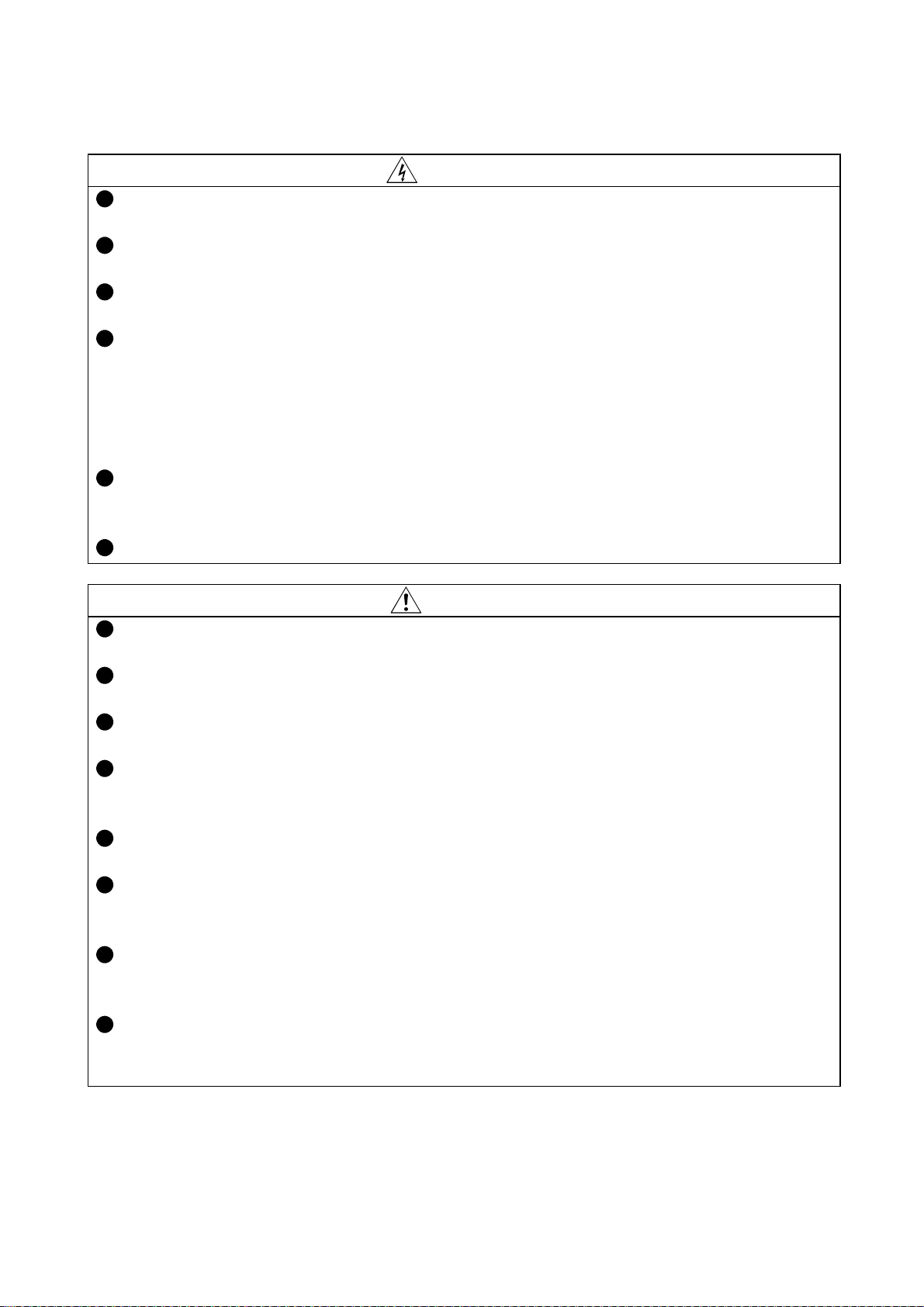
1.1.2 Type
Locations of the capacity plate and name plate and definitions of their
descriptions
Capacity
plate
Capacity plate
MD-CX522-0.4K/
Drive unit type
Name
plate
Input ra ting
Output rating
Serial number
Serial number
Name plate
MITSUBISHI
MODEL
MD-CX522-0.4K
INPUT :
XXXXX
OUTPUT :
XXXXX
SERIAL :
MITSUBISHI ELECTRIC CORPORATION
MADE IN JAPAN
MELIPM
Drive uni
type
PASSED
Type
C X 5 2 2M D - - K
Series
Capacity
Power supply: 3-phase 200V
1.1.3 Drive units to be used with motors
Use the drive unit with the specified dedic ated motor. In this case, confirm that
the capacity and rated speed of the drive unit always match those of the motor.
1
1-1
Page 12
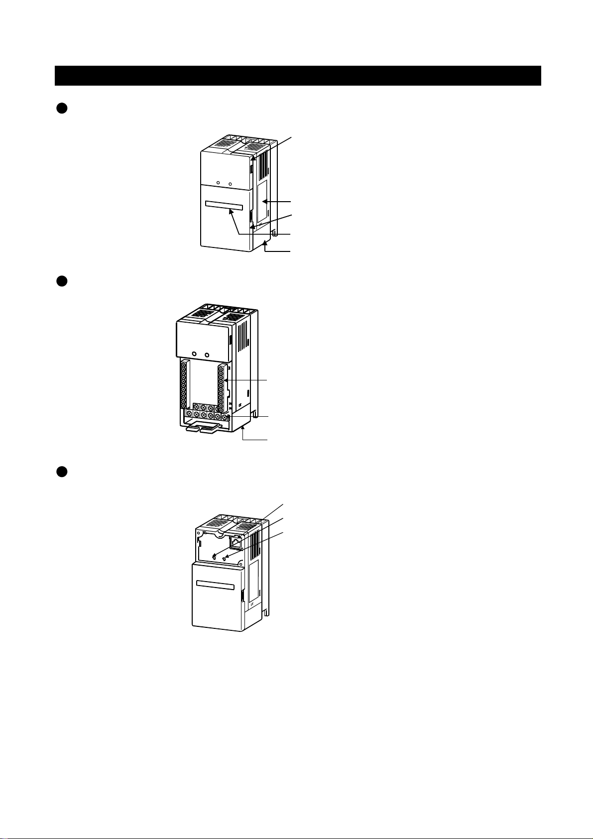
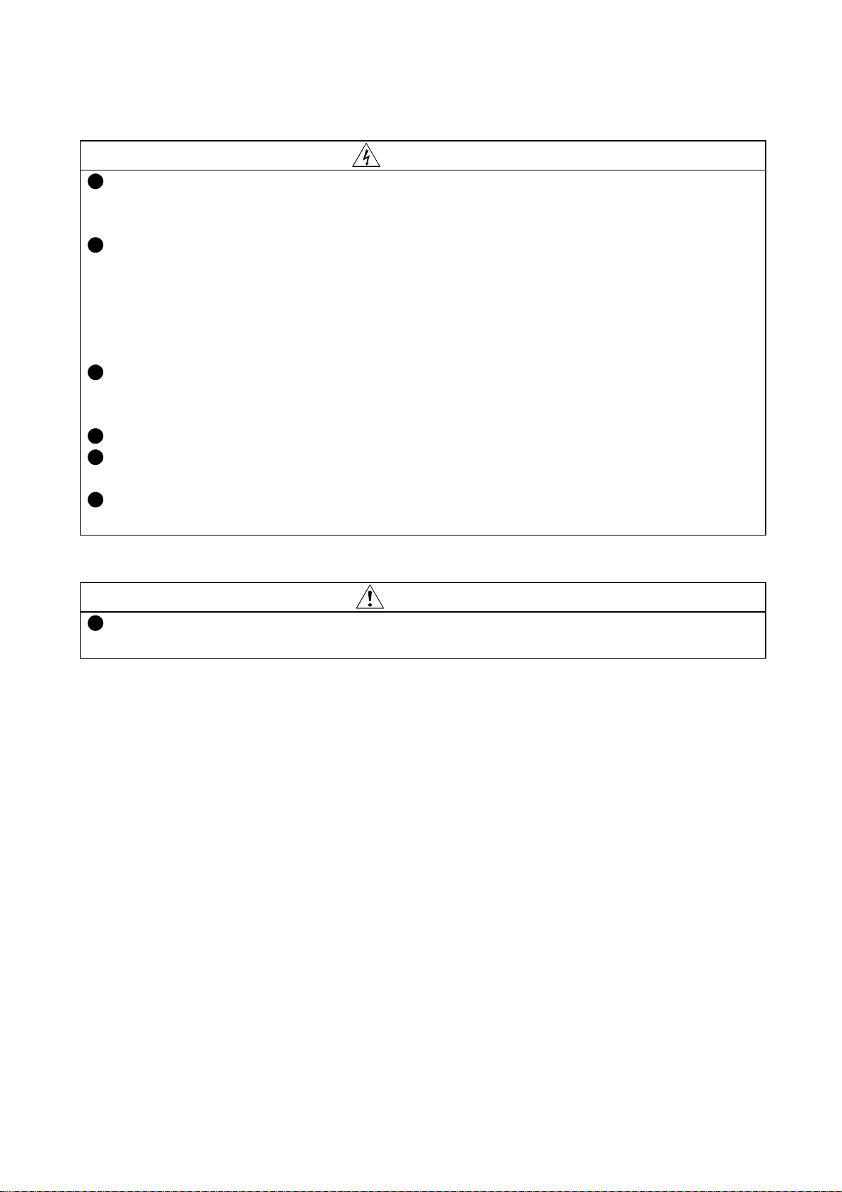
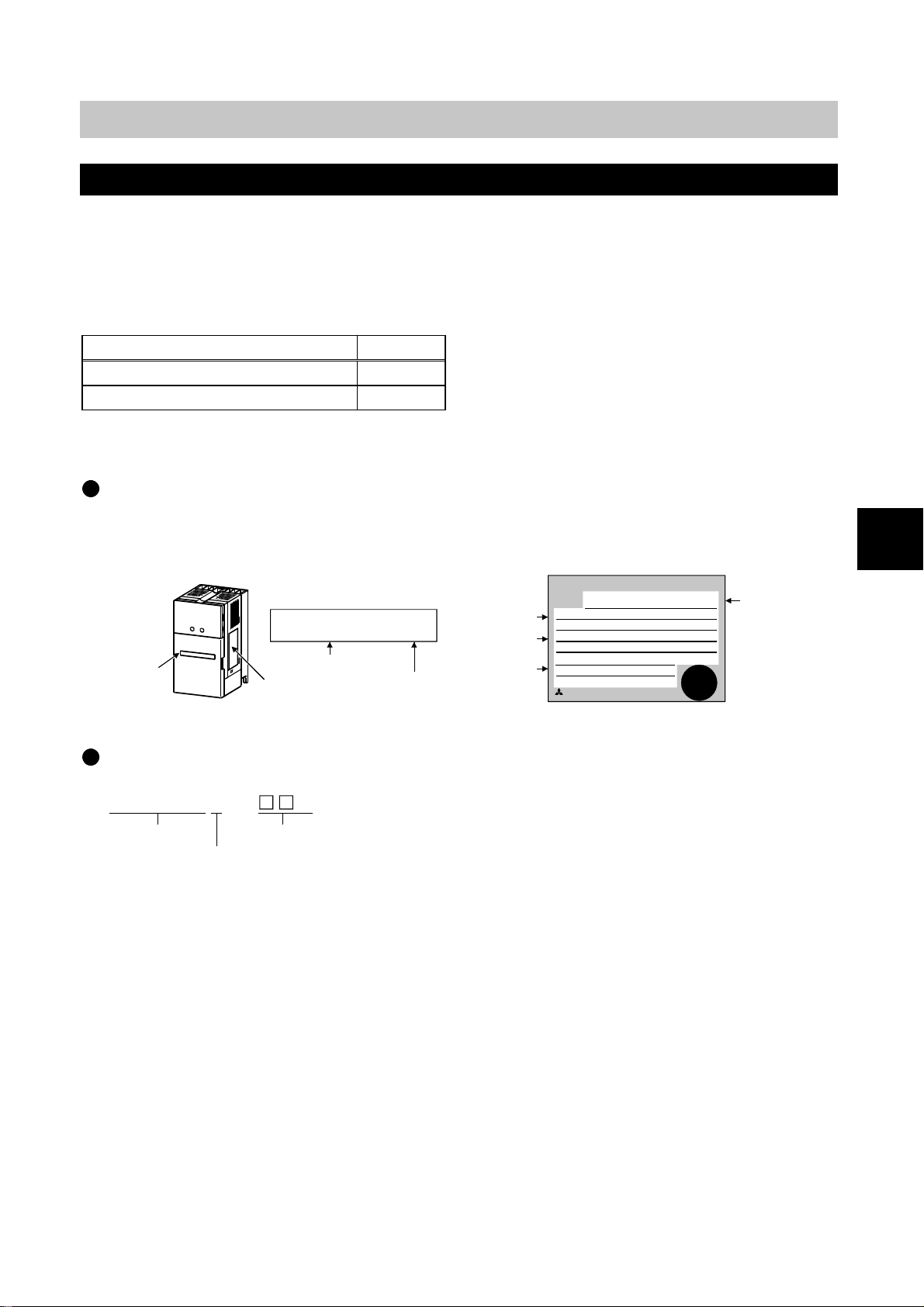
1.2 Parts Identification
Appearance of drive unit
Without front cover (Lower)
1. PRE-OPERATION INFORMATION
Front cover (Upper)
Name plate
Front cover (Lower)
Capacity pl ate
Wiring cover
Without front cover (Upper)
Control circuit terminal block
Main circuit terminal block
Wiring cover
PU connector
POWER lamp (Yellow)
ALARM lamp (Red)
1-2
Page 13
1. PRE-OPERATION INFORMATION
1.3 Handling of Covers and the Like
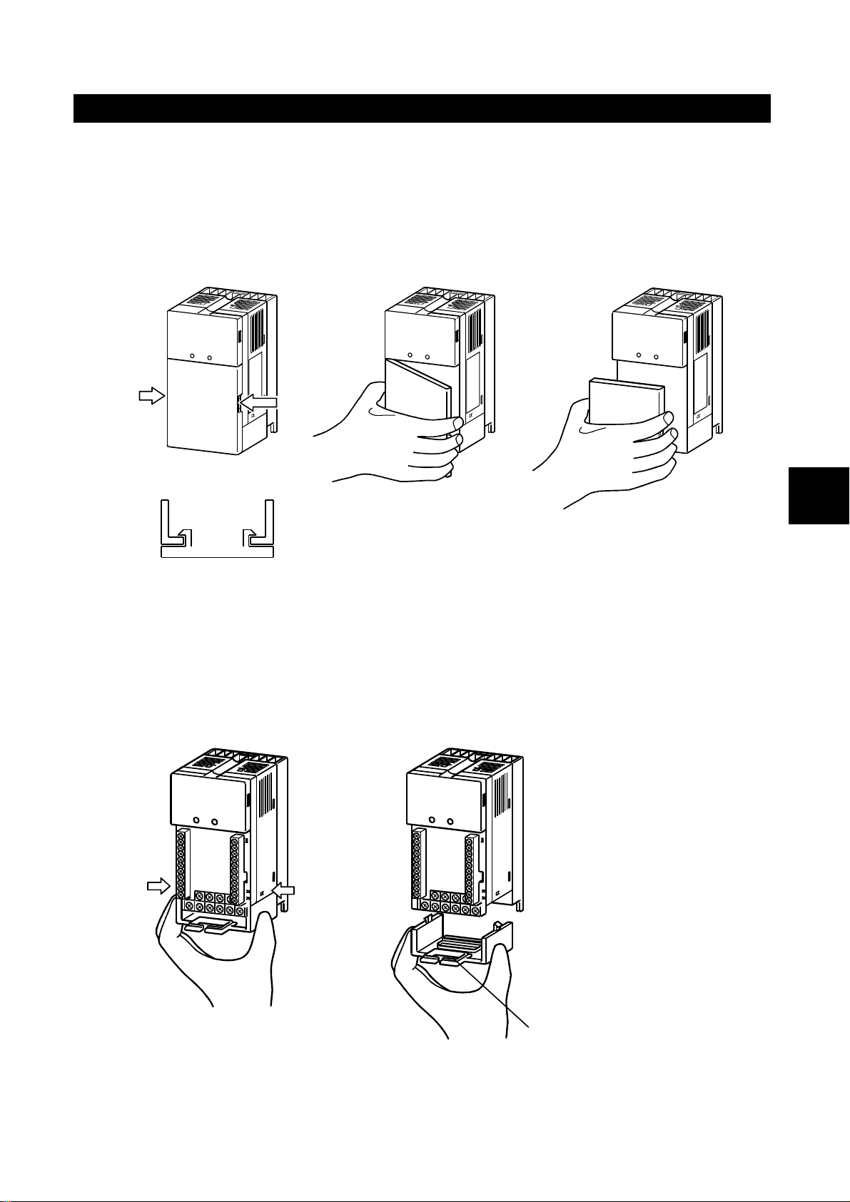
1.3.1 Removal and reinstallation of the front cover (Lower)
The front cover is fastened by the latches in positions A and B.
Push either A or B in the direction of arrow, and using the other end as a supp ort,
pull the front cover toward you to remove.
1) 2) 3)
A
B
To reinstall the front cover, fasten it with the latches securely.
1.3.2 Removal and reinstallation of the wiring cover
The wiring cover is fastened by the latches in positions 1 an d 2.
Push either 1 or 2 in the direction of arrow, and pull the wiring cover downward to
remove.
1
1)
2)
Wiring hole
Run the cables through the wiring hole and reinstall the cover securely in the
original position.
1-3
Page 14
1. PRE-OPERATION INFORMATION
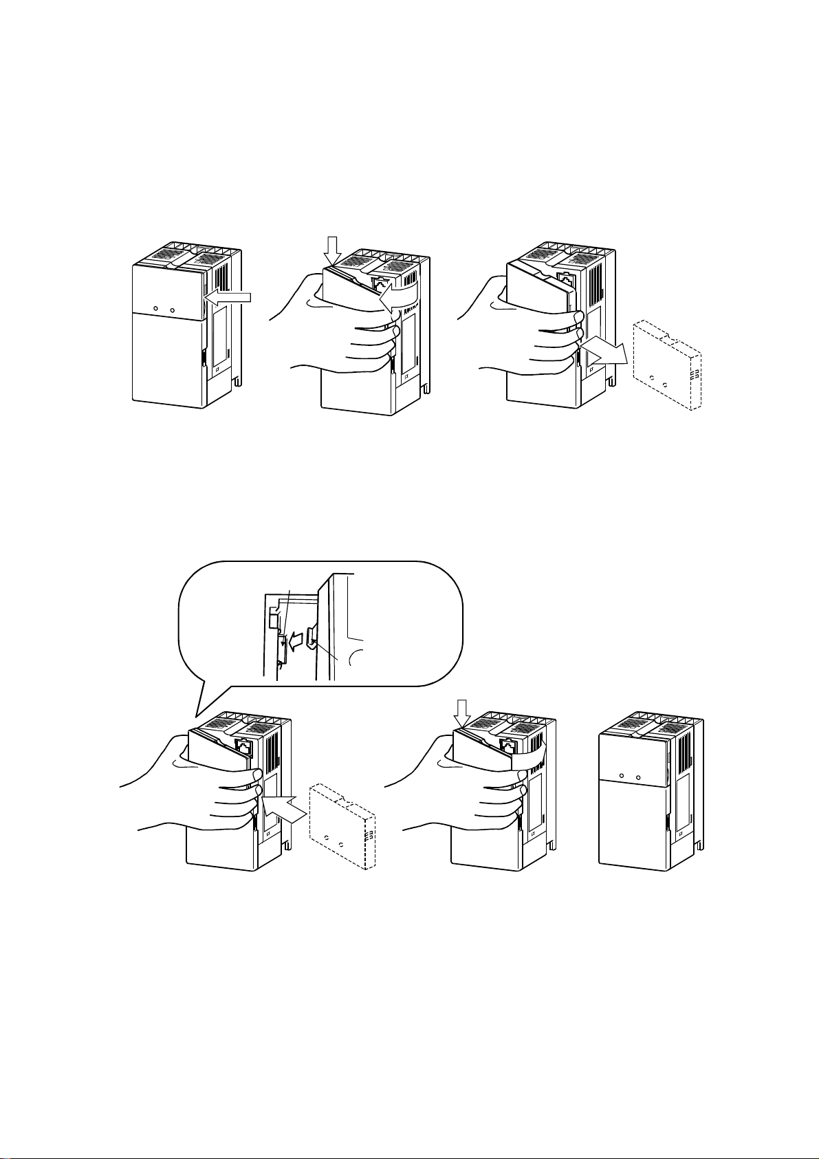
1.3.3 Removal and reinstallation of the operation panel
Hold down the arrow part A, and using the arrow part B as a support, pull the
right hand side of the operation panel toward you and remov e the panel
rightward.
A
2)
B
3)
1)
If the operation panel is remov ed in any other method, force will be applied to the
internal connector, damaging the panel.
To reinstall, insert the tab (left side) of the o peration panel into the mounting
position of the drive unit and push in the right hand side tab.
Mounting position
1)
Operation panel
Tab
2)
A
3)
1-4
Page 15

1. PRE-OPERATION INFORMATION
1.4 Transportation
When carrying, always support the whole drive unit.
1.5 Storage
Store the drive unit in the following environment.
Ambience
Ambient temperature
Storage temperature
Ambient humidity
Vibration
If the specification value of humidity is satisfied, c on densation
and/or freezing will occur in places where temperatures vary greatly.
NOTICE
Avoid storing the equipment in su c h places.
Avoid placing the unit directly on the floor. Place it on a stand or
shelf.
No corrosive gas, flammable gas, oil mist, dust and dirt.
No exposure to direct sunlight. No salt.
-10°C to +50°C (non-freezing)
-20°C to +65°C (applies to short-time transit)
90%RH or less (non-condensing)
5.9m/s2 (conformance with JIS C 0040)
1
1-5
Page 16

2. INSTALLATION
2. INSTALLATION
This chapter gives pre paratory information on installation and w iring of the drive
unit.
The Japanese harmonic suppression guidelines for suppression of
harmonics were established by the Ministry of Economy, Trade and
Industry (formerly Ministry of International Trade and Indu stry) in
September, 1994.
NOTICE
2.1 Checking the Installation Environment
2.1.1 Operating environment
To comply with the regulation levels determined by the Japan
Electrical Manufacturers' As sociation in accordance with the
"harmonic suppre s sion guideline for household appliances and
general-purpose products", connect the optional power factor
improving reactor (FR -BEL or FR-BAL).
General operating environment
Install the unit in the following environ ment.
Ambience
Ambient temperature
Ambient humidity
Altitude
Vibration
Indoors (No corrosive gas, flammable gas, oil mist, dust and dirt
No exposure to direct sunlight. No salt.)
-10°C to +50°C (non-freezing)
90%RH or less (non-condensing)
Maximum 1000m
5.9m/s2 (conformance with JIS C 0040)
CAUTION
Install the equipment on a non-flammable material. Not doing so can
cause a fire.
Do not place flammable materials near the equipment. Do ing so can
cause a fire.
Install the unit in a load-bearing place. No t doing so can cause an
accident.
Noise environment
Since drive is an electronic pie c e of equipment, the drive unit may malfunction if
there are machines whi ch g enerate large noises (e.g. welder, power equipment)
in the periphery. Fit surge suppressors, noise filters and/or like to the noise
sources, install the driv e unit as far away as possible from noise sources, or
place shielding plates and th e like to fully suppress noises.
2
CAUTION
The drive unit itself can be the source o f nois es. Take noise
suppression measures to pr event peripheral equipment from
malfunctioning due to noises.
2-1
Page 17
2. INSTALLATION
V
p
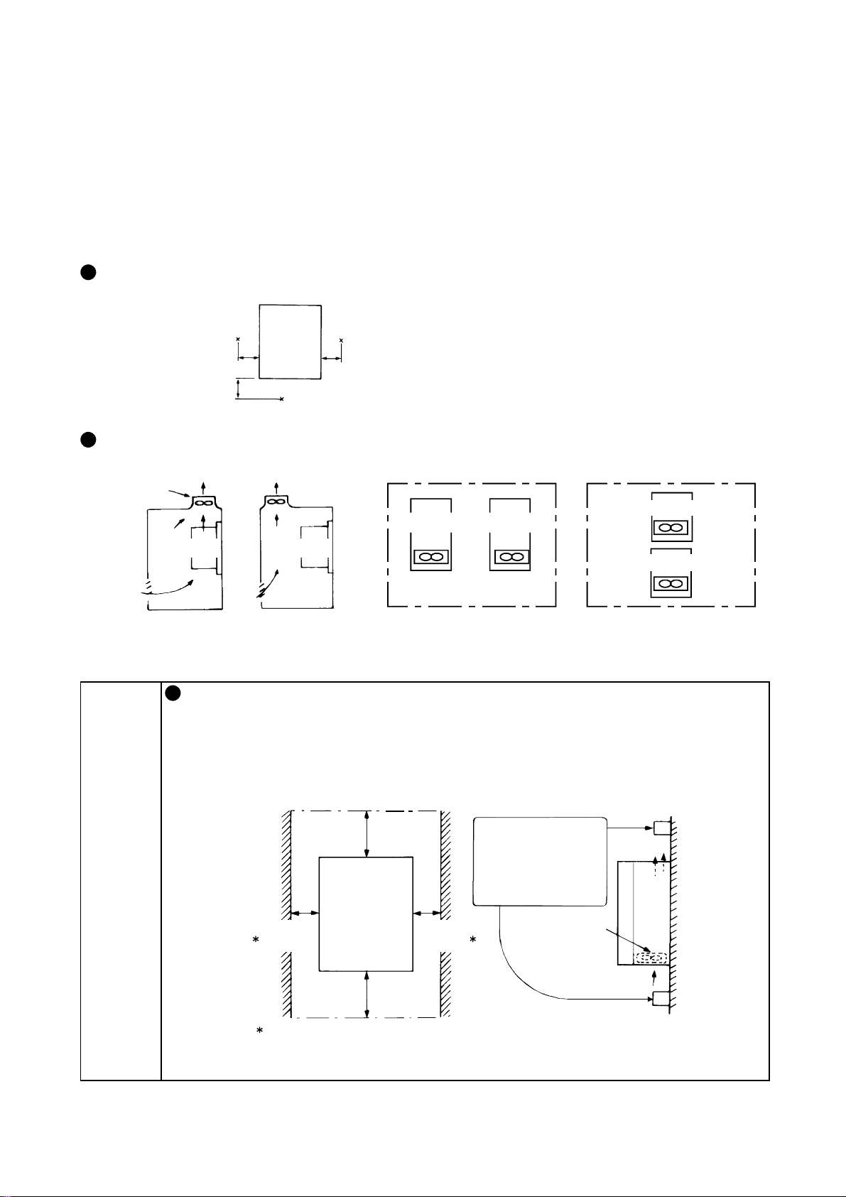
2.1.2 Installation in control box
When installing the drive unit in a cont rol box, the internal temperature of the
control box must not excee d the permissible value due to drive-unit generated
heat and peripheral-g enerated heat.
Placing a heat sink outside the control box can reduce the heat generated inside
the control box.
Measurement positions of ambient te mperatures
Drive
5cm 5cm
5cm
Layout of drive units within control box
entilation fan
Drive unit
(Correct example) (Incorrect example)
unit
Measurement position
Drive unit
Measurement position
Drive unit Drive unit
Position of ventilation fan
Leave the specified clearances between the drive unit and control
box walls or other equipment. Not doing so can cause a failure. In
addition, improper convection of air in the control box w ill reduce the
heat dissipation effect. Fully consider the equipment layout in the
control box and the use of a cooling fan for ventilation, for example.
Drive unit
Drive unit
Built-in cooling fans
(Incorrect example)(Correct example)
Accommodation of two or more drive units
NOTICE
10cm
or more
1cm
or more
These clearances are also required for
lacement of the cooling fan.
re
Drive unit
10cm
or more
1cm
or more
Leave sufficient
clearances above
and under the drive
unit to ensure
adequate ventilation.
Cooling fan built
in the drive unit
Cooling
air
2-2
Page 18
2.2 Preparation of Peripheral Devices
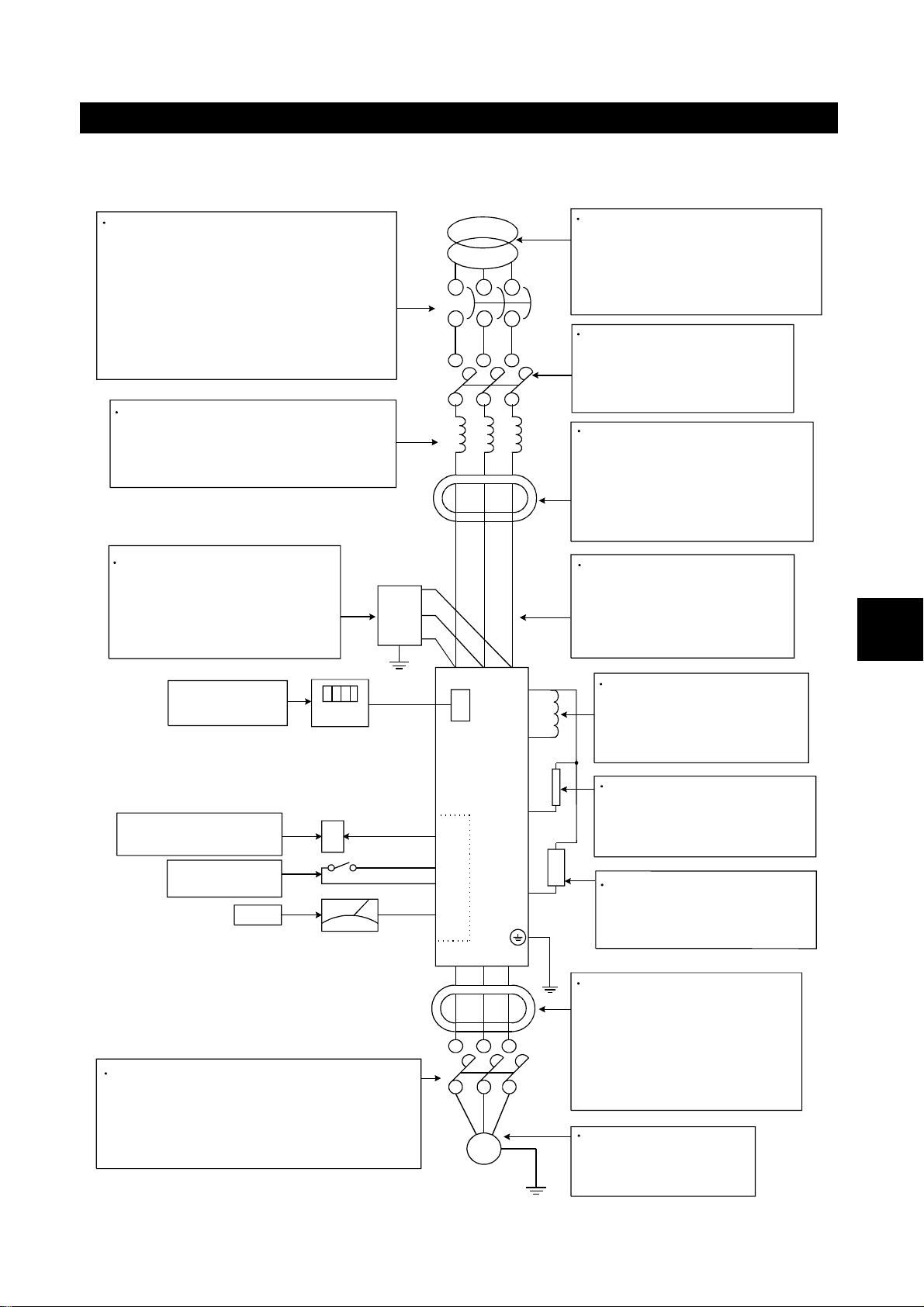
2.2.1 Basic configuration
2. INSTALLATION
No-fuse breaker or earth leakage
circuit breaker
Always connect either of the above for
circuit (wiring) protection. Make selection
in accordance with the selection table.
Choose the earth leakage circuit breaker
which has harmonic suppression.
Refer to: 2.2.2 Selection of peripheral
devices
Reactor (FR-BAL)
Install it for power factor improvement,
power coordination, or harmonic
suppression.
Radio noise filter (FR-BIF)
Connect it to reduce radio noise
in the AM frequency band.
This filter is designed for use on
the input side only.
Power equipment capacity
As the power equipment capacity,
select the kVA value not less than
the one given in the specifications.
Refer to: Chapter 7, 7.1.1
Rating specifications
Magnetic contactor
Make selection in accordance
with the selection table.
Refer to: 2.2.2 Selection of
peripheral devices
Line noise filter
(FR-BSF01) (FR-BLF)
Connect it to reduce high
frequency noises outgoing to the
power supply side.
Its effect is higher as the number
of wire turns is greater.
Main circuit cables
Choose the wire size in
accordance with the selection
table.
Refer to: 2.2.2 Selection of
peripheral devices
2
Parameter unit
(FR-PU04)
Analog signal
setting potentiometer
Contact signal
switch
Meter
Low-voltage manual switch
Connect it in any application where the
motor is run by the load after the drive unit
has been powered off.
Refer to: Page 3, 1. Usage
RST
PU
connector
I/O
UVW
V
U
Motor
M
P/+
P1
PR
N/-
W
Reactor (FR-BEL)
Install it for power factor
improvement, power
coordination, or harmonic
suppression.
Brake resistor (MRS)
(FR-ABR)
Connect it to increase braking
capabili ty for de cele ration.
BU brake unit, Discharge
resistor
Connect it to increase braking
capabili ty for de cele ration.
Line noise filter
(FR-BSF01) (FR-BLF)
Connect it to reduce high
frequency noises outgoing to
the output side.
When installing it on the output
side, do not turn the wire more
than four times.
Magnetic motor
Use the specified motor.
It cannot be run using
commercial power.
2-3
Page 19
2. INSTALLATION
2.2.2 Selection of peripheral devices
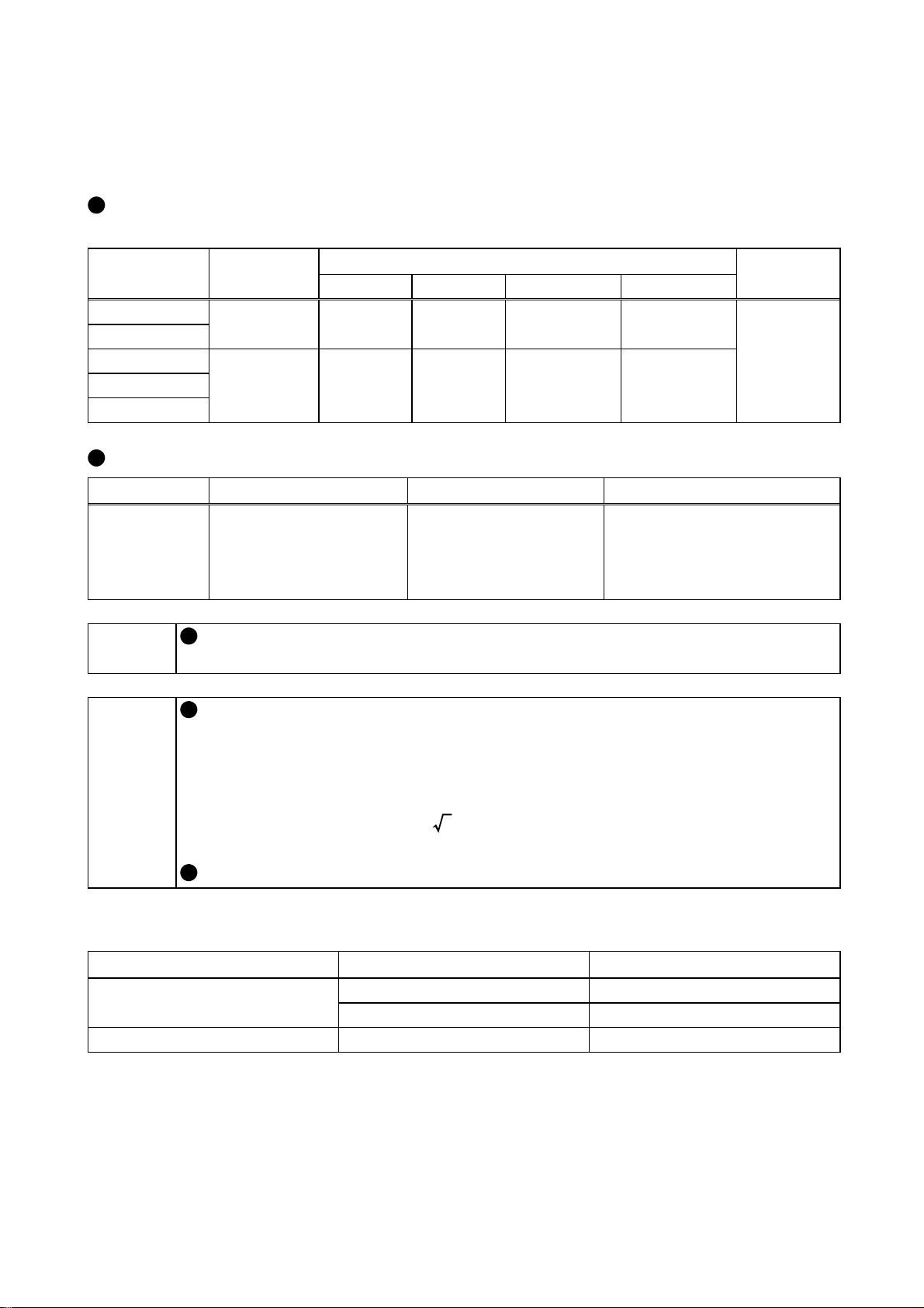
(1) Wire size
AC power input terminals R, S, T, motor connection terminals U, V, W, DC
reactor connection terminals P/+, P1, DC te rminals P/+, N/-, ground terminals
Capacity (K)
0.4
0.75
1.5
2.2
3.7
Control circuit terminals (all terminals)
Capacity Terminal Screw Size
All capacities M2.5 0.3 to 0.75
Terminal
Screw Size
M3.5 2 2 2 2
M4 2 to 5.5 2 to 5.5 2 to 5.5 2 to 5.5
R, S, T U, V, W P/+, P1, N/- Connection
Wire Sizes, Unit: mm
Wire Size, Unit: mm
2
Wire Type
Power
cable 600V
vinyl wi r e
equivalent
2
Twisted shielded wire,
polyethylene insulated vinyl
wire for instrumentation or
equivalent
Wire Type
or
Refer to the corresponding instruction manual for wires connection
MEMO
of a stand-alone option conne cted to the DC terminals P/+, N/-.
Choose the size of the wires connected to the motor connection
terminals so that a voltage drop due to the w ires is less than 4V.
The minimum wire siz e in the above selection table a s sumes that
the wiring length is less than 20m.
NOTICE
A voltage drop can be found by the following expression:
Line voltage drop (mV) =
Use the ground cable which is as thick as possible.
(2) Crimping terminals
Wire Size, Unit: mm
2
3.5/5.5 M4 5.5-4
2
3 × wire resistance (Ω/km)
× wiring length (m) × current (A)
Terminal Screw Size Crimping Terminal Size
M3.5 2-3.5
M4 2-4
2-4
Page 20
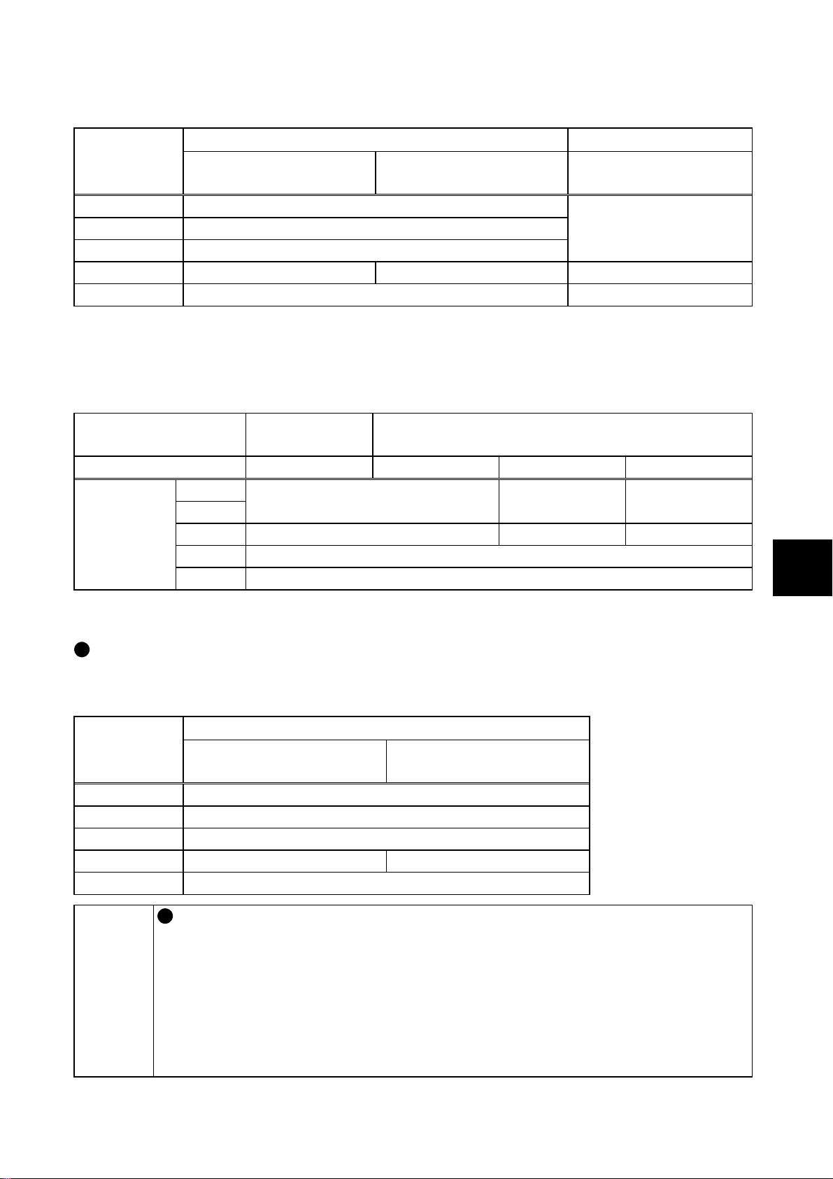
(3) No-fuse breakers, magnetic contactors
2. INSTALLATION
No-Fuse Breaker
Capacity (K)
0.4 30AF/5A
0.75 30AF/10A
1.5 30AF/15A
2.2 30AF/15A 30AF/20A S-N11, S-N12
3.7 30AF/30A S-N20
With power factor
improving reactor
Without power factor
improving reactor
Magnetic Contactor
With power factor
improving reactor
S-N10
If the magnetic contactor does not have power factor improving react or, s elect
the magnetic contactor as indicat ed in the following table depending on the
power equipment capacity and the w i ring length from the power equipment to the
drive unit.
Power Supply
Capacity
Wiring length
Capacity
(K)
0.4
0.75
1.5 S-N21 S-N25 S-N50
2.2 S-N11, S-N12
3.7 S-N20
Less than
50kVA
50kVA or More
20m or more 10m to 20m Less than 10m
S-N18 S-N21 S-N21
2
(4) Earth leakage circui t breakers
Selection method
Use the earth leakage circuit breaker which ha s harmonic/surge su ppression.
Our product: Progressiv e Super Series NV-SF, NV-CF
Earth Leakage Circuit Breaker
Capacity (K)
0.4 30AF/5A
0.75 30AF/10A
1.5 30AF/15A
2.2 30AF/15A 30AF/20A
3.7 30AF/30A
With power factor
improving reactor
Leakage currents from the wiring and motor include frequency
Without power factor
improving reactor
components of a higher degrees than those from the commercial
power supply. Therefore, the earth leakage cir cuit br eaker which is
not a harmonic/surge suppression produc t can cause unnecessa ry
MEMO
operations.
<Measures again st u nnecessary operations >
•
Minimize the wiring distance of I/O cables.
•
Run I/O cables away (mor e than 30cm) from the earth.
2-5
Page 21

2. INSTALLATION
2.3 Installation Method
1) Remove the front covers. (Up per and lower)
2) Remove the wiring cover.
3) Pass screws or bolts into the four mountin g holes and secure the drive unit.
(Three mounting holes for 0.75K or les s)
CAUTION
Prevent screws, metal pieces and other conductive foreign matter and
oil and other flammable foreign matter from entering the drive unit.
Securely screw or bolt the unit to the m ounting surface vertically
without looseness. Always install the unit in the specified mounting
orientation. Not doing so can cause a failure.
Do not drop the unit, or subject it to impact.
4) Replace the removed cover. Leave the cover re moved when continuing the
wiring work.
Fully check that the front cover has been mounted securely.
Insecure mounting can cause a drop due to vibration.
The front cover (Lower) is fitted wi th the c apacity plate and the drive
NOTICE
unit with the name plate. The same serial number is printed on
these plates. Always reinstall the c over to the drive unit from where
it had been removed.
2-6
Page 22

3. WIRING
3. WIRING
This chapter describes the wiring of the drive unit.
WARNING
Any person who is involved in the wiring of this equipment should be
fully competent to do the work. Otherwise, an electric shock or fire can
occur.
Always install the unit before wirin g. Otherwise, an electric shock or
fire can occur.
Before restarting wiring after switching power "ON", make sure that the
motor is at a stop, wait for more than 10 minutes after switching power
"OFF", and confirm that the DC voltage across the DC terminals P/+
and N/- is low enough to do wiring. Immediately after power "OFF", the
DC terminals P/+, N/- are charged with more than 200V (residual
voltage of the internal capacitor). Therefore, an electric shock may
occur.
Even after power-off, the motor connection terminals U, V, W hav e high
voltages while the motor is running. Always start wiring after
confirming that the mo tor has stopped. Not doing so can cause an
electric shock.
CAUTION
Take measures to prevent peripheral sensors and equipm ent from
malfunctioning due to electromagne tic noises. Not doing so can cause
accidents.
Take measures to prevent peripheral power capacitors and generators
from overheating or being damaged du e to power harmonics. Not
doing so can cause a fire.
Do not leave wire offcuts in the drive unit. Doing so can cause a fault,
failure or malfunction.
If the machine must not be restarted when power is restored after a
power failure, provide a magnetic contactor on the power supply side
and also make up a sequence which will not turn "ON" the start signal
automatically when power is restored.
Tighten the terminal screws to the specified torque. Undertightening
can cause an inter-terminal short circuit or malfunction. Overtightening
can cause the screws and unit to be damaged, resulting in a short
circuit, malfunction or the like.
3
3-1
Page 23

3. WIRING
3.1 Pre-Wiring Instructions
3.1.1 Terminal connection diagram
The following shows the wiring of all terminals. After confirming the function of
each terminal, wire necess ary terminals according to your application. When the
Parameter unit is used to perfor m operation, merely doing the main ci rc uit wiring
enables the motor to run.
Main circuit terminal
Control circuit terminal
Motor
Ground
Jumper
Power factor improving reactor
FR-BEL (option)
Brake resistor
R
Running
Up to speed
Transistor
output common
+
Calibration
resistor
Pulse output
(0 to 1440
pulses/s)
FR-ABR (option)
Contact output
terminals
Transistor
output
terminals
Meter
connection
terminals
3-phase AC
power supply
Contact input
terminals
Speed
command
input
terminals
NFB
External transistor common
Forward
rotation start
Reverse
rotation start
High speed
Middle speed
Low speed
Output stop
Reset
Voltage
Speed setting
potentiometer
Common
input
Drive unit
PU connector
R
(RS-485)
S
T
U
V
W
P1
PC
P/+
STF
STR
PR
RH
RM
N/-
RL
A
B
MRS
RES
C
RUN
FU
Contact
input
SD
common
10(+5V)
DC0 to 10V
2
DC0 to 5V
5(Analog common)
4
(Keep this terminal open)
Switched
SE
FM
SD
*This resistor is not needed when you use the
parameter unit (FR-PU04) to make calibration. This
resistor is used when you need to calibrate the meter
nearby because the meter is at a remote location, for
example. Note that when you connect the calibration
resistor, the meter may not deflect to the full scale. In
this case, use the parameter unit with the resistor to
make calibration .
3-2
Page 24
3.2 Wiring of the Main Circuit Terminals
3.2.1 Terminals
Symbols Name Description
R, S, T
U, V, W
P/+, PR
P/+, P1
P/+, N/- DC terminals Connect to the BU brake unit (option).
3.2.2 Terminal layout and connection specifications
AC power input
terminals
Motor connection
terminals
Brake resistor
connection terminals
DC reactor
connection terminals
Ground terminals
Connect to the commercial power supply.
Connect to a dedicated variable-speed synchronous
motor.
Connect the brake resistor (option).
Disconnect the jumper from terminals P/+-P1 and
connect the FR-BEL power factor improving DC
reactor (option).
Terminals for connection of the ground cables. (There
are two terminals.)
3. WIRING
CX522-0.4, 0.75K CX522-1.5K to 3.7K
Layout
Screw size
M3.5
N/-
P1
R/L1S/L2T/L3
P/+
PR
UVW
TB1
Tightening torque
1.2N•m
Layout
N/-
PR
TB2
Screw size
M4
P/+
P1
R/L1S/L2T/L3
UVW
TB1
Tightening torque
1.5N•m
CAUTION
Tighten the terminal screws to the specified torque. Undertightening
can cause an inter-terminal short circuit or malfunction. Overtightening
can cause the screws and unit to be damaged, resulting in a short
circuit malfunction or the like.
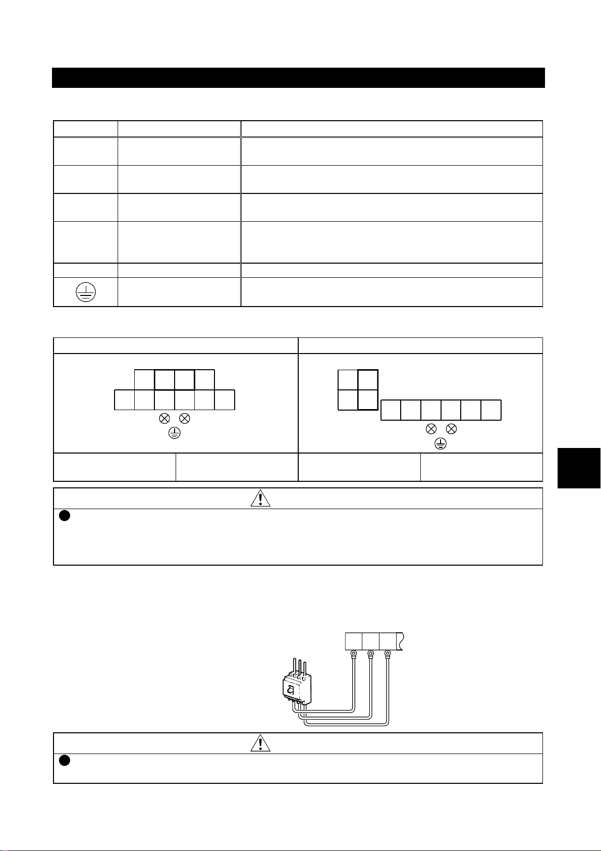
3.2.3 Wiring of the AC power input terminals R, S, T
Connect these terminals to the AC power supply. You need not match the phase
sequence.
3
Power supply
No-fuse breaker
RST
RST
CAUTION
Always apply power to only the AC power input terminals R, S, T.
Applying power to the other terminals will damage the unit.
3-3
Page 25
3. WIRING
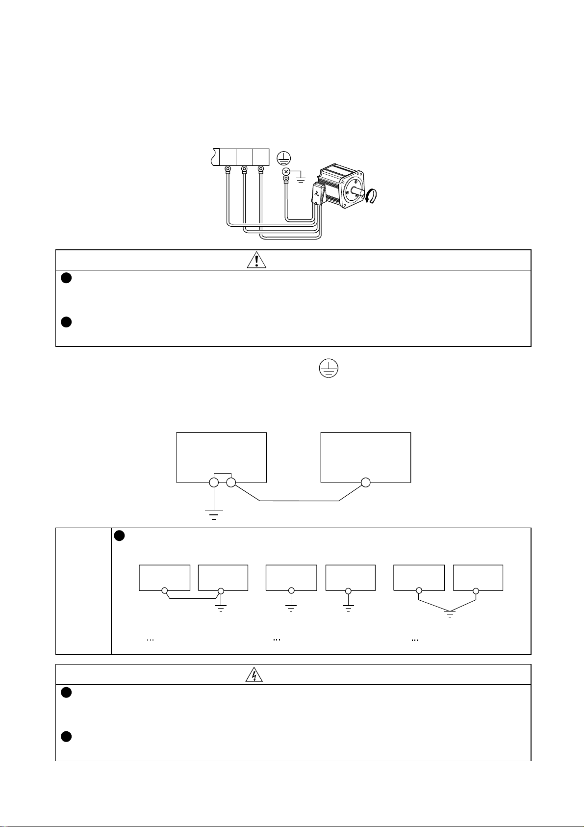
3.2.4 Wiring of the motor connection terminals U, V, W
Connect these terminals to the mot or. Match the phase sequence of the motor
connection terminals U, V, W with that of the motor cables. Incorrect phase
sequence will run the motor in reverse.
UVW
UVW
Ground
terminal
Ground
Motor
CAUTION
The wiring length between the drive unit and motor should be 100m
maximum. Long wiring may cause torque to be insufficient or the
overcurrent protecti on function to be activated.
Between the drive unit and motor, do not fit a power capacitor, surge
suppressor or FR-BIF radio n oise filter (option).
3.2.5 Wiring of the ground terminals
There are two ground terminals. Connect one ground terminal to the motor's
ground terminal and perform shared grounding on the drive unit.
Drive unit
Motor
Avoid shared grounding with the other equipment susceptible to
noise, and perform exclusive or single-point grounding.
Drive unit Drive unit
Other
equipment
Other
equipment
Drive unit
Other
equipment
NOTICE
Shared grounding
Not allowed
Exclusive grounding
Allowed
1-point grounding
Allowed
WARNING
Ground the drive unit and moto r securely to prevent an elect ric shock
due to leakage currents. (Class D grounding, grounding resistance
ΩΩΩΩ
100
For grounding, connect the cable to the exclusive ground terminal. (Do
not use the screw of the casing, chassis or the like.)
max.)
3-4
Page 26

3. WIRING
3.2.6 Wiring of the DC reactor connection terminals P/+, P1
These terminals are designed for connection of the pow er factor improving
reactor (FR-BEL).
Remove the jumper acros s the ter minals P/+-P1 and connect the DC reactor.
<Connection method>
CX522-0.4K,0.75K CX522-1.5K to 3.7K
N/-
P1
Remove jumper.
P/+
PR
FR-BEL
P/+
Remove jumper.
P1
FR-BEL
NOTICE
MEMO
The wiring distance (overall length) should be within 5m.
Without removal of the jumper, the reactor will not be active.
3.2.7 Wiring of the brake resistor connection terminals P/+, PR
These terminals are de signed for connection to the b rake resistor (heavy-duty
brake resistor).
Change Pr. 30 and Pr. 70 setting s before use.
NOTICE
Connect only the specified brake resistor.
3.2.8 Wiring of the DC terminals P/+, N/-
These terminals are designed for connection of the B U br ake unit.
1) Connect the BU brake unit. For full infor mation, re ad the BU brake unit
instruction manual.
2) Change the Pr. 30 setting.
NFB
R
S
T
U
V
W
Motor
M
3
P/+ N/-
N
P
BU brake unit
CAUTION
Do not connect the brake r esistor or the like to the DC terminals P/+,
N/- directly. Doing so can cause a fire.
Incorrect (opposite) connection to the DC terminals P/+, N/- will
damage the drive unit.
3-5
Page 27

3. WIRING
3.3 Wiring of the Control Circuit Terminals
CAUTION
Use shielded or twisted cables for wiring the control circuit input
terminals. Also run them a way from the main circuit wiring and other
power cables. Not doing so can caus e a malfunction due to noise.
3.3.1 Terminals
(1) Contact input termin al s
Turning the signal acro s s any terminal and common terminal "ON" (closing
those terminals)/"OFF" (opening those terminals) provides the corresponding
function as described below.
The shaded terminal sy mbol s indicate that their functions can be changed.
Refer to: Chapter 8, 8.4 Selection of the Control
Circuit Contact Input Terminal Functions
Symbol Name Description
STF
STR
RES Reset
MRS Output stop
RH
RM Middle speed
RL Low speed
SD
PC
Forward
rotation start
Reverse
rotation start
High speed
Contact input
common
External
transistor
common
Turn on this signal to start forward
rotation or turn it off to stop.
Turn on this signal to start reverse
rotation or turn it off to stop.
Turn on this signal (for more than 0.1s) to reset the protective
circuit activated. Turn it off after the protective circuit is reset.
Turn on this signal (for more than 0.1s) to stop the output and
separate the motor electrically, causing it to coast. Turing it off
with the start signal input will restart the motor at the starting
speed.
Combine on/off of these signals as appropriate to select
multiple speeds.
Refer to: Chapter 8, 8.3.2 Variable-speed
operation using contact input signals
Common to the contact input terminals. (Not isolated from
terminal 5.)
Common terminal used when the contact input terminal is
connected to the transistor output (open collector output) of the
external controller. This terminal can prevent a malfunction
caused by a sneak current.
Simultaneously
turning on these
signals gives a stop
command.
MEMO
Ratings of the contact input terminals
Input resistance: 4.7kΩ, open-time v oltage: 24±3VDC,
short circuit-time current: 4 to 6mADC
Use the terminal PC as a power su pply terminal.
Can be used as a power supply for a sensor or equivalent. The
common terminal is the terminal SD (digital common).
Power supply voltage ra nge: 24±2VDC, max. permissible
current: 100mA
When the terminal is used as a pow er supply, it cannot be used as
an external transistor common terminal to prevent a sneak current.
The response time of the contact input terminal is 2 0ms±15ms.
(When the stall preventi on function is activated, response may be
slower.)
Terminals SD and 5 are not isolated.
3-6
Page 28

When a transistor is used to input the signal of the contact input
terminal, make sure that the electrical characteristics of the
transistor used sati sfy the following:
: Collector current, 10mA o r more
I
C
: Open-time collector-emitter permissible voltage, 30V or
V
CEX
more
NOTICE
V
: Conduction-time collector-emitter saturation voltage, 3V
CE(sat)
or less
: Collector shutoff curre nt (leakage current), 100uA or le ss
I
CEX
When a relay contact is used to input the signal of the contact input
terminal, use two faint signal contacts in parallel or use a twin
contact to prevent a contact fault.
(2) Speed command input terminals
Terminals used to v ary the motor speed with analog signals.
The parameter function allows you to choose the analog speed command
specifications.
Refer to: Chapter 8, 8.3.1 Selection of the analog
speed command specifications
3. WIRING
Symbol Name Rating Description
2
4 Keep this terminal open.
5
10
Voltage
input
Analog
common
Power
supply 5V
Input resistance: 10±1k
Max. permissible voltage:
20VDC
5V±0.2VDC
Permissible load current:
10mA
You can perform operation at the
Ω
speed proportional to a 0 to 10VDC (or
0 to 5VDC) voltage signal.
Common to the speed command input
terminals. Do not earth.
Can be used as a power supply for the
analog input signal, e.g. speed setting
potentiometer.
The common terminal is terminal 5.
(3) Transistor output terminals
When the function of any terminal is activated, the internal transistor (open
collector output) connected across that ter mi nal and common terminal turns
ON (conducts).
You can set the parameter function to ch ange the function of each terminal.
Refer to: Chapter 8, 8.7.2 Selection of the control
circuit output terminal functions
Chapter 8, 8.7.3 Detection of running speed
Symbol Name
RUN Running
FU
SE
Speed
detection
Transistor
output
common
ON (conducts) while the drive unit is outputting a speed command
to the motor. OFF (does not conduct) during stop or coasting.
Turns ON (conducts) when the speed output by the drive unit
reaches or exceeds the preset value. OFF (does not conduct)
when the speed is less than that.
Common to the transistor output terminals. Isolated from the
terminals SD, 5.
Description
3
3-7
Page 29

3. WIRING
Ratings of transistor output terminals
MEMO
Max. permissible voltage: 27VDC, max. permissible current:
0.1ADC
When driving a coil load, connect a diode.
NOTICE
Refer to: 3.3.5 Wiring of the transistor output
terminals
(4) Contact out put terminals
When the protective function is activated, the relay contact connected to the
terminal opens/close s.
Refer to: Chapter 6, 6.1.1 Protective function
activated
Symbol Contact Capacity Description
Normal : Terminals B-C closed
A, B, C
200VAC 0.3A or
30VDC 0.3A
Protective function activated: Ter m in a ls B- C op e n
(Terminals A-C open)
(Terminals A-C closed)
The response time of the contact output terminals i s less than
100ms. (After drive unit output shutoff)
When the drive unit is powered off, the contact output is placed in a
MEMO
normal status. Therefore, the contact output signal is not held when
power is switched off after the protective function has been
activated. When the signal must be held, provide an external
holding circuit.
(5) Instrument connectio n terminals
Used to display the motor speed externally.
You can use the parameter function to choose the item other than the motor
speed.
Refer to: Chapter 8, 8.7.5 Selection of the instrument
connection terminal functions
Symbol Name Description
The output voltage has an 8VDC pulse waveform.
The output varies in proportion to the motor speed and the average
voltage is preset to approx. 4.7V at the rated speed and 1440
pulses/s.
As a meter, use a 1mA moving-coil type DC ammeter or digital
counter.
As the common terminal, use terminal SD.
FM
Meter
connection
MEMO
The output signal from the FM ter minal is updated at intervals of
several 10ms.
3-8
Page 30

3.3.2 Terminal layout and connection specifications
Layout
Terminal layout of control circuit
3. WIRING
A
B
C
10
2
5
4
SD
STF
STR
SD
0.25N•m to 0.49 N•m
Screw size
RH
RM
RL
MRS
RES
SD
FM
PC
SE
RUN
FU
Tightening torque
M2.5
Wiring method
1) For wiring the control circuit, use cables after stripping their sheaths.
Refer to the gauge printed on the drive unit and strip the sheaths to the following
dimensions. If the sheath is stripped too much, its cable may be shorted with the
adjoining cable. If the sheath is stripped too little, the cable may come off.
7mm 1mm
+
2) When using bar terminals and solid wires for wiring, their diameters should be 0.9mm
maximum. If they are larger, the threads may be damaged during tightening.
3) Loosen the terminal screw and insert the cable into the terminal.
4) Tighten the screw to the specified torque.
Undertightening can cause cable disconnection or misoperation. Overtightening can
cause damage to the screw or unit, leading to short circuit or misoperation.
Tightening torque: 0.25N
•
m to 0.49N•m
* Use a screwdriver No. 0 to tighten.
Note: When routing the stripped cables, twist them so that they do not become loose.
In addition, do not solder it. Soldering can cause poor contact.
When using a bar terminal or a solid wire for wiring, use one of
0.9mm or less diameter. Using one of larger diameter may damage
NOTICE
the threads during tight ening.
Connect stripped cable s o that its core does not become loose . Not
doing so can cause shorting of adjacent cables.
3
3-9
Page 31

3. WIRING
3.3.3 Wiring of the contact input terminals
Use shielded or twisted shielded cables for wiring. Con nect one shield sheath to
the common terminal. Leave the other shield sheath open.
When using contact signals
The following shows the wiring of the terminals STF, STR. The sa me wiring also
applies to the other terminals.
The terminal SD is a common terminal.
Drive unit
R
STF
R
STR
DC24V
SD
When using non-contact switches
When using transistor outputs having an external power supply, such as a PLC,
to input signals, perform the followin g w iring to prevent a malfunction caused by
a sneak current from the external power supply.
The following shows the wiring of the terminals STF, STR. The sa me wiring also
applies to the other terminals.
The terminal PC is a common terminal.
PLC
1
2
9
10
Drive unit
STF
STR
PC
SD
DC24V
External power sup pl y
Do not apply voltages to the contact input termi nals.
Do not short the terminals PC and SD. Doing so will damag e the
NOTICE
unit.
When the terminal PC is used as a power supply terminal, the
wiring length should be within 30m.
3-10
Page 32

3. WIRING
3.3.4 Wiring of the speed command input terminals
Use shielded or twisted shielded cables for wiring. Con nect one shield sheath to
the terminal 5. Leave the other shiel d sheath open.
The following diagram sh ows the wiring of the terminal 2.
The same wiring also a pplies to the other terminals.
Drive unit
10
2
5
3.3.5 Wiring of the transistor output terminals
The terminal SE is a common terminal.
Drive unit
RUN
FU
SE
DC24V
1
R
R
2
R
R
9
When driving a coil load such as a relay coil, always connect the followi ng diode.
Connect the diode with co rr ect polarity. Opposite polarity will cause the drive unit
to fail.
Drive unit
3
NOTICE
RUN
Relay
SE
DC24V
Terminal SE is isolated from terminals SD and 5. Do not connect
them each other.
3-11
Page 33

3. WIRING
3.3.6 Wiring of the contact output terminals
The following wiring example assumes that when the protective circuit is
activated, the magnetic contactor (MC) on the power supply side is opened to
switch off the ma i n circuit power.
Drive unit
R
S
T
B
C
Power supply
Stop
NFB
F
Operation-ready
MC
MC
MC
3.3.7 Wiring of the instrument connection terminals
MEMO
Drive unit
FM
SD
Meter
Calibration resistor
The calibration resistor is not needed when the parameter unit is
used to make calibrat ion.
Refer to: Pr. 900 [Section 8.7. 5]
3-12
Page 34

3.4 Wiring of the PU Connector
3.4.1 Pin layout
As seen from the drive unit (receptacle side) front
3. WIRING
1) SG
2) P5S
3) RDA
4) SDB
8) to 1)
5) SDA
6) RDB
7) SG
8)P5S
Pins No. 2 and 8 (P5S) provide power to the operation panel. Do
NOTICE
not use them when making RS-48 5 c ommunication.
3.4.2 Using the cable to connect the parameter unit
Use the optional "FR-CB2 parameter unit connection cable" or c ommercially
available connector and cable for wiring.
Connector
Cable
RJ45 connector
Example: 5-554720-3, Tyco Electronics Corporation
Cable conforming to EIA568 (such as 10BASE-T cable)
Example: SGLPEV 0.5mm × 4P (Twiced pair cable, 4 pairs), Mitsubishi
Cable Industries, Ltd.
(Do not use the No. 2 and 8 pins (P5S).)
NOTICE
The maximum wiring length i s 20 m.
3.4.3 System configuration examples for communication operations
1) For RS-485 communication operation
Computer
RS-485
interface
/terminal
Splitter
10BASE-T cable
Station No. 1 Station No. 2 Station No. n
Drive unit
PU
connector
Drive unit
PU
connector
Drive unit
PU
connector
Terminating
resistor
3
3-13
Page 35

Parts used (U se commercially available parts for wiring)
3. WIRING
Connector
RJ45 connector
Example: 5-554720-3, Tyco Electronics Corporation
Cable conforming to EIA568 (such as 10BASE-T cable)
Example: SGLPEV 0.5mm × 4P (Twisted pair cable, 4 pairs), Mitsubishi
Cable
Cable Industries, Ltd.
(Do not use the No. 2 and 8 pins (P5S).)
2) For RS-232C communication operation
RS-232C
connector
RS-232C
cable
RS-485
terminal
Computer
Max. 15m
Converter
Splitter
10BASE-T cable
Station No. 1 Station No. 2 Station No. n
Drive unit
PU
connector
Drive unit
PU
connector
Drive unit
PU
connector
Terminating
resistor
Parts used (U se commercially available parts for wiring)
Connector
Cable
Commercially
available
converter
RJ45 connector
Example: 5-554720-3, Tyco Electronics Corporation
Cable conforming to EIA568 (such as 10BASE-T cable)
Example: SGLPEV 0.5mm × 4P (Twisted pair cable, 4 pairs), Mitsubishi
Cable Industries, Ltd.
(Do not use the No. 2 and 8 pins (P5S).)
Examples Model: FA-T-RS40 converter
Mitsubishi Electric Engineering Co., Ltd.
Do not connect the PU connector to th e c omputer's LAN board,
NOTICE
FAX modem socket or telephone modular connector. Doing so may
damage the drive unit due to el ectrical incompatibilities.
3-14
Page 36

3.4.4 Wiring methods for communication operation
1) Wiring of one computer and one drive unit for RS-485
3. WIRING
Computer Side Terminals
Signal name Description
RDA
RDB
SDA
SDB
RSA
RSB
CSA
CSB
SG
FG
Receive data
Receive data
Send data
Send data
Request to send
Request to send
Clear to send
Clear to send
Signal ground
Frame ground
Cable connection and signal direction
10 BASE-T cable
*1
0.3mm or more
2
2) Wiring of one computer and "n" d rive units for RS-485
Cable connection and signal direction
Computer
RDA
RDB
SDA
SDB
RSA
RSB
CSA
CSB
SG
FG
*1
SG
Station No. 1
RDB
Drive unit
10 BASE-T cable
RDA
SDB
SDA
RDB
RDA
SDB
SG
Station No. 2
Drive unit
SDA
Drive unit
PU connector
RDB
RDA
SG
Station No. n
Drive unit
SDA
SDB
RDA
RDB
SG
SDB
Terminating
resistor
SDA
3
NOTICE
Communication may be affected by reflection depending on the
transmission speed a nd/or transmission distance. Connect a
Terminating resistor if refle ctio n interferes with communication. For
connection using the PU connector, use a splitter si nce the
termination resistor cannot be fitted.
Connect the Terminating resistor to only the remotest drive unit
from the computer. (Terminating resistor: 100Ω)
Connect the terminals marked *1 in accordance with the instruc t ion
manual of the computer used.
Fully check the terminal nu mbers of the computer as they differ
between models.
3-15
Page 37

4. HOW TO USE THE FR-PU04 PARAMETER UNIT
4. HOW TO USE THE FR-PU04 PARAMETER UNIT
For the way to use the FR-PU04 parameter unit, refer to the instruction manual of
the FR-PU04 parameter unit.
When the FR-PU04 parameter unit (option) is used, some of the
FR-PU04 functions are unavailable.
(1) Data may be displayed in Japanese only. It cannot be ch anged to
any other language.
(2) The parameter names (katakana char a cter s) do not appear.
(Except Pr. 900, Pr.902, Pr.903)
(3) The parameter settin g ranges do not appear.
(4) The function-by-function parameter setting feature is not available.
(5) Help function
•
The parameter list does not appear.
•
The parameter change list does not appear.
MEMO
•
The troubleshooting function is un available. "The remedy screen
for "
function does not exist.
•
The terminal assignment function is not displayed.
(6) The PU level meter ca nnot be used.
(7) Pr. 79 cannot be set.
" appears but the correspo nding parameter
Copy mode
Copying is not allowed between drive units of different capacities.
If you have made such copying accidentally, perform all clear of the
copy destination drive unit.
In addition, copying is not allowe d to drive units other than the MDCX522 series.
4
4-1
Page 38

5. OPERATION
5. OPERATION
5.1 Power On
CAUTION
If the machine should become out of control, perform test operation
after ensuring safety .
Start operation after performing test operation under light load at low
speed to ensure that operation is per formed safely.
Check that the machine ha s no damage.
Securely set the parameter v alues to match the operating machine
system environmen t.
Switch power on after making sure that the unit has been installed and wired
properly and that the start signal is OFF.
The POWER lamp is lit.
If the POWER lamp is not lit, check the following:
•
The jumper across the DC reactor connection terminals P/+-P1 is
NOTICE
fitted properly.
If the POWER lamp is lit but the parameter unit LED d oe s not
appear, check the following:
•
The terminals PC and SD are not shorted.
5.2 Setting of Operation Mode
You can choose the PU operation mode or external operation mode.
In the PU operation mode, enter a speed/operation command from the parameter
unit.
In the external operation mode, enter an external analog or contact signal as a
speed/operation com man d.
At power-on, the drive unit is placed in th e external operation mode.
key of the
key or
MEMO
To switch to the PU operation mode, press the PU
parameter unit.
To return to the external operation mode, press the EXT
switch power off once. (Y ou c annot set Pr. 79.)
5
5-1
Page 39

5. OPERATION
5.3 Starting operation
The drive unit detects the magnetic pole of the motor at every start. The
magnetic pole detection time is approx. 0.1s (85ms±15ms) after the start signal
and speed signal are i nput. During this period, the motor remains stopped and
starts running after magnetic pole detection is finished.
When inputting the speed command from the parameter unit or as a contact
signal
Start signal
Speed command
Motor speed
RUN signal
When inputting the speed command as a n analog signal
Start signal
Speed com m and
Motor speed
RUN signal
When the start signal is entered after the input of the speed
Approx. 0.1s
Approx. 0.1s
ON
ON
5 to 35ms
ON
300r/min
5 to 35ms
command, the motor starts running approx. 0.1s after the input of
the start signal.
When the analog signal is used to giv e the s peed command, the
motor starts running approx. 0.1s after the speed command has
MEMO
reached the value equivalent to 300r/min.
Turning on the reverse rotation (forward rotation) signal during
forward rotation (reverse rotation) operation decelerates the motor
to a stop, keeps it stopped for about 2s, and then starts it running in
the reverse rotation (forward rotation) direction.
ON
NOTICE
When restarting the motor after decelerating it to a stop, start the
motor after ensuring that it has stopped. If you start the motor that
has not yet come to a complete stop, sufficient starting torque may
not be provided.
Do not switch the AC input power off while the motor is running at
high speed. Doing so may activate the undervoltage pr otective
circuit instantaneously under the influence of a motor-generated
voltage.
Refer to: Chapter 6, 6.1.1 Protective function activated
5-2
Page 40

6. TROUBLESHOOTING
6. TROUBLESHOOTING
This chapter describes how to remedy a fault which occurred i n your drive unit or
motor and the maintenance and in s pection of the drive unit.
If you have found any fault, immediately perform inspection and
NOTICE
At occurrence of an alarm, turn off the operation signal before r esetting
the alarm. Resetting the alarm with the operation signal on will restart
the motor suddenly. It can cause injury.
At occurrence of an alarm, immediat ely turn off the operation signal.
Not doing so may reset the alarm due to power OFF-ON, e.g.
instantaneous power failure, restarting the motor suddenly. It can
cause injury.
take action to remove its c ause. If you cannot identify the cause and
resolve the malfunction, c ontact your sales representative
.
WARNING
6.1 Message Appearing on the Parameter Unit
6.1.1 Protective function activated
When the protective function is activated, any of the following messages may
appears on the paramet er unit. At this time, the ALARM lamp is lit, the drive unit
output is shut off, and the motor, if running, coasts.
That the protective function has been activated can be exported
MEMO
When the protective function is activated, perform inspection and take a ctio n in
accordance with Tabl e 6-1 to remove its cause.
To restart, reset the drive unit in any of the follow ing methods.
•
Switch power off once, and when the LED has gone off, switch power on
again.
•
Short the terminals RES-SD for more than 0.1s.
•
Press the STOP/RESET
from the control circuit output terminal.
Refer to: Chapter 8, 8.7.2 Selection of the control
circuit output termi nal functions
key of the parameter unit.
6
6-1
Page 41

Table 6-1
g
6. TROUBLESHOOTING
Parameter
Unit Display
Protective
Function Name
Detection Level
Acceleration-time
overcurrent
Output current is
more than 200%
of motor rating.
Constant speedtime overcurrent
Output current is
more than 200%
of motor rating.
Deceleration-time
overcurrent
Output current is
more than 200%
of motor rating.
Acceleration-time
overvo lt a g e
Main circuit DC
voltage is more
than 400V.
Constant speedtime overvoltage
Main circuit DC
voltage is more
than 400V.
Deceleration-time
overvo lt a g e
Main circuit DC
voltage is more
than 400V.
Possible Cause () and
Corrective Action (•)
The acceleration torque is beyond the drive unit
capability.
Increase the acceleration time.
•
Outputs U, V and W are in a short circuit or ground
fault.
Check the motor winding resistance.
•
Check the connection cables for damage.
•
The motor restarted during coasting .
Restart it after a complete stop.
•
Excessive load was applied instantaneously.
Outputs U, V and W resulted in a short circuit or
ground fault during constant-speed operation.
Check the motor winding resistance.
•
Check the connection cables for damage.
•
The deceleration torque is beyond the drive unit
capability.
Increase the deceleration time.
•
Outputs U, V and W resulted in a short circuit or
ground fault during deceleration operation.
Check the motor winding resistance.
•
Check the connection cables for damage.
•
The mechanical brake of the motor operat es too
early.
Delay the operation timing.
•
Surge compounded with power during acceleration
operation.
Install a reactor.
•
Fit a surge suppressor or like to the surge source.
•
The regenerative energy handling capability is
insufficient.
Fit the regenerative brake option.
•
Surge compounded with power during acceleration
operation.
•
Install a reactor.
•
Fit a sur
Load increased suddenly, activating the stall
prevention function.
The regenerative energy handling capability is
insufficient.
•
Fit the regenerative brake option.
The deceleration torque is beyond the drive unit
capability.
Increase the deceleration time.
•
The regenerative energy handling capability is
insufficient.
Fit the regenerative brake option.
•
Surge compounded with power during deceleration
operation or stop.
Install a reactor.
•
Fit a surge suppressor or like to the surge source.
•
e suppressor or like to the surge source.
6-2
Page 42

Table 6-1 (Continued)
6. TROUBLESHOOTING
Parameter
Unit Display
Protective
Function Name
Detection Level
Electronic
overcurrent
protection
Undervoltage
AC input power
supply voltage is
less than about
150V.
Fin overheat
Heat sink
temperatur e is
higher than the
permissible v alue of
the components.
PU disconnection
Stall stop
Refer to: Pr. 22
[Section 8.5.4]
Out-of-
synchronism
Possible Cause () and
Corrective Action (•)
The motor and drive unit are operated under
overload.
Reduce the load.
•
Increase the capacities of the motor and drive
•
unit.
An instantaneous voltage drop in the AC input
power supply from the starting of a large capacity
equipment, for example.
NOTICE
The AC input power supply voltage is insufficient.
MEMO
The ambient temperate exceeded the permissible
temperature.
The cooling fan failed.
MEMO
A connection fault of the parameter unit occurred.
RS-485 communication was interrupted.
The number of communication retries exceeded the
Pr. 121 setting.
Motor overload activated the stall prevention
function consecutively, stopping the motor.
Reduce the load.
•
Increase the capacities of the motor and drive
•
unit.
The load is too heavy.
Increase the acceleration time setting.
•
Reduce the load.
•
The motor being driven is other than the specified.
Use the specified motor.
•
Do not switch the AC input power off while
the motor is running at high speed. Doing
so may activate the undervoltage protective
circuit instantaneously under the influence
of a motor-generated voltage.
An alarm signal is not output if this
protective circuit is activated with the AC
input power insufficient. It is also not
recorded in the alarm history. To export as
an external signal the fact that this
protective circuit has been activated, assign
the UVT signal to the control circuit output
terminal using Pr. 190 or Pr. 194.
An alarm signal can be provided by making
control circuit output terminal assignment.
Refer to: Pr. 75 [Section 8 .2 ]
Refer to: Pr. 121 [Section 8.6]
6
6-3
Page 43

6. TROUBLESHOOTING
If any of the messages in Table 6-2 appears, the drive unit is assumed to have
failed. If the same message reappears afte r an alarm reset, immediately replace
the drive unit.
Table 6-2
Parameter
Unit Display
Protective
Function Name
CPU fault
Storage device
fault
Brake circuit fault
Possible Cause () and
Corrective Action (•)
The CPU malfunctioned or failed.
The storage device failed.
The regenerative brake circuit failed.
If E. BE reappears after a reset, immediately
•
switch power off.
Leaving power on will overheat the brake
resistor.
6.1.2 Alarm function activated
If the alarm function is activated during moto r operation, any of the displays in
Table 6-3 is provided on the parameter unit.
If you ignore the alarm message and continue operation, the fault detection
function is activated, leading to an ope ratio n stop. When you noticed that the
alarm function had been activated, immediately remove its cause.
That the alarm function has bee n activated can be exported as an
MEMO
alarm signal.
Refer to: Chapter 8, 8.7.2 Selection of the control
circuit output terminal functions
Table 6-3
Parameter
Unit Display
Protective Function Name
Detection Level
Overload 1
Pr. 22 setting [Section 8.5.4]
Overload 2
Main circuit DC voltage more
than 390V
Fan failure
Cooling fan fault
Refer to: Pr. 244 [Section 8.5.5]
6-4
Related Protective Function
Acceleration-time overcurrent, constant
speed-time overcurrent, decelerationtime overcurrent, stall stop
Deceleration-time overvoltage
Fin overheat
Page 44

6.1.3 Others
Table 6-4
6. TROUBLESHOOTING
Parameter
Unit Display
Name
Operation error
Emergency stop
operation
Possible Cause () and
Corrective Action (•)
Parameter changing operation was performed
during external operation.
The value that was set is outside the parameter
setting range.
The RES signal remains ON.
The parameter unit is in a connection fault.
Check the fitting status.
•
MEMO
MEMO
An operation error does not activate the relay
contact output.
The STOP/RESET
pressed to make a stop during external operation.
A reset cannot be made in the normal method.
key of the parameter unit was
Refer to: Pr. 75 [Section 8 .2 ]
6-5
6
Page 45

6. TROUBLESHOOTING
g
y
6.2 Motor operation out of ordinary
If any of the following faults has occurred in the motor, find out its cause and take
adequate measures.
Event Check Point
Motor remains
stopped.
Motor rotates in
opposite
direction.
Speed differs
from the settin
Acceleration/
deceleration is
not smooth.
Speed varies.
At start, motor
shaft runs in
opposite
direction
instantaneousl
Check the main
circuit.
Check the control
signals.
Check the
parameter
settings.
Check the load.
Others
Check the main
circuit.
Check the control
signals.
Check the control
signals.
Check the
.
parameter
settings.
Check the
parameter
settings.
Check the control
signals.
Check the load.
Check the
parameter
settings.
.
Possible Cause (
Corrective Action (•)
A normal power supply voltage is not applied.
The jumper across terminals P/+-P1 has been
disconnected.
The motor is not wired properly.
The switch connected between the motor and
drive unit is open.
The start signal has not been initiated.
Both the forward and reverse rotation signals
are input.
The speed setting signal is not input.
The MRS signal remains ON.
The reverse rotation prevention, Pr. 78 [Section
8.5.1], value has been set.
0 was set as the maximum speed, Pr. 1 [Section
8.5.1], value.
The load is too heavy.
(The alarm message OL appears.)
The motor shaft is locked.
The alarm lamp is lit.
The POWER lamp is off.
Terminals PC and SD are shorted.
The wiring of the motor connection terminals U,
V, W does not match the motor phase sequence.
The wiring of the forward rotation signal
(terminal STF) and that of the reverse rotation
signal (terminal STR) was exchanged.
The speed setting signal differs from the setting.
The speed setting signal is compounded with noise.
The speed signal bias/gain, Pr. 902, Pr. 903
[Section 8.3.1], values have been set.
The maximum speed, Pr. 1 [Section 8.5.1],
value or minimum speed, Pr. 2 [Section 8.5.1],
value has been set.
The stall prevention function was activated.
Increase the acceleration or deceleration time
•
setting.
Reduce the load.
•
The stall prevention function was activated.
Increase the acceleration or deceleration time
•
setting.
Reduce the load.
•
The speed setting signal varies.
The load varies.
The acceleration time setting is more than that
for the maximum permissible starting torque.
Increase the acceleration time setting.
•
Reduce the stall prevention operation level in
•
Pr. 22.
and
)
6-6
Page 46

6. TROUBLESHOOTING
6.3 Maintenance and Inspection
WARNING
When performing inspection by removing the front cover or the like,
switch power off, wait 10 or more minutes, then check that the voltage
across the DC terminals P/+-N/- is less than 30VDC with a t ester or like
before starting inspection. Not doing so can cause an electric shock.
Any person who is involved in inspection should be fully competent to
do the work. Otherwise, an elec tric shock can occur. Do not
disassemble or repair the unit.
6.3.1 Inspection
(1) Daily inspection
During operation and pow er -on, visually check for the following faults without
removing the cover and like.
1) Faulty motor operation
2) Improper installation environment (ambient temperature, humidity, dust, dirt,
etc.)
3) Unusual noise, unusual vibration, foul odor, etc.
4) Overheat trace, discolor ation, etc.
5) Improper cooling fan rotation
6) Improper on/off of lamps, LEDs and others
7) Improper meter indicati ons
Always use the drive unit in a clean status.
•
When cleaning, always switch power off and gently wipe dirty
areas with a soft cloth immersed in n eutral detergent or ethanol.
NOTICE
(2) Periodic inspection
After operation has stopped, switch power off, remove the front cover, and
perform periodic inspection referring to Table 6-5 P eriodic Inspection List.
Do not use detergent or the like to clean the display section of the
parameter unit.
•
When cleaning, do not use solv ent, e.g. acetone, benzene, toluene
or alcohol, as they will cause the drive unit surface paint to p eel
off.
6
6-7
Page 47

Table 6-5 Periodic Inspection List
6. TROUBLESHOOTING
Area of
Inspection
Surrounding
environment
Overall unit
General
Conductors,
cables
Main circuit
Terminal
block
Smoothing
capacitor
Resistor
Control
printed
circuits,
connectors
Control circuit
Cooling fan
Ventilation
path
Cooling system
Inspection Items Methods Criteria
1) Check ambient temperature,
humidity, vibration, ambience
(for dust, dirt, gas, oil mist,
water drops, etc.)
2) Check for tools, foreign matter
and dangerous articles in the
periphery.
Check for unusual vibration and
unusual noise.
1) Check for loose screws and
bolts.
2) Check parts and members for
deformation, crack, damage,
and discoloration caused by
overheat or deterioration.
3) Check for contamination and
sticking dust and dirt.
1) Check conductors for
discoloration and distortion
caused by overheat.
2) Check cable sheaths for
breakage and discoloration.
Check for damage. Visual check. No fault.
1) Check for liquid leakage,
discoloration, crack and
casing expansion.
2) Check for projected safety
valve.
3) Measure capacitance.
Check for foul odor and
insulation crack due to overheat.
1) Check for loose screws, bolts
and connectors.
2) Check for unusual odor and
discoloration.
3) Check for crack, damage,
deformation, and rust.
4) Check capacitor for liquid
leakage and traces of
deformation.
1) Check for sticking foreign
matter.
2) Check for loose connection.
Check for clogged heat sink,
suction/exhaust ports, and
sticking foreign matter.
1) Measure visually
or with
instruments.
Thermometer
•
Hygrometer
•
Recorder
•
2) Visual check.
Visual and auditory
checks.
1) Retighten.
2), 3) Visual check.
1), 2) Visual check. 1), 2) No fault.
1), 2) Visual check.
3) Use capacitance
meter for
measurement.
Olfactory, visual
checks.
1) Retighten.
2) Olfactory, visual
checks.
3), 4) Visual check.
1) Hand turn.
2) Visual check
Visual check. No fault.
1) Standard
specification
values must
be satisfied.
2) Must not be
left
unremoved.
No fault.
1), 2), 3)
No fault.
1), 2) No fault.
3) 85% or more
of rated
capacitance.
No fault.
1), 2), 3), 4)
No fault.
1) Smooth turn.
2) No fault.
6-8
Page 48

6. TROUBLESHOOTING
r
Insulation resistance test using megger
Where possible, do not conduct an insulation resistance test usi ng a
megger since an insul ation test has been done before ship ment
from the factory. When it is inevitable to make an insulation
resistance test using a megger, disconnect all cables from the
control circuit to prevent a test voltage from leaking into the control
circuit. The drive unit will fail if the test voltage is applied to the
control circuit .
NOTICE
Pressure test
Power supply
500VDC
megger
R
Drive uni t
S
T
Earth terminal
U
V
W
Moto
M
Do not conduct a pressure test. A pressure test can deteriorate the
semiconductor part s in the drive unit.
6.3.2 Wear parts
The replacement lives of the parts are as indicated below . Sinc e the lives vary
with the operating environ ment and/or usage, you must replace the parts if you
have found any fault during periodic inspection or the like.
Standard
Part Name
Cooling fan 2 to 3 years
Main circuit
smoothing
capacitor
On-board
smoothing
capacitor
Replacement
Intervals
5 years
5 years
Method Remarks
The bearing life of the cooling fan is 10,000 to
Change
(as required)
Change
(as required)
Change
(as required)
35,000 hours. For continuous operation,
therefore, normally replace the fan every 2 to
3 years as a guideline.
The life greatly depends on the ambient
temperature and operation specifications of
the drive unit. When continuous operation is
performed in normal air-conditioned
environment, the life is approximately 5 years.
The life halves for each 10°C rise in ambient
temperature.
The capacitor deteriorates rapidly after the
given period has elapsed, causing the motor
to run unstably or activating the overcurrent
protective function.
6
6-9
Page 49

6.3.3 Cooling fan replacement method
Removal
1) Remove the wiring cover.
2) Unplug the fan connector.
The cooling fan is conne cted with the cooling fan connector on the drive
unit terminal block side.
Unplug the connector and remove the drive unit and cooling fan.
3) Remove the cooling fan cover.
Push the cover in the direction of ar rows and pull it down.
4) Remove the cooling fan an d cooling fan cover.
The cooling fan is secured by latches.
The cooling fan and coolin g fan cover can be removed by disengaging the
latches.
6. TROUBLESHOOTING
Reinstallation
1) After confirming the orientation of the fan, rein stall the fan to the cover so
that the arrow on the left of "AIR FLOW" faces in the opposite direction of
the fan cover.
Note: The wrong direction of air flow can shorten the drive unit life.
2) Reinstall the fan cover to the drive unit. Pass the wiring through the wiri ng
groove to avoid it from being caught between the chassis an d cover.
3) Connect the wiring to the connector.
4) Reinstall the wiring cov er.
6-10
Page 50

7. SPECIFICATIONS
7. SPECIFICATIONS
7.1 Standard Specifications
7.1.1 Rating specifications
MD-CX522- 0.4K 0.75K 1.5K 2.2K 3.7K
Applicable motor capacity (kW) 0.4 0.75 1.5 2.2 3.7
Overload capacity 150% 60s (inverse-time characteristics)
Regenerative braking torque
Output
(Note 1)
Rated input AC voltage Three phase, 200V to 220V 50Hz, 200 to 230V 60Hz
Permissible AC voltage
fluctuation
Permissible frequency
fluctuation
Power supply system capacity
Power supply
(kVA)
Protective structure Enclosed type (IP20)
Cooling system
Approx. weight (kg) 8.0 1.0 1.7 1.7 2.2
10% or
more
170 to 242V 50Hz, 170 to 253V 60Hz
1.1 2.2 3.1 4.3 7.3
Self-
cooling
5% or more
5%
±
Air cooling
Note 1: Indicates the short-duration average torque (which varies with motor loss) provided
when a motor alone is decelerated from the rated speed at the shortest time, and
does not indicate continuous regenerative torque. Since the drive unit does not
have a built-in brake resistor, use an optional brake resistor when regenerative
energy is large. You can also use the brake unit (model BU).
The rated output capacity and rated speed of the motor used with
the drive unit assume the rated input AC voltage indicated above.
They cannot be guaranteed when the power supply voltage drops.
The overload capacity indicated in % is the ratio of the overload
current to the motor's rated output.
MEMO
The power supply system capacity varies with the values of the
power supply side impedances (including those of the input reactor
and cables).
The permissible load inertia moment ratio to the motor shaft is 15
times or less.
The drive unit cannot run multiple motors .
7
7-1
Page 51

7.1.2 Common specifications
(1) Control specifications
7. SPECIFICATIONS
Control system
Carrier frequency
Max. output speed
Speed setting
resolution
Speed output resolution
Speed
accuracy
Starting torque
Speed control range
Initial magnetic pole
detection time
Acceleration/deceleration
time setting range
Stall prevention operation
level
Analog input
Digital input
Analog input
Digital input
Sensor-less PWM control
7.5kHz fixed
7200r/min (output frequency 240Hz)
1/1000 of the max. preset speed
1/500 when 5VDC is selected
1r/min
0.3r/min
Within ±0.5% of maximum output speed
Within ±0.05% of maximum outpu t speed
120% or more
1 : 10
Approx. 0.1s (85ms±15ms)
0.5 to 60.0s
(acceleration and deceleration can be set individually)
Operation level can be set (60 to 200%), presence or
absence can be selected.
7-2
Page 52

Operational specifications
(2)
PU operation
External operation
Communication
method
operation
Operation
Speed command
Voltage input
Start/stop
Reset
Operation function
input signal selection
Selection signals
Alarm output
Operation status
output signal selection
Terminal functions
Protective functions
Alarm functions
Parameter unit
functions
Selection signals
Meter output signal
selection
Selection signals
Operation
commands
Monitor
items
Others
7. SPECIFICATIONS
Parameter unit (option) operation
Operation using external analog/contact signals
Communication operation using RS-485
8-pole, 8-core modular connector , 1 chann el
Analog input, 1 channels
DC0 to 10V/DC0 to 5V
Contact input, 2 channels
(Forward rotation/stop, reverse rotation/stop)
Contact input, 1 channel
Contact input, 4 channels
Multi-speed operation (up to 7 speeds), output stop
Relay changeover contact output, 1 channel
Open collector output, 2 channels
Running, overload alarm, speed detection (1 points),
output current detection, faul t detecti on
Pulse train output, 1 channel
Motor speed, motor cu rrent, preset speed
Overcurrent (acceleration, deceleration, constant speed),
regenerative overvoltage (acceleration, deceleration,
constant speed), undervoltage, overload (electronic
overcurrent protection), br ake tr ansistor al ar m, outpu t shor t
circuit, brake resistor overheat, fin overheat, parameter
error, PU disconnection, CPU error
Overload, fan failure, underv ol tage
Start (forward rotation/reverse rotation)
and stop made by operation of individual keys
Speed command given by operation of ten-key pad
Motor speed, motor cu rrent, output voltage,
alarm display, preset speed
Alarm history storage (8 alarms),
parameter copy function
Environmental specifications
(3)
Ambient temperature
Ambient humidity
Storage temperature
Ambience
Altitude, vibration
-10°C to +50°C (non-freezing)
90%RH or less (non-condensing)
-20°C to +65°C (applies to short-time transit, etc.)
Indoors.
(No corrosive and flammable gases, oil mist, dust and dirt.)
Max. 1000m above sea level, 5.9m/s
(conforms to JIS C 0040)
2
7-3
7
Page 53

7.1.3 Outline drawings
W
CX522-0.4K, 0.75K
7. SPECIFICATIONS
Wiring holes
5 hole
5
656
68
5
118
128
5
6
11
Drive Unit Type DD1
55
D
0.4K
0.75K
4
D1
108 42
128 62
(Unit: mm)
CX522-1.5K, 2.2K
2- 5 hole
iring holes
29 68
6
96
108
5
118
128
5
5
11
6
11
55 65
131
8
Cooling fan
1
(Unit: mm)
7-4
Page 54

CX522-3.7K
(
)
7. SPECIFICATIONS
Wiring holes
2-5 hole
82.5 68
55.5
6
114.5
158
170
5
118
128
5
5
19.5
6
11
55 72
138
5
Cooling fan 1
(Unit: mm)
Parameter unit (FR-PU04)
<Outline drawing> <Panel cutting dimension drawing>
16.5
72 15 10.5
125
21.5
80
48
40
24
13
18.5
14.5
5-M3
threads
Effective
depth 4.5
11.75
20
17
81.5
23.75
1.25
5- 4 hole
1.513
1.5
40
7
Unit: mm
Select the mounting screws so that their length will not exceed the mounting threads'
effective depth.
7-5
Page 55

8 PARAMETER FUNCTIONS
8. PARAMETER FUNCTIONS
Refer to Appendix 1 for the parameter list.
The minimum increment of the setting is 0.1 in the setting range 0.0 to
60.0, or 1 in the range 0 to 60.
The value having a 0 on the right of the d ecimal point can be
entered as an integer. (Example: 10.0
If any parameter cannot be set, check that:
•
MEMO
The start signal (STF or STR) is n ot "ON" .
•
The parameter write disable selection (Pr. 77) setting has not been
made.
•
The PU operation mode has not been selected.
When the PU operation mode cannot be selected, check that:
•
The start signal (STF or STR) is n ot "ON" .
8.1 Protection and Editing of the Parameters
10)
Pr. 77 "parameter write disable selection"
You can select between writ e-enable and disable for parameter setting.
Setting Function Exceptional Parameters
You can change the setting only
0
1
2
during a stop in the PU
operation mode.
Whether the motor is running or
at a stop, you cannot change
the settings in any operation
mode.
Parameter clear, parameter all
clear operations are also
disabled.
Whether the motor is running or
at a stop, you can change the
values in any operation mode.
Even during operation, you can change the
values of the parameters whose numbers are
shaded in the parameter list in Appendix 1.
Pr. 22 [Section 8.5.4], Pr. 75 [Section 8.2], and
Pr. 77, Pr. 188 [Section 8.4] allow their values
to be changed in any operation mode.
Pr. 189 [Section 8.4], and Pr. 190, Pr.194
[Section 8.7.2] allow their values to be changed
during a stop only.
8-1
8
Page 56

8 PARAMETER FUNCTIONS
8.2 Parameter Unit Operation Selection
Pr. 75 "disconnected PU detection/PU stop selection"
Disconnected PU detection function
You can make selection betwee n c ontinued operation or an alarm stop
("
the drive unit during operation.
" indication) when the FR-PU04 parameter unit has come off
MEMO
This function is invalid if power is switched on with the FR-PU04
parameter unit removed.
PU stop selection
Select the operation mode in which an operation stop is made v alid by the
STOP/RESET
Setting
0 Operation continued.
1 Alarm stop.
2 Operation continued.
3 Alarm stop.
PU Disconnection
Detection Function
key of the FR-PU04 parameter unit.
PU Stop Selection Operation Mode
Any operation mode.
When opera tion is stopped in the external operation
mode, "PS" appears in the main indicator LED. No alarm
signal is output.
PU operation mode.
Restarting method when "PS" a ppears in the main indicator LED
To restart operation, turn "OFF" the ope ratio n c ommand (STF or STR) signal,
perform the following operation, a nd then turn "ON" the operation command.
1) Press the EXT
Pr. 75 does not return to the initial value if pa rameter clear or all
MEMO
clear is performed.
key of the parameter unit.
8-2
Page 57

8 PARAMETER FUNCTIONS
)
8.3 Selection of the Speed Command
8.3.1 Selection of the analog speed command specifications
Pr. 73 "speed command range selection"
You can select the value of the voltage signal entered to terminal 2.
Setting Terminal 2 Input Voltage
0
1
Pr. 74 "filter time constant"
You can set the filter time constants of the s peed command input terminals
(terminals 2). Increase the value if stable operation cannot be performed due to
the influence of noise on the spee d command signal. Decreasing the value
makes the speed command signal more suscepti ble to noise but the response of
the speed command faster. Conversely, increasing the value makes the speed
command signal less susceptible to noise but the response of the s peed
command slower.
0 to 10V
0 to 5V
Setting
0 to 8
Pr. 902 "speed setting voltage bias"
Pr. 903 "speed setting voltage gain"
You can set the relationship betwee n the magnitude of the speed setting analog
voltage signal input to the terminal 2 and the motor speed. 0V of the speed
setting signal correspo nds to approx. 0%, and 5V or 10V (depending on Pr. 73
setting) to approx. 100%.
For details of the calibration method, r efer to the instruction manual of the FRPU04 parameter unit.
Setting Range
Pr.
902 0 to 7200
903 1 to 7200
Motor speed Unit
r/min
Speed setting
signal
0.0 to 300.0
0.0 to 300.0
Unit
%
Motor
rating
Running
speed (r/min)
Bias
Pr. 902
Factory setting
0 100
Speed setting signal (%
Gain
Pr. 903
8
8-3
Page 58

8 PARAMETER FUNCTIONS
8.3.2 Variable-speed operation using contact input signals
Pr. 4 "three-speed setting (high speed)"
Pr. 5 "three-speed setting (middle speed)"
Pr. 6 "three-speed setting (low speed)"
Pr. 24 to 27 "multi-speed setting (speed 4 to 7)"
Pr. Setting Range Unit
4 to 6 0 to 7200
24 to 27
0 to 7200
9999
Combining "ON"/"OFF" of the contact signals allows you to choose the preset
running speed (any of up to seven different speeds).
The following table lists the relationships between the contact signal input
combinations and running speeds.
r/min
Contact Signal
Speed
Speed 1 ON OFF OFF Pr. 4
Speed 2 OFF ON OFF Pr. 5
Speed 3 OFF OFF ON Pr. 6
Speed 4 OFF ON ON Pr. 24
Speed 5 ON OFF ON Pr. 25
Speed 6 ON ON OFF Pr. 26
Speed 7 ON ON ON Pr. 27
Input
RH RM RL
Running Speed
Setting
Parameter
Simultaneous input of the multi-speed operation signal and analo g
speed signal (across terminals 2-5) gives prio rity to the multi-speed
MEMO
operation signal.
Any setting less than 300r/min w ill be a stop (0r/min) setting.
Remarks
When two o r more contact signals are
"ON", priority is given to the signals in
order of terminals RL, RM and RL.
When perfo rming multi-speed opera tion at
speeds 4 and higher, set the running
speeds in the corresponding parameters.
When "9999 " is set in the parameter, input
of the corresponding signal performs
operation at the lower preset speed.
8-4
Page 59

8 PARAMETER FUNCTIONS
8.4 Selection of the Control Circuit Contact Input Terminal Functions
Pr. 188 "RES terminal operation selection"
Select the reset operation of the RES terminal. Reset operation is performed
when RES-SD are shorted more than 0.1s.
Setting Name Function
The cumulative thermal value of the electronic overcurrent
0 CPU reset
1
CPU reset
at alarm
The reset operation performed using the STOP/RESET key of the
MEMO
The Pr. 188 setting does not return to the initial value if parameter
parameter unit will result in an alarm reset regardless of the Pr. 188
setting.
clear or all clear is pe rformed.
protection stored during operation is initialized. The alarm status
is canceled. Performing reset operation during operation coasts
the motor, and canceling the reset restarts the motor.
The alarm status is canceled. At this time, the cumulative thermal
value of the electronic overcurrent protection is also initialized.
A reset input is not accepted during normal operation.
Pr. 189 "STF, STR terminal operation selection"
You can turn the terminal STF into a start/stop function and the terminal STR into
a direction of rotation direction sw itching function.
Forward Rotation
Setting
0ONOFFOFFON
1 ON OFF ON ON
Operation
STF STR STF STR STF STR
Reverse Rotation
Operation
Stop
OFF OFF
ON ON
OFF OFF
OFF ON
8-5
8
Page 60

8 PARAMETER FUNCTIONS
8.5 Setting of the Operation Pattern
8.5.1 Running speed region
Pr. 1 "maximum speed"
Pr. 2 "minimum speed"
Pr. Setting Range Unit Operation
If the speed command entered is more than the maximum
1 0 to 7200 r/min
2 0 to 7200 r/min
speed set in Pr. 1, the running speed is clamped at the
maximum speed.
If the speed command entered is less than the minimum
speed set in Pr. 2, the running speed will not fall below the
minimum speed.
If the speed command is not input, turning "ON" the start
signal will start operation at the minimum speed.
Motor speed
Pr.1
Pr.2
0
5,10V
Speed command value
8-6
Page 61

8 PARAMETER FUNCTIONS
Pr. 31 to 36 "speed command jumps 1A to 3B"
Pr. Setting Range Unit
31 to 36 0 to 7200, 9999 r/min
You can set three speed areas where continuous ope ration will be disabled. You
can avoid continuous oper ation at the speed at which resonance will occur due to
the natural frequency of a mecha nic al system. When the speed comma nd within
the setting range is input, continuous operation is performed at the pre set spe ed
of value A.
Setting "9999" in the parameter makes this function invalid.
Speed jump
Pr.36(3B)
Pr.35(3A)
Pr.34(2B)
Pr.33(2A)
Pr.32(1B)
Running speed
Pr.31(1A)
The "speed command jump" function is designed to disable
continuous operation between the preset A and B points. When the
MEMO
running speed comma nd is outside A-B, the speed v aries between
A and B in accordance with the preset accel eration/deceleration
time.
Any setting less than 300r/min w ill be a stop (0r/min) setting.
Pr. 78 "reverse rotation prevention selection"
You can fix the direction of rotation.
Setting Function
0
1
2
Forward or reverse rotation operation is performed in accordance with the
forward or reverse rotation command.
Forward rotation operation is performed in accordance with the forward
rotation command. Operation is stopped in response to the reverse rotation
command.
Reverse rotation operation is performed in accordance with the reverse
rotation command. Operation is stopped in response to the forward rotation
command.
8-7
8
Page 62

8 PARAMETER FUNCTIONS
8.5.2 Acceleration time and deceleration time
Pr. 7 "acceleration time"
Pr. 8 "deceleration time"
Pr. 20 "acceleration/deceleration reference speed"
Pr. Setting Range Unit
7, 8 0.00 to 60.00 s
20 1 to 7200 r/min
In Pr. 7, set the time required to increase the speed from a start to the speed set
in Pr. 20.
In Pr. 8, set the time required to decrease the sp eed from the speed set in Pr. 20
to a stop.
Pr.20
Running speed
MEMO
Speed
Coasting
Pr.7 Pr.8
Time
The minimum value of acceleration/deceleration time is 0.5s. Any
acceleration/deceleration time setting of less than 0.5 is handled a s
0.5s.
The upper limit of acceleration time at up to 500r/min is 20s
(conversion value up to rated speed). When the acceleration time
setting is greater than 20s, therefor e, the acceleration time required
to reach the acceleration/decele ration reference speed is
represented by the following expression and is shorter than the
preset acceleration time:
Required acceleration time = 1.4 + T1
T1 = (preset speed co mmand - 500) × Pr. 7 setting
/Pr. 20 setting
During deceleration, the motor will coast at less than 300r/min.
Therefore, the time required for de c eleration from the speed set in
Pr. 20 to 300r/min is as follows:
Required deceleration time = Pr. 8 setting × (Pr. 20 setting - 300)
/ Pr. 20 setting
A too short acceleration/deceleration time setting can cause an
abnormal stop due to overload, overcurrent or overvoltage. Make a
setting which will not display overload on the parameter unit.
8-8
Page 63

8 PARAMETER FUNCTIONS
8.5.3 Selection of regenerative brake unit
Pr. 30 "regenerative brake option selection"
Pr. 70 "regenerative brake duty"
Pr. Setting Range Unit
30 0, 1
70 0.0 to 15.0 %
Set Pr. 30 and Pr. 70 according to the regen er ative brake unit used. At the
setting of Pr. 30 = 0, the Pr. 70 "regenerative brake duty" value is fixed at 3% and
Pr. 70 cannot be read.
When Pr. 30 = 1, set the value given in the following table since Pr. 70 setting is
enabled.
Regenerative Brake Option Pr. 30 Pr. 70
MRS brake resistor (option) 0
BU- brake unit (option) 0
FR-ABR- high-duty brake resistor (option) 1 10
CAUTION
Do not set the Pr. 70 value whi ch exceeds the setting of the brake
resistor used. Doing so will overheat the brake resistor.
8.5.4 Stall prevention operation level
Pr. 22 "stall prevention operation level"
Setting Range Unit Remarks
0, 60.0 to 200.0 % When 0 is set, the stall prevention function is not activated.
When the output current reaches the Pr. 22 setting, the speed is varied with the
running status to suppr ess the torque. The setting is based on the rated motor
current.
When the stall prevention function is activated, OL appears on the screen of the
FR-PU04 parameter unit. That the stall prevention function has been activated
can be exported as OL si gnal fr om the terminal.
Refer to: 8.7.2 Selection of the control circuit
output terminal functions
MEMO
If the stall prevention function is activated during acceleration or
deceleration, the acceleration or de c eleration time [Section 8.5.2]
will be longer than the setting. When the travel of a ma chine or the
like is determined by the acceleration or deceleration time, the travel
will increase due to the operation of the stall prevention function.
If the stall prevention function is activated during constant speed
operation, the running speed may vary abruptly.
8-9
8
Page 64

8 PARAMETER FUNCTIONS
8.5.5 Other settings
Pr. 84 "rated motor speed"
The rated speed of the motor used w ith the drive unit is displayed. This
parameter is for read-only and its value cannot be ch anged.
Pr. 244 "cooling fan operation selection"
When the drive unit has a built-in cooling fan, you can select the op er ation of the
cooling fan.
Setting Operation
0 While the drive unit power is on, the cooling fan keeps running.
While the motor is operating, the cooling fan keeps running. While the motor is
1
at a stop, the cooling fan is stopped according to the temperature of the drive
unit.
MEMO
If the cooling fan stops due to a failure, the "FN" alarm indication
appears on the parameter unit.
Refer to: Chapter 6, 6.1.2 Alarm function
activated
That the cooling fan has stopped due to a failure can be exported as
an alarm signal.
Refer to: 8.7.2 Selection of the control
circuit output terminal functions
When Pr. 244 = 1, the alarm function is activated if the fan starts
running during the fan "OFF" command.
8-10
Page 65

8 PARAMETER FUNCTIONS
8.6 Communication operation from the PU connector
Pr. 117 "station number"
Pr. 118 "communication speed"
Pr. 119 "stop bit length/data length"
Pr. 120 "parity check presence/absence"
Pr. 121 "number of communication retries"
Pr. 122 "communication check time interval"
Pr. 123 "waiting time setting"
Pr. 124 "CR-LF presence/absence selection"
Make settings necessary for performing RS-485 communication operation from
the PU connector using a pe r sonal computer or similar equipme nt.
After you have made parameter settings, reset the CPU or sw itc h power "OFF"
once. Switching power on again makes the parameter values valid.
Pr.
117 0 to 31 Station Set the station number of the drive unit.
119
121
122
123
Setting
Range
48
96
192
0
1
10
11
0
1
2
0 to 10 Times
9999
0
0.1 to 999.8 s
9999 No-communication status time check is not made.
0 to 150
9999
0
1
2
Unit Description
4800bps
9600bps118
19200bps
Stop bit length 1 bit/data length 8 bits
Stop bit length 2 bits/data length 8 bits
Stop bit length 1 bit/data length 7 bits
Stop bit length 2 bits/data length 7 bits
None
Odd parity present120
Even parity present
Set the number of retries to be made at occurrence of a data
receive error. If errors in excess of the setting occur
consecutively, E. PUE appears, resulting in an alarm stop.
Assigning the LF signal to the control circuit output terminal
allows a communication error occurrence signal to be output.
Occurrence of a communication error will not cause an alarm
stop. [Section 8.7.2]
No communication. (Communication operation not performed)
When a no-communication status time reaches the setting,
E. PUE appears and an alarm stop occurs.
Set the waiting time from when the dr ive unit has received data
until it gives a reply. The actual waiting time is (setting + 12)ms.
(processing time)
Set the waiting time using communication data.
Without CR (carriage return), LF (line feed)
With CR (carriage return)124
With CR (carriage return)/LF (line feed)
Refer to: Chapter 6, 6.1.1 Protectire function activated
8
8-11
Page 66

8 PARAMETER FUNCTIONS
(1) Communication speci fi cati on s
Conforming standard RS-485 Standard conformance
Number of units connected 1 : N (max. 32 units)
Communication speed Selected between 19200, 9600 and 4800b ps
Control protocol Asynchronous
Communication method Half-duplex
Character system ASCII (7 bits/8 bits) selectable
Stop bit length Selectable between 1 bit and 2 bits.
Terminator CR/LF presence/absence selectable
Parity check Selectable between prese nce (ev en/ odd) and absence
on data
Sumcheck Presence
Communicati
Waiting time setting Selectable between presence and absence
(2) Communication operation functions
Setting a value other than 0 in Pr. 122 enable s RS-485 communication with the
computer connected to the PU connector, allowing you to make operation and
parameter settings.
Setting Item Description
Start
Speed setting Set the running speed.
Monitor
Operation
Reset
Parameter write
and read
Give a forward rotation operation, reverse rotation operation or stop
command.
You can read the motor speed, motor current, output voltage, drive
unit fault, or control circuit output terminal assignment function
activated.
Used to reset the drive unit. A reset from the terminal RES is also
valid. Reset operation is performed as set in Pr. 188 [Section 8.4].
You can change or read each parameter value.
Parameter write is performed as set in Pr. 77 [Section 8.1].
Select the operation mode through serial communication.
Operation Mode Description
Instruction
Code
Instruction
Code
Data
Data
Start, speed setting and other
operation settings are made through
serial communication.
Start and speed setting are made
using the input signals from the
control circuit terminals.
Communication
operation mode
External
operation mode
Mode
Write HFB H0002
Read H7B H0002
Mode
Write HFB H0001
Read H7B H0001
The following operation is perfo r med when a communication operation fault
occurs.
Location of Fault
Occurrence
Drive unit
Communication
(Computer or
communication
cable)
Communication operation
mode
Motor operation stopped Motor operation stopped
Communication continued Communication continued
Whether motor operation is
stopped or continued depends on
the Pr. 75 [Section 8.2] setting.
Communication stopped Communication stopped
Operation
External operation mode
Motor operation continued
8-12
Page 67

8 PARAMETER FUNCTIONS
Communication operation is p erformed in response to the
communication request fro m the personal computer. Therefore, if
communication is suspended due to a communication cable break
or computer failure during operation, the drive unit cannot detect a
NOTICE
fault and stop operation. However, operation is brought to an alarm
stop (E. PUE) if the time set as the co mmunication check time
interval has elapsed.
To stop operation before the time set as th e communication check
time interval is reached, reset the CPU using the RES terminal or
switch power off. The motor will then coast to a stop.
(3) Communication data and communication protocol
The following table provides the communication data and communication
protocol between the computer and drive unit.
Communication
Data
Computer sending
data
Drive unit
returning data
Computer replying
data
Communication protocol in write mode (when drive unit writes data)
Computer
Drive unit
Drive unit
Computer
The computer gives a communication request to the drive unit in
accordance with the user program
In response to the communication request from the computer, the
drive unit returns data to the computer.
The computer replies to the drive unit whether it could receive the
drive unit returning data properly or not.
Waiting time
Computer
sending dat a
12ms
Description
Drive unit
returni ng data
Computer
sending dat a
Time
12ms or more
On detection of an error at the receipt of the data sent by the
computer, the drive unit returns an error code, making the sent data
MEMO
invalid. Data is retransmitted (re sen ding of data by the computer)
when an error occurs. Setting of Pr. 121 all ow s th e drive unit to
come to an alarm stop if conse cutive errors occur in the computer
sending data.
Communication protocol in read mode (when data is read from drive unit)
Computer
Drive unit
Drive unit
Computer
Computer
sending data
Waiting time
12ms
Drive unit
returning data
Computer
replying data
12ms or more 12ms or more
Computer
sending data
On detection of an error at the receipt of the drive unit returning
data, an error occurrenc e is sent using the computer replying data.
MEMO
In this case, the drive unit makes ret ry transmission (resending of
drive unit returning data). Setting of Pr. 121 allows the drive unit to
come to an alarm stop if consecutive errors occur in the computer
replying data.
8-13
Time
8
Page 68

8 PARAMETER FUNCTIONS
Approximately 12ms plus waiting time after the drive unit has completed
receiving the data sent by the computer, the drive unit sends the drive unit
returning data to the computer.
Set the waiting time in Pr. 123 to match the answerable time of the c omputer.
MEMO
In this case, set 9999 in Pr. 123.
(4) Communication data structure
The waiting time may also be set usi ng the computer sending data.
Mode
Write
Read
Communication
Data 1 2 3 4 5 6 7 8 9 10
Computer sending
data
Drive unit
returning
data
Computer sending
Drive unit
sending
data
Computer
replying
data
Without
error
With
error
data
Without
error
With
error
Without
error
With
error
ENQ
ACK
NAK
ENQ
STX
NAX
ACK
NAK
Station
number
Station
number
Station
number
Station
number
Station
number
Station
number
Station
number
Station
number
Number of Characters
Instruction
code
CR
LF
Error
codeCRLF
Instruction
code
Data code EXT Sumcheck
Error
codeCRLF
CR
LF
CR
LF
Data code Sumcheck
Sumcheck
CR
LF
CR
LF
CR
LF
8-14
Page 69

8 PARAMETER FUNCTIONS
The above format assumes that the data code has two characters.
The number of characters in the data code changes wi th the
communication data.
When using the computer sending data to set the "waiting time ",
insert the "waiting time" data (one char acter) in the position next to
the instruction code. Set it within the r ange 0 to 150ms in 10ms
increments. (Example; 1: 10ms, 2: 20ms)
Computer
Drive unit
Drive unit
Computer
Drive unit data processing time
= waiting time + data check time
(set value 10ms) (12ms)
In this case, set 9999 in Pr. 123.
(Data format example)
MEMO
ENQ
The CR (carriage retur n) and LF (line feed) codes at the for m at end
Station
number
Instruction
code
Waiting
time
Data code
Sumcheck
CR
LF
are automatically set by the computer when data is sent from the
computer to the drive unit.
In this case, the sending data from the drive unit must also be set to
match the computer data.
Select whether the CR and LF are used or not by setting the Pr.
124 value.
Expression for calculating the communication d ata s ending time
Data send time (s) = total number of bits in one character × total
number of characters
communication speed
(bps)
The total number of bits in one character is equal to the total number
of following bits.
Start bit: 1 bit
Data: 7 or 8 bits (selected using Pr. 119)
Stop bit: 1 or 2 bit s (selected using Pr. 119)
Parity check:0 or 1 bit (selected using Pr. 120)
8-15
8
Page 70

8 PARAMETER FUNCTIONS
(5) Explanation of communication data structure
1) Control codes
The following table lists the ASCII cod es and their definitions of the control
code names which are set at the b eginning, end and like of the format.
Signal Name ASCII Code Description
STX H02 Start of Text (Start of data)
ETX H03 End of Text (End of data)
ENQ H05 Enquiry (Communication request)
ACK H06 Acknowledge (No data error detected)
LF H0A Line Feed
CR H0D Carriage Return
NAK H15 Negative Acknowledge (Data error detected)
2) Station number
Specify the station number of the drive un it us ed for communication with the
computer.
Specify the drive unit station number w ithin the range H00 to H1F (stations
0 to 31) in hexadecimal.
The communication data is co nverted into ASCII automatically.
Example: H00 (binary)
H3030 (ASCII)
3) Instruction codes and data codes
The instruction code an d data code have been set in co rr espondence with
the operation mode, operation o r parameter write or read.
The communication data is co nverted into ASCII automatically.
i) Setting the operation mode
Setting Item
Operation
mode
Mode
Write HFB
Read H7B
Instruction
Code
Data Codes and Definitions
H0001: External operation mode
H0002: Communication oper a ti on mo de
H0001: External operation mode
H0002: Communication oper a ti on mo de
Character
count
4
4
8-16
Page 71

ii) Setting the operation items
(
)
g
8 PARAMETER FUNCTIONS
Setting Item
Mode
Instruction
Code
Data Codes and Definitions
H00: Stop
H02: Forward rotation
H04: Reverse rotation
Start Write HFA
Speed setting
(RAM)
Speed setting
(E2PROM)
Write HED
Read H6D
Write HEE
Read H6E
H0000 to H1C20: 1r/min increments
(hexadecimal)
To change the running speed
consecutively, write to the drive unit RAM.
H0000 to H1C20: Unit 1r/min
(hexadecimal)
b7 b0
00 010000
For forward rotation
Speed Read H6F H0000 to H1C20: 0 to 7200r/min 4
Motor
current
Output
voltage
Alarm
code
Monitor
Read H70 H0000 to HC350: 0 to 500.00A 4
Read H71 H0000 to H0FA0: 0 to 400.0V 4
H
H00: No alarm
H10: 0C1
H11: 0C2
H12: 0C3
H20: 0V1
H21: 0V2
H22: 0V3
H30: THT
H31: THM
H40: FIN
H51: UVT
H60: OLT
H70: BE
HB0: PE
HB1: PUE
HFF: E15
Read
H74
H75
H76
H77
Latest alarm
Previous
alarm
H
Alarm two
times prior to
Alarm three
times prior to
H
Alarm four
times prior to
Alarm five
times prior to
H
Alarm six
times prior to
Alarm seven
times prior to
H01: Function assigned to RUN terminal is
activated
H02: During forward rotation (STF terminal
Drive unit
status
Read H7A
signal ON)
H04: During reverse rotation (STR terminal
signal ON)
H40: Function assigned to FU terminal is
activated
H80: Alarm output is provided
H9696: The drive unit is reset.
In this case, the drive unit returnin
Reset Write HFD
data is not returned. After a reset,
wait for more than 100ms and send
the computer sending data.
Alarm code
batch-clear
Write HF4
H9696: Eight alarms stored as a history
are all cleared.
Character
count
2
4
4
4
4
4
4
2
4
4
8
8-17
Page 72

8 PARAMETER FUNCTIONS
iii) Parameter write and read
Parameter write and read require the setting of the extension codes given in
Appendix 1 Parameter List (Numerical Order). After setting the extensi on
code, set the instruction code given in Appendix 1 Parameter List
(Numerical Order) and perform write or read.
This function is performed as set in Pr. 77.
Setting Item
Extension
code setting
Parameter
MEMO
Mode
Write HFF
Read H7F
Write
Read
Once written, the setting of the HFF instruction code is held, but is
cleared to "0" when the drive unit is reset or all clear is performed.
Instruction
Code
Refer to
Appendix 1
Parameter
List.
Data Codes and Definitions
H00: Parameter of extension code 0
can be acce ssed for read/write.
H01: Parameter of extension code 1
can be acce ssed for read/write.
H02: Parameter of extension code 2
can be acce ssed for read/write.
H09: Parameter of extension code 9
can be accessed for read/write.
H0000 to HFFFF: Parameter settings
(hexadecimal)
Character
count
2
4
When converting a value having a decimal place, e.g. parameter setting range,
into a data code, make conversion in the setting range who s e decimal place has
been carried. Use "HFFFF" with the value "9999" which means no function.
(Example)
Parameter
Pr. 7 0.0 to 60 0 to 6000 H0000 to H1770
Pr. 24
Pr. 12200.1 to 999.8
Pr. 12401
Setting Range
(Parameter list)
0 to 7200
9999
9999
2
Setting Range
(Communication)
0 to 7200
9999
0
1 to 9998
9999
0
1
2
H0000 to H1C20
HFFFF
H0000
H0001 to H270E
HFFFF
H0001
H0002
H0003
8-18
Data Code
Page 73

8 PARAMETER FUNCTIONS
Set the bias and gains in Pr. 902 to 905 [Section 8.3.1].
Setting Item
Bias/gain
Mode
Write HEC
Read H6C
Once written, the setting of the HEC instruction code is held, but is
MEMO
cleared to "0" when the drive unit is res et or all clear is performed.
Clear the paramete rs .
Setting Item
Parameter
clear
All clear Write HFC
Mode
Write HFC
Instruction
Code
Instruction
Code
Data Codes and Definitions
H00: Bias/gain
H01: Any analog A/D value
H02: Analog A/D value of terminal
Data Codes and Definitions
H5A5A: The parameter settings other
than the following are initialized
to the factory settings.
Communication parameters
•
(Pr. 117 to 124)
Calibration parameter
•
(Pr. 900 [Section 8.7.5],
Pr. 902, Pr. 903 [Section 8.3.1]
Control parameters
•
Pr. 75 [Section 8.2],
•
Pr. 188 [Section 8.4]
Also use the data code H9696 to
initialize the communication parameters.
H55AA: The parameter settings other
than the following are initialized
to the factory settings.
Communication parameters
•
(Pr. 117 to 124)
Pr. 75, Pr. 188
•
Also use the data code H9966 to
initialize the communication parameters.
Character
count
2
Character
count
4
4
8-19
8
Page 74

8 PARAMETER FUNCTIONS
4) Sumcheck
As a sumcheck value, set the lower 1 byte (8 bits) of the sum derived from
ASCII data (station number, instruction code, w aiting time, data code)
except the control code. The co mmunication data is converted into ASCII
automatically.
Data
Binary code
ASCII code
ENQ
(H05) H30 H31 H45 H31 H31
Station
Number
0 1 E 1 1 0 7 A D F 4
Instruction
Code
Waiting
Time
Data Code
H30 H37 H41 H44
Sumcheck
(H46 H34)
Sumcheck value calculation: H30+31+45+31+31+30+3 7+41+44=H1F4
5) Error codes
When the data received by the drive unit is in error, the error co de is
returned to the computer. The definitions of the error codes are as follows.
Error Code Error Item Error Definition Drive Unit Operation
The number of errors
H0
Computer
NAK error
H1 Parity error
H2
H3
H4
Sumcheck
error
Protocol
error
Framing
error
H5 Overrun
H7
Character
error
HA Mode error
HB
HC
Instruction
code error
Data range
error
consecutively detected in
communication request data from
the computer is greater than the
permissible number of retries.
The parity check result does not
match the specified parity.
The sumcheck value in the
computer does not match that of
the data received by the drive
unit.
Data received by the drive unit is
in the wrong protocol, data
receive is not completed within
the given time, or CR and LF are
not as set in the parameter.
The stop bit length differs from the
initial setting.
New data has been sent by the
computer before the driv e unit
completes receiving the preceding
data.
The character received is invalid
(other than 0 to 9, A to F, control
code).
Parameter write was attem pted in
other than the computer link
operation mode or during dri v e
unit operation, for example.
The specified command does not
exist.
Invalid data has been specified for
parameter write, running speed
write, etc.
If errors occur
consecutively more
than the permissible
number of
communication retries
(Pr. 121 setting), the
drive unit displays
E. PUE and comes to
an alarm stop.
Refer to: Chapter 6,
6.1.1
Protective
function
activated
The receive data is
made invalid and the
drive unit continues
operation.
8-20
Page 75

8 PARAMETER FUNCTIONS
e
y
(6) Program example (Switching t he operation mode to communication
operation)
Initial s etting of inp ut file
10 OPEN "COM1 : 9600,E,8,2,HD" AS #1
20 COMST1,1,1:COMST1,2,1
30 ON COM(1)GOSUB REC
40 COM(1)ON
50 D$= "01FB10002"
60 S=0
70 FOR I=1 TO LEN(D$)
80 A$=MID$(D$,I,1)
90 A=ASC(A$)
100 S=S+A
110 NEXTI
120 D$=CHR$(&H5)+D$+RIGHT$(HEX$(S),2)
130 PRINT#1,D$
140 GOTO 50
1000 REC
1010 IF LOC(1)=0 THEN RETURN
1020 PRINT "RECEIVE DATA"
1030 PRINT INPUT$(LOC(1),#1)
1040 RETURN
: Communication file opening
: Circuit control signal (RS (ON in data-receivabl
status), ER (unit ready signal)) ON/OFF setting
: Interrupt definition at data receive
: Interrupt enable
Transmission data setting
Sum code calculation
: Addition of control and sum codes
Data transmission
Interrupt data receive
: Interrupt occurrence at data receive
General flowchart
Line number
10
to
40
50
to
140
Transmission
data processing
The drive unit does not accept data fr om the computer if it is in
error. Hence, always insert a data error retry program in the us er
program.
Since the communication of an
NOTICE
started from the computer, the drive unit will not return data without
the computer's command. For monitoring, therefore, design the
program to cause the computer to provide a data read request as
required.
Input file
initial setting
Data setting
Sum code
calculation
Data
transmission
Interrupt
1000
to
1040
Receive data
processing
Data import
Screen display
data, e.g. run command, monitor, is
8
8-21
Page 76

8 PARAMETER FUNCTIONS
8.7 Monitoring of Operation Status
8.7.1 Selection of paremeter unit display data
Pr. 37 "speed unit switch-over 1"
Change the display unit of the FR -PU 04 parameter unit.
Setting Range Function
0 The motor speed is displayed. The unit is r/min.
By setting a value corresponding to the rated speed, a machine
1 to 9998
MEMO
Changing the speed unit switch-over setting also changes the units
of the other speed-related pa rameter settings.
operation amount equivalent can be displayed. At the setting of "10",
10 appears when the motor reaches the rated speed and "3"
appears when the motor reaches 1/3 of the rated speed.
Pr. 144 "speed unit switch-over 2"
Set this parameter to show the displ ay unit of the FR-PU04 parameter unit as an
output frequency.
Setting Range Function
0 The Pr. 37 setting is enabled.
1
Pr. 52 "main display screen data selection"
The Pr. 37 setting is disabled and the output frequency is displayed.
The unit is Hz.
You can select the display data of the main display screen of the parameter unit.
Setting Display Data Unit
Motor speed, Output frequency (Note) r/min, Hz
0
100
5 Preset speed r/min
6 Motor speed r/min
Motor current A
Output voltage V
Alarm indication
Motor speed (during operation)
Preset speed (during stop)
Motor current A
Output voltage V
Alarm indication
r/min
Note: Setting "1" in Pr. 144 changes the display data to output frequency.
8-22
Page 77

8 PARAMETER FUNCTIONS
8.7.2 Selection of the control circuit output terminal functions
Pr. 190 "RUN terminal function selection"
Pr. 194 "FU terminal function selection"
You can select/change the functio ns of the control circuit output terminals. At the
initial values, the terminal names an d signal names match.
Setting
0RUN
3OL
4FU
12 Y12
21 UVT
25 FAN Turns "ON" only when the cooling fan fails.
98 LF
99 ABC
9999
Signal
Name
Operation
"ON" during motor operation, "OFF" during voltage braking
operation or stop.
Turns "ON" when overload is Pr. 22 setting or higher.
Refer to: 8.5.4 Stall prevention operation level
Turns "ON" at the preset speed or more.
Refer to: 8.7.3 Detection of running speed
"ON" at the preset output current or higher.
Refer to: 8.7.4 Detection of output current
Turns "ON" when AC input power supply voltage is
insufficient.
Refer to: 6.1.1 Protective functi on
acticvated (Undervoltage)
Turns "ON" at a fan failure or communication error alarm.
Refer to: 8.5.5 Other settings
Refer to: 8.6 Communication operation from
the PU connector
Turns "ON" w hen th e pro tectiv e func tion is ac tivated .
Refer to: Chapter 6 Troubleshooting
No function
8.7.3 Detection of running speed
Pr. 42 "speed detection"
Pr. 43 "speed detection for reverse rotation"
Pr. Setting Range Unit Signal
42 0 to 7200 r/min FU
43
0 to 7200 r/min FU
9999
8-23
8
Page 78

8 PARAMETER FUNCTIONS
Once the motor speed ha s reached or exceeded the speed set in the
corresponding parameter, it is exported from the control circuit output terminals
where the FU signal ha s been assigned.
Pr. 43 is valid for only the operation performed using the reverse r otation signal
(terminal STR or REV
key).
Setting the Pr. 43 value makes the Pr. 42 setting invalid for reverse rotation
signal operation so that you can separate detection between forwa rd rotation
operation and reverse rotation operation.
Setting "9999" in Pr. 43 provides the same function as set in Pr. 42.
Refer to: 8.7.2 Selection for the control circui t output terminal fu nctions
Forward rotation
Time
Pr.43
Running
Reverse rotation
FU signal
Pr.42
speed
ON ON
8.7.4 Detection of output current
Pr. 150 "output current detection level"
Pr. 151 "output current detection time"
Pr. Setting Range Unit
150 0.0 to 200.0 %
151 0.0 to 10.0 s
If the motor current remains higher than the Pr. 150 setting for longer than the
time set in Pr. 151, the terminal where the assigned Y12 signal turns "ON". Th e
Pr. 150 value is based on the rated motor current.
Use any of Pr. 190, Pr. 194 [Section 8.7.2] to assign the ter minal u se d for Y1 2
signal output.
Once turned on, the Y12 sign al r emains on for at least 100ms.
At least 100ms
Y12 signal
Output current
Pr. 150
Pr. 151
ON OFF
8-24
Time
Page 79

8 PARAMETER FUNCTIONS
8.7.5 Selection of the instrument connection terminal functions
Pr. 54 "FM terminal function selection"
You can select the signal s output to the FM terminal designed for instrument
connection.
Setting Display Data Unit Full-Scale
1 Motor speed r/min Value set in Pr. 55
2 Motor current A Value set in Pr. 56
5 Preset speed r/min Value set in Pr. 55
The maximum number of pulses of the terminal FM is 2400
MEMO
pulses/s.
The output signals from the ter minal FM is updated at intervals of
several 10ms.
Pr. 55 "speed monitoring reference"
Pr. 56 "current monitoring refe rence"
The terminal FM outputs a 1440 pulse/s signal at the value set in Pr. 5 5 or 56.
Pr. Setting Range Unit
55 0 to 7200 r/min
56 0.00 to 500.00 A
Pr. 900 "FM terminal calibration"
1440 pulses/s(terminal FM)
Output or
indication
Selection signal Pr.55
Pr.56
Using the parameter unit, you can calibrate the full scale of a me ter connected to
the FM instrument connection terminal.
The terminal FM outputs a 1mAD C current at the value set in Pr. 55 or 56. When
the full scale of the meter used must be calibrated, it can be adjusted using Pr.
900.
For the calibration proced ur e, refer to the instruction manual of the parameter
unit.
8-25
8
Page 80

8 PARAMETER FUNCTIONS
APPENDIX 1 PARAMETER LIST (NUMERICAL ORDER)
No. Name Setting Range
1 Maximum speed 0 to 7200r/min 7200 01 81 0
2 Minimum speed 0 to 7200r/min 0 02 82 0
Three-speed
setting
4
(high speed)
Three-speed
5
setting
(middle speed)
Three-speed
setting
6
(low sp eed)
7 Acceleration time 0.00 to 60.00s 40 07 87 0
8 Deceleration time 0.00 to 60.00s 40 08 88 0
Acceleration/
20
deceleration
reference speed
Stall prevention
22
operation level
Multi-speed
24
setting (speed 4)
Multi-speed
25
setting (speed 5)
Multi-speed
26
setting (speed 6)
Multi-speed
27
setting (speed 7)
Regenerative
30
brake option
selection
Speed command
31
jump 1A
Speed command
32
jump 1B
Speed command
33
jump 2A
Speed command
34
jump 2B
Speed command
35
jump 3A
Speed command
36
jump 3B
Speed unit
37
switch-over 1
0 to 7200r/ min 7200 04 84 0
0 to 7200r/ min 3600 05 85 0
0 to 7200r/ min 1200 06 86 0
1 to 7200r/ min 7200 14 94 0
0,60.0 to
200.0%
0 to 7200r/min,
9999
0 to 7200r/min,
9999
0 to 7200r/min,
9999
0 to 7200r/min,
9999
0, 1 1 1E 9E 0 8-9
0 to 7200r/min,
9999
0 to 7200r/min,
9999
0 to 7200r/min,
9999
0 to 7200r/min,
9999
0 to 7200r/min,
9999
0 to 7200r/min,
9999
0 to 9998 0 25 A5 0 8-22
Initial
Value
9999 18 98 0
9999 19 99 0
9999 1A 9A 0
9999 1B 9B 0
9999
9999
9999
9999
9999
9999
Customer
Setting
150 16 96 0 8- 9
Instruction
Code
read Write Extension
1F 9F 0
20 A0 0
21 A1 0
22 A2 0
23 A3 0
24 A4 0
Data
Refer
to
8-6
8-4
8-8
8-4
8-7
8-26
Page 81

8 PARAMETER FUNCTIONS
APPENDIX 1 PARAMETER LIST (NUMERICAL ORDER)
No. Name Setting Range
42 Speed detection 0 to 7200r/min 720 2A AA 0
Speed detection
43
for reverse
rotation
Main display
52
screen data
selection
FM terminal
54
function selection
Speed
55
monitoring
reference
Current
56
monitoring
reference
Regenerative
70
brake duty
Speed command
73
range selection
Filter time
74
constant
Disconnected PU
75
detection/PU
stop selection
Parameter write
77
disable selection
Reverse rotation
78
prevention
selection
Rated motor
84
speed
117 Station number 0 to 31 0 11 91 1
Communication
118
speed
Stop bit
119
length/data length
Parity check
120
presence
/absence
0 to 7200r/min,
9999
Refer to manual
description.
Refer to manual
description.
0 to 7200r/min 7200 37 B7 0
0.00 to 500.00A
0.0 to 15.0% 10 46 C6 0 8-9
0, 1 0 49 C9 0
0 to 8 1 4A CA 0
0 to 3 0 4B CB 0 8-2
0, 1, 2 0 4D CD 0 8-1
0, 1, 2 1 4E CE 0 8-7
Read-only 54
48, 96, 192 19 2 12 92 1
0, 1, 10, 11 1 13 93 1
0, 1, 2 2 14 94 1
Initial
Value
9999 2B AB 0
Rated
moter
current
Customer
Setting
0 34 B4 0 8-22
136B60
Instruction
Code
read Write Extension
38 B8 0
Data
Refer
to
8-23
8-25
8-3
08-10
8-11
8-27
8
Page 82

8 PARAMETER FUNCTIONS
p
APPENDIX 1 PARAMETER LIST (NUMERICAL ORDER)
No. Name Setting Range
Number of
121
communication
retries
Communication
122
check time
interval
Waiting time
123
setting
CR-LF presence
124
/absence
selection
Speed unit
144
switch-over 2
Output current
150
detection level
Output current
151
detection time
RES terminal
188
operation
selection
STF, STR
terminal
189
operation
selection
RUN terminal
190
function selection
FU terminal
194
function selection
Cooling fan
244
operation
selection
900
902
903
FM terminal
calibration
Speed
setting
voltage bias
arameters
Speed
Calibration
setting
voltage gain
0 to 10, 9999 1 15 95 1
0, 0.1 to 999.8,
9999
0 to 150,
9999
0, 1, 2 1 18 98 1
0, 1 0 2C AC 1 8-22
0.0 to 200.0% 150 32 B2 1
0.0 to 10.0s 0 33 B3 1
0, 1 0 1C 9C 2
0, 1 0 1D 9D 2
Refer to manual
description.
Refer to manual
description.
0, 1 0 34 B4 2 8-10
0.0 to 300.0%
0 to 7200r/min
0.0 to 300.0%
1 to 7200r/min
Initial
Value
9999 17 97 1
Approx.
7200
Customer
Setting
016961
01E9E2
422A22
0
0
100
Instruction
Code
read Write Extension
5C DC 1 8-25
5E DE 1
5F DF 1
Data
Refer
to
8-11
8-24
8-5
8-23
8-3
8-28
Page 83

REVISIONS
*The manual number is giv en on the bottom left of the back cover.
Print Date *Manual Number Revision
Jan., 2002 IB(NA)-0600103-A First edition
 Loading...