

Mitsubishi Electric MCFH-GA35VB, MCFH-GA60VB, MCFH-GA50VB Service Manual
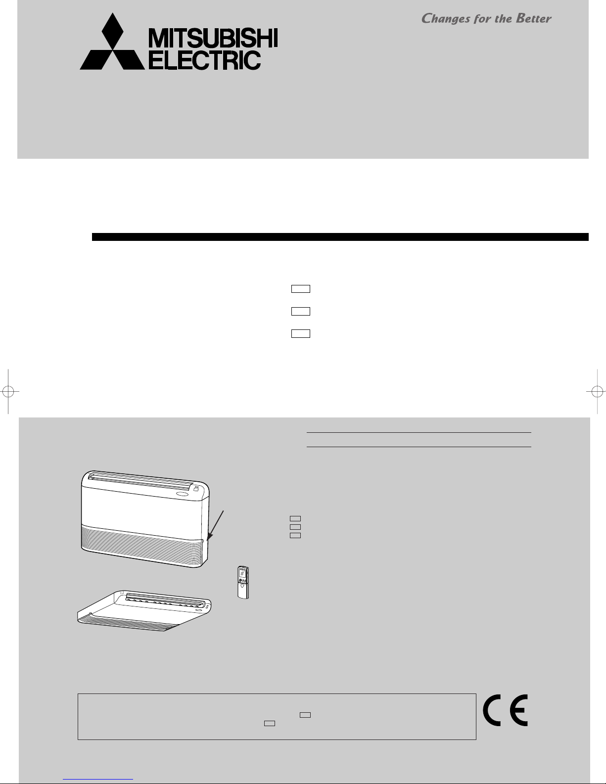
SERVICE MANUAL
(When installed on the ceiling)
(When installed on the floor)
FLOOR AND CEILING TYPE AIR CONDITIONERS
Wireless type
Models
(WH)
MCFH-GA35VBMCFH-GA50VBMCFH-GA60VB-
E1
(WH)
E1
(WH)
E1
CONTENTS
No. OB380
NOTE:
• This manual describes technical data of indoor units
• As for outdoor units MUCFH-GA35VB/GA50VB/GA60VB- , refer to the service manual OB381.
• As for outdoor units MXZ-A14/A18/A26/A32WV- , refer to the service manual OB319 REVISED
EDITION-A.
Indication of
model name
MCFH-GA35VBMCFH-GA50VBMCFH-GA60VB-
E1
1. TECHNICAL CHANGES ····································2
2. PART NAMES AND FUNCTIONS······················2
3. SPECIFICATION·················································4
4. NOISE CRITERIA CURVES·······························5
E1
5. OUTLINES AND DIMENSIONS·························6
E1
6. WIRING DIAGRAM ············································7
E1
7. REFRIGERANT SYSTEM DIAGRAM················8
8. SERVICE FUNCTIONS ······································9
9. TROUBLESHOOTING ······································11
10. DISASSEMBLY INSTRUCTIONS·····················19
11. PARTS LIST······················································21
12. OPTIONAL PARTS···········································23
E1

1
(When installed on the floor)
(When the air inlet grille is opened.)
Deodorizing filter
(gray sponge type)(option)
Air filter
Air inlet
Operation section
Air cleaning filter
(white bellows type)(option)
Front panel
Receiving section
Operation indicator lamp
Horizontal vane
Vertical vanes
Emergency
operation switch
(When installed on the ceiling)
ACCESSORIES
Item
Installation plate
Unit fixing screw
5 o 12mm
Wireless remote
controller
Remote controller
mounting hardware
Fixing screw for
3.5 o 16mm (Black)
Battery (AAA) for
remote controller
Drain hose
Drain pipe cover
Knockout cover
Screw for 4 o 10mm
2
2
1
1
2
2
1
1
1
2
Q'ty
Remote controller
TECHNICAL CHANGES
MCFH-A12WV- ➔MCFH-GA35VB-
1. Model name has been changed.
MCFH-A18WV- ➔MCFH-GA50VB-
1. Model name has been changed.
MCFH-A24WV- ➔MCFH-GA60VB-
1. Model name has been changed.
2
PART NAMES AND FUNCTIONS
E1E1
E1E1
E1E1
MCFH-GA35VB - MCFH-GA50VB - MCFH-GA60VB -
E1E1E1
INDOOR UNIT
2
MCFH-GA35VB -
ON/OFF
FAN
TOO
WARM
TOO
COOL
VANE
MODE
ECONO COOL
STOP
START
HR.
MIN.
I FEEL
COOL
HEAT
DRY
PM
CLOCK
AM
RESET CLOCK
ON/OFF
TOO
COOL
PM
AM
TOO
WARM
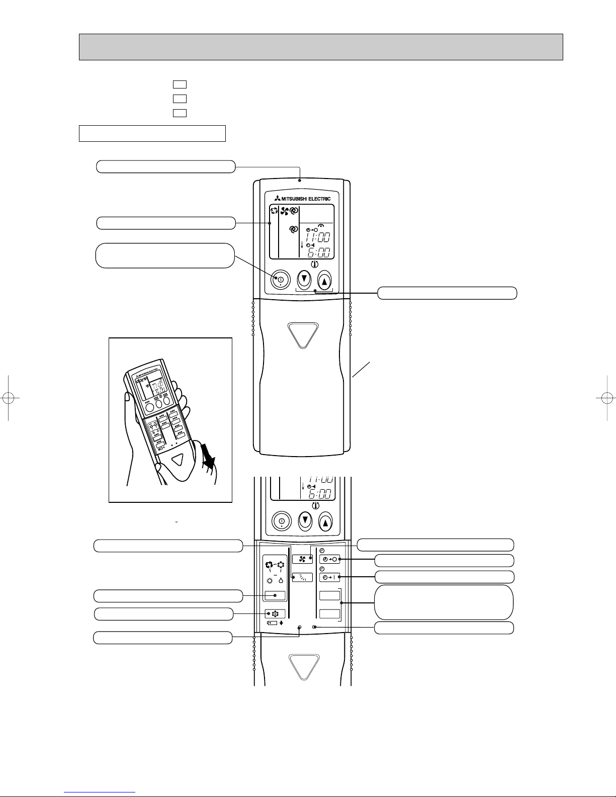
Open the front lid.
Signal transmitting section
Operation display section
OPERATE /STOP
(ON /OFF)button
TEMPERATURE buttons
OPERATION SELECT button
FAN SPEED CONTROL button
OFF-TIMER button
ON-TIMER button
RESET button
ECONO COOL button
VANE CONTROL button
CLOCK SET button
HR. button
MIN. button
(TIME SET button)
Indication of remote controller model
is on back.
MCFH-GA50VB MCFH-GA60VB -
REMOTE CONTROLLER
E1
E1
E1
3
3
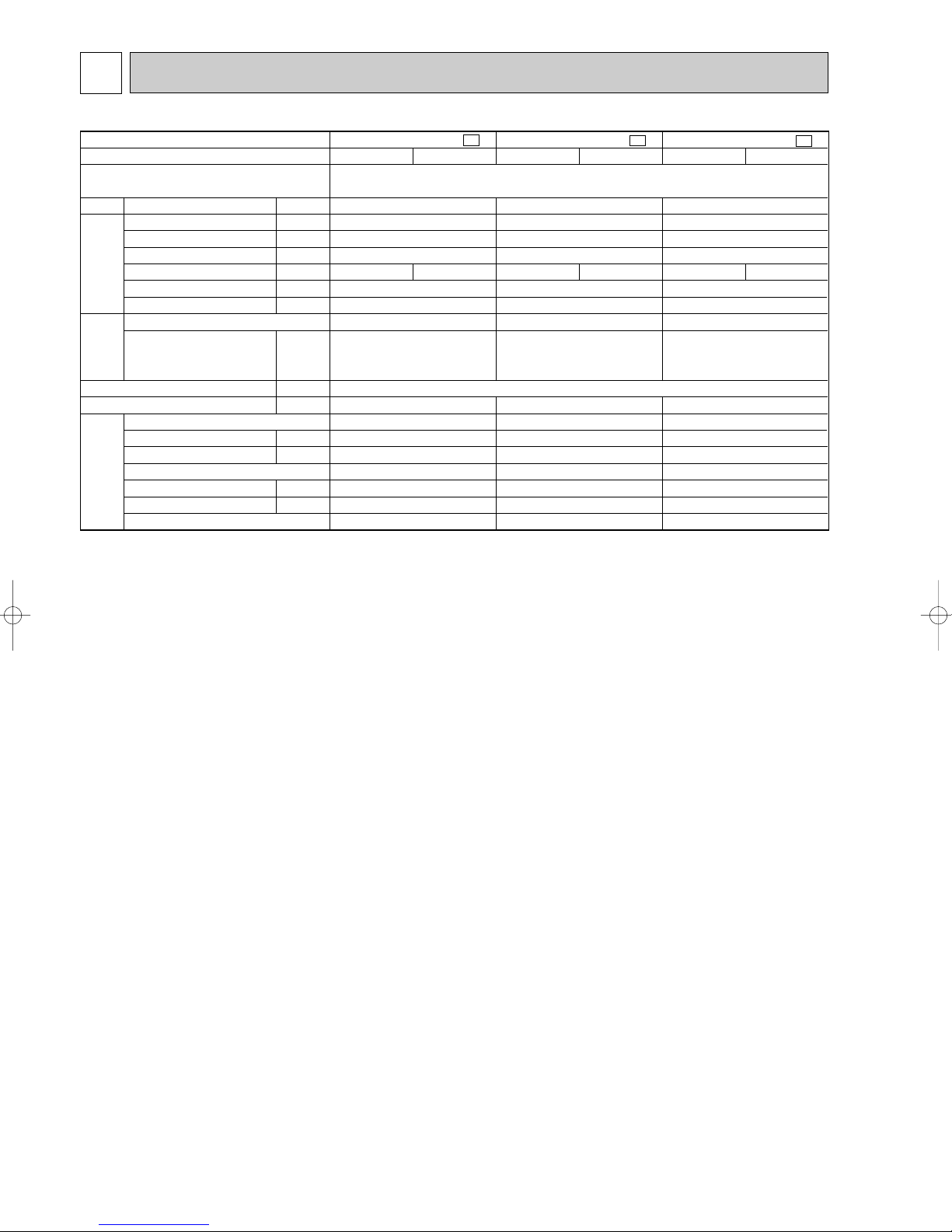
Indoor model
Function
Power supply
Air flow(High/Med.W/LowW)
Power outlet
Running current
Power input
Auxiliary heater
Power factor
Fan motor current
Model
Winding
resistance(at20:)
Dimensions WOHOD
Weight
Air direction
Sound level(High/Med.W/LowW)
Fan speed(High/Med.W/LowW)
Fan speed regulator
Thermistor RT11(at25:)
Thermistor RT12(at25:)
Remote controller model
K /h
A
A
W
A(kW)
%
A
"
mm
kg
dB
rpm
k"
k"
Electrical
data
Fan
motor
Special
remarks
Capacity
MCFH-GA35VB-
E1
MCFH-GA50VB-
E1
MCFH-GA60VB-
E1
Cooling
—
Heating
—
780/636W/492W
10
0.30
66
96
0.30
RB4V25-AC
WHT-BLK 182.2 BLK-YLW 68.9
YLW-BLU 47.5 BLU-BRN 31.5
BRN-RED 22.9
25
5
46/41W/36W
1,240/1,060/845
3
10
10
KM04M
Cooling
—
Heating
—
Single phase
230V, 50Hz
840/696W/570W
10
0.36
80
97
0.36
RB4V36-AC
WHT-BLK 82.9 BLK-YLW 65.6
YLW-BLU 36.0 BLU-BRN 27.0
BRN-RED 13.7
1100 ✕ 650 ✕ 180
25
5
48/44W/39W
1,320/1,145/960
3
10
10
KM04M
Cooling
—
Heating
—
840/744W/642W
10
0.36
80
97
0.36
RB4V36-DB
WHT-BLK 84.0 BLK-YLW 46.2
YLW-BLU 37.2 BLU-BRN 45.2
BRN-RED 13.6
25
5
48/45W/42W
1,320/1,190/1,060
3
10
10
KM04M
SPECIFICATION
NOTE: Test conditions are based on ISO 5151
Cooling : Indoor DB27°C WB19°C Heating : Indoor DB20°C WB 15°C
Outdoor DB35°C WB(24°C) Outdoor DB 7°C WB 6°C
Indoor-Outdoor piping length : 5 m
w Reference value
4
4
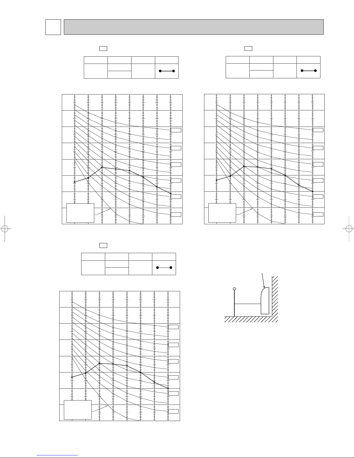
NOISE CRITERIA CURVES
MCFH-GA35VB -
E1
FAN SPEED
High
FUNCTION
COOLING
HEATING
SPL(dB
46
(A)) LINE
Test conditions,
Cooling : DB 27: WB 19:\
90
Heating : DB 20: WB 15:
80
70
60
50
40
30
APPROXIMATE
20
THRESHOLD OF
HEARING FOR
CONTINUOUS
NOISE
OCTAVE BAND SOUND PRESSURE LEVEL, dB re 0.0002 MICRO BAR
10
63 125 250 500 1000 2000 4000 8000
BAND CENTER FREQUENCIES, Hz
NC-70
NC-60
NC-50
NC-40
NC-30
NC-20
High
E1
FUNCTION
COOLING
HEATING
SPL(dB
48
(A)) LINE
MCFH-GA50VB -
FAN SPEED
Test conditions,
Cooling : DB 27: WB 19:\
90
Heating : DB 20: WB 15:
80
70
60
50
40
30
APPROXIMATE
20
THRESHOLD OF
HEARING FOR
CONTINUOUS
NOISE
OCTAVE BAND SOUND PRESSURE LEVEL, dB re 0.0002 MICRO BAR
10
63 125 250 500 1000 2000 4000 8000
BAND CENTER FREQUENCIES, Hz
NC-70
NC-60
NC-50
NC-40
NC-30
NC-20
High
E1
FUNCTION
COOLING
HEATING
SPL(dB
48
(A)) LINE
MCFH-GA60VB -
FAN SPEED
Test conditions,
Cooling : DB 27: WB 19:\
90
Heating : DB 20: WB 15:
80
70
60
50
40
30
APPROXIMATE
20
THRESHOLD OF
HEARING FOR
CONTINUOUS
NOISE
OCTAVE BAND SOUND PRESSURE LEVEL, dB re 0.0002 MICRO BAR
10
63 125 250 500 1000 2000 4000 8000
BAND CENTER FREQUENCIES, Hz
NC-70
NC-60
NC-50
NC-40
NC-30
NC-20
INDOOR UNIT
MICROPHONE
1m
1m
WALL
5
5
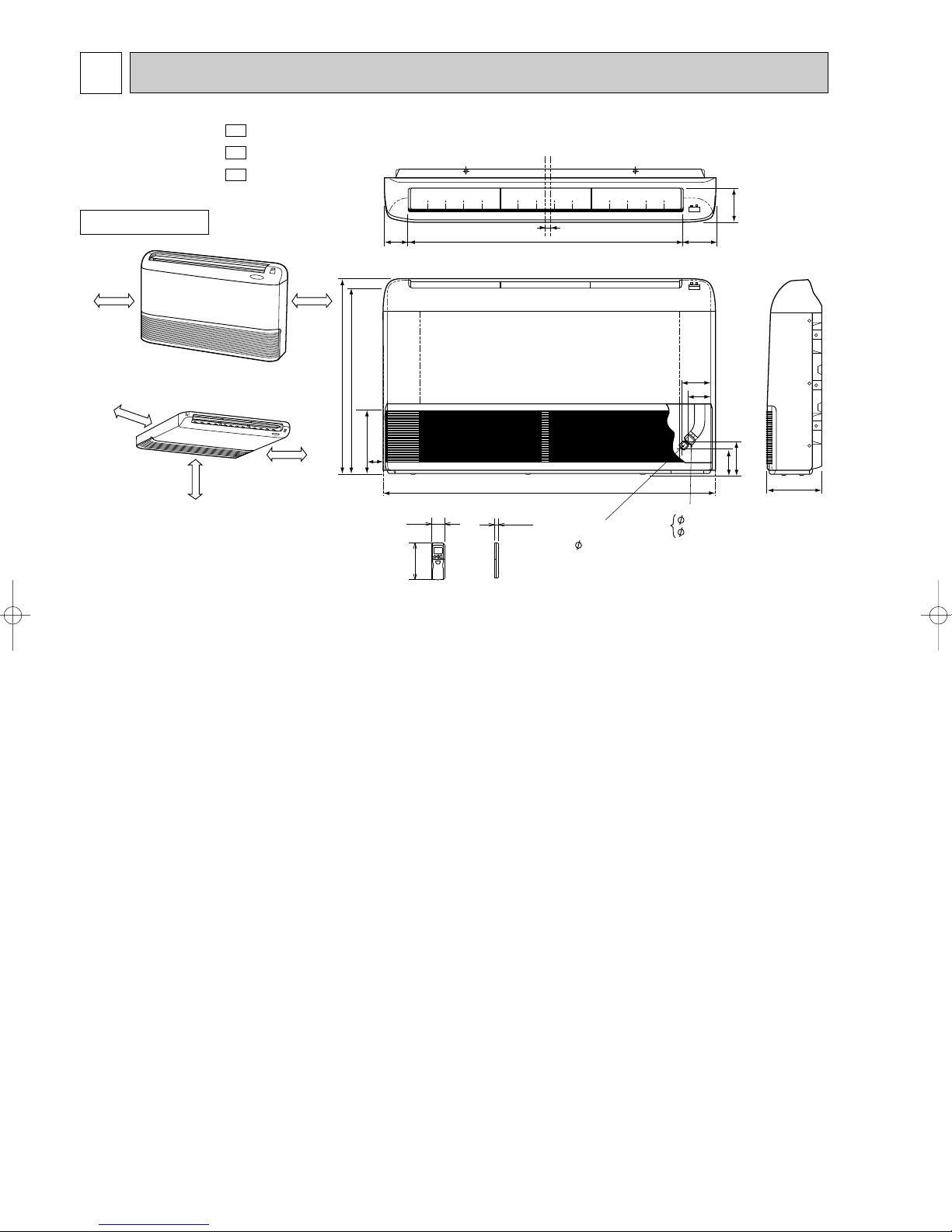
(When installed on the floor)
(When installed on the ceiling)
50cm or more
50cm or more
50cm or more
50cm or more
100cm or more
650
616.5
80.8 906 112.8
114
16
1100
93
77
113
143
180
17042.5
12.7 (MCFH-GA35/GA50VB)
15.88 (MCFH-GA60VB)
Gas line
6.35
Liquid line
Wireless remote controller
162
19
58
OUTLINES AND DIMENSIONS
MCFH-GA35VB MCFH-GA50VB MCFH-GA60VB -
INDOOR UNIT
E1
E1
E1
Unit: mm
6
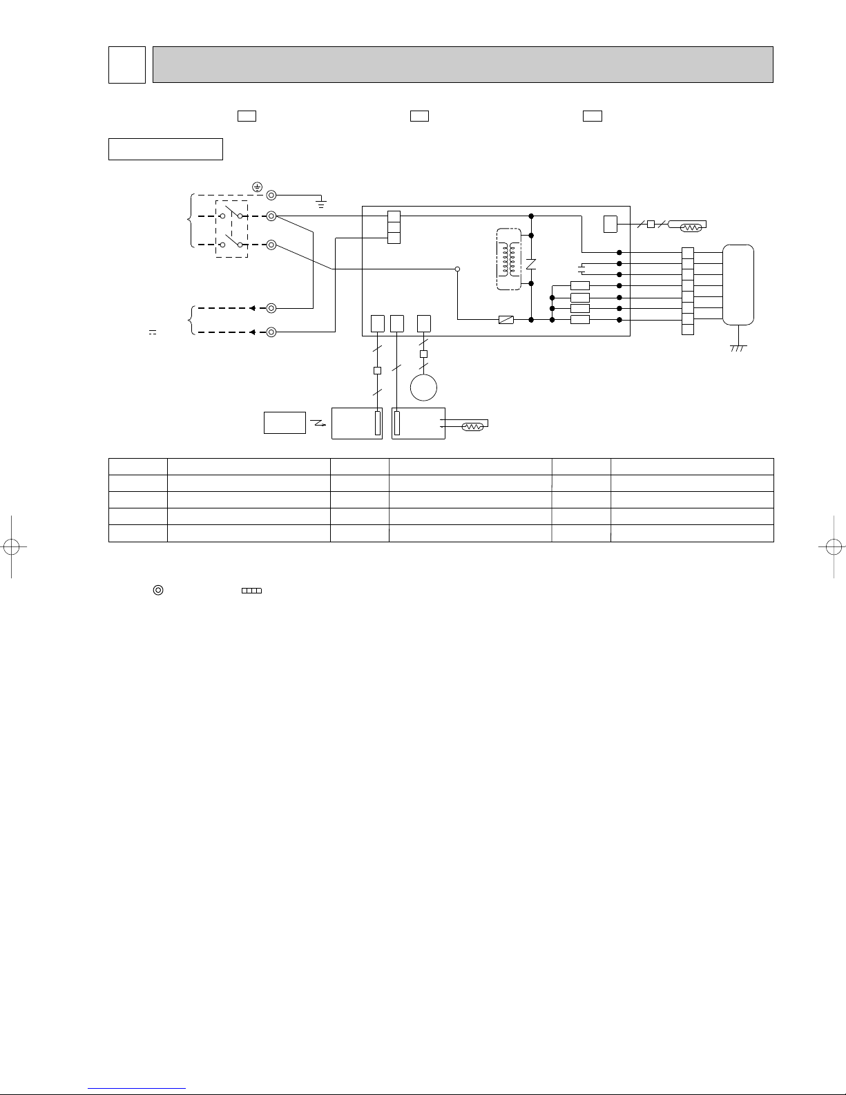
WIRING DIAGRAM6
SYMBOL
SR141~SR143
TB1, TB2
X144
SYMBOL
MV
NR11
RT11
RT12
NAME
NAME NAME
INDOOR FAN CAPACITOR
FUSE (3.15A)
DC/DC CONVERTER
INDOOR FAN MOTOR(INNER FUSE)
VANE MOTOR
VARISTOR
ROOM TEMPERATURE THERMISTOR
INDOOR COIL THERMISTOR
SOLID STATE RELAY
TERMINAL BLOCK
RELAY
1.About the outdoor side electric wiring refer to the outdoor unit electric wiring diagram for servicing.
2.Use copper conductors only. (For field wiring)
3.Symbols below indicate.
: Connector
: Terminal block
NOTES:
SYMBOL
C11
F11
HIC1
MF
MCFH-GA35VB - MCFH-GA50VB - MCFH-GA60VB -
INDOOR UNIT
POWER
SUPPLY
~/N 230V
50Hz
CIRCUIT BREAKER
TO OUTDOOR
UNIT
CONNECTING
12V
PE
N
L
N
3
MODELS WIRING DIAGRAM
TB1
GRN/YLW
TB2
BLU
REMOTE
CONTROLLER
BLU
RED
BRN
DISP/
RECEIVER
P.C.BOARD
1
2
3
CN201
CN CN CN
113 151101
5
4
MV
5
SW/THERMO
P.C.BOARD
HIC1
TAB12
F11
ELECTRONIC CONTROL P.C BOARD
6
5
RT11
C11
NR11
X144
SR143
SR142
SR141
E1E1E1
112
LDCOM
LDC11
LDC12
LDFH
LDFM
LDFL
LDFVL
CN
2
2
WHT
ORN
RED
BLK
YLW
BLU
BRN
WHT
1
ORN
2
RED
3
BLK
4
YLW
5
BLU
6
BRN
7
8
GRN/YLW
RT12
MF
7

REFRIGERANT SYSTEM DIAGRAM7
MCFH-GA35VB-
INDOOR UNIT
E1
Refrigerant pipe [12.7
(with heat insulator)
MCFH-GA50VB-
INDOOR UNIT
Unit : mm
E1
Refrigerant pipe [12.7
(with heat insulator)
Indoor
heat
exchanger
Indoor coil
thermistor
RT12
Room temperature
thermistor
RT11
Distributor
MCFH-GA60VB-
INDOOR UNIT
Flared connection
Flared connection
Refrigerant pipe
[6.35
(with heat insulator)
E1
Refrigerant pipe [15.88
(with heat insulator)
Indoor
heat
exchanger
Indoor coil
thermistor
RT12
Room temperature
thermistor
RT11
Distributor
Flared connection
Flared connection
Refrigerant pipe
[6.35
(with heat insulator)
Indoor
heat
exchanger
Indoor coil
thermistor
RT12
Room temperature
thermistor
RT11
Distributor
Flared connection
Flared connection
Refrigerant pipe
[6.35
(with heat insulator)
Refrigerant flow in cooling
Refrigerant flow in heating
8
 Loading...