


Service Manual
Electrical Wiring Diagrams

LANCER
Evolution IX
Foreword
This manual is designed to facilitate inspection and repair work relating to the electrical wiring system in the ’05 Lancer Evolution IX, and contains layout diagrams which give a three-dimensional representation of the electrical wires and connectors of the various parts of the vehicle, as well as circuit diagrams indicating the wiring design for different systems, and diagrams showing the points at which each individual component is installed.
When inspecting or repairing electrical parts, this manual should be used in conjunction with the related documents listed on the following pages, if necessary. This manual contains various different types of wiring diagrams and circuit diagrams, but it should be remembered that these may not always coincide with the exact specifications of each individual vehicle. This manual is based on the vehicle specifications as of March 2005.
Please note that future vehicles may not match the contents of this manual completely, due to changes in specifications, or the like.
The units shown in this manual are the standard international SI units. Conventional units are not included.
If you have any opinions, requests or queries regarding this manual, please write them down on the “Servicing Comment Form” on the last page, and fax them to us.
March 2005
 Mitsubishi Motor Corporation
CONTENTS
General ..........................................
Layout Diagrams ..........................
Individual part Installation
Positions .......................................
Circuit Diagrams...........................
Index ..............................................
0
1
2
3
4
This manual is printed on recycled paper.
Related Documentation
Cautionary Note regarding servicing of vehicles fitted with SRS airbags and/or seatbelts with pre-tensioner systems.
Warnings:
1.Incorrect inspection or servicing of a component part of the SRS airbag system or seatbelt pre-tensioner system, or a part relating to these systems, may cause accidental operation (deployment) of the SRS airbag or seatbelt pre-tensioners, or may cause these systems to be disabled, leading in either case the risk of serious injury.
2.If parts may be affected by heat during painting operations, then those parts must be removed in advance. This applies to the SRS-ECU, airbag modules (driver’s sear and front passenger’s seat), clock springs, front impact sensors, side impact sensors, and pre-tensioner seatbelts.
•93ºC or above : SRS-ECU, airbag modules (driver’s sear and front passenger’s seat), clock springs, front impact sensors, side impact sensors
•90ºC or above : Pre-tensioner seatbelts
3.The component parts of the SRS airbag system or seatbelt pre-tensioner system, and parts relating to these systems, must always be inspected and serviced by a Mitsubishi dealer.
4.Service personnel must read the relevant service manuals (particularly, Section 52B – SRS Airbags) carefully and thoroughly, before inspecting or servicing the component parts of the SRS airbag system or seatbelt pretensioner system, and parts relating to these systems.

0-1
SECTION 0
General Information
CONTENTS
Vehicle Identification .............................. |
0-2 |
Implementation Code ............................. |
0-2 |
How to Read the Wiring Diagrams........ |
0-2 |
Composition and Contents of Wiring Diagrams.......... |
0-2 |
How to Read Layout Diagrams................................... |
0-3 |
How to Read Circuit Diagrams ................................... |
0-4 |
Connector and Earth Markings ................................... |
0-6 |
Wire Colour Codes ..................................................... |
0-9 |
Abbreviation Symbols ................................................. |
0-9 |
0-2 GENERAL INFORMATION - VEHICLE IDENTIFICATION
VEHICLE IDENTIFICATION
Note : The [ ] symbol indicates a new model; the [ ] symbol indicates an existing model; and the [x] symbol indicates a discontinued model.
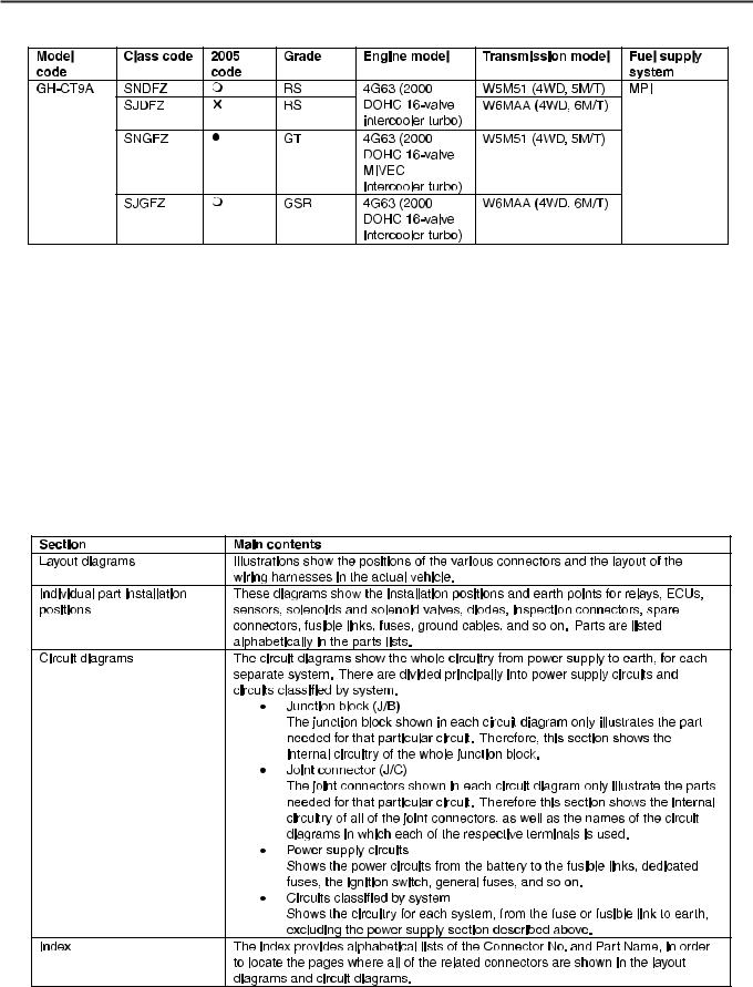
Implementation Code
GH-CT9A ; CT9A-0400001
How to Read the Wiring Diagrams
Composition and Contents of Wiring Diagrams
1.This manual contains wiring layout diagrams, individual part installation positions, circuit diagrams and an index.
2.All specifications, including those relating to optional equipment, are given in each section. Accordingly, some of the specifications may not apply to a particular vehicle.
GENERAL INFORMATION - HOW TO READ THE WIRING DIAGRAMS |
0-3 |
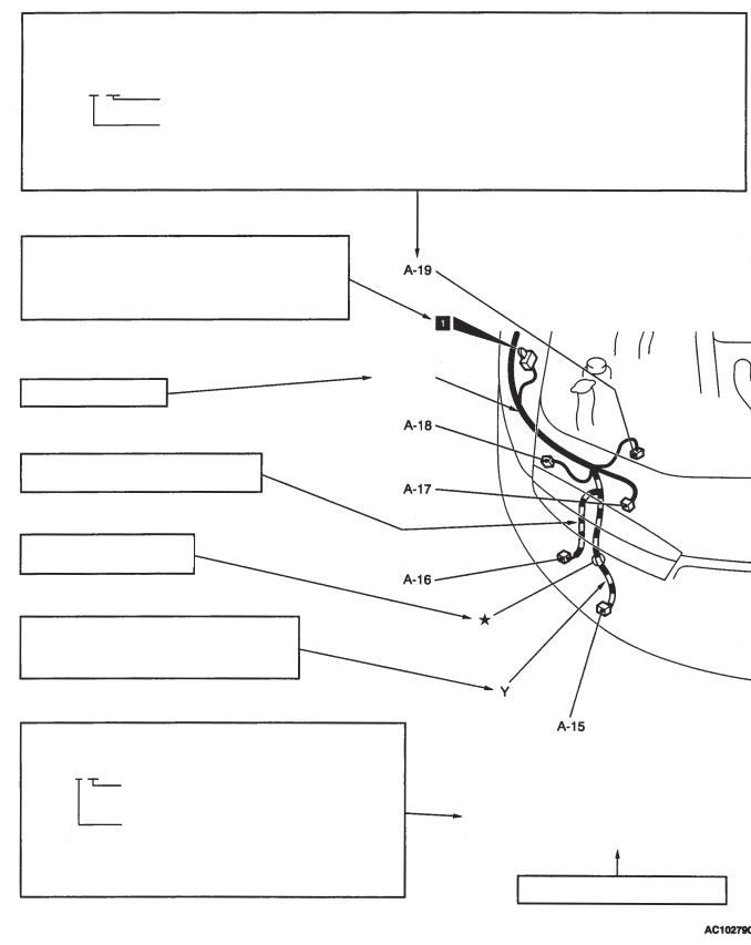
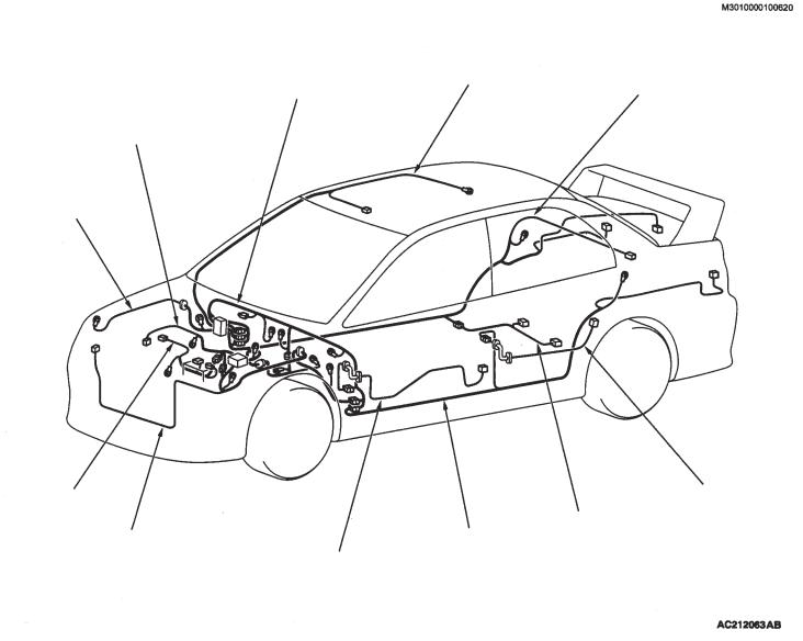
Reading Layout Diagrams
The wiring layout diagrams give a clear and simple illustration of the connector positions and the routing of the wiring harnesses at different points in the actual vehicle.
Indicates connector number.
The same connector number is used in the circuit diagrams, so that connector positions can be located easily.
The initial letter indicates the installation position of the connector, and the number that follows is the unique number for that connector. In principle, the connectors are numbered in clockwise order in each layout diagrams, starting from the top left-hand side.
Example : A – 19
Unique connector number (serial number)
Connector location code |
|
A: Engine compartment |
D: Floor / Roof |
B: Engine / Transmission |
E: Door |
C: Instrument panel |
F: Tail gate |
Indicates earth point.
The same earth numbers are used in the circuit diagrams, so earth points can be located easily. For details of earth points, refer to Section 2, "Individual Part Installation Positions – Earth".
Front
harness
Indicates name of harness
Shows section covered with corrugated tube.
The * symbol shows a standard harness mounting point.
Indicates the external colour of the harness. (Black, unless specified otherwise.)
R : Red
Y : Yellow
The number of connector pins and the connector colour (except cream colour)* are indicated, so that they can be located easily. Example : 2 – Black
Colour of connector pins
(Cream colour, unless specified
otherwise)
Number of connector pins
A-15 (2) |
Fog lamp (RH) |
|
A-16 |
(2-Black) Windshield washer motor |
|
A-17 |
(2-Black) Headlamp (RH) |
|
A-18 |
(2-Brown)Horn (LO) |
|
A-19 |
(2-Green) Dual pressure switch |
|
*^: Typical connector colours:
Black, grey, red, blue, yellow, green, brown, etc. Indicates the device to which the connector is connected.
0-4 GENERAL INFORMATION - HOW TO READ THE WIRING DIAGRAMS
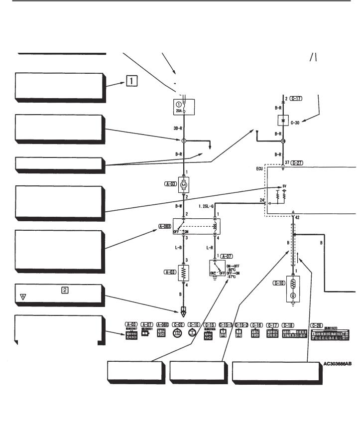
Reading Circuit Diagrams
These diagrams show the circuits for each system, from the fuse or fusible link to the earth. In principle, the power supply is shown at the top and the earth at the bottom, to make it easier to understand the flow of current in the circuit.
The circuit diagrams show a state where none of the switches, etc. are operating.
Indicates power take-out point.
Indicates that the terminal is connected via a plate inside the relay box.
Indicates connector No. The same number is used in the layout diagrams. Connector numbers shown inside a rounded box indicate connector symbols that are listed together at the bottom of the page. Connector numbers that are not shown inside a rounded box indicate components that are incorporated into the harness.
Fusible link |
Fusible link |
Each circuit diagram is divided into blocks shown on separate pages. This number indicates the block.
Relay box
Diode
Indicates the harness branch
point. This number matches the ignition branch numbers in the other
circuit diagrams.
headlights
Indicates the number of the circuit to which the branch connects.
Motor
Indicates the power supply within the control unit. If no voltage is indicated, then it is the battery voltage.
Relay
An "X" at the end of a connector number shows that it is part of the
centralized relay. For more Switch information, refer to the section
covering the Centralized Junction.
Register
Sensor
Indicates that circuit diagram continues at [A] in Block [2].
Indicates the connector symbol, listed in the order of the connector numbers in the circuit diagram.
Indicates the operating |
Indicates shield |
An upward arrow indicates that |
conditions of the coolant |
wire. |
the current flows from bottom to |
temperature switch, etc. |
|
top in the diagram. |
|
|

GENERAL INFORMATION - HOW TO READ THE WIRING DIAGRAMS |
0-5 |
Indicates input / output to and from control unit (direction of current flow).
Input Output Input/Output
Solenoid valve 1
Sensor
Indicates the connector part number given in the harness repair manual. A number in
( ) indicates the part number of the connector that corresponds to a connector symbol.
Indicates that these are the same intermediate connector.
Indicates that the diagram continues from section [A] in block [1].
Register
Indicates the terminal No.
Indicates a spare connector, if the corresponding device is not installed, due to the vehicle specifications.
If two or more connectors are connected to the same device, a broken line between parts indicates that the same connector is used.
The two-way arrow shows that current can flow downwards or upwards, under the control of the ECU.
Indicates a harness junction point where the wire changes colour or diameter.
Indicates an intersection where the wires are not connected.
Indicates an intersection where the wires are connected
Indicates the representative earth point on the vehicle body for that circuit. (This number matches that of the earth point in the layout diagrams and the diagrams of individual part installation positions.)

0-6 GENERAL INFORMATION - HOW TO READ THE WIRING DIAGRAMS
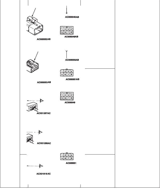
Connector / Earth Markings
The circuits contain a large number of connectors and earths, and the following system has been adopted for depicting connectors and earths in the circuit diagrams.
Fusible link
Ignition switch
Solenoid valve
Motor Sensor
Inspection connector
|
GENERAL INFORMATION - HOW TO READ THE WIRING DIAGRAMS |
0-7 |
||||
|
|
|
|
|
|
|
Item |
|
No |
Connector / Earth |
Symbol |
Details |
|
|
|
|
|
|
|
|
Terminals and |
- |
Male connector |
Male |
Different terminal symbols are |
|
|
connectors |
|
|
terminal |
used to indicate male terminals, |
||
|
|
|
|
|
which are inserted into another |
|
|
|
|
|
|
terminal, and female terminals, |
|
|
|
|
|
|
which receive other terminal. A |
|
|
|
|
|
|
connector containing male |
|
|
|
|
|
|
terminals is called a male |
|
|
|
|
|
|
connector, and a connector |
|
|
|
|
Male |
|
containing female connectors is |
|
|
|
|
|
called a female connector. The |
||
|
|
|
terminal |
|
||
|
|
|
|
connector symbol for a male |
|
|
|
|
|
|
|
|
|
|
|
|
|
|
connector has a two-line outline, |
|
|
|
|
|
|
whereas the symbol for a female |
|
|
|
|
Male connector |
Female |
connector has a single-line outline, |
|
|
|
|
terminal |
in order to distinguish them in the |
||
|
|
|
|
|
diagrams. |
|
|
|
|
|
|
|
|
|
|
|
Female |
|
|
|
|
|
terminal |
|
|
|
|
|
|
|
|
Connector |
1 |
Device |
|
The symbol shows the connector |
|
symbols |
|
|
|
used in the actual vehicle, as |
|
|
|
|
|
|
viewed from the direction of the |
|
|
|
|
|
illustration. At the connection with |
|
|
|
|
|
the device, the connector symbol |
|
|
|
|
|
on the device side, and the |
|
|
|
|
|
intermediate connector are shown |
|
|
|
|
|
by male connector symbols. |
|
|
|
|
|
Spare connectors and inspection |
|
|
|
|
|
connectors are not connected to |
|
|
2 |
Intermediate connector |
|
|
|
|
|
the device, and therefore, these |
||
|
|
|
|
|
|
|
|
|
|
|
are represented by a harness side |
|
|
|
|
|
connector symbol. Note, however, |
|
|
|
|
|
that the above does not apply to |
|
|
|
|
|
diagnosis connectors. |
|
|
|
|
|
|
3 Spare connector / Inspection connector
0-8 |
SUMMARY - OVERVIEW OF CIRCUIT DIAGRAMS |
|
No |
Connector |
4 |
connections |
|
5
6
Earths |
7 |
8
9
Connector / Earth |
Symbo |
Details |
Direct connection type
Harness connection type
Intermediate connector
Vehicle body earth
A connection between a device and a harness side connector may be achieved by direct insertion into the device (direct connection type) or by connecting to a harness connector on the device (harness connection type). These types of connection are shown differently in the diagrams.
The earth may be a vehicle body earth, a device earth, or an earth provided inside the control unit. They are depicted differently in the diagrams.
Device earth
Earth in control unit
GENERAL INFORMATION - HOW TO READ THE WIRING DIAGRAMS |
0-9 |
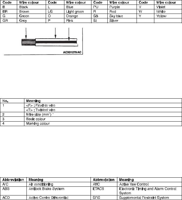
Wire Colour Codes
M3000011000154
The different wire colours are indicated by the following letter codes.
- -
Example
If a cable has two colours, the first colour code indicates the standard colour (the basic colour of the cable coating), and the second colour code indicates the marking colour.
Note :
•* : No indication : 0.5 mm2.
Cable colour in brackets indicates 0.3 mm2.
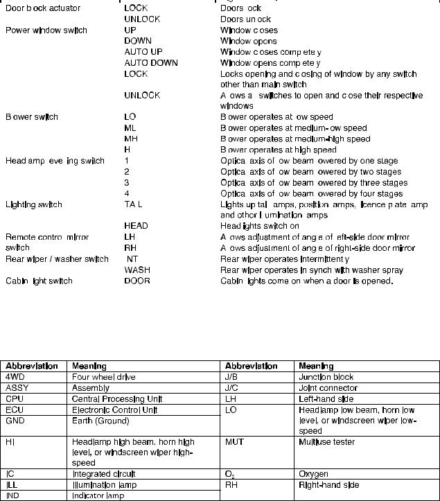
Abbreviation Symbols
The abbreviation symbols used in the wiring diagrams have the following meanings.
1. Abbreviations of System Names

0-10 GENERAL INFORMATION - HOW TO READ THE WIRING DIAGRAMS
2. Abbreviations used in internal circuits of combination meter
3. Abbreviations used in switch and relay circuits
|
|
GENERAL INFORMATION - HOW TO READ THE WIRING DIAGRAMS |
0-11 |
||||||||||||||||||||||||||||||||||
|
|
|
|
|
|
|
|
|
|
|
|
|
|
|
|
|
|
|
|
|
|
|
|
|
|
|
|
|
|
|
|
|
|
|
|
|
|
|
|
|
|
|
|
|
|
|
|
|
|
|
|
|
|
|
|
|
|
|
|
|
|
|
|
|
|
|
|
|
|
|
|
|
|
|
|
|
|
|
|
|
|
|
|
|
|
|
|
|
|
|
|
|
|
|
|
|
|
|
|
|
|
|
|
|
|
|
|
|
|
|
|
|
|
|
|
|
|
|
|
|
|
|
|
|
|
|
|
|
|
|
|
|
|
|
|
|
|
|
|
|
|
|
|
|
|
|
|
|
|
|
|
|
|
|
|
|
|
|
|
|
|
|
|
|
|
|
|
|
|
|
|
|
|
|
|
|
|
|
|
|
|
|
|
|
|
|
|
|
|
|
|
|
|
|
|
|
|
|
|
|
|
|
|
|
|
|
|
|
|
|
|
|
|
|
|
|
|
|
|
|
|
|
|
|
|
|
|
|
|
|
|
|
|
|
|
|
|
|
|
|
|
|
|
|
|
|
|
|
|
|
|
|
|
|
|
|
|
|
|
|
|
|
|
|
|
|
|
|
|
|
|
|
|
|
|
|
|
|
|
|
|
|
|
|
|
|
|
|
|
|
|
|
|
|
|
|
|
|
|
|
|
|
|
|
|
|
|
|
|
|
|
|
|
|
|
|
|
|
|
|
|
|
|
|
|
|
|
|
|
|
|
|
|
|
|
|
|
|
|
|
|
|
|
|
|
|
|
|
|
|
|
|
|
|
|
|
|
|
|
|
|
|
|
|
|
|
|
|
|
|
|
|
|
|
|
|
|
|
|
|
|
|
|
|
|
|
|
|
|
|
|
|
|
|
|
|
|
|
|
|
|
|
|
|
|
|
|
|
|
|
|
|
|
|
|
|
|
|
|
|
|
|
|
|
|
|
|
|
|
|
|
|
|
|
|
|
|
|
|
|
|
|
|
|
|
|
|
|
|
|
|
|
|
|
|
|
|
|
|
|
|
|
|
|
|
|
|
|
|
|
|
|
|
|
|
|
|
|
|
|
|
|
|
|
|
|
|
|
|
|
|
|
|
|
|
|
|
|
|
|
|
|
|
|
|
|
|
|
|
|
|
|
|
|
|
|
|
|
|
|
|
|
|
|
|
|
|
|
|
|
|
|
|
|
|
|
|
|
|
|
|
|
|
|
|
|
|
|
|
|
|
|
|
|
|
|
|
|
|
|
|
|
|
|
|
|
|
|
|
|
|
|
|
|
|
|
|
|
|
|
|
|
|
|
|
|
|
|
|
|
|
|
|
|
|
|
|
|
|
|
|
|
|
|
|
|
|
|
|
|
|
|
|
|
|
|
|
|
|
|
|
|
|
|
|
|
|
|
|
|
|
|
|
|
|
|
|
|
|
|
|
|
|
|
|
|
|
|
|
|
|
|
|
|
|
|
|
|
|
|
|
|
|
|
|
|
|
|
|
|
|
|
|
|
|
|
|
|
|
|
|
|
|
|
|
|
|
|
|
|
|
|
|
|
|
|
|
|
|
|
|
|
|
|
|
|
|
|
|
|
|
|
|
|
|
|
|
|
|
|
|
|
|
|
|
|
|
|
|
|
|
|
|
|
|
|
|
|
|
|
|
|
|
|
|
|
|
|
|
|
|
|
|
|
|
|
|
|
|
|
|
|
|
|
|
|
|
|
|
|
|
|
|
|
|
|
|
|
|
|
|
|
|
|
|
|
|
|
|
|
|
|
|
|
|
|
|
|
|
|
|
|
|
|
|
|
|
|
|
|
|
|
|
|
|
|
|
|
|
|
|
|
|
|
|
|
|
|
|
|
|
|
|
|
|
|
|
|
|
|
|
|
|
|
|
|
|
|
|
|
|
|
|
|
|
|
|
|
|
|
|
|
|
|
|
|
|
|
|
|
|
|
|
|
|
|
|
|
|
|
|
|
|
|
|
|
|
|
|
|
|
|
|
|
|
|
|
|
|
|
|
|
|
|
|
|
|
|
|
|
|
|
|
|
|
|
|
|
|
|
|
|
|
|
|
|
|
|
|
|
|
|
|
|
|
|
|
|
|
|
|
|
|
|
|
|
|
|
|
|
|
|
|
|
|
|
|
|
|
|
|
|
|
|
|
|
|
|
|
|
|
|
|
|
|
|
|
|
|
|
|
|
|
|
|
|
|
|
|
|
|
|
|
|
|
|
|
|
|
|
|
|
|
|
|
|
|
|
|
|
|
|
|
|
|
|
|
|
|
|
|
|
|
|
|
|
|
|
|
|
|
|
|
|
|
|
|
|
|
|
|
|
|
|
|
|
|
|
|
|
|
|
|
|
|
|
|
|
|
|
|
|
|
|
|
|
|
|
|
|
|
|
|
|
|
|
|
|
|
|
|
|
|
|
|
|
|
|
|
|
|
|
|
|
|
|
|
|
|
|
|
|
|
|
|
|
|
|
|
|
|
|
|
|
|
|
|
|
|
|
|
|
|
|
|
|
|
|
|
|
|
|
|
|
|
|
|
|
|
|
|
|
|
|
|
|
|
|
|
|
|
|
|
|
|
|
|
|
|
|
|
|
|
|
|
|
|
|
|
|
|
|
|
|
|
|
|
|
|
|
|
|
|
|
|
|
|
|
|
|
|
|
|
|
|
|
|
|
|
|
|
|
|
|
|
|
|
|
|
|
|
|
|
|
|
|
|
|
|
|
|
|
|
|
|
|
|
|
|
|
|
|
|
|
|
|
|
|
|
|
|
|
|
|
|
|
|
|
|
|
|
|
|
|
|
|
|
|
|
|
|
|
|
|
|
|
|
|
|
|
|
|
|
|
|
|
|
|
|
|
|
|
|
|
|
|
|
|
|
|
|
|
|
|
|
|
|
|
|
|
|
|
|
|
|
|
|
|
|
|
|
|
|
|
|
|
|
|
|
|
|
|
|
|
|
|
|
|
|
|
|
|
|
|
|
|
|
|
|
|
|
|
|
|
|
|
|
|
|
|
|
|
|
|
|
|
|
|
|
|
|
|
|
|
|
|
|
|
|
|
|
|
|
|
|
|
|
|
|
|
|
|
|
|
|
|
|
|
|
|
|
|
|
|
|
|
|
|
|
|
|
|
|
|
|
|
|
|
|
|
|
|
|
|
|
|
|
|
|
|
|
|
|
|
|
|
|
|
|
|
|
|
|
|
|
|
|
|
|
|
|
|
|
|
|
|
|
|
|
|
|
|
|
|
|
|
|
|
|
|
|
|
|
|
|
|
|
|
|
|
|
|
|
|
|
|
|
|
|
|
|
|
|
|
|
|
|
|
|
|
|
|
|
|
|
|
|
|
|
|
|
|
|
|
|
|
|
|
|
|
|
|
|
|
|
|
|
|
|
|
|
|
|
|
|
|
|
|
|
|
|
|
|
|
|
|
|
|
|
|
|
|
|
|
|
|
|
|
|
|
|
|
|
|
|
|
|
|
|
|
|
|
|
|
|
|
|
|
|
|
|
|
|
|
|
|
|
|
|
|
|
|
|
|
|
|
|
|
|
|
|
|
|
|
|
|
|
|
|
|
|
|
|
|
|
|
|
|
|
|
|
|
|
|
|
|
|
|
|
|
|
|
|
|
|
|
|
|
|
|
|
|
|
|
|
|
|
|
|
|
|
|
|
|
|
|
|
|
|
|
|
|
|
|
|
|
|
|
|
|
|
|
|
|
|
|
|
|
|
|
|
|
|
|
|
|
|
|
|
|
|
|
|
|
|
|
|
|
|
|
|
|
|
|
|
|
|
|
|
|
|
|
|
|
|
|
|
|
|
|
|
|
|
|
|
|
|
|
|
|
|
|
|
|
|
|
|
|
|
|
|
|
|
|
|
|
|
|
|
|
|
|
|
|
|
|
|
|
|
|
|
|
|
|
|
|
|
|
|
|
|
|
|
|
|
|
|
|
|
|
|
|
|
|
|
|
|
|
|
|
|
|
|
|
|
|
|
|
|
|
|
|
|
|
|
|
|
|
|
|
|
|
|
|
|
|
|
|
|
|
|
|
|
|
|
|
|
|
|
|
|
|
|
|
|
|
|
|
|
|
|
|
|
|
|
|
|
|
|
|
|
|
|
|
|
|
|
|
|
|
|
|
|
|
|
|
|
|
|
|
|
|
|
|
|
|
|
|
|
|
|
|
|
|
|
|
|
|
|
|
|
|
|
|
|
|
|
|
|
|
|
|
|
|
|
|
|
|
|
|
|
|
|
|
|
|
|
|
|
|
|
|
|
|
|
|
|
|
|
|
|
|
|
|
|
|
|
|
|
|
|
|
|
|
|
|
|
|
|
|
|
|
|
|
|
|
|
|
|
|
|
|
|
|
|
|
|
|
|
|
|
|
|
|
|
|
|
|
|
|
|
|
|
|
|
|
|
|
|
|
|
|
|
|
|
|
|
|
|
|
|
|
|
|
|
|
|
|
|
|
|
|
|
|
|
|
|
|
|
|
|
|
|
|
|
|
|
|
|
|
|
|
|
|
|
|
|
|
|
|
|
|
|
|
|
|
|
|
|
|
|
|
|
|
|
|
|
|
|
|
|
|
|
|
|
|
|
|
|
|
|
|
|
|
|
|
|
|
|
|
|
|
|
|
|
|
|
|
|
|
|
|
|
|
|
|
|
|
|
|
|
|
|
|
|
|
|
|
|
|
|
|
|
|
|
|
|
|
|
|
|
|
|
|
|
|
|
|
|
|
|
|
|
|
|
|
|
|
|
|
|
|
|
|
|
|
|
|
|
|
|
|
|
|
|
|
|
|
|
|
|
|
|
|
|
|
|
|
|
|
|
|
|
|
|
|
|
|
|
|
|
|
|
|
|
|
|
|
|
|
|
|
|
|
|
|
|
|
|
|
|
|
|
|
|
|
|
|
|
|
|
|
|
|
|
|
|
|
|
|
|
|
|
|
|
|
|
|
|
|
|
|
|
|
|
|
|
|
|
|
|
|
|
|
|
|
|
|
|
|
|
|
|
|
|
|
|
|
|
|
|
|
|
|
|
|
|
|
|
|
|
|
|
|
|
|
|
|
|
|
|
|
|
|
|
|
|
|
|
|
|
|
|
|
|
|
|
|
|
|
|
|
|
|
|
|
|
|
|
|
|
|
|
|
|
|
|
|
|
|
|
|
|
|
|
|
|
|
|
|
|
|
|
|
|
|
|
|
|
|
|
|
|
|
|
|
|
|
|
|
|
|
|
|
|
|
|
|
|
|
|
|
|
|
|
|
|
|
|
|
|
|
|
|
|
|
|
|
|
|
|
|
|
|
|
|
|
|
|
|
|
|
|
|
|
|
|
|
|
|
|
|
|
|
|
|
|
|
|
|
|
|
|
|
|
|
|
|
|
|
|
|
|
|
|
|
|
|
|
|
|
|
|
|
|
|
|
|
|
|
|
|
|
|
|
|
|
|
|
|
|
|
|
|
|
|
|
|
|
|
|
|
|
|
|
|
|
|
|
|
|
|
|
|
|
|
|
|
|
|
|
|
|
|
|
|
|
|
|
|
|
|
|
|
|
|
|
|
|
|
|
|
|
|
|
|
|
|
|
|
|
|
|
|
|
|
|
|
|
|
|
|
|
|
|
|
|
|
|
|
|
|
|
|
|
|
|
|
|
|
|
|
|
|
|
|
|
|
|
|
|
|
|
|
|
4. Other abbreviations

1-1
Section 1
Layout Diagrams
CONTENTS
General Layout Diagram |
........................1-3 |
Floor / Roof ........................................... |
1-16 |
Engine Compartment ............................. |
1-4 |
Door ....................................................... |
1-18 |
Engine / Transmission ........................... |
1-6 |
Boot Compartment ............................... |
1-20 |
Instrument Panel................................... |
1-10 |
|
|
LAYOUT DIAGRAMS - GENERAL LAYOUT DIAGRAM |
1-3 |
General Layout Diagram
Instrument |
Roof harness |
panel harness |
|
Control panel
Front harness (RH)
Battery harness
Front harness (LH) |
Floor |
|
harness (LH) |
|
Front door |
|
harness * |
Note :
1.This diagram shows the main wiring harnesses only.
2.The * symbol indicates that the harness is also fitted on the right-hand side.
Floor harness (RH)
Rear door harness *
Fuel harness
1-4 |
LAYOUT DIAGRAMS - ENGINE COMPARTMENT |
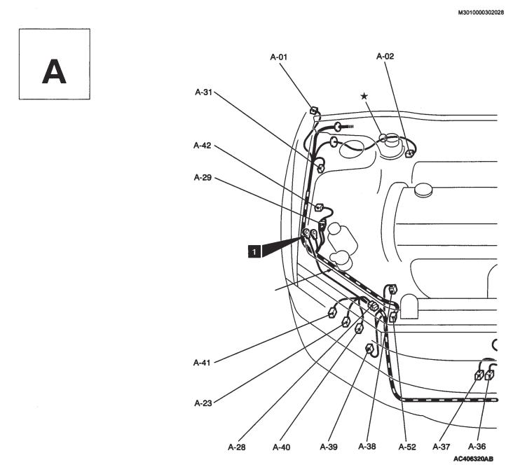
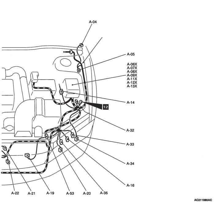
ENGINE COMPARTMENT
Connector Symbol
Front harness (RH)
A-01 (2-grey)
A-02 (2-grey)
A-04 (2-grey)
A-05 (2-black)
A-06X
A-07X
A-08X
A-09X
A-11X
A-12X
Side turn signal lamp (RH) Brake fluid level switch Side turn signal lamp (LH) Front ABS sensor (LH)
Fog lamp relay or spare connector for fog lamp relay
Horn relay
Condenser fan relay (LO) Condenser fan relay (HI) Radiator fan control relay Front ECU
A-13X |
(11) |
Front ECU |
A-14 |
(2-black) |
Junction between front harness (LH) and |
|
|
control harness |
A-16 |
(2-black) |
Headlamp (HI : LH) |
A-19 |
(3-grey) |
Radiator fan controller |
A-20 |
(1-black) |
Horn (HI) |
A-21 |
(2-brown) |
External air temperature sensor (vehicle |
|
|
fitted with fully automatic A/C) |
A-22 |
(1-black) |
Horn (LO) |
A-23 |
(2-black) |
Headlamp (HI: RH) |
A-28 |
|
Spare connector for fog lamp |
A-29 |
|
Dummy connector |
LAYOUT DIAGRAMS - ENGINE COMPARTMENT |
1-5 |
Front harness (LH)
A-31 |
(2-black) |
Front ABS sensor (RH) |
A-32 |
(4-black) |
Dummy connector |
A-33 |
(4-black) |
Headlamp ASSY (LH) (except discharge |
|
|
headlamps) |
|
(8-black) |
Headlamp ASSY (LH) (discharge |
|
|
headlamps) |
A-34 |
(2) |
Intercooler water spray motor |
A-35 |
(2-black) |
Fog lamp (LH) |
A-36 |
(2-black) |
Condenser fan motor |
A-37 |
(2-grey) |
Condenser fan motor |
A-38 |
(1-black) |
Power steering fluid pressure switch |
A-39 |
(1-black) |
A/C compressor (vehicle with manual |
|
|
A/C, fully automatic A/C) or dummy |
|
|
connector (vehicle with heater) |
A-40 |
(2-black) |
Fog lamp (RH) |
A-41 |
(4-black) |
Headlamp ASSY (RH) (except discharge |
|
|
headlamps) |
|
(8-black) |
Headlamp ASSY (RH) (discharge |
|
|
headlamps) |
A-42 |
(2-brown) |
Dual pressure switch (vehicle with |
|
|
manual A/C, fully automatic A/C) or |
|
|
dummy connector (vehicle with heater) |
A-52 |
(2-yellow) |
Front impact sensor (RH) (vehicle not |
|
|
fitted with front passenger airbag) |
A-53 |
(2-yellow) |
Front impact sensor (LH) (vehicle not |
|
|
fitted with front passenger airbag) |
1-6 |
LAYOUT DIAGRAMS - ENGINE / TRANSMISSION |
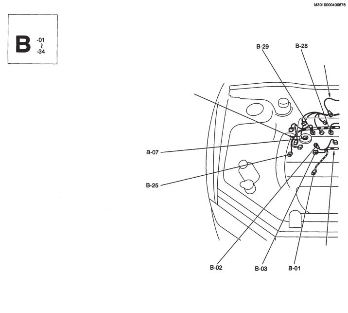
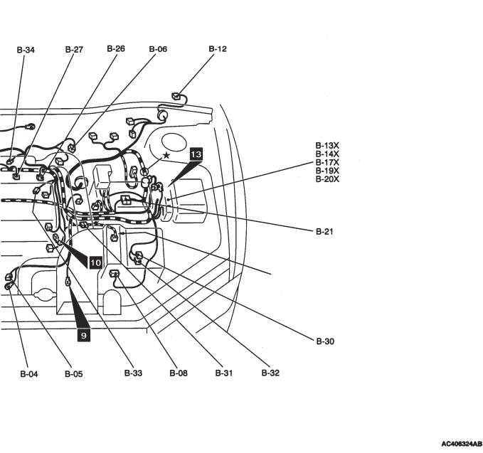
ENGINE / TRANSMISSION
Connector Symbol
Ground cable
Control harness
Battery harness
B-01 (1-black) |
Engine oil pressure switch |
B-07 |
|
B-02 |
|
Alternator |
B-08 |
B-03 (4-grey) |
Alternator |
B-12 |
|
B-04 |
|
Starter |
B-13X |
B-05 |
(1-black) |
Starter |
B-14X |
B-06 |
(4-black) |
Throttle position sensor |
B-17X |
(2-black) |
Purge control solenoid valve |
(7-black) |
Airflow sensor |
(5-grey) |
Windscreen wiper motor |
|
Engine speed detection connector |
|
Starter relay |
|
Ignition coil relay |
LAYOUT DIAGRAMS - ENGINE / TRANSMISSION |
1-7 |
Ground cable
B-19X |
(4) |
Engine control relay |
B-20X |
(4) |
A/C compressor relay |
B-21 |
(10-black) |
Control panel / battery harness junction |
B-25 |
(4-black) |
O2 sensor |
B-26 |
(2-black) |
Injector 4 |
B-27 |
(2-black) |
Injector 3 |
B-28 |
(2-black) |
Injector 2 |
B-29 (2-black) |
Injector 1 |
|
B-30 (2-grey) |
Waste gate solenoid valve 1 |
|
B-31 |
(8-black) |
Control harness / transmission harness |
|
|
junction |
B-32 |
(2-black) |
Waste gate solenoid valve 1 |
B-33 |
(3-black) |
Intake cam position sensor |
B-34 |
(2-black) |
Air temperature sensor |
1-8 |
LAYOUT DIAGRAMS - ENGINE / TRANSMISSION |
Engine / Transmission (continued)
Connector Symbol
Control harness
Battery harness
B-106 |
(2-grey) |
Knock sensor |
B-119 |
(3-grey) |
Ignition coil 2 |
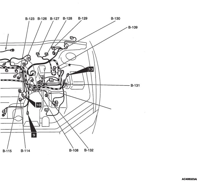
B-108 |
(2-black) |
Coolant temperature sensor |
B-122 |
(3-black) |
Crank angle sensor |
B-109 |
(34-black) |
ABS-ECU |
B-123 |
(3-grey) |
Ignition coil 1 |
B-114 |
(1-black) |
Water temperature gauge unit |
B-124 |
(2-black) |
Fuel pressure solenoid valve |
B-115 |
(3-black) |
Exhaust cam position sensor |
|
|
|
LAYOUT DIAGRAMS - ENGINE / TRANSMISSION |
1-9 |
Ground cable
Transmission harness
B-126 (6-black) |
Idle speed control servo |
B-132 |
(2-black) |
Back-up lamp switch |
|
B-127 |
(4) |
Electric pump relay |
B-133 |
(2-black) |
Secondary air control solenoid valve |
B-128 |
(4) |
Fuel pump relay 3 |
B-134 |
(2-black) |
Oil feeder control valve |
B-129 (6-black) |
Register (for injector) |
B-135 |
(3-black) |
Manifold absolute pressure sensor |
|
B-130 |
(2-black) |
Fuel pump register |
|
|
|
B-131 |
(3-black) |
Vehicle speed sensor |
|
|
|
1-10 |
LAYOUT DIAGRAMS - INSTRUMENT PANEL |
INSTRUMENT PANEL
Connector Symbol |
Front passenger side |
A/C harness
Instrument panel harness
Tweeter sub-harness
Front harness (LH)
Front door harness (LH)
Control harness
Floor harness (LH)
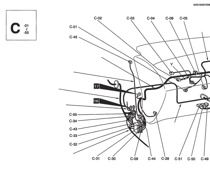
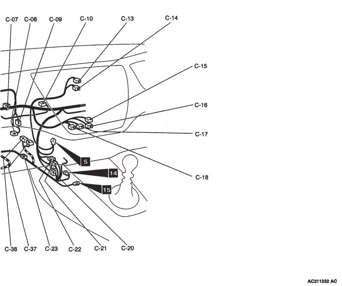
C-01 |
(4) |
Register (vehicle with heater, manual |
C-10 |
(6) |
Motor and potentiometer for blower |
|
|
A/C) |
|
|
switching damper (vehicle with fully |
C-02 (2-black) |
Front passenger airbag module (squib) |
|
|
automatic A/C) |
|
C-03 |
(7) |
Internal / External air switching damper |
C-13 |
(4) |
Clock |
|
|
motor |
C-14 |
(4) |
Hazard switch |
C-04 |
(7) |
Instrument panel harness / A/C harness |
C-15 |
(6) |
Blower switch (vehicle with heater , |
|
|
junction (vehicle with heater, manual A/C) |
|
|
manual A/C) |
|
(13) |
Instrument panel harness / A/C harness |
C-16 |
(12-black) |
Heater control unit (vehicle with heater) or |
|
|
junction (vehicle with fully automatic A/C) |
|
|
A/C ECU (vehicle with manual A/C) |
C-05 |
(2) |
Air thermo sensor (vehicle with fully |
C-17 |
(20-black) |
A/C ECU (vehicle with fully automatic |
|
|
automatic A/C) |
|
|
A/C) |
C-06 |
(13) |
J/C (5) |
C-18 |
(16-black) |
A/C ECU (vehicle with fully automatic |
C-07 (22-grey) |
J/C (5) |
|
|
A/C) |
|
C-08 |
(6) |
Motor & potentiometer for air mix door |
C-20 |
(22-blue) |
Instrument panel harness / Control |
|
|
(vehicle with fully automatic A/C) |
|
|
harness junction |
C-09 |
(2) |
Heater water temperature sensor (vehicle |
C-21 |
(10-grey) |
Instruction panel harness / Control |
|
|
with fully automatic A/C) |
|
|
harness junction |
LAYOUT DIAGRAMS - INSTRUMENT PANEL |
1-11 |
C-22 |
(25) |
Instrument panel harness / Control |
C-34 |
(16) |
Control harness / Front harness (LH) |
|
|
harness junction |
|
|
junction |
C-23 |
(33) |
J/C (6) |
C-37 (22-yellow) |
4WD-ECU |
|
C-28 |
(2) |
Blower motor (vehicle with heater, manual |
C-38 (26-yellow) |
4WD-ECU |
|
|
|
A/C) |
C-43 |
(1-grey) |
Control harness / Floor harness (LH) |
|
(6) |
Blower pulse controller (vehicle with full |
|
|
junction |
|
|
auto A/C) |
C-44 |
(2) |
Instrument panel harness / Tweeter sub- |
C-29 |
(13) |
Instrument panel harness / Floor harness |
|
|
harness junction |
|
|
(LH) junction |
C-45 |
(2) |
Tweeter (LH) |
C-30 |
(11-grey*) |
Instrument panel harness / Floor harness |
C-49 (35-grey) |
Engine ECU |
|
|
|
(LH) junction |
C-50 (28-grey) |
Engine ECU |
|
C-31 |
(25) |
Instrument panel harness / Front harness |
C-51 (30-grey) |
Engine ECU |
|
|
|
(LH) junction |
C-55 |
(2) |
Dummy connector |
C-32 |
(3) |
Instrument panel harness / Front harness |
Note : The connector marked with a * is the male-side |
||
|
|
(LH) junction |
connector. The female-side connector is coloured black. |
||
C-33 |
(16) |
Instrument panel harness / Front door |
|
|
|
|
|
harness (LH) junction |
|
|
|
1-12 |
LAYOUT DIAGRAMS - INSTRUMENT PANEL |
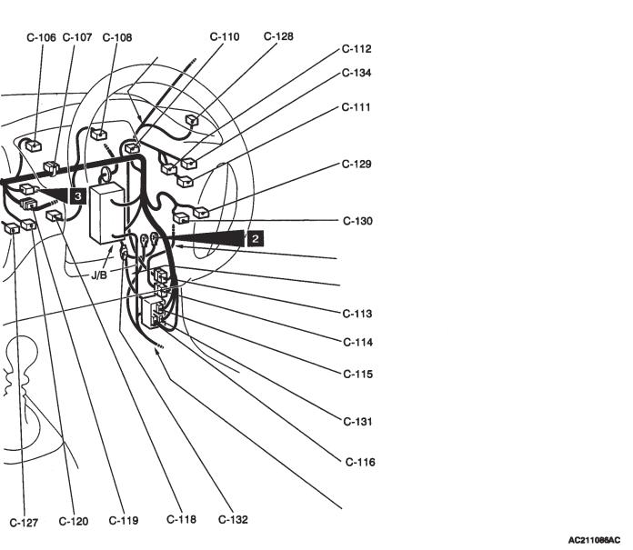
Instrument Panel (cont’d)
Connector Symbol
Driver’s side
Instrument panel harness
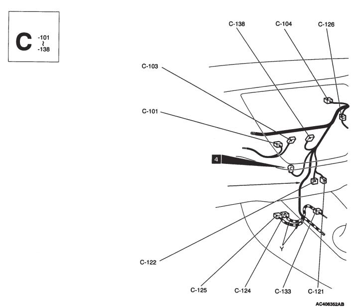
C-101 |
(1) |
Roof antenna |
C-112 |
(11-black) |
Remote control mirror switch |
C-103 |
(14) |
Spare audio connector |
C-113 |
(6) |
Instrument panel harness / Roof harness |
C-104 |
(5) |
Sunlight sensor (vehicle with full auto |
|
|
junction |
|
|
A/C) |
C-114 |
(20) |
Instrument panel harness / Front door |
C-106 |
(21) |
Combination meter |
|
|
harness (RH) junction |
C-107 |
(22-grey) |
J/C (3) |
C-115 |
(25) |
Instrument panel harness / Front harness |
C-108 |
(21-blue) |
Combination meter |
|
|
(RH) junction |
C-110 |
(22-black) |
J/C (4) |
|
|
|
C-111 |
(1) |
Spare connector for fog lamp switch |
|
|
|
LAYOUT DIAGRAMS - INSTRUMENT PANEL |
1-13 |
Roof harness
Front door harness (RH)
Front harness (RH)
Floor harness (RH)
C-116 |
(13) |
Instrument panel harness / Floor harness |
C-128 (2) |
Tweeter (RH) |
|
|
|
(RH) junction |
C-129 96) |
Fog lamp switch |
|
C-118 |
(4) |
Stop lamp switch |
C-130 (6-grey) |
Headlamp levelling switch |
|
C-119 |
(22-blue) |
J/C (2) |
C-131 (9-grey) |
Instrument panel harness / Floor harness |
|
C-120 |
(2-black) |
Cabin temperature sensor (vehicle with |
|
|
(RH) junction |
|
|
full auto A/C) |
C-132 |
(2) |
Dummy connector |
C-121 |
(12) |
Diagnosis connector |
C-133 |
(11) |
Instrument panel harness / Control |
C-122 |
(16-black) |
Diagnosis connector |
|
|
harness junction |
C-124 |
(22-yellow) |
SRS-ECU |
C-134 |
(6) |
ACD mode switch |
C-125 |
(20-yellow) |
SRS-ECU |
C-138 |
(4) |
Generic spare connector |
C-126 |
(2) |
Instrument panel harness/ Clutch switch |
|
|
|
|
|
sub-harness junction |
|
|
|
C-127 |
(2) |
Clutch switch |
|
|
|
1-14 |
LAYOUT DIAGRAMS - INSTRUMENT PANEL |
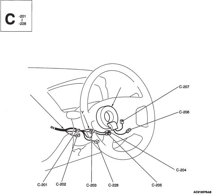
Instrument panel (cont’d)
Connector Symbol
Steering wheel
Clock spring
Instrument panel harness
C-201 (6) |
Ignition switch |
C-209 |
(14) |
Instrument panel harness / J/B junction |
|
C-202 (7) |
Key reminder switch |
C-210 |
(6) |
Instrument panel harness / J/B junction |
|
C-203 (10) |
Column switch |
C-211 |
(1-black) |
Instrument panel harness / J/B junction |
|
C-204 (4-yellow) |
Clock spring |
C-212 |
(28) |
Instrument panel harness / J/B junction |
|
C-205 |
(6) |
Clock spring |
C-213 |
(5) |
Demister relay |
C-206 |
(1) |
Horn switch |
|
|
|
C-207 |
(2) |
Driver’s airbag module (squib) |
|
|
|
C-208 |
(13) |
Instrument panel harness / J/B junction |
|
|
|
LAYOUT DIAGRAMS - INSTRUMENT PANEL |
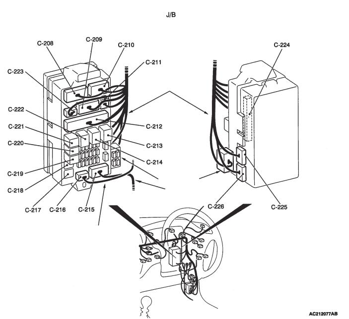
1-15 |
(Front side) |
(Rear side) |
Instrument panel harness
Dedicated fuse
Floor harness (RH)
Roof harness
C-214 (5) |
Blower relay |
C-222 (5) |
Power window relay |
||
C-215 (15) |
Floor harness (RH) / J/B junction |
C-223 (2) |
Instrument panel harness / J/B junction |
||
C-216 (3) |
Roof harness / J/B junction |
C-224 |
(20) |
ETACS-ECU |
|
C-217 (4) |
Dummy connector |
C-225 |
(24-grey) |
ETACS-ECU |
|
C-218 |
(4) |
Dummy connector |
C-226 |
(24) |
ETACS-ECU |
C-219 |
(4) |
Fuel pump relay 2 |
C-228 |
(5) |
Steer sensor |
C-220 |
(4) |
Intercooler water spray relay |
|
|
|
C-221 |
(4) |
Fuel pump relay 1 |
|
|
|
1-16 |
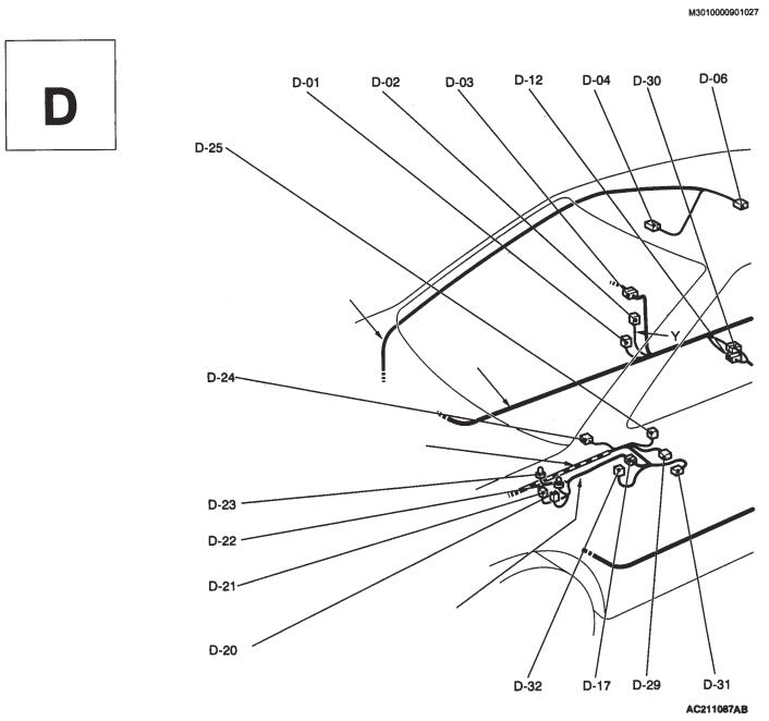
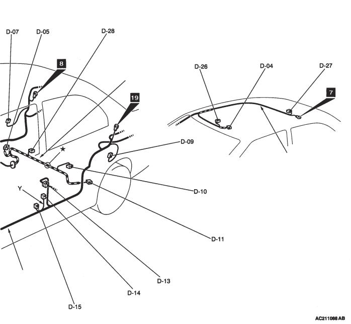
LAYOUT DIAGRAMS - FLOOR / ROOF |
FLOOR / ROOF
Connector Symbol
Roof harness
Floor harness (RH)
Instrument panel harness
Console harness
D-01 |
(3) |
Door switch (front : RH) |
D-10 |
(5-grey) |
Fuel pump and fuel gauge unit (main) |
D-02 (2-black) |
Seatbelt pre-tensioner (RH) |
D-11 |
(2-black) |
Rear ABS sensor (LH) |
|
D-03 |
(8) |
Floor harness (RH) / Rear door harness |
D-12 |
(8) |
Floor harness (RH) / Fuel harness |
|
|
(RH) junction |
|
|
junction |
D-04 |
(2) |
Front cabin lamp |
D-13 |
(8) |
Floor harness (LH) / Rear door harness |
D-05 (2-black) |
Rear ABS sensor (RH) |
|
|
(LH) junction |
|
D-06 |
(2-grey) |
Rear cabin lamp (Vehicle not fitted with |
D-14 |
(2-black) |
Seatbelt pre-tensioner (LH) |
|
|
sunroof) |
D-15 |
(3) |
Door switch (front : LH) |
D-07 |
(3) |
Door switch (rear : RH) |
|
|
|
D-09 |
(3) |
Door switch (rear : LH) |
|
|
|
LAYOUT DIAGRAMS - FLOOR / ROOF |
1-17 |
Vehicle with sunroof
Fuel harness
Roof harness
Floor harness (LH)
D-17 |
(4) |
Console harness / Instrument panel |
D-26 (6-black) |
Sunroof switch |
|
|
|
harness junction |
D-27 |
(10) |
Sunroof motor ASSY |
D-20 |
(1) |
Cigarette lighter |
D-28 |
(2) |
Fuel gauge unit (sub) |
D-21 (1-black) |
Cigarette lighter |
D-29 (3-black) |
Front/rear G sensor |
||
D-22 (2-black) |
Cigarette lighter illumination lamp |
D-30 |
(1) |
Floor harness (RH) / Fuel harness |
|
D-23 (2-black) |
Ashtray illumination lamp |
|
|
junction |
|
D-24 |
(2) |
Driver’s seatbelt switch |
D-31 (3-black) |
Lateral G sensor |
|
D-25 |
(1-black) |
Parking brake switch |
D-32 |
(6) |
Intercooler water spray switch |
 Loading...