


 Loading...
Mitsubishi LGH-15RX5, LGH-25RX5, LGH-35RX5, LGH-50RX5, LGH-65RX5 Service Manual
...
|
January 2009 No. U155 |
LOSSNAY |
|
HAND BOOK |
|
(For HONG KONG) |
FOR DEALERS |
Model: |
LGH-15RX5-E |
|
LGH-25RX5-E |
|
LGH-35RX5-E |
|
LGH-50RX5-E |
|
LGH-65RX5-E |
|
Nameplate |
|
LGH-80RX5-E |
|
LGH-100RX5-E |
|
LGH-150RX5-E |
|
LGH-200RX5-E |
Nameplate
Remote controller (Parts number is not set.)
Model: PZ-60DR-E
Filter (Parts number is not set.)
Model: PZ-25RF8-E PZ-50RF8-E PZ-80RF8-E
PZ-35RF8-E PZ-65RF8-E PZ-100RF8-E
Repair work should be performed by the manufacturer, its service agent or similarly qualified person in order to avoid hazards.
Contents
1. |
Safety precautions.................................................................... |
3 |
2. |
Specifications....................................................................... |
4-8 |
3. |
Outside dimensions............................................................ |
9-18 |
4. |
Electrical wiring diagrams ................................................ |
19-20 |
5. |
Basic circuit diagram ............................................................. |
21 |
6. |
Fundamentals of operation .............................................. |
22-44 |
7. |
Troubleshooting ............................................................... |
45-65 |
8. |
Disassembly and assembly.............................................. |
66-68 |
9. |
Parts catalog .................................................................. |
69-123 |
|
LGH-15RX5-E ............................................................... |
70-75 |
|
LGH-25RX5-E ............................................................... |
76-81 |
|
LGH-35RX5-E ............................................................... |
82-87 |
|
LGH-50RX5-E ............................................................... |
88-93 |
|
LGH-65RX5-E ............................................................... |
94-99 |
|
LGH-80RX5-E ........................................................... |
100-105 |
|
LGH-100RX5-E.......................................................... |
106-111 |
|
LGH-150RX5-E.......................................................... |
112-117 |
|
LGH-200RX5-E.......................................................... |
118-123 |
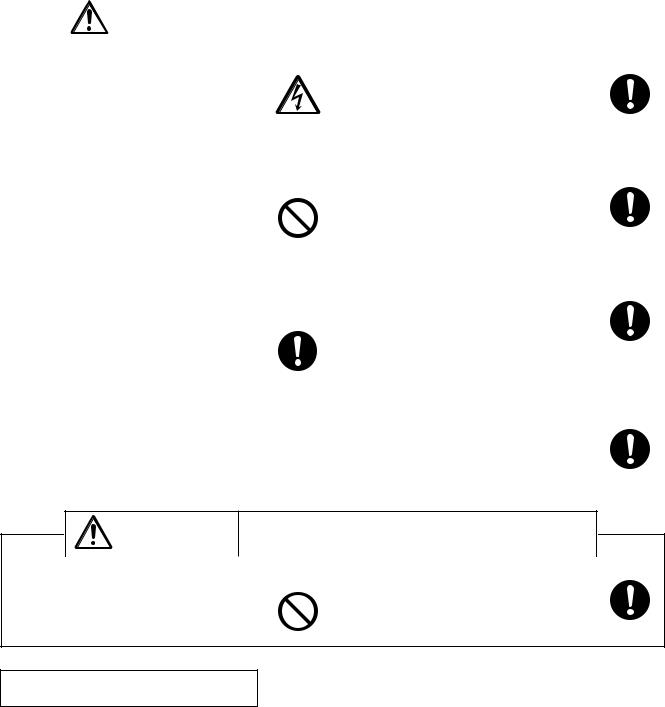
1. Safety precautions
●Please be sure to read the following safety precautions thoroughly before commencing with the maintenance work, and conduct the inspection and repair of the product in a safe manner.
●The types and levels of danger that may arise if the product is handled incorrectly are described by using the warning symbols shown below.
|
Warning |
orIncorrectdeath. handling of the product may result in serious injury |
|
|||
♦Electric |
|
|||||
|
|
|
|
|
||
shock |
|
♦Turn off the power supply |
|
|||
If you must inspect the circuitry while the |
|
Be sure to shut off the power supply isolator |
|
|||
power is on, do not touch the live parts. |
|
before disassembling the unit for repair. |
|
|||
(Failure to heed this warning may result in elec- |
Caution for |
(Failure to heed this warning may result in elec- |
Be sure to follow |
|||
tric shock.) |
tric shock.) |
|||||
electric shock |
this instruction. |
|||||
|
|
|
|
|||
♦Modification is prohibited |
|
♦Use proper parts and tools |
|
|||
Do not modify the unit. |
|
For repair, be sure to use the parts listed in the service |
||||
|
|
|
|
parts list of the applicable unit model and |
|
|
(Failure to heed this warning may result in elec- |
|
use the proper tools. |
|
|||
|
|
|||||
tric shock, fire and/or bodily injury.) |
|
|
|
|||
|
|
|
|
(Failure to heed this warning may result in elec- |
Be sure to follow |
|
|
|
|
|
tric shock, fire and/or bodily injury.) |
||
|
|
|
Prohibited |
this instruction. |
||
|
|
|
||||
♦Proper electric work |
|
♦Replace damaged and/or degraded parts |
||||
Use the electric wires designated for electric work, and |
Be sure to replace the power-supply cord and lead wire |
|||||
conduct electric work in accordance with the "Electric |
in the event that they are damaged and/or |
|
||||
Installation Engineering Standard," the "Indoor Wiring |
degraded. |
|
||||
Regulations," and the Installation Work |
|
|
|
|||
Guide. |
|
(Failure to heed this warning may result in elec- |
Be sure to follow |
|||
|
|
|
|
tric shock and/or fire.) |
||
|
|
|
|
this instruction. |
||
(Incomplete connection or wiring installation may Be sure to follow |
|
|
||||
♦Check insulation |
|
|||||
result in electric shock and/or fire.) |
this instruction. |
Be sure to measure the insulation resistance once the |
||||
|
|
|
|
repair work is complete, and turn on the power supply |
||
|
|
|
|
after verifying that an insulation resistance |
|
|
|
|
|
|
of at least 10MΩ is obtained. |
|
|
|
|
|
|
(If an insulation problem exists, it may result in |
Be sure to follow |
|
|
|
|
|
electric shock.) |
||
|
|
|
|
this instruction. |
||
|
|
|
|
|
|
|
Incorrect handling of the product may result in serious injury Caution or damage to properties including buildings and equipment.
|
|
|
|
♦Caution for bodily injury |
|
♦Wear gloves |
|
Do not conduct any work at a location |
|
Wear gloves when conducting work. |
|
where you do not have a sure footing. |
|
|
|
|
|
|
(Failure to heed this caution may result in injury |
(Failure to heed this caution may result in a fall.) |
|
to your hands from sharp metal or other edges.) |
|
|
|
Prohibited |
|
|
|
|
|
Be sure to follow this instruction.
Request during repair
•Inspect the grounding, and repair it if incomplete. Make sure that a power supply isolator is being installed, if not, install one.
●Make sure that the product operates correctly upon completion of repair. Clean the product as well as the surrounding area, and then notify the customer of the completion of repair.
—3—

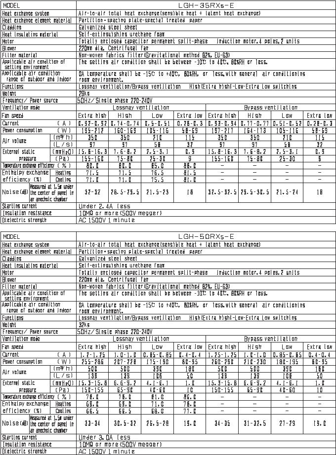
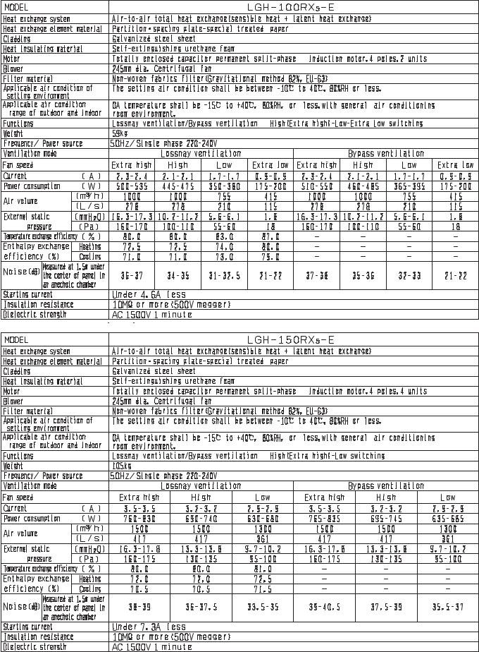
2. Specifications
—4—
—5—

—6—
—7—

—8—
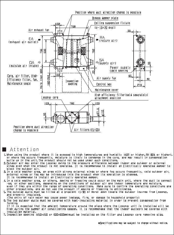
3. Outside dimensions
LGH-15RX5-E |
Unit (mm) |
—9— |
LGH-25RX5-E |
Unit (mm) |
—10— |
LGH-35RX5-E |
Unit (mm) |
—11— |

LGH-50RX5-E |
Unit (mm) |
—12— |
LGH-65RX5-E |
Unit (mm) |
—13— |
LGH-80RX5-E |
Unit (mm) |
—14— |
LGH-100RX5-E |
Unit (mm) |
—15— |
LGH-150RX5-E |
Unit (mm) |
—16— |
LGH-200RX5-E |
Unit (mm) |
—17— |
PZ-60DR-E |
Unit (mm) |
PZ-25RF8-E, PZ-35RF8-E, PZ-50RF8-E, PZ-65RF8-E, PZ-80RF8-E, PZ-100RF8-E |
Unit (mm)
—18—
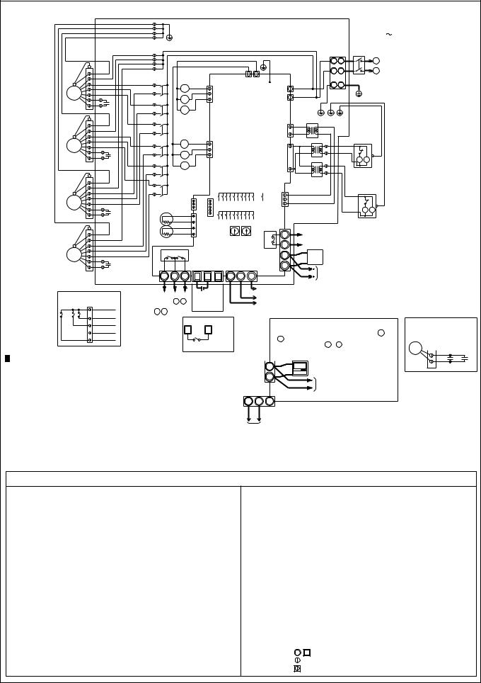
4. Electrical wiring diagrams
LGH-15RX5-E, LGH-25RX5-E, LGH-35RX5-E, LGH-50RX5-E, LGH-65RX5-E, LGH-80RX5-E, LGH-100RX5-E
|
|
|
GREEN/YELLOW |
POWER SUPPLY |
|||
|
|
BROWN |
|
|
220-240V |
50Hz |
|
|
|
RED |
|
|
|
|
|
|
|
|
|
|
TM1 |
Isolator |
|
|
|
TAB3 |
TAB5 |
|
L |
L |
|
|
BLACK |
BLUE |
|
|
|
||
|
|
TAB1 |
N |
N |
|
||
|
GREY |
CN10 |
|
|
|||
|
|
|
|
|
|
||
M2 |
YELLOW |
TAB2 |
|
|
|
|
|
|
BROWN |
PE |
|
|
|||
|
|
C |
|
|
|
||
SUPPLY |
|
|
|
|
|
||
|
|
|
|
|
|
||
|
|
|
|
|
|
|
|
FAN MOTOR |
(*2) |
|
|
|
|
|
|
|
|
|
|
BLUE |
|
|
|
|
|
|
CN1 |
RED |
|
|
|
|
ORANGE |
|
|
TR |
|
|
|
|
|
|
|
|
|
||
|
BLUE |
CN9 |
|
|
|
|
|
M1 |
WHITE |
|
|
|
|
|
|
|
|
|
|
|
|
||
EXHAUST |
C |
CN7 |
YELLOW |
|
GM |
||
FAN MOTOR |
(*2) |
|
|
|
RED |
||
|
|
|
|
|
|
|
LS |
|
|
|
|
|
|
|
|
|
|
|
BROWN |
|
|
|
|
|
|
|
|
|
CN32 |
CN16 |
|
|
SW2 |
|
CN2 |
BROWN |
|
|
|
|
|
|
|
|
|||
TH1 (OA) |
|
|
|
|
|
|
SW1 |
|
ORANGE |
|
|
|
|
|
|
|
|
||
|
|
|
|
|
|
|
|
|
|
|
|
|
|
|
|
|
|||
|
ORANGE |
|
|
|
|
|
|
CN6 |
|
|
|
|
|
|
|
|
|||
|
CN5 |
|
|
|
|
ORANGE |
|
|
|
|
|
|
|
|
|||||
|
ORANGE |
|
|
|
|
|
|
|
|
|
|
|
|
||||||
|
|
|
|
|
SW5 |
|
|
|
|
|
|
|
|
|
|
|
|
||
|
ORANGE |
|
|
|
|
|
TM4 |
Operation or Delay1 |
|
|
|
|
|
||||||
|
|
|
|
|
|
|
|
|
|
|
|
||||||||
|
ORANGE |
|
|
|
|
|
|
|
|
|
|
|
|
|
|||||
|
|
|
|
|
|
|
|
10 |
monitor output |
|
|
|
|
|
|
||||
|
|
|
|
|
|
|
|
|
|
|
|
|
|
|
|
||||
|
|
|
|
|
|
SA1 SA2 |
X10 |
MAX 240VAC 2A MIN 220VAC 100mA |
|
|
|
||||||||
TH2 (RA) |
|
|
|
|
|
|
|
|
|||||||||||
|
|
|
|
|
|
|
|
9 |
|
24VDC |
2A |
5VDC |
100mA |
|
|
|
|||
|
|
|
|
|
|
|
|
|
|
|
|
|
|
||||||
X12 X11 |
|
|
|
|
|
|
|
2 |
PZ- |
(*1) |
|
|
|
|
|
|
|||
|
|
|
|
|
|
|
|
|
|
|
|
|
|
|
|
|
|||
|
|
|
|
|
|
|
|
|
|
1 |
60DR-E |
|
|
|
|
|
|
||
TM3 |
|
|
TM2 |
|
|
TB5 |
|
|
|
|
|
2nd remote controller (Max. two remote controllers installable) |
|
|
|||||
|
|
|
|
|
|
|
|
|
|
|
|
||||||||
6 |
7 |
8 |
1 |
2 |
3 |
A |
B |
S |
|
|
|
|
|
|
|||||
|
|
|
|
2nd LOSSNAY unit (Up to max 15 units) |
|
|
|
||||||||||||
|
|
|
|
|
|
|
|
|
|
|
Transmission |
|
|
|
|
|
|
||
|
|
|
|
|
|
|
|
|
Shield Wire |
cable |
|
|
|
|
|
|
|
|
|
By-pass or Delay2 |
|
12V or 24V |
DC |
|
|
M-NET |
|
(non-polar) |
|
|
|
|
|
|
|||||
|
|
|
|
|
|
|
|
|
|
|
|
|
|||||||
monitor output 6 , 7 |
Mr.Slim |
|
|
|
transmission |
|
|
|
|
|
|
|
|
|
|
||||
Malfunction monitor |
(non-polar) |
MELANS |
cable |
|
*When the optional Remote Controller PZ-60DR-E |
(*2) LGH-100RX5 has two |
|||||||||||||
output 7 , 8 |
|
|
|
|
|
|
|
|
|
|
capacitors per motor |
||||||||
|
|
|
|
|
|
|
|
|
|
is used as the M-NET System, connect it to 1 |
|||||||||
MAX 240VAC 1A |
|
External control input |
|
|
|
|
as following drawing. |
||||||||||||
|
|
|
|
|
2 of TM4 terminal block, and connect M-NET |
||||||||||||||
24VDC |
1A |
|
1 |
|
3 |
|
|
|
|
|
M |
|
|
||||||
MIN 220VAC 100mA |
|
|
|
|
|
|
transmission wire to A , B on TB5 terminal |
|
|
||||||||||
5VDC |
100mA |
|
|
|
|
|
|
|
|
block. |
|
|
(*1) |
|
|
|
C |
C |
|
|
|
|
|
|
|
|
|
|
|
TM4 |
|
|
|
|
|
||||
|
|
|
Unchanged a-contact |
|
|
|
|
|
|
|
|
|
|
||||||
|
|
|
|
|
|
|
|
Optional Remote controller |
|
|
|
||||||||
|
|
|
|
|
|
|
2 |
|
|
|
|
|
|||||||
|
|
|
|
|
|
|
|
|
|
|
|
|
|
|
|
||||
|
|
|
|
|
|
|
|
|
|
|
|
|
(PZ-60DR-E) |
|
|
|
|
||
NOTE 1.TM1, TM2, TM3, TM4, TB5 shown |
|
|
|
|
|
|
|
|
|
|
|
CN16 |
|
|
|||||
|
|
|
|
|
|
|
1 |
|
|
2nd remote controller |
|
|
|||||||
in dotted lines are field work. |
|
|
|
|
|
|
|
|
|
|
|
|
(Unchanged a-contact) |
|
|||||
|
|
|
|
|
|
|
|
|
|
|
|
(Max. two remote controllers |
|
BROWN |
|||||
2.Isolator should be provided by the customer. |
|
|
TB5 (M-NET) |
|
|
installable) |
|
HI |
RED |
|
|||||||||
3.Be sure to connect the grounding wire. |
|
|
M-NET |
A |
B |
S |
|
|
|
|
|
LO |
ORANGE |
||||||
*Attention |
|
|
|
|
|
|
|
|
|
|
|
|
|
|
EXTRA-LO |
YELLOW |
|||
|
|
|
|
|
|
transmission |
|
Shield Wire |
|
(*1)PZ-41SLB-E and PZ-52SF-E cannot |
|||||||||
|
|
|
|
|
|
|
|
BY-PASS |
GREEN |
||||||||||
With this product, the wiring installation method will |
|
cable |
|
|
|
be used when using PZ-60DR-E. |
|||||||||||||
|
|
|
|
|
|
|
|
|
|
|
|
|
|
||||||
vary according to the design of the system. |
|
|
|
|
|
2nd or later main units |
|
|
|
|
|
|
|
|
|||||
Perform electrical installation to meet local electrical regulations. |
|
|
|
|
|
|
|
|
|
|
|
||||||||
.Always use double insulated PVC cable for the transmission cables. |
|
|
|
|
|
|
|
|
|
|
|||||||||
.Wiring work must be performed by qualified professionals. |
|
|
|
|
|
|
|
|
|
|
|
|
|||||||
.All supply circuits must be disconnected before obtaining access to the terminal devices. |
|
|
|
|
|
|
|||||||||||||
|
|
|
|
|
|
|
|
|
|
|
|
|
*Specifications may be subject to change without notice. |
||||||
Definition of Symbols
M1: |
Motor for exhaust fan |
CN1: |
Connector (Transformer primary) |
M2: |
Motor for supply fan |
CN2: |
Connector (Transformer secondary) |
C: |
Capacitor |
CN5: |
Connector (Thermistor) |
GM: |
Motor for By-pass operation |
CN6: |
Connector (Microswitch) |
LS: |
Microswitch |
CN7: |
Connector (Motor for By-pass operation) |
TH1: |
Thermistor for outside air |
TAB3: |
Tab connector(Fan motor) |
TH2: |
Thermistor for return air |
TAB5: |
Tab connector (Fan motor) |
SW1: |
Switch (Main/Sub change) |
CN9: |
Connector (Fan motor) |
SW2, 5: |
Switch (Function selection) |
CN10: |
Connector (Fan motor) |
TM1: |
Terminal block (Power supply) |
CN16: |
Connector (High/Low/Extra Low/By-pass switch) |
TM2: |
Terminal block (External control input) |
CN32: |
Connector (Remote control selection) |
TM3: |
Terminal block (Monitor output) |
SA1: |
Address setting rotary switch (10 digit) |
TM4 : |
Terminal block (Transmission cable and monitor output) |
SA2: |
Address setting rotary switch (1 digit) |
TB5 : |
Terminal block (M-NET Transmission cable) |
SYMBOL |
: Indicates terminal block. |
TAB1,TAB2: |
Connector (Power supply) |
|
: Connector. |
TR: |
Control circuit transformer |
|
: Board insertion connector or fastening |
|
connector of control board. |
||
X10,X11,X12: |
Relay contact |
|
|
|
|
—19—
LGH-150RX |
5 |
|
|
5 |
|
|
|
|
|
|
|
|
|
|
|
|
|
|
|
|
|
|
|
|
-E, LGH-200RX -E |
|
|
|
|
|
|
|
|
|
|
|
|
|
|
|
|
|
|
|
|||
|
|
|
|
|
GREEN/YELLOW |
|
|
|
|
|
|
|
|
|
|
POWER SUPPLY |
|
||||||
|
|
|
|
|
|
|
|
|
|
|
|
|
|
|
220-240V |
50Hz |
|
||||||
|
|
|
|
|
|
|
|
|
|
|
|
|
|
|
|
|
|
|
|
|
|||
|
|
|
|
|
|
|
|
|
|
|
|
|
|
|
|
|
|
TM1 |
Isolator |
|
|
|
|
|
|
|
|
|
|
|
|
|
|
|
|
BROWN |
|
|
|
|
|
L |
L |
|
|
|
|
|
|
|
|
|
|
|
|
|
|
|
|
|
|
|
|
|
|
|
|
|
|
||
|
|
|
|
|
|
|
|
|
|
|
|
RED |
|
|
|
|
|
|
N |
N |
|
|
|
|
|
|
BROWN |
|
|
|
|
|
|
|
|
|
|
|
|
|
|
|
|
|
|
||
|
|
|
x103 |
|
|
|
|
|
|
TAB3 |
TAB5 |
|
|
|
|
|
|
|
|
||||
|
|
|
BLACK |
|
|
BLACK |
|
|
|
|
BLUE |
|
PE |
|
|
|
|
||||||
|
|
|
GREY |
|
|
|
x103 |
|
|
|
|
|
|
TAB1 |
|
|
|
|
|
||||
|
|
M2 |
YELLOW |
|
|
|
GREY |
|
CN10 |
|
|
|
|
|
|
|
|
|
|
|
|||
|
|
|
|
|
x102 |
YELLOW |
|
|
|
|
|
TAB2 |
|
|
|
|
|
|
|
||||
|
|
|
|
x102 |
|
|
|
|
|
|
|
BROWN |
|
|
|
|
|
|
|||||
|
|
|
C |
|
|
|
|
|
|
|
|
|
|
|
|
|
|
||||||
|
|
SUPPLY |
|
|
|
|
|
|
|
|
|
|
|
|
|
|
|
|
|||||
|
|
|
|
|
|
|
|
|
|
|
|
|
|
|
|
|
|
|
|||||
|
|
(*2) |
|
|
|
x101 |
|
|
|
|
|
|
|
|
|
|
|
|
|
|
|
|
|
|
|
FAN MOTOR |
|
|
|
|
|
|
|
|
|
|
|
|
|
|
|
|
|
|
|
||
|
|
|
|
x101 |
|
|
|
|
|
|
|
|
|
|
|
TR1 |
|
|
|
|
|
|
|
|
|
|
RED |
|
|
|
|
|
|
|
|
|
|
|
|
|
BLUE |
|
|
|
|
|
|
|
|
|
|
|
|
|
|
|
|
|
|
|
|
CN1 |
|
|
|
|
|
|
|
|
|
|
|
|
ORANGE |
|
|
|
|
|
|
|
|
|
|
|
|
|
|
|
|
|
|
|
|
|
|
|
|
|
|
|
|
|
|
|
|
|
|
|
|
RED |
|
|
|
|
|
|
|
|
|
|
BLUE |
|
|
|
|
ORANGE |
|
|
|
|
|
|
|
|
|
|
|
|
|
||
|
|
|
x203 |
|
x203 |
|
|
|
|
|
|
|
RED |
|
BLACK |
|
|
|
|
||||
|
|
M1 |
WHITE |
|
|
|
|
|
|
|
|
|
|
|
|
|
|||||||
|
|
|
|
|
BLUE |
|
CN9 |
|
|
|
|
|
|
|
LS |
|
|
|
|||||
|
|
|
|
|
|
|
|
WHITE |
|
|
|
|
|
|
|
|
|
|
|
|
|
||
|
EXHAUST |
C |
|
|
|
x202 |
|
|
|
|
|
|
CN7 |
|
WHITE |
|
BLACK |
|
|
|
|||
|
FAN MOTOR |
(*2) |
x202 |
|
|
|
|
|
|
|
|
|
|
TR2 |
|
|
GM MG |
|
|
|
|||
|
|
x201 |
|
|
|
|
|
|
|
|
|
RED |
|
|
|
|
|
|
|||||
|
|
|
|
|
|
|
|
|
|
|
|
|
|
|
|
|
|
|
|
|
|
|
|
|
|
|
|
x201 |
|
|
|
|
|
|
|
|
|
|
|
WHITE TR3 |
|
BLACK |
|
|
|
||
|
|
|
BROWN |
|
|
|
|
|
|
|
|
|
|
|
|
|
|
|
|
||||
|
|
|
|
|
|
|
|
|
|
|
|
|
|
|
|
|
|
|
|
|
|
|
|
|
|
|
BLACK |
|
|
|
|
|
|
|
|
|
|
|
|
BROWN |
|
|
|
|
|
|
|
|
|
|
GREY |
|
|
|
CN32 |
CN16 |
|
|
|
|
|
CN2 |
BROWN |
|
|
LS |
|
|
|
||
|
|
M2 |
YELLOW |
|
|
|
|
|
SW2 |
|
|
|
|
|
|
|
|||||||
|
|
|
|
TH1 (OA) |
|
|
|
|
|
|
SW1 |
|
|
|
|
GM MG |
|
|
|
||||
|
|
|
C |
|
|
|
|
|
|
|
|
|
|
|
|
|
|
|
|
||||
|
SUPPLY |
|
|
ORANGE |
CN5 |
|
|
|
|
|
|
|
|
|
BLACK |
|
|
|
|||||
|
FAN MOTOR |
(*2) |
|
|
ORANGE |
|
|
SW5 |
|
|
|
|
|
|
|
|
|
|
|
||||
|
|
|
|
|
|
|
|
|
|
|
|
|
|
|
|
|
|
|
|||||
|
|
|
|
|
|
ORANGE |
|
|
|
|
|
|
TM4 |
|
Operation or Delay1 |
|
|
|
|
||||
|
|
|
|
|
|
|
|
|
|
|
|
|
|
|
|
|
|
||||||
|
|
|
|
|
|
ORANGE |
|
|
|
|
|
|
|
|
|
|
|
|
|
||||
|
|
|
RED |
|
|
|
|
|
|
|
|
|
10 |
monitor output |
|
|
|
|
|
||||
|
|
|
TH2 (RA) |
|
|
|
|
SA1 SA2 |
|
X10 |
|
MAX 240VAC 2A MIN 220VAC 100mA |
|
||||||||||
|
|
|
ORANGE |
|
|
|
|
|
|
|
|
9 |
|
24VDC |
2A |
5VDC |
100mA |
|
|||||
|
|
|
|
|
|
|
|
|
|
|
|
|
|
|
|
||||||||
|
|
|
BLUE |
|
X12 X11 |
|
|
|
|
|
|
|
|
|
|
(*1) |
|
|
|
|
|
||
|
|
M1 |
WHITE |
|
|
|
|
|
|
|
|
2 |
|
PZ- |
|
|
|
|
|
||||
|
|
|
|
|
|
|
|
|
|
|
|
|
|
|
|
|
|
|
|
||||
|
EXHAUST |
C |
|
|
|
|
|
|
|
|
|
|
|
1 |
|
60DR-E |
|
|
|
|
|
|
|
|
TM3 |
|
|
TM2 |
|
TB5 |
|
|
|
2nd remote controller (Max. two remote controllers installable) |
|||||||||||||
|
FAN MOTOR |
(*2) |
|
|
|
|
|
|
|
|
|
|
|
|
|
||||||||
|
|
|
6 |
7 |
8 |
1 |
2 |
3 |
A |
B |
S |
|
|
|
2nd LOSSNAY unit (Up to max 15 units) |
|
|||||||
|
|
|
|
|
|
|
|
|
|||||||||||||||
|
|
|
|
|
|
|
|
|
|
|
|
|
|
Shield Wire |
|
Transmission |
|
|
|
|
|
||
|
|
|
|
|
|
|
|
|
|
|
|
|
|
|
cable |
|
|
|
|
|
|
||
|
|
CN16 |
|
By-pass or Delay2 |
12V or 24V |
DC |
|
|
|
M-NET |
|
|
|
|
|
|
|
||||||
|
|
|
|
|
|
|
(non-polar) |
|
|
|
|
|
|
||||||||||
|
|
(Unchanged a-contact) |
monitor output |
6 , 7 |
Mr.Slim |
|
|
|
|
transmission |
|
|
|
|
|
|
|
||||||
|
|
|
BROWN |
Malfunction monitor |
(non-polar) |
|
MELANS |
cable |
|
|
|
|
|
|
|
|
|||||||
|
|
HI |
RED |
output 7 , 8 |
|
|
|
|
|
|
|
|
|
|
|
|
|
|
|
|
|
|
|
|
|
MAX 240VAC 1A |
|
External control input |
|
|
|
|
|
|
|
|
|
|
|
|
|||||||
|
|
LO |
ORANGE |
|
|
|
|
|
|
|
|
|
|
|
(*2) LGH-200RX5 has two |
||||||||
|
|
24VDC |
1A |
|
1 |
|
3 |
|
|
|
|
|
*When the optional Remote Controller PZ-60DR-E |
||||||||||
|
|
|
YELLOW |
|
|
|
|
|
|
|
|
|
capacitors per motor |
||||||||||
|
|
|
MIN 220VAC 100mA |
|
|
|
|
|
|
is used as the M-NET System, connect it to 1 |
|||||||||||||
|
|
BY-PASS |
GREEN |
|
|
|
|
|
|
|
|
as following drawing. |
|||||||||||
|
|
5VDC |
100mA |
|
|
|
|
|
|
|
|
2 |
of TM4 terminal block, and connect M-NET |
||||||||||
|
|
|
|
|
|
|
Unchanged a-contact |
|
|
|
transmission wire to |
A , |
B on TB5 terminal |
M |
|
||||||||
|
|
|
|
|
|
|
|
|
|
|
|
|
|
|
block. |
|
|
|
|
|
|
||
|
|
|
|
|
|
|
|
|
|
|
|
|
|
|
(*1) |
|
|
|
|
|
|||
NOTE 1.TM1, TM2, TM3, TM4, TB5 shown |
|
|
|
|
|
|
|
|
|
TM4 |
|
|
|
|
C |
C |
|||||||
|
|
|
|
|
|
|
|
|
|
Optional Remote controller |
|
||||||||||||
in dotted lines are field work. |
|
|
|
|
|
|
|
|
|
|
2 |
|
|
|
|
||||||||
|
|
|
|
|
|
|
|
|
|
|
(PZ-60DR-E) |
|
|
|
|
||||||||
|
|
|
|
|
|
|
|
|
|
|
|
|
|
|
|
||||||||
2.Isolator should be provided by the customer. |
|
|
|
|
|
|
|
1 |
|
2nd remote controller |
|
|
|
||||||||||
3.Be sure to connect the grounding wire. |
|
|
|
|
|
|
|
|
|
|
|
|
|
|
|||||||||
|
|
|
|
|
|
TB5 (M-NET) |
|
(Max. two remote controllers |
|
|
|||||||||||||
*Attention |
|
|
|
|
|
|
|
|
|
|
|
|
installable) |
|
|
|
|
||||||
|
|
|
|
|
|
|
|
|
M-NET |
|
A |
B |
S |
|
|
|
|
|
|
|
|
||
With this product, the wiring installation method will |
|
|
|
|
|
|
Shield Wire |
(*1)PZ-41SLB-E and PZ-52SF-E cannot |
|
||||||||||||||
vary according to the design of the system. |
|
|
|
|
|
transmission |
|
|
|
||||||||||||||
|
|
|
|
|
cable |
|
|
|
|
|
|
be used when using PZ-60DR-E. |
|
|
|||||||||
|
|
|
|
|
|
|
|
|
|
|
|
|
|
||||||||||
Perform electrical installation to meet local electrical regulations. |
|
2nd or later main units |
|
|
|
|
|
|
|
|
|||||||||||||
.Always use double insulated PVC cable for the transmission cables. |
|
|
|
|
|
|
|
|
|
|
|
||||||||||||
.Wiring work must be performed by qualified professionals. |
|
|
|
|
|
|
|
|
|
|
|
|
|
|
|
||||||||
.All supply circuits must be disconnected before obtaining access to the terminal devices. |
|
|
|
|
|
|
|||||||||||||||||
*Specifications may be subject to change without notice.
Definition of Symbols
M1: |
Motor for exhaust fan |
M2: |
Motor for supply fan |
C:Capacitor
GM: |
Motor for By-pass operation |
LS: |
Microswitch |
TH1: |
Thermistor for outside air |
TH2: |
Thermistor for return air |
SW1: |
Switch (Main/Sub change) |
SW2, 5: |
Switch (Function selection) |
TM1: |
Terminal block (Power supply) |
TM2: |
Terminal block(External control input) |
TM3: |
Terminal block (Monitor output) |
TM4: |
Terminal block |
|
(Transmission cable and monitor output) |
TB5: |
Terminal block (M-NET Transmission cable) |
TAB1,TAB2: |
Connector (Power supply) |
TR1: |
Control circuit transformer |
TR2,TR3: |
By-pass operation transformer |
X10,X11,X12: Relay contact
X101,X102,X103: Relay Supply fan speed control X201,X202,X203: Relay Exhaust fan speed control
CN1: |
Connector (Transformer primary) |
CN2: |
Connector (Transformer secondary) |
CN5: |
Connector (Thermistor) |
CN6: |
Connector(Microswitch) |
CN7: |
Connector (Motor for By-pass operation) |
CN9: |
Connector (Fan motor) |
TAB3: |
Tab connector (Fan motor) |
TAB5: |
Tab connector (Fan motor) |
CN9: |
Connector (Fan motor) |
CN10: |
Connector (Fan motor) |
CN16: |
Connector(High/Low/By-pass switch) |
CN32: |
Connector (Remote control selection) |
SA1: |
Address setting rotary switch (10 digit) |
SA2: |
Address setting rotary switch (1 digit) |
SYMBOL |
: Indicates terminal block. |
|
Board insertion connector or fastening |
|
connector of control board. |
—20—
5.Basic circuit diagram
●Circuit board diagram and check points
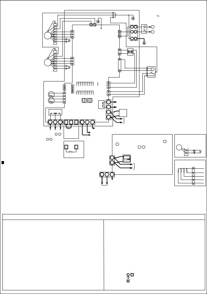
* Fan drive output voltage: Each 220 to 240 V AC
EA fan drive |
|
SA fan drive |
|
(CN9) |
|
(CN10) |
|
Extra |
|
Extra |
|
High High |
Low |
High High Low |
|
5 V DC |
|
|
|
(C6) |
|
|
|
LED 1 (Green) |
|
|
|
• Normal : unlit |
|
|
|
• During |
|
|
|
an error: blinking |
|
|
|
For damper |
|
|
|
motor drive |
|
|
|
(CN7) |
|
|
|
220 to |
|
|
|
240 V AC |
|
|
|
Damper motor |
|
|
|
position detection |
|
|
|
(CN6) *1 |
|
|
|
During Lossnay |
|
|
|
ventilation: 12 V DC |
|
|
|
During Bypass |
|
|
|
ventilation: 0 V |
|
|
|
Thermistor |
|
|
|
(RA) (OA) |
|
|
|
(CN5) |
|
|
|
LED 4 (Red) |
|
|
|
• Energized: Lit |
|
|
|
• Not |
|
|
|
energized: OFF |
|
|
|
LED 2 (Red) |
When SW5-6 is OFF |
||
When blinking, an M- |
During normal |
||
NET communication |
ventilation: 0Ω |
||
error is generated. |
During heat exchange |
||
(The number of |
ventilation: ∞Ω |
||
blinks indicates the |
When SW5-6 is ON |
||
details of the error) |
|||
During operation |
|||
|
|||
This will be lit |
and when the outdoor air |
||
steadily when there |
temperature is ≤ -5ºC to |
||
is no (registered) |
15ºC: 0Ω |
||
connection to another |
While stopped, |
||
M-NET device. |
or when the outdoor air |
||
|
temperature is ≥ 15ºC: ∞Ω |
||
|
(TM3 6,7) |
||
|
Common for SA |
|
|
|
|
|
|
|
|
||
|
fan drive |
|
|
|
|
|
|
|
|
|
|
|
(TAB5) |
|
|
|
|
|
|
|
|
|
|
|
|
|
|
|
|
Transformer |
|||||
|
|
|
|
|
|||||||
Common for EA |
|
Power supply |
|
primary (input) |
|||||||
fan drive |
|
220 to 240 V AC |
|
(CN1) |
|||||||
(TAB3) |
|
(TAB1, TAB2) |
|
220 to 240 V AC |
|||||||
|
|
|
|
|
|
|
|
|
|
|
|
|
|
|
|
|
|
|
|
|
|
|
|
|
|
|
|
|
|
|
|
GND |
|
|
|
|
|
|
|
|
|
|
|
(C5) |
|
|
|
|
|
|
|
|
|
|
|
|
|
|
|
|
|
|
|
|
|
|
|
|
|
||
|
|
|
|
|
|
|
|
Fuse |
|
||
|
|
|
|
|
|
|
|
(5 A/250 V) |
|
||
|
|
|
|
|
|
|
|
|
|
|
|
|
|
|
|
|
|
|
|
|
|
|
|
|
|
|
|
|
|
|
|
15 V DC |
|
|
|
|
|
|
|
|
|
|
|
(C3,C8) |
|
|
|
|
|
|
|
|
|
|
|
|
|
|
|
12 V DC (C4,C5)
During operation: 0Ω
When stopped: ∞Ω
(TM4 9,10)
Transformer secondary (output) (CN2)
11 to 20 V AC
During an |
|
M-NET transmission |
error : 0Ω |
|
cable (Shielded) |
Normal: ∞Ω |
|
(TB5 S) |
(TM3 7,8) |
|
|
|
|
|
For external device connections (TM2)
M-NET transmission cable (PZ-52SF-E, M-NET controller, power supply unit, and City Multi indoor unit)
(TB5 A,B)
Lossnay remote controller (PZ-60DR-E, PZ-41SLB-E) and transmission cable between Lossnay units (TM4 1, 2)
10 to 15V DC
*1: Damper position detection input is only for the LGH-15 to 100 types, and not for the LGH-150 and 200 types.
—21—
6. Fundamentals of operation
● Description of the circuit operation
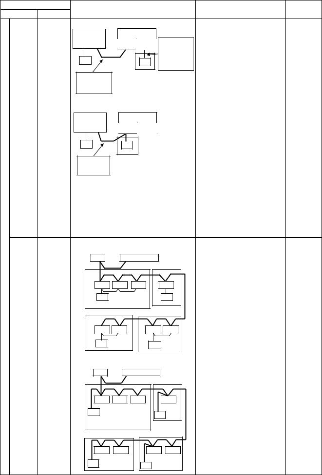
(1) System Configuration
Lossnay operates through the following system.
|
System |
|
|
|
|
|
|
|
|
System Diagram |
|
|
|
|
|
|
|
Features |
Prepared |
|||||||||||||
Classification |
Details |
|
|
|
|
|
|
|
|
|
|
|
|
|
|
|
Parts |
|||||||||||||||
|
|
|
|
|
|
|
|
|
|
|
|
|
|
|
|
|
|
|
|
|
|
|
|
|
|
|
|
|
||||
|
|
|
|
|
|
|
|
|
|
|
|
|
|
|
|
|
|
|
|
|
|
|
|
|
|
|
|
|
|
|
|
|
|
Basic |
1 Lossnay |
|
|
|
|
|
|
|
|
|
|
|
|
|
|
|
|
|
|
|
|
|
|
|
|
|
|
|
|
• One remote controller oper- |
Lossnay |
|
|
|
|
|
Lossnay |
|
|
|
|
|
|
|
|
|
|
|
|
|
|
|
|
|
|
|||||||||
|
System |
unit |
|
|
|
|
|
|
|
|
|
|
|
|
|
|
|
|
|
|
|
|
|
|
ates one Lossnay unit. |
remote |
||||||
|
|
|
|
|
|
|
|
|
|
|
|
|
|
|
|
|
|
|
|
|
|
|
|
|
|
|
|
|
||||
|
|
1 Remote |
|
|
M-NET |
Remote |
|
|
Transmission cable |
|
|
|
controller |
|||||||||||||||||||
|
|
controller |
|
|
controller |
|
|
|
|
|
(PZ-60DR- |
|||||||||||||||||||||
|
|
|
|
|
|
|
|
|
|
|
|
|
|
|
|
|
between the remote |
|
|
|
||||||||||||
|
|
|
|
|
|
|
|
|
|
|
|
|
|
|
|
|
|
|||||||||||||||
|
|
|
|
|
|
|
|
|
|
|
|
|
|
|
|
|
|
controller and Lossnay |
|
|
|
E, or PZ- |
||||||||||
|
|
|
|
|
|
|
|
|
|
|
R |
|
||||||||||||||||||||
|
|
|
|
|
|
|
|
|
|
|
|
|
|
|
|
|
|
|
|
|
|
|
|
|
41SLB-E) |
|||||||
|
|
|
Remote controller : PZ-60DR-E or PZ-41SLB-E |
|
||||||||||||||||||||||||||||
|
|
|
|
|
||||||||||||||||||||||||||||
|
|
|
|
|
|
|
|
|
|
|
|
|
|
Transmission cable terminal |
|
|
||||||||||||||||
|
|
|
|
|
|
|
|
|
|
|
|
|
|
blocks between Lossnay unit |
|
|
||||||||||||||||
|
|
|
M-NET |
: M-NET transmission cable |
|
|
||||||||||||||||||||||||||
|
|
|
|
|
|
|
|
|
|
|
|
|
|
terminal block |
|
|
|
|
|
|
|
|
|
|||||||||
|
|
|
R |
: Remote controller |
|
|
||||||||||||||||||||||||||
|
|
|
|
|
|
|
|
|
|
|
|
|
|
(PZ-60DR-E or PZ-41SLB-E) |
|
|
||||||||||||||||
|
|
|
|
|
|
|
|
|
|
|
|
|
|
|
|
|
|
|
|
|
|
|
|
|
|
|
|
|
|
|
|
|
|
Two |
1 Lossnay |
|
|
|
|
|
|
|
|
|
|
|
|
|
|
|
|
|
|
|
|
|
|
|
|
|
|
|
|
• Two remote controllers oper- |
Lossnay |
|
|
|
|
|
|
|
|
|
|
|
|
|
|
Lossnay |
|
|
|
|
|
|
|
|
||||||||||
|
remote |
unit |
|
|
|
|
|
|
|
|
|
|
|
|
|
|
|
|
|
|
|
|
|
ate one Lossnay unit. (Last |
remote |
|||||||
|
con- |
2 Remote |
|
|
|
|
|
|
|
|
|
|
M-NET |
Remote |
|
|
|
|
|
|
|
|
touch priority operation) |
controller |
||||||||
|
trollers |
controllers |
|
|
|
|
|
|
|
|
|
|
controller |
|
|
|
|
|
|
|
|
|
(PZ-60DR- |
|||||||||
|
|
|
|
|
|
|
|
|
|
|
|
|
|
|
|
|
|
|
|
|
|
|
|
|
|
|
|
|
|
|||
|
system |
|
|
|
|
|
|
|
|
|
|
|
|
|
|
|
|
|
|
|
|
|
|
|
|
|
|
|
|
|
* PZ-60DR-E and PZ-41SLB-E |
E or PZ- |
|
|
|
|
|
|
|
|
|
|
|
|
|
|
|
|
R |
|
R |
|
|
|
|
|
|
|
|||||||
|
|
|
|
|
|
|
|
|
|
|
|
|
|
|
|
|
|
|
|
|
|
|
|
|
cannot be used together. |
41SLB-E) |
||||||
|
|
|
|
|
|
|
|
|
|
|
|
|
|
|
|
|
|
|
|
|
|
|
|
|
|
|
|
|
|
|
||
|
|
|
|
|
|
|
|
|
|
|
|
|
|
|
|
|
|
|
|
|
|
|
|
|
|
|
|
|
|
|
|
|
|
Multiple |
Multiple |
|
|
|
|
|
|
|
|
|
|
|
|
|
|
|
|
|
|
|
|
|
|
|
|
|
|
|
|
• A maximum of 15 Lossnay |
Lossnay |
|
|
|
Lossnay |
|
|
Lossnay |
|
|
|
Lossnay |
|
|||||||||||||||||||||
|
units |
Lossnay |
|
|
|
|
|
|
|
units can be operated by a |
remote |
|||||||||||||||||||||
|
|
|
|
|
|
|
|
|
|
|
|
|
|
|
|
|
|
|
|
|
|
|
|
|
|
|
|
|
||||
|
system |
units |
|
M-NET |
Remote |
|
M-NET |
Remote |
|
M-NET |
Remote |
|
single remote controller. |
controller |
||||||||||||||||||
|
|
controller |
|
controller |
|
controller |
|
|||||||||||||||||||||||||
|
|
|
|
|
|
|
|
|
|
|
|
|
|
|
|
|
|
|
|
|
|
|
|
|
|
|
|
|
|
|
(Group operation) |
(PZ-60DR- |
|
|
|
|
|
|
|
|
|
|
|
|
|
|
|
|
|
|
|
|
|
|
|
|
|
|
|
|
|
|
|
||
|
|
|
|
|
|
|
|
|
|
|
|
|
|
|
|
|
|
|
|
|
|
|
|
|
|
|
|
|
|
• All units will operate in the |
E or PZ- |
|
System |
|
|
|
|
|
|
|
|
|
R |
|
|
|
|
|
|
|
|
|
|
|
|
|
|
|
|
|
|
||||
|
|
|
|
|
|
|
|
|
|
|
|
|
|
|
|
|
|
|
|
|
|
|
|
|
|
|
|
|
|
same mode. |
41SLB-E) |
|
|
|
|
|
|
|
|
|
|
|
|
|
|
|
|
|
|
|
|
|
|
|
|
|
|
|
|
|
|
|
|
||
|
|
|
|
|
Remote controller (PZ-60DR-E,or PZ-41SLB-E) |
|
|
|||||||||||||||||||||||||
|
|
|
|
|
|
|
|
|
|
|
|
|
|
|
|
|
|
|
|
|
|
|
|
|
|
|
|
|
|
|
|
|
Basic |
Systems |
Level sig- |
|
|
|
|
|
|
|
|
|
|
|
|
|
|
|
|
|
|
|
|
|
|
|
|
|
|
|
|
• Lossnay is started/stopped |
|
interlock |
nal output |
|
|
External device |
|
|
|
Lossnay |
|
by a signal (*1) from an |
|
|||||||||||||||||||||
|
|
|
|
|
|
|
|
|
|
|||||||||||||||||||||||
ed with |
device |
|
|
(Other manufacturer’s |
|
|
|
|
|
|
|
|
|
|
|
|
|
|
external device. |
|
||||||||||||
|
|
|
|
M-NET |
Remote |
|
|
|
|
|
||||||||||||||||||||||
|
|
PAC etc.) |
|
|
|
|
|
|
|
|
|
|||||||||||||||||||||
|
external |
(other |
|
|
|
|
|
|
|
|
|
controller |
|
• Having a remote control per- |
|
|||||||||||||||||
|
|
|
|
|
|
|
|
|
|
|
|
|
|
|
|
|
|
|
|
|
|
|
|
|
|
|
|
|
|
|||
|
|
|
|
|
|
|
|
|
|
|
|
|
|
|
|
|
|
|
|
|
|
|
|
|
|
|
|
|
|
|||
|
device |
manufac- |
|
|
Level (pulse) signal |
|
|
|
|
|
|
|
|
|
|
|
|
|
mits last touch priority opera- |
|
||||||||||||
|
(air con- |
turer's |
|
|
|
|
|
|
|
|
|
|
|
|
|
|
|
tion with the external device |
|
|||||||||||||
|
dition- |
PAC, etc.) |
|
|
Output device |
|
|
|
|
|
|
|
|
|
|
|
|
|
and the remote controller. |
— |
||||||||||||
|
ing |
or pulse |
|
|
|
|
|
|
|
|
|
|
|
|
|
|
|
|
|
|
|
|
|
|
|
|
|
|
|
|
• A maximum of 15 Lossnay |
|
|
|
|
|
|
|
|
|
|
|
|
|
|
|
|
|
|
|
|
|
|
|
R |
|
|||||||||
|
units) |
signal out- |
|
|
|
|
|
|
|
|
|
|
|
|
|
|
|
|
|
|
|
|
|
|
|
|
|
|
|
|
units can be operated. |
|
|
|
put device |
|
|
|
|
|
|
|
|
|
|
|
|
|
|
|
|
|
|
|
|
|
|
|
|
|
|
|
|
*1: An uncharged a-contact, |
|
|
|
(building |
|
|
Remote controller (PZ-60DR-E, or PZ-41SLB-E) |
12 V DC or 24 V DC level |
|
|||||||||||||||||||||||||
|
|
control |
|
|
(Operation without a remote controller is also |
signal, or an uncharged a- |
|
|||||||||||||||||||||||||
|
|
system, |
|
|
possible.) |
|
|
|
|
|
|
|
|
|
|
|
|
|
|
|
|
|
|
contact, 12 V DC or 24 V |
|
|||||||
|
|
|
|
|
|
|
|
|
|
|
|
|
|
|
|
|
|
|
|
|
|
|
|
|
|
|
|
|
|
|
||
|
|
etc.) |
|
|
|
|
|
|
|
|
|
|
|
|
|
|
|
|
|
|
|
|
|
|
|
|
|
|
|
|
DC pulse signal. |
|
|
|
|
|
|
|
|
|
|
|
|
|
|
|
|
|
|
|
|
|
|
|
|
|
|
|
|
|
|
|
|
|
|
|
|
Mr. Slim |
|
|
|
|
|
|
|
|
|
|
|
|
|
|
|
|
|
|
|
|
|
|
|
|
|
|
|
|
• Lossnay can be |
|
|
|
(A-control |
|
|
|
Mr. Slim |
|
|
|
|
|
|
|
|
Lossnay |
|
|
|
started/stopped by an A-con- |
|
||||||||||||
|
|
|
|
|
|
|
|
|
|
|
|
|
|
|
||||||||||||||||||
|
|
|
|
|
|
|
|
|
|
|
|
|
|
|
|
|
|
|
|
|
|
|
||||||||||
|
|
or K-con- |
|
|
|
indoor unit |
|
|
|
|
|
|
|
M-NET |
Remote |
|
|
|
trol remote controller or a K- |
|
||||||||||||
|
|
trol |
|
|
|
|
|
|
|
|
|
|
|
|
|
|
|
|
|
controller |
|
|
|
control remote controller. |
|
|||||||
|
|
|
|
|
|
|
|
Mr. Slim |
|
|
|
|
|
|
|
|
|
|
|
|
|
|
||||||||||
|
|
remote |
|
|
|
|
|
|
Mr. Slim-Lossnay |
• Lossnay High or Low fan |
|
|||||||||||||||||||||
|
|
con- |
|
|
|
|
|
|
Lossnay |
connection cable |
speed can be selected from |
|
||||||||||||||||||||
|
|
|
|
|
|
|
|
interlocked |
|
|||||||||||||||||||||||
|
|
troller) |
|
|
|
|
|
|
(Included parts with |
the A-control remote controller. |
— |
|||||||||||||||||||||
|
|
|
|
|
|
|
|
signal |
|
|
|
|
|
|
Lossnay) |
|||||||||||||||||
|
|
|
|
|
|
A,K |
|
|
|
|
|
|
|
|
|
|
|
|
|
|
|
|
|
|
|
|
|
|
• Lossnay stand-alone opera- |
|
||
|
|
|
|
|
|
|
|
|
|
|
|
|
|
|
|
|
|
|
|
|
|
|
|
|
|
|
|
|
|
|
tion is permitted from the A- |
|
|
|
|
|
|
A-control or K- |
|
|
|
|
|
|
|
|
|
|
|
|
|
|
|||||||||||||
|
|
|
|
|
|
|
|
|
|
|
|
|
|
|
|
|
|
control remote controller. |
|
|||||||||||||
|
|
|
|
|
control remote |
|
|
|
|
|
|
|
|
|
|
|
|
|
|
|||||||||||||
|
|
|
|
|
controller |
|
|
|
|
|
|
|
|
|
|
|
|
|
|
|
|
|
|
|
|
|||||||
|
|
|
|
|
|
|
|
|
|
|
|
|
|
|
|
|
|
|
|
|
|
|
|
|
|
|
|
|
|
|
* Neither PZ-60DR-E nor PZ- |
|
|
|
|
|
|
|
|
|
|
|
|
|
|
|
|
|
|
|
|
|
|
|
|
|
|
|
|
|
|
|
|
41SLB-E can be used. |
|
|
|
|
|
|
|
|
|
|
|
|
|
|
|
|
|
|
|
|
|
|
|
|
|
|
|
|
|
|
|
|
|
|
|
|
|
|
|
|
|
|
|
|
|
|
|
|
|
|
|
|
|
|
— 22— |
|
|
||||||||||
|
System |
|
System Diagram |
|
|
Features |
Prepared |
|||
Classification |
Details |
|
|
|
Parts |
|||||
|
|
|
|
|
|
|
||||
|
Systems Mitsubishi |
When using PZ-60DR-E |
|
|
• Can be interlocked with a |
|
||||
|
interlock |
City Multi |
City Multi |
|
|
Lossnay |
|
|
maximum of 16 air condition- |
|
|
ed with |
air condi- |
|
|
|
|
ing units. |
|
||
|
Indoor unit |
|
|
Remote |
Transmission |
|
||||
|
external |
tioner |
|
|
• Lossnay can be |
|
||||
|
|
|
M-NET controller |
cable between |
|
|||||
|
device |
(MA |
|
|
|
|
the remote |
started/stopped, and |
|
|
|
(air con- |
remote |
MA |
|
|
R1 |
controller and |
switched between High and |
|
|
|
dition- |
controller |
|
|
|
|
Lossnay |
Low fan speed by an air con- |
|
|
|
|
|
|
|
|
|
|
|||
|
ing |
or ME |
M-NET |
|
Lossnay remote controller |
ditioner remote controller. |
|
|||
|
units) |
remote |
transmission |
|
(PZ-60DR-E) |
|
|
• Lossnay stand-alone opera- |
|
|
|
|
(Operation without a remote |
|
|||||||
|
|
controller) |
cable |
|
tion is permitted from an air |
|
||||
|
|
|
|
controller is also possible.) |
|
|||||
|
|
|
When using PZ-52SF-E |
|
|
conditioner remote con- |
|
|||
|
|
|
|
|
troller. |
|
||||
|
|
|
City Multi |
|
|
Lossnay |
|
|
• Having PZ-60DR-E or PZ- |
|
|
|
|
|
|
|
|
|
52SF-E, last touch priority |
|
|
|
|
|
indoorIndoorunit |
|
M-NET Remote |
|
|
— |
||
|
|
|
|
|
|
operation is permitted with |
||||
|
|
|
|
|
|
controller |
|
|
|
|
|
|
|
MA |
|
R2 |
|
|
the air conditioner remote |
|
|
|
|
|
|
|
|
controller and the Lossnay |
|
|||
|
|
|
|
|
|
|
|
|||
|
|
|
M-NET |
|
Remote controller for M-NET |
remote controller. |
|
|||
|
|
|
|
|
|
|||||
|
|
|
transmission |
|
(PZ-52SF-E) |
|
|
*1: PZ-41SLB-E cannot be |
|
|
|
|
|
cable |
|
(Operation without a remote |
|
||||
|
|
|
|
|
controller is also possible.) |
used in this system. |
|
|||
|
|
|
Remote controller : Terminal block for trans- |
*2: PZ-60DR-E and PZ-52SF-E |
|
|||||
|
|
|
|
|
mission cable between PZ- |
cannot be used together. |
|
|||
|
|
|
|
|
60DR-E and Lossnay |
|
|
|||
|
|
|
M-NET |
: M-NET transmission cable |
|
|
||||
|
|
|
|
|
terminal block |
|
|
|
|
|
Control |
|
|
R1 |
: PZ-60DR-E |
|
|
|
|
||
|
|
R2 |
: PZ-52SF-E |
|
|
|
|
|||
Central |
Central/in |
When using PZ-60DR-E |
|
|
• Lossnay batch/independent |
• Lossnay |
||||
NET |
control |
depen- |
System controller |
Power supply unit |
|
|
(group) control permitted by |
remote |
||
system |
dent con- |
SC |
|
Power supply |
|
|
system controller. |
controller |
||
M- |
for |
trol of |
|
|
|
Group 1 |
|
Group 2 |
• Operation of Lossnay within |
(PZ-60DR- |
|
Lossnay |
multiple |
|
|
|
|
|
|
a group is permitted by a |
E or PZ- |
|
only |
Lossnay |
Lossnay |
Lossnay |
Lossnay |
Lossnay |
Lossnay remote controller. |
52SF-E) |
||
|
|
units |
(PZ-60DR-E or PZ-52SF-E) |
• Centralized |
||||||
|
|
|
|
|
|
|
|
|||
|
|
|
R1 |
|
|
|
|
R1 |
• One group of a maximum of |
controllers |
|
|
|
Remote controller (PZ-60DR-E) |
|
|
16 Lossnay units can be |
(G-50A), |
|||
|
|
|
Group 3 |
Group 4 |
operated. |
(PAC- |
||||
|
|
|
|
|
|
|
|
|
• Number of Lossnay control |
SF44SRA), |
|
|
|
Lossnay |
Lossnay |
Lossnay |
|
Lossnay |
units |
(PAC- |
|
|
|
|
|
|
|
|
|
|
Centralized controller (AG- |
YT40ANR |
|
|
|
R1 |
|
|
R1 |
|
|
150A) : 50 units/50 groups |
A), and |
|
|
|
When using PZ-52SF-E |
|
|
ON/OFF remote controller |
(AG-150A) |
|||
|
|
|
|
|
(PAC-YT40ANRA) : 50 |
• Power sup- |
||||
|
|
|
M-NET controller |
Power supply unit |
|
units/16 groups |
ply units |
|||
|
|
|
SC |
|
Power supply |
|
Group 2 |
System remote controller |
(PAC- |
|
|
|
|
|
|
|
Group 1 |
|
(PAC-SF44SRA) : 50 |
SC50KUA), |
|
|
|
|
|
|
|
|
|
|
units/50 groups |
(PAC- |
|
|
|
Lossnay |
Lossnay |
Lossnay |
|
Lossnay |
|
SF46EPA), |
|
|
|
|
|
|
|
|
|
|
*1: The remote controller (PZ- |
and (PAC- |
|
|
|
R2 |
|
|
R2 |
41SLB-E) cannot be used |
SC51KUA) |
||
|
|
|
|
|
|
in this system. |
|
|||
|
|
|
Remote controller for M-NET |
|
|
|
||||
|
|
|
(PZ-52SF-E) |
|
|
|
*2: PZ-60DR-E and PZ-52SF-E |
|
||
|
|
|
Group 3 |
Group 4 |
|
|||||
|
|
|
cannot be used together. |
|
||||||
|
|
|
|
|
|
|
|
|
|
|
|
|
|
Lossnay |
Lossnay |
Lossnay |
Lossnay |
|
|
||
|
|
|
R2 |
|
|
R2 |
|
|
|
|
|
|
|
|
|
|
|
|
|
|
|
* Refer to the technical documentation for details about M-NET system design. |
|
|||||||||
|
|
|
|
|
|
— 23— |
|
|
||
● Remote controller list 1 Remote controllers
Rough Classification |
Fine Classification |
Product |
Model |
|
|
|
|
For Lossnay independent control |
Lossnay remote controller |
PZ-60DR-E |
|
|
|
|
|
|
|
|
PZ-41SLB-E |
|
|
|
|
For Lossnay M-NET control |
Lossnay remote controller |
PZ-52SF-E |
|
|
|
|
|
M-NET |
MA remote con- |
MA remote controller |
PAR-20/21MAA |
For City Multi air con- |
troller |
|
|
Wireless remote controller |
PAR-FA(FL)31MA |
||
ditioner |
|
|
|
|
Compact remote controller |
PAC-YT51CRA |
|
|
|
||
|
|
|
|
|
M-NET remote |
ME remote controller |
PAR-F27MEA |
|
controller |
|
|
|
Compact remote controller |
PAC-SE51CRA |
|
|
|
|
|
For Mr. Slim |
|
A-control remote controller |
PAR-21MAA |
|
|
|
|
|
|
K-control remote controller |
|
|
|
|
|
2 System controller
Classification |
Product |
Model |
|
|
|
System controller |
Schedule timer |
PAC-YT34STA |
|
|
|
|
Group remote controller |
PAC-SC30GRA |
|
|
|
|
ON/OFF remote controller |
PAC-YT40ANRA |
|
|
|
|
System remote controller |
PAC-SF44SRA |
|
|
|
|
Centralized controller |
G-50A, AG-150A |
|
|
|
(2) Start-up process
When the power is turned on, operation will not be performed for up to 45 seconds to allow Lossnay to perform information settings required for control purposes.
The start-up process can be confirmed by the blinking of LED1 in the Lossnay circuit board (1 second on/1 second off) or the remote controller LED when using the remote controller.
— 24—

(3) Fan control
1Fan speed control for each system
The control indicated below can be performed according to the system that is paired.
●Up to two of the Lossnay remote controllers PZ-60DR-E, PZ-41SLB-E, and PZ-52SF-E can be used in the same group, but they cannot be used together with a different remote controller. When using two remote controllers, be sure to use the same model of remote controller.
Caution ●PZ-41SLB-E cannot be used in M-NET control. When controlling Lossnay in M-NET control, use PZ-60DR-E or PZ-52SF-E.
●When using PZ-60DR-E and mixing the LGH-15 to 100 types together with the LGH-150 and 200 types in a group,set the LGH-15 to 100 types as “Main”.
System Configuration
|
Stand-alone/multi- |
|
|
ple Lossnay and |
|
|
Lossnay remote |
|
|
controller: PZ- |
|
|
60DR-E |
|
|
Stand-alone/multi- |
|
|
ple Lossnay and |
|
|
Lossnay remote |
|
|
controller: PZ- |
|
System |
41SLB-E |
|
System interlocked |
||
with Mr. Slim |
||
Basic |
|
|
|
Level signal/pulse |
|
|
signal |
|
|
System interlocked |
|
|
with the output |
|
|
device |
|
|
Stand-alone/multi- |
|
|
ple Lossnay and |
|
|
Lossnay remote |
|
|
controller: PZ- |
|
|
60DR-E |
|
|
Stand-alone/multi- |
|
|
ple Lossnay and |
|
|
Lossnay remote |
|
Control |
controller: PZ- |
|
52SF-E |
||
|
||
|
M-NET |
|
NET-M |
Lossnay central |
|
control system |
||
|
||
|
M-NET |
|
|
System interlocked |
|
|
with City Multi |
|
|
indoor units |
|
|
|
Remote controllers |
Fan speed |
|
System controllers |
||
|
||
Lossnay remote |
The remote controller “Fan Speed Adjustment” button permits High |
|
controller |
(Extra High)/Low fan speed selection, and the “Extra Low fan |
|
PZ-60DR-E |
SPEED” button permits an extra low fan speed selection. |
|
|
(The LGH-150 and 200 types do not provide Extra Low fan speed |
|
|
operation.) |
|
Lossnay remote |
The remote controller “Fan Speed Adjustment” button permits High |
|
controller |
(Extra High)/Low fan speed selection. |
|
PZ-41SLB-E |
(Extra Low fan speed selection is not available from the remote con- |
|
|
troller.) |
|
A-control remote |
The A-control remote controller “Ventilation” button permits High |
|
controller |
(Extra High)/Low fan speed selection. |
|
K-control remote |
(High (Extra High)/Low fan speed selection is not available from the |
|
controller |
K-control remote controller.) |
|
(Remote con- |
(Extra Low fan speed selection is not available from the A-control |
|
troller connec- |
and K-control remote controllers.) |
|
tion prohibited |
|
|
with Lossnay ) |
|
|
None |
Fixed to High (Extra High) fan speed. |
Lossnay remote |
The remote controller “Fan Speed Adjustment” button permits High |
controller |
(Extra High)/Low fan speed selection, and the “Extra Low fan speed” |
PZ-60DR-E |
button permits an Extra Low fan speed selection. |
|
(The LGH-150 and 200 types do not provide Extra Low fan speed |
|
operation.) |
Lossnay remote |
The remote controller “Fan Speed Adjustment button” permits High |
controller |
(Extra High)/Low fan speed selection. |
PZ-52SF-E |
(Extra Low fan speed selection is not available from the Lossnay |
|
remote controller.) |
M-NET controller |
The system remote controller, or centralized control remote con- |
|
troller “Fan Speed” button or “Ventilation setting” button permits High |
|
(Extra High)/Low fan speed selection. |
|
(The ON/OFF remote controller and the schedule timer do not permit |
|
fan speed selection.) |
|
(Extra Low fan speed selection is not available from the system |
|
remote controller or the centralized control remote controller.) |
ME remote con- |
The remote controller “Ventilation” button permits High (Extra |
troller |
High)/Low fan speed selection. |
PAR-F27MEA, |
(Extra Low fan speed selection is not available from the ME remote |
MA remote concontroller and MA remote controller.) |
|
troller |
|
PAR-20/21MAA |
|
— 25—
2Fan speed control by function setting
The following fan speed control can be set with PZ-60DR-E or the function selection switch (SW2) on the Lossnay circuit board.
|
|
|
Setting Method |
||
|
|
|
|
|
|
Function |
|
Details |
PZ-60DR-E |
PZ-60DR-E Not Used |
|
|
(Remote controller |
(Function selec- |
|||
|
|
|
|||
|
|
|
function selection) |
tion switch) |
|
|
|
|
|
|
|
Extra High |
This switches the settable fan speed from the remote controller |
Supply fan |
|
Air supply SW2-9 |
|
/High |
and the system controller. Set this when there is a need for |
speed setting |
: ON |
||
Fan speed |
large air volume, or when there is a long duct line. |
Extra High |
SH: L |
Exhaust SW2-10 |
|
selection |
When set to High fan speed, High/Low fan speed can be set, |
High |
H: L |
: ON |
|
|
and when set to Extra High fan speed, Extra High/Low fan |
Exhaust fan |
|
|
|
|
speed can be set. |
speed setting |
(Refer to page |
||
|
|
|
Extra High |
SH: L |
38) |
|
|
The fan speed display of the remote controller, |
|||
|
Display |
and the system controller will be the same for |
High |
H: L |
|
|
|
either Extra High or High. |
(Refer to page |
|
|
|
|
|
|
||
|
Multiple |
When PZ-60DR-E will not be used in a system of |
|
||
|
41) |
|
|
||
|
multiple Lossnay units, set the function selection |
|
|
||
|
units |
|
|
|
|
|
switches on the Lossnay circuit board for each |
|
|
|
|
|
|
unit. |
|
|
|
|
|
|
|
|
|
Multi venti- |
This switches the settable fan speed from the remote controller |
Supply fan |
|
Air supply SW2-4 |
|
lation |
and the system controller to a fixed Low fan speed. The sup- |
speed setting |
: ON |
||
mode |
ply/exhaust balance is adjusted to suit the usage environment |
Multiple ventila- |
Exhaust SW2-5 |
||
|
or the place of installation. |
tion |
: L |
: ON |
|
|
|
|
Exhaust fan |
|
|
|
Operation |
When both supply and exhaust are set to the multi |
(Refer to page |
||
|
ventilation mode, due to operation restrictions PZ- |
speed setting |
|||
|
|
60DR-E cannot be switched to a setting other |
Multiple ventila- |
38) |
|
|
|
tion |
: L |
|
|
|
|
than Low/Extra Low fan speed. Other remote con- |
|
||
|
|
trollers and system controllers can change the fan |
(Refer to page |
|
|
|
|
speed display; however, the fan will remain fixed |
|
||
|
|
41) |
|
|
|
|
|
at Low fan speed. |
|
|
|
|
|
|
|
|
|
|
|
|
|
|
|
|
Multiple |
When PZ-60DR-E will not be used in a system of |
|
|
|
|
multiple Lossnay units, set the function selection |
|
|
|
|
|
units |
|
|
|
|
|
switches on the Lossnay circuit board for each |
|
|
|
|
|
|
unit. |
|
|
|
|
|
|
|
||
Power |
During the first 30 minutes of operation, operation will be at |
Power supply/ |
SW2-3: ON |
||
supply/ |
High (Extra High) fan speed. This is used when rapid ventila- |
exhaust when |
|
||
exhaust |
tion is desired at the time of starting operation. |
operation starts : |
(Refer to page |
||
mode |
After 30 minutes have elapsed since starting operation, or |
ON |
|
38) |
|
(When |
when the fan speed set from the remote controller or the sys- |
|
|
|
|
operation |
tem controller has been changed to something other than High |
(Refer to page |
|
||
starts ) |
fan speed, power ventilation will be cancelled and the system |
41) |
|
|
|
|
will follow the fan speed set by the remote controller or system |
|
|
|
|
|
controller. |
|
|
|
|
|
|
|
|
|
|
|
Display |
During power ventilation, PZ-60DR-E will display |
|
|
|
|
“POWER VENT START”. Other remote controllers |
|
|
|
|
|
|
|
|
|
|
|
|
and system controllers will display the set fan |
|
|
|
|
|
speed, even during power supply exhaust opera- |
|
|
|
|
|
tion. |
|
|
|
|
|
|
|
|
|
|
Multiple |
When PZ-60DR-E will not be used in a system of |
|
|
|
|
multiple Lossnay units, set the function selection |
|
|
|
|
|
units |
|
|
|
|
|
switches on the Lossnay circuit board for each |
|
|
|
|
|
|
unit. |
|
|
|
|
|
|
|
|
|
— 26—
|
|
Setting Method |
||
|
|
|
|
|
Function |
Details |
PZ-60DR-E |
PZ-60DR-E Not Used |
|
(Remote controller |
(Function selec- |
|||
|
|
|||
|
|
function selection) |
tion switch) |
|
|
|
|
|
|
Fan motor |
When TM4 9, 0 output settings, and TM3 6, 7 output set- |
TM4 9, 0 output setting |
||
delay stop |
tings are set to operation monitor with delay function 1 or 2, the |
“Operation monitor with delay |
||
(Operation |
fan will stop after 3 minutes have elapsed from the OFF opera- |
function 1”: SW2-8: ON |
||
monitor |
tion when output ON (Closed) is switched to output OFF |
TM3 6, 7 output setting |
||
with delay |
(Open) by the Lossnay stop instruction. |
“Operation monitor with delay |
||
function) |
|
function 2”: SW5-6: ON |
||
*Note 1 |
|
(Refer to page 38) |
||
|
|
* This function cannot be set from |
||
|
|
PZ-60DR-E. |
|
|
|
|
|
|
|
*Note 1: The fan will continue to operate even after operation is stopped with the remote controller, etc.
3Restrictions when switching fan speed
The following restrictions exist when the fan speed is switched.
●When switching between High (Extra High) and Low fan speed, the fan will be stopped for approximately 5 seconds.
●When switching between settings other than Extra Low fan speed and Extra Low fan speed, the fan will be
stopped for approximately 10 seconds.
4Air supply fan forced stop
Under the following conditions, Lossnay will force stop of the air supply fan. However, when the following conditions are met while operating at Extra Low fan speed, the air supply fan will stop, and the exhaust fan will operate at Low fan speed.
(When operating at Extra Low fan speed, the air supply fan and the exhaust fan cannot be stopped separately.)
●When Mr. Slim is in defrost or stopped due to a fault, in an interlocked system with Mr. Slim that has a duct connection with Lossnay.
(For cold inrush prevention, or falling dust prevention)
●When the indoor unit is in defrost, in an interlocked system with a City Multi indoor unit that has a duct connection with Lossnay.
(For cold inrush prevention)
●When the outside temperature is -10ºC or lower, the air supply fan is stopped periodically for approximately 10 minutes to 55 minutes.
(To prevent freezing of the Lossnay core)
(4)Ventilation mode control
Lossnay (heat exchange) ventilation or bypass (normal) ventilation is achieved by switching the air duct inside the Lossnay unit with a damper.
1Ventilation mode
There are 3 control modes.
● Lossnay ventilation (heat exchange ventilation) mode: Heat exchange ventilation is performed regularly via
|
the Lossnay core. |
● Bypass ventilation (normal ventilation) mode |
: Ventilation is performed regularly without going |
|
through the Lossnay core. |
● Automatic ventilation mode |
: A temperature sensor built into the unit provides |
|
automatic ventilation to a suitable ventilation mode. |
|
In addition, energy saving ventilation is provided by |
|
interlocking with a Mr. Slim or City Multi indoor unit. |
— 27—

2Damper control for each system
The control indicated below can be performed according to the system that is paired
●Up to two of the Lossnay remote controllers PZ-60DR-E, PZ-41SLB-E, and PZ-52SF-E can be used in the same group, but they cannot be used together with a different remote con-
troller. When using two remote controllers, be sure to use the same model of remote con- Caution troller.
●PZ-41SLB-E cannot be used in M-NET control. When controlling Lossnay in M-NET control, use PZ-60DR-E or PZ-52SF-E.
Basic System
M- NET Control
|
System |
Remote controllers |
Ventilation mode |
|
System controllers |
||
|
|
|
|
|
Stand-alone/multi- |
Lossnay remote controller |
The “Function selector” button of the remote controller |
|
|||
|
ple Lossnay and |
PZ-60DR-E |
permits ventilation mode switching for automatic, |
|
Lossnay remote |
|
Lossnay, and bypass ventilation. Bypass ventilation is |
|
controller: PZ- |
|
set at the time of night purge operation, and ventilation |
|
60DR-E |
|
mode switching is not possible. |
|
|
|
|
|
Stand-alone/multi- |
Lossnay remote controller |
The “Function selector” button of the remote controller |
|
ple Lossnay and |
PZ-41SLB-E |
permits ventilation mode switching for automatic, |
|
Lossnay remote |
|
Lossnay, and bypass ventilation. |
|
controller: PZ- |
|
|
|
41SLB-E |
|
|
|
|
|
|
|
System interlocked |
A-control remote controller |
Fixed to automatic ventilation. |
|
with Mr. Slim |
K-control remote controller |
|
|
|
(Remote controller connection |
|
|
|
prohibited with Lossnay ) |
|
|
|
|
|
|
Level signal/pulse |
None |
Fixed to automatic ventilation. |
|
signal output |
|
|
|
device and external |
|
|
|
device only |
|
|
|
Stand-alone/multi- |
Lossnay remote controller |
The “Function selector” button of the remote controller |
|
ple Lossnay and |
PZ-60DR-E |
permits ventilation mode switching for automatic , |
|
Lossnay remote |
|
Lossnay, and bypass ventilation. Bypass ventilation is |
|
controller: PZ- |
|
set at the time of night purge operation, and ventilation |
|
60DR-E |
|
mode switching is not possible. |
|
|
|
|
|
Stand-alone/multi- |
Lossnay remote controller |
The “Function selector” button of the remote controller |
|
ple Lossnay and |
PZ-52SF-E |
permits ventilation mode switching for automatic , |
|
Lossnay remote |
|
Lossnay, and bypass ventilation. |
|
controller: PZ- |
|
|
|
52SF-E |
|
|
|
|
|
|
|
M-NET |
M-NET controller |
The “Operation mode” button of the system remote con- |
|
Lossnay central |
|
troller and the centralized controller permits ventilation |
|
control system |
|
mode switching for automatic , Lossnay, and bypass |
|
|
|
ventilation. |
|
|
|
(The schedule timer, ON/OFF remote controller, and the |
|
|
|
group remote controller do not permit ventilation mode |
|
|
|
selection.) |
|
|
|
|
|
M-NET |
ME remote controller |
Fixed to automatic ventilation. |
|
System interlocked |
PAR-F27MEA, |
|
|
with City Multi |
MA remote controller |
|
|
indoor units |
PAR-20/21MAA |
|
|
|
|
|
— 28—
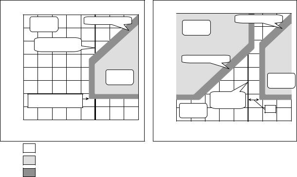
3Bypass ventilation prohibited
When the conditions described below are applicable, the ventilation mode will be fixed at Lossnay ventilation. When bypass ventilation has been set from the remote controller or the system controller, damper operation will be set to Lossnay ventilation, even though bypass ventilation is displayed on the ventilation mode display.
●When the outdoor temperature is 8ºC or lower. (Product condensation prevention)
When bypass ventilation prohibition has been set under this condition, the prohibition will be cancelled when the outdoor temperature goes from a temperature of less than 10 ºC to one higher than 10ºC.
●When there is an outdoor temperature (Outdoor Air) thermistor fault.
●When, in the automatic ventilation mode, there is an outdoor temperature (Outdoor Air) or indoor temperature (Return Air) thermistor fault.
●When Lossnay is set to the automatic ventilation mode and interlocked with Mr.Slim or City Multi indoor units
set to the fan operation mode.
4Damper operation
The damper provides control with a 30 second period. Accordingly, a delay of 30 seconds maximum may be generated from ventilation mode switching to damper operation.
5Automatic ventilation algorithm temperature map
Ventilation mode switching of Lossnay ventilation/Bypass ventilation in the automatic ventilation mode is in accordance with the following map.
a.Systems interlocked with Mr. Slim and City Multi indoor units
The map will differ depending on the operation mode that has been set with the A-control remote controller or the K-control remote controller for Mr. Slim, or the MA remote controller or the ME remote controller for City Multi indoor units. There will be switching to the ventilation mode in conjunction with the set temperature of the air conditioner remote controller. Note that the “b” map will be followed while Mr. Slim and City Multi indoor units are stopped.
Cooling mode (Winter)
|
40 |
|
|
|
|
|
|
|
|
|
|
Lossnay |
|
|
Undetermined area |
|
|||
|
35 |
Ventilation |
|
|
|
|
|
|
|
ºC |
30 |
Remote controller |
|
|
|
|
|||
temperature |
|
Set temperature |
|
|
|
|
|
||
25 |
|
|
|
|
|
|
|
|
|
20 |
|
|
|
|
|
|
|
|
|
|
|
|
|
|
|
Bypass |
|
||
Outdoor |
|
|
|
|
|
|
|
||
15 |
|
|
|
|
|
Ventilation |
|
||
10 |
Bypass ventilation |
|
|
|
|
|
|
||
|
|
|
|
|
|
|
|
||
|
5 |
Prohibition temperature 8ºC |
|
|
|
|
|||
|
|
|
|
|
|
|
|
|
|
|
0 |
|
|
|
|
|
|
|
|
|
0 |
5 |
10 |
15 |
20 |
25 |
30 |
35 |
40 |
Indoor temperature ºC
Heating mode (Summer)
|
40 |
|
|
|
Undetermined area |
|
|||
|
|
Bypass |
|
|
|||||
|
35 |
|
|
|
|
|
|
||
|
Ventilation |
|
|
|
|
|
|
||
|
|
|
|
|
|
|
|
||
ºC |
30 |
|
|
|
|
|
|
|
|
|
|
|
|
|
|
|
|
|
|
temperature |
25 |
Undetermined area |
|
|
|
|
|
||
|
|
|
|
|
|
||||
20 |
|
|
|
|
|
|
|
|
|
|
|
|
|
|
|
|
Bypass |
||
Outdoor |
15 |
|
|
|
|
|
|
||
|
|
|
|
|
|
Ventilation |
|||
|
|
|
|
|
|
|
|||
10 |
|
|
|
|
|
|
|
|
|
|
|
|
|
|
|
|
|
|
|
|
5 |
Lossnay |
Set temperature |
|
|
4ºC |
|
||
|
|
|
|
|
|
||||
|
|
Ventilation |
|
|
|
|
|
|
|
|
0 |
|
|
|
|
|
|
|
|
|
0 |
5 |
10 |
15 |
20 |
25 |
30 |
35 |
40 |
Indoor temperature ºC
Lossnay ventilation area
Bypass ventilation area
Undetermined area
When operation starts under this condition, Lossnay ventilation will be activated.
When this condition is reached after operation starts, the current ventilation mode is maintained.
— 29—
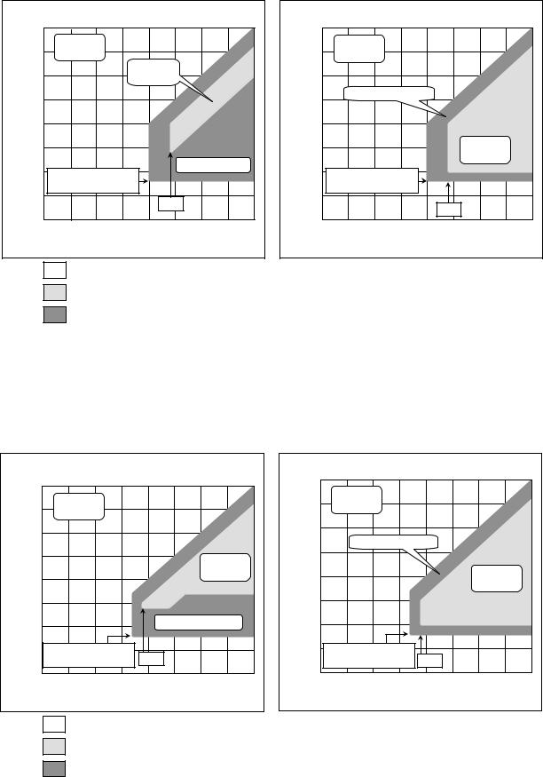
b.When there is no interlocking with Mr. Slim and City Multi indoor units Pattern 1. Normal ventilation mode
When PZ-60DR-E is used, operation will be at the setting of automatic ventilation adjustment pattern “1” of the remote controller function selection. When PZ-60DR-E is not used, operation will be at the OFF setting of function selection switch (SW2-7) on the Lossnay circuit board.
Outdoor temperature ºC
When an outdoor temperature of 28ºC has not |
|
|
When an outdoor temperature of 28ºC has been |
|
||||||||||||||
40 |
|
been detected within 24 hours |
|
|
|
40 |
|
detected within 24 hours |
|
|
||||||||
|
|
|
|
|
|
|
|
|
|
|
|
|
|
|
|
|
||
35 |
Lossnay |
|
|
|
|
|
|
|
35 |
Lossnay |
|
|
|
|
|
|
||
Ventilation |
|
|
|
|
|
|
|
Ventilation |
|
|
|
|
|
|
||||
30 |
|
|
|
Bypass |
|
|
|
ºC |
30 |
|
|
|
|
|
|
|
|
|
|
|
|
Ventilation |
|
|
|
|
|
|
|
|
|
|
|
||||
|
|
|
|
|
|
temperature |
|
|
|
|
|
|
|
|
||||
25 |
|
|
|
|
|
|
|
|
25 |
Undetermined area |
|
|
|
|
||||
|
|
|
|
|
|
|
|
|
|
|
|
|
||||||
|
|
|
|
|
|
|
|
|
|
|
|
|
|
|
|
|
||
20 |
|
|
|
|
|
|
|
|
|
20 |
|
|
|
|
|
|
|
|
15 |
|
|
|
|
|
|
|
|
Outdoor |
15 |
|
|
|
|
|
Bypass |
|
|
Bypass ventilation |
|
|
|
|
|
Bypass ventilation |
|
|
|
Ventilation |
|
|||||||
10 |
|
Undetermined area |
|
10 |
|
|
|
|
||||||||||
|
|
|
|
|
|
|
|
|
|
|
|
|
|
|||||
|
|
|
|
|
|
|
|
|
|
|
|
|
|
|
|
|||
5 |
Prohibition temperature 8ºC |
|
|
|
|
|
5 |
Prohibition temperature 8ºC |
|
|
|
|
|
|||||
|
|
|
|
24ºC |
|
|
|
|
|
|
|
|
|
|
|
|
||
|
|
|
|
|
|
|
|
|
|
|
|
|
|
24ºC |
|
|
|
|
0 |
|
|
|
|
|
|
|
|
|
0 |
|
|
|
|
|
|
|
|
|
|
|
|
|
|
|
|
|
|
|
|
|
|
|
|
|
||
0 |
5 |
10 |
15 |
20 |
25 |
30 |
35 |
40 |
|
0 |
5 |
10 |
15 |
20 |
25 |
30 |
35 |
40 |
|
|
|
Indoor temperature ºC |
|
|
|
|
|
|
Indoor temperature ºC |
|
|
||||||
Lossnay ventilation area
Bypass ventilation area
Undetermined area
When operation starts under this condition, Lossnay ventilation will be activated.
When this condition is reached after operation starts, the current ventilation mode is maintained.
Pattern 2. Outdoor cooling priority mode
When the outdoor temperature is lower than the indoor temperature, this mode actively takes in the outdoor air for cooling.
When PZ-60DR-E is used, operation will be at the setting of automatic ventilation adjustment pattern “2” of the remote controller function selection. When PZ-60DR-E is not used, operation will be at the ON setting of function selection switch (SW2-7) on the Lossnay circuit board.
When an outdoor temperature of 17ºC has not
|
|
|
been detected within 24 hours |
|
|
|
40 |
||||
|
40 |
|
|
|
|
|
|
|
|
|
|
|
|
|
|
|
|
|
|
|
|
|
|
|
35 |
|
Lossnay |
|
|
|
|
|
|
35 |
|
|
|
Ventilation |
|
|
|
|
|
|
|||
|
|
|
|
|
|
|
|
|
|||
ºC |
30 |
|
|
|
|
|
|
|
|
ºC |
30 |
|
|
|
|
|
|
|
|
|
|||
|
|
|
|
|
|
|
|
|
|
||
temperature |
25 |
|
|
|
|
|
|
|
Bypass |
temperature |
25 |
|
|
|
|
|
|
|
|
||||
|
|
|
|
|
|
|
|
|
|||
20 |
|
|
|
|
|
|
Ventilation |
20 |
|||
|
|
|
|
|
|
|
|
||||
|
|
|
|
|
|
|
|
|
|||
15 |
|
|
|
|
|
|
|
|
15 |
||
Outdoor |
|
|
|
|
|
|
|
|
Outdoor |
||
|
|
|
|
|
|
|
|
|
|||
10 |
|
|
|
|
|
Undetermined area |
10 |
||||
|
|
|
|
|
|
|
|
|
|
||
|
5 |
Bypass ventilation |
|
19ºC |
|
|
|
5 |
|||
|
|
Prohibition temperature 8ºC |
|
|
|
|
|||||
|
0 |
|
|
|
|
|
|
|
|
|
0 |
|
|
0 |
5 |
10 |
15 |
20 |
25 |
30 |
35 |
40 |
|
Indoor temperature ºC
When an outdoor temperature of 17ºC has been detected within 24 hours
|
Lossnay |
|
|
|
|
|
|
|
|
Ventilation |
|
|
|
|
|
|
|
|
|
Undetermined area |
|
|
|
|
||
|
|
|
|
|
|
Bypass |
|
|
|
|
|
|
|
|
Ventilation |
|
|
|
Bypass ventilation |
|
|
|
|
|
|
|
|
Prohibition temperature 8ºC |
19ºC |
|
|
|
|
||
0 |
5 |
10 |
15 |
20 |
25 |
30 |
35 |
40 |
Indoor temperature ºC
Lossnay ventilation area
Bypass ventilation area
Undetermined area
When operation starts under this condition, Lossnay ventilation will be activated.
When this condition is reached after operation starts, the current ventilation mode is maintained.
— 30—
Loading...