


LANCER
Evolution - IX
•Chassis
•Engine
•Wiring Diagrams
•Technical Information
SERVICE MANUAL
Supplement

LANCER
EVOLUTION IX
FOREWORD
This manual contains details of the main changes to the 2005 model Lancer Evolution IX. Only differences to the current Lancer Evolution VIII MR are included, so please use this manual in conjunction with the related manuals as listed on the following page.
Please read this manual carefully so that servicing can be done correctly and quickly, and vehicle performance maintained.
This manual is based on the current (March 2005) model. Please bear in mind that vehicle specifications may change and that future models may not be the same.
Please note that all the units shown in this manual follow the internationally recognized SI unit system, and that the used previously are not shown alongside the SI units. (Nevertheless, please take care because units in reference documents may be shown in the units which were previously used).
Any opinions, requests or questions concerning this manual, should be written on the ‘Servicing Comments Form’ at the end of the manual, and sent to us by fax.
March 2005
MITSUBISHI MOTOR CORPORATION
CONTENTS |
|
General ........................................................ |
00 |
Engine ......................................................... |
11 |
Fuel .............................................................. |
13 |
Engine Cooling ........................................... |
14 |
Intake and Exhaust .................................... |
15 |
Engine Electrical ........................................ |
16 |
Rear axle ..................................................... |
27 |
Wheels and tyres........................................ |
31 |
|
33 |
Front suspension ....................................... |
........Body |
|
42 |
Body....................................................................... |
|
Exterior ........................................................ |
51 |
Interior and SRS Airbag............................. |
N 52 |
Chassis Electrical......................................... |
|
|
54 |
This manual is printed on recycled paper
Related materials
Title |
No. |
Issue |
Title |
No. |
Issue |
|
|
date |
|
|
date |
New model manuals |
|
|
Body edition service manual |
|
|
• Lancer Sedia |
1036K30 |
2000/5 |
• Lancer Sedia |
1036K50 |
2000/5 |
• Lancer Sedia |
1036K31 |
2000/7 |
• Lancer Sedia (supplement) |
1036K51 |
2000/7 |
• Lancer Evolution VII |
1036K32 |
2001/1 |
• Lancer Evolution VII |
1036K52 |
2001/5 |
• Lancer Sedia |
1036K33 |
2001/5 |
(supplement) |
|
|
• Lancer Sedia |
1036K34 |
2001/5 |
• Lancer Sedia (supplement) |
1036K53 |
2001/10 |
• Lancer Evolution VII |
1036K35 |
2002/1 |
• Lancer Evolution VII_MR |
1036K54 |
2004/2 |
• Lancer Sedia |
1036K36 |
2002/5 |
(supplement) |
|
|
• Lancer Evolution VII |
1036K37 |
2003/1 |
|
|
|
• Lancer |
1036K38 |
2003/2 |
|
|
|
• Lancer |
1036K39 |
2003/12 |
Electrical wiring service manual |
|
|
• Lancer Evolution VII_MR |
1036K40 |
2004/2 |
• Lancer Evolution IX |
1036K82 |
2005/3 |
• Lancer* |
1036K41 |
2004/3 |
|
|
|
• Lancer |
1036K42 |
2005/1 |
|
|
|
• Lancer Evolution IX |
1036K43 |
2005/3 |
|
|
|
Service manuals |
|
|
Engine service manual |
|
|
• Lancer Sedia |
1036K00 |
2000/5 |
• 4G6 engine |
1039G46 |
2001/1 |
• Lancer Sedia |
|
|
|
|
|
(supplement) |
1036K01 |
2000/7 |
• 4G6 engine (supplement) |
1039G63 |
2003/1 |
• Lancer Evolution VII |
1036K02 |
2001/1 |
• 4G6 engine (supplement) |
1039G71 |
2003/3 |
(supplement) |
|
|
|
|
|
• Lancer Sedia |
|
|
|
|
|
(supplement) |
1036K03 |
2001/5 |
|
|
|
• Lancer Sedia |
|
|
|
|
|
(supplement) |
1036K04 |
2001/10 |
|
|
|
• Lancer Evolution VII |
1036K05 |
2002/1 |
Transmission service manuals |
|
|
(supplement) |
|
|
• W5M51 manual transmission |
1039M17 |
2001/1 |
• Lancer Sedia |
|
|
|
|
|
(supplement) |
1036K06 |
2002/5 |
• W5M51 manual transmission |
1039M22 |
2003/1 |
• Lancer Evolution VII |
1036K07 |
2003/1 |
(supplement) |
|
|
(supplement) |
|
|
• WGMAA manual transmission |
1039M23 |
2003/1 |
• Lancer Sedia |
|
|
|
|
|
(supplement) |
1036K08 |
2003/2 |
|
|
|
• Lancer Sedia |
|
|
|
|
|
(supplement) |
1036K09 |
2003/12 |
|
|
|
• Lancer Evolution VII MR |
1036K10 |
2004/2 |
|
|
|
• Lancer* |
1036K41 |
2004/3 |
|
|
|
• Lancer |
1036K11 |
2005/1 |
|
|
|
*Indicates where the new model manual was published with the service manual in a single volume.
WARNING REGARDING THE SERVICING OF VEHICLES FITTED WITH SRS AIR BAGS AND SEATBELTS WITH PRETENSIONERS
Warning
1.Improper servicing or maintenance of any SRS air bag or pre-tensioner fitted seatbelt component, or related parts, could cause serious injury through the SRS air bag or pre-tensioner fitted seatbelt being activated unintentionally or accidentally.
2.The SRS-ECU, the driver’s side air bag module, the passenger side air bag module, the pre-tensioner fitted seatbelts and the clock spring, should be removed if there is a chance of them being affected by heat during painting work.
•93ºC and above: the SRS-ECU, the driver’s air bag module, the passenger’s air bag module and the clock spring should be removed.
•90ºC and above: the pre-tensioner fitted seatbelts should be removed.
3.Servicing and maintenance of any SRS air bag or pre-tensioner fitted seatbelt components, or related parts, must be performed by an authorized Mitsubishi dealer.
4.Servicing and maintenance of any SRS air bag or pre-tensioner fitted seatbelt components, or related parts, must only be undertaken after this service manual (specifically Section 52B-SRS air bags) has been carefully studied.

GENERAL –TROUBLESHOOTING FOR INSPECTIONS, MODEL LINE-UP, |
00-1 |
|
|
RELEVANT VEHICLE NUMBERS |
|
|
|
|
|
SECTION 00 |
|
|
GENERAL |
|
|
CONTENTS |
|
Inspection guidelines and |
Relevant vehicle numbers |
........................1 |
troubleshooting.......................................... |
1 |
|
Model line-up.............................................. |
1 |
|
|
|
|
Inspection guidelines and troubleshooting
With the introduction of new settings for the MB992006 (Extra Fine Probe) special tool, the guidelines for inspecting the connector have been changed. Other servicing guidelines remain unchanged.
Making an inspection with the connector attached (so the electrical circuit is complete) <non-waterproof connector>
The test bar should be inserted from the harness side. If the control unit or the connector is too small, and the test bar cannot be inserted, do not attempt to force it in. Instead, use the MB992006 (Extra Fine Probe) special tool.
Model line-up
Note
● Indicates a new model, indicates a special model, X indicates a discontinued model.
Relevant vehicle numbers
GH-CT9A: CT9A-0400001 ~

ENGINE – GENERAL, SERVICING STANDARDS, SEALANTS |
11-1 |
|
|
|
|
SECTION 11
ENGINE
CONTENTS
General ....................................................... |
1 |
|
Servicing standards ................................. |
1 |
|
Sealants ..................................................... |
1 |
|
Special tools .............................................. |
2 |
|
Engine tuning ............................................. |
4 |
|
1. |
Checking of revolutions when idling ................ |
4 |
2. |
Checking compression pressure....................... |
4 |
Camshaft, valve stem seals |
.....................4 |
Cylinder head gaskets............................. |
14 |
Timing belt, timing belt B........................ |
20 |
Engine ASSY ............................................ |
28 |
General
The following servicing guidelines have been prepared for vehicles which use the 4G63-MIVEC-T/C engine. Other servicing guidelines remain unchanged.
Servicing standards
Sealants |
Note
The code inside the brackets ( ) is the actual product number.

11-2 |
|
ENGINE – SPECIAL TOOLS |
||
Special tools |
|
|
|
|
|
|
|
|
|
Tool |
Number |
Name |
Function |
|
|
|
|
|
|
|
|
MB991502 |
MUT-II Sub |
Checking and adjusting the tension in |
|
|
|
ASSY |
timing belt B |
|
|
|
|
Note |
|
|
|
|
If a MUT-III main harness A is |
|
|
|
|
connected to a vehicle not fitted with |
|
|
|
|
CAN, there is a chance that a pulse |
|
|
|
|
signal will be entered in the simulated |
|
|
|
|
vehicle speed line, when the MUT-III is |
|
|
MB991955 |
MUT-III Sub ASSY |
activated. Therefore, use a MUT-III main |
|
|
A: MB991824 |
A: Vehicle |
harness B with vehicles not fitted with |
|
|
B: MB991827 |
Communication |
CAN. |
|
|
C: MB991910 |
Interface (VCI) |
|
|
|
D: MB991911 |
B: USB cable |
|
|
|
E: MB991825 |
C: MUT-III Main |
|
|
|
F: MB991826 |
harness A |
|
|
|
|
(For vehicles |
|
|
|
|
fitted with CAN) |
|
|
|
|
D: MUT-III Main |
|
|
|
|
harness B |
|
|
|
|
(For vehicles |
|
|
|
|
not fitted with |
|
|
|
|
CAN) |
|
|
|
|
E: Adaptor |
|
|
|
|
F: Trigger harness |
|
|
DO NOT USE |
|
|
|
|
|
|
|
|
MB991668 |
Belt tension meter |
• Checking the tension in the drive belt. |
A: MB991969 |
set |
(Use in conjunction with VCI) |
B: MB991670 |
A: Tension meter |
• Checking the tension in the balancer |
|
cartridge |
timing belt. |
|
B: Mic ASSY |
Adjusting (Use in conjunction with VCI) |
|
|
|
MD998772 |
Valve spring |
Compression of the valve spring. |
|
compressor |
|

|
ENGINE – SPECIAL TOOLS |
11-3 |
||
|
|
|
|
|
Tool |
Number |
Name |
Function |
|
|
MD998737 |
Valve stem seal |
Valve stem seal installation |
|
|
|
installer |
|
|
|
|
|
|
|
|
MD998713 |
Camshaft oil seal |
Camshaft oil seal installation |
|
|
|
installer |
|
|
|
|
|
|
|
|
MB991654 |
Cylinder head bolt |
Cylinder head bolt removal, installation |
|
|
|
wrench |
|
|
|
|
|
|
|
|
MB991367 |
Special spanner |
Holding the crankshaft sprocket |
|
|
|
|
|
|
|
MB991385 |
Pins |
|
|
|
|
|
|
|
|
MB991704 |
Battery harness |
Checking and adjustment of the tension in the |
|
|
|
|
balancer timing belt (Use in conjunction with VCI |
|
|
|
|
or MUT-II) |
|
|
|
|
|
|
|
MD998738 |
Adjusting bolt |
Holding the tensioner arm or the auto-tensioner |
|
|
|
|
adjuster |
|
|
|
|
|
|
|
MD998767 |
Tensioner pulley |
Adjusting the tension of the timing belt |
|
|
|
socket wrench |
|
|
|
|
|
|
|

11-4 |
ENGINE – SPECIAL TOOLS, ENGINE TUNING, CAMSHAFT, VALVE STEM SEAL |
|||||
|
|
|
|
|
|
|
Tool |
|
|
|
Number |
Name |
Function |
|
|
|
|
|
|
|
|
|
|
|
MB991454 |
Engine hanger |
Holding the engine assembly while the |
|
|
|
|
|
balancer |
transmission assembly is removed/installed |
|
|
|
|
|
|
|
|
|
|
|
Recommended |
Mechanical engine |
|
|
|
|
|
tools MZ203830 |
hanger |
|
|
|
|
|
panzai or |
|
|
|
|
|
|
MZ203831 safe |
|
|
|
|
|
|
vehicle handling |
|
|
|
|
|
|
|
|
|
|
|
|
|
MB991928 |
Engine hanger |
|
|
|
Slide bracket (HI) |
|
|
||
|
|
|
A: MB991929 |
A: joint (50) x2 |
|
|
|
|
|
|
|
||
|
|
|
|
B: MB991930 |
B: joint (90) x2 |
|
|
|
|
|
C: MB991931 |
C: joint (140) x2 |
|
|
|
|
|
D: MB991932 |
D: Foot (standard) x4 |
|
|
|
|
|
E: MB991933 |
E: Foot (short) x4 |
|
|
|
|
|
F: MB991934 |
F: Chain and hook |
|
|
|
|
|
|
ASSY |
|
|
|
|
|
|
|
|
Engine tuning
1. Checking revolutions when the engine is idling
The standard revolutions for when the engine is idling have been changed. Other servicing guidelines remain unchanged.
Standard revolutions: 800 ± 50 r/min
2. Checking compression pressure
The standard for compression pressure and the limit for compression pressure have been changed. Other servicing
guidelines remain unchanged.
Standard compression pressure: 1000 kPa – 250 r/min Compression pressure limit: 650 kPa – 250r/min
Camshaft, valve stem seal
Removal and fitting
Caution
1.If Brembo brake callipers are being used take care that they are not scratched by other components or tools because there is a chance that the paint might peel off. In addition, if any brake fluid gets on the callipers, it should be wiped off immediately.
2.Parts marked with * should be removed and then fitted for each cylinder in turn.
Jobs to be completed before removal and after fitting
•Removal and refitting of the undercover (Ref Section 51: Front bumper)
•Checking the tension of the drive belt (only after fitting)
•Draining and refilling of the coolant
•Removal and refitting of the air duct
•Removal and refitting of air pipe C
•Removal and refitting of the timing belt (refer to P11-20)

ENGINE – CAMSHAFT, VALVE STEM SEAL |
11-5 |
Removal procedure |
|
|
|
1. |
Oil feeder control valve connector |
8. |
Connection of the control harness |
O 2. |
Oil feeder control valve |
9. |
Vacuum hose |
O 3. |
O-ring |
10. PCV hose |
|
4. |
Breather hose |
A N 11. |
Connection of the radiator upper hose |
• Secondary air control valve |
12. Camshaft position sensor connector |
||
|
(refer to Section 15-2: Secondary Air |
|
(exhaust side) |
|
Control System) |
13. Camshaft position sensor connector |
|
5. |
Centre cover |
|
(inlet side) |
• |
Ignition coil |
14. Connection of the earth cable |
|
6. |
O2 sensor connector |
M 15. Rocker cover ASSY |
|
7. |
Crank angle sensor connector |
16. Spark plug hole gasket |
|
|
|
||
17. Rocker cover gasket
11-6 |
ENGINE – CAMSHAFT, VALVE STEM SEAL |
During assembly, apply engine oil to all sliding parts.
18.Camshaft position sensor support cover
19.Camshaft position sensor support cover gasket
L 20. Camshaft position sensing cylinder (exhaust side)
J 21. Camshaft position sensor support
22.Camshaft position sensor support cover
23.Camshaft position sensor support cover gasket
K 24. Camshaft position sensing cylinder (inlet side)
J 25. Camshaft position sensor supportB I 26. Camshaft sprocket (exhaust side)
G 27. Camshaft oil seal
F 28. Camshaft bearing cap front
F 29. Camshaft bearing cap rear left
F 30. Camshaft bearing cap No. 2
F 31. Camshaft bearing cap No. 5
F 32. Camshaft bearing cap No. 3
F 33. Camshaft bearing cap No. 4
E 34. Exhaust camshaft
35.Camshaft sprocket cap
36.Washer
B H 37. Camshaft sprocket (inlet side)G 38. Camshaft oil seal
F 39. Camshaft bearing cap front
F 40. Camshaft bearing cap rear right
F 41. Camshaft bearing cap No. 2
F 42. Camshaft bearing cap No. 5
F 43. Camshaft bearing cap No. 3
F 44. Camshaft bearing cap No. 4
E 45. Inlet camshaft
ENGINE – CAMSHAFT, VALVE STEM SEAL |
11-7 |
|
|
|
|
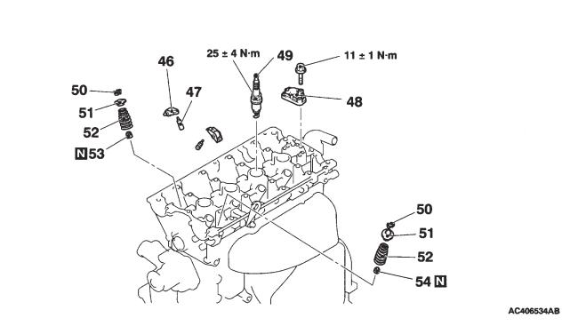
|
D |
46. Rocker arm |
|
51. Valve spring retainer |
|
47. Rush adjuster |
B 52. Valve spring |
|||
|
48. Oil delivery body |
A |
53. Inlet valve stem seal |
|
C C |
49. Spark plug |
A |
54. Exhaust valve stem seal |
|
50. Valve spring retainer lock |
|
|
|
|

11A-8 |
ENGINE – CAMSHAFT, VALVE STEM SEAL |
Locations for the application of lubricant and seals
<View from A>
Semi-dry sealant: Three bond 1207F
Semi-dry sealant:
Three bond 1207D
(around the lip):
Engine oil
Semi-dry sealant: Three bond 1207F
<Viewed looking down onto the cylinder head>
Semi-dry sealant: Three bond 1207D
ENGINE – CAMSHAFT, VALVE STEM SEAL |
11-9 |
Indicator marks
Colour of main |
|
Colour of main |
body: grey |
|
body: grey/green |
|
|
|
Inlet side |
|
Exhaust side |
|
|
|
Valve
Valve stem seal
Removal guidelines
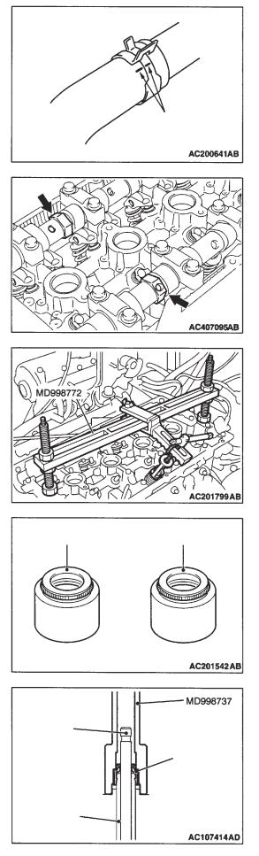
A Detaching the radiator upper hose
Align the indicator marks on the radiator upper hose and the hose clamp, and then detach the radiator upper hose.
B Removing the camshaft sprockets
Grip the hexagonal part of the camshaft with a wrench, loosen the mounting bolt, and remove the camshaft sprocket.
C Removing the valve spring retainer lock
Compress the valve spring using the special tool for compressing valve springs (MD998772), and remove the valve spring retainer lock.
Caution
When removing the valve spring retainer lock, each cylinder piston should be in the top dead centre position. If pistons are not in the top dead centre position, valves could fall into the cylinders.
Fitting guidelines
A Fitting the exhaust valve stem seals and the inlet valve stem seals
1.Inlet valve stem seals and exhaust valve stem seals can be distinguished by checking the colour of the rubber parts.
2.Apply a small quantity of engine oil to the valve stem seals.
3.Place the valve stem component into the guides, and then insert a new valve stem seal into the valve stem guide by using the special tool for installing valve stem seals.
Caution
(1)Valve stem seals cannot be re-used.
(2)Please use the special tool for installing valve stem seals (MD998737) because oil could leak if the valve stem seals are not fitted correctly.
Valve guide

11-10 ENGINE – CAMSHAFT, VALVE STEM SEAL
|
B Fitting the valve spring |
|
Rocker arm side |
||
Fit the valve spring so that the end of the valve spring which has |
||
|
||
|
the smaller radius is on the rocker arm side. |
C Fitting the valve spring retainer lock
In the same way as when the valve spring retainer lock was removed, compress the valve spring using the special tool for compressing valve springs (MD998772), and fit the valve spring retainer lock.
D Fitting the rush adjuster
Caution
If a rush adjuster is being reused, it must be washed and inspected before fitting.
(Ref: Engine Service Manual)
|
|
|
|
|
|
|
E Fitting the camshaft |
|
|
|
|
|
|
|
|
||
|
|
|
|
Front of engine |
||||
|
|
|
|
1. |
Remove any sealant from the cylinder head. |
|||
<inlet side> |
|
|
|
|
|
|
||
|
|
|
|
|
|
2. |
Apply engine oil to the camshaft cams and journals. |
|
|
|
|
|
|
|
|
||
|
|
|
|
|
|
|
||
|
|
|
|
|
|
|
3. |
Fit the camshaft to the cylinder head. |
|
|
|
slit |
|
|
|
||
|
|
|
|
|
|
|
|
|
|
Caution |
|
Ensure that the inlet and exhaust sides are not the wrong way |
<exhaust side> |
round. |
|
|
|
slit |
F Fitting the camshaft bearing cap No.4, the camshaft
Approx. 4° bearing cap No.3, the camshaft bearing cap No.5, the dowel pins
camshaft bearing cap No.2, the rear camshaft bearing cap, and the front camshaft bearing cap
1.Set the camshaft dowel pins in the position shown in the diagram.
inlet side |
|
exhaust side |
|
|
|

ENGINE – CAMSHAFT, VALVE STEM SEAL |
11-11 |
bearing cap No.
Front of engine
mark indicating inlet side or exhaust side
Front of engine
<Inlet side>
front mark
Front of engine
<Exhaust side>
front mark
Front of engine
camshaft oil seal
2.Because camshaft bearing caps Nos. 2~5 are the same shape, check the identification marks on them so that the bearing cap number and the inlet and exhaust sides are not mistaken. Then fit them in the direction shown in the diagram.
Identification marks (stamped on the front bearing cap, and on bearing cap Nos. 2~5).
I: inlet side
E: exhaust side
3.Apply sealant at the 8 places shown in the diagram of the top view of the cylinder head.
Semi-dry sealant: Three bond 1207D
4.Fit the rear camshaft bearing cap in the direction indicated by the front mark.
5.In just the same way as for bearing caps Nos. 2~5, check the identification marks on the front camshaft bearing cap so that the exhaust side and the inlet side are not mistaken.
6.Tighten the bearing cap mounting bolts gradually, 2~3 turns at a time, to the specified torque.
Tightening torque: 20 ± 1 N•m
7.Check that the rocker arm has been fitted correctly.
Note
Completely wipe away any sealant that has been squeezed out.
G Fitting the camshaft oil seal
1.Apply engine oil around the entire circumference of the oil seal lip.
2.Insert the oil seal using the special tool for installing the camshaft oil seal (MD998713), as shown in the diagram.
(engine oil)

11-12 |
|
|
|
ENGINE – CAMSHAFT, VALVE STEM SEAL |
||||||
|
|
|
|
|
|
|
|
|
H Fitting the camshaft sprocket (inlet side) |
|
|
|
|
|
|
1. |
Apply engine oil to the edges of the camshaft, and to the parts |
||||
|
|
|
|
|
|
|
|
|
|
of the camshaft sprocket which will make contact with the |
|
|
Front of |
|
|
|
|
|
|||
|
|
|
|
|
(engine oil) |
|
||||
|
|
engine |
|
|
|
|
camshaft. |
|||
|
|
|
|
|
|
|
||||
|
|
|
|
|
|
|
||||
|
|
|
|
|
2. |
Match up the camshaft dowel pins with the dowel pin holes in |
||||
|
|
|
|
|
||||||
|
|
|
|
|
|
|
|
|
|
the camshaft sprocket, and fit the camshaft into the camshaft |
|
|
|
|
|
|
|
|
|
|
sprocket. |
|
|
|
|
|
3. |
Hold the hexagonal part of the camshaft with a wrench, and |
||||
|
|
|
|
|
|
|
|
|
|
check that the camshaft sprocket cannot be twisted. |
|
|
|
|
|
|
|
|
|
|
Note |
|
camshaft |
|
|
|
|
|
||||
|
sprocket |
|
|
|
|
|
|
|
This operation is necessary because it is impossible to check by |
|
|
|
|
|
|
|
|
|
|
|
looking whether the camshaft dowel pins are inserted into the |
|
|
|
|
|
|
|
|
|
|
|
|
|
|
|
|
|
|
|
|
|
dowel pin holes in the camshaft sprocket. |
|
|
|
|
|
4. |
Apply engine oil to the screw thread and the underside of the |
||||
|
|
|
|
|
|
|
|
|
|
camshaft sprocket mounting bolt, and in the same way as when |
|
|
|
|
|
|
|
|
|
the camshaft sprocket was removed, hold the camshaft in place |
|
|
|
Front of |
|
|
|
|
|
|||
|
|
engine |
|
|
(engine oil) |
|
using a wrench and tighten the bolt to the specified torque. |
|||
|
|
|
|
|
|
|
|
|
|
|
Tightening torque: 65 ± 5 N•m
camshaft sprocket
I Fitting the camshaft sprocket (exhaust side)
In the same way as when the camshaft sprocket was removed, hold the hexagonal part of the camshaft with a wrench and tighten the bolt to the specified torque.
Tightening torque: 89 ± 9 N•m
<Exhaust side>
<Inlet side>
J Fitting the camshaft position sensor support
1.Remove any sealant from the camshaft position sensor support.
2.As shown in the diagram, apply sealant to the flange of the camshaft position sensor support, and then fit it to the cylinder head.
Semi-dry sealant: Three bond 1207F
3.Tighten the mounting bolts for the camshaft position sensor support to the specified torque.
Tightening torque: 14 ± 1 N•m

ENGINE – CAMSHAFT, VALVE STEM SEAL |
11-13 |
<Intake side>
dowel pin
pane
approx. 45º |
dowel pin |
pane (small)
pane (large)
K Fitting the camshaft position sensing cylinder (inlet side)
1.Set the inlet camshaft dowel pin in the position shown in the diagram (No.1 cylinder compression top dead centre).
2.Tighten the mounting bolts for the camshaft position sensing cylinder to the specified torque.
Tightening torque: 22 ± 4 N•m
L Fitting the camshaft position sensing cylinder (exhaust side)
1.Set the exhaust camshaft dowel pin in the position shown in the diagram (No.1 cylinder compression top dead centre).
Note
Under pressure from the exhaust valve spring, it will turn slightly in an anti-clockwise direction.
2.As shown in the diagram, fit the pane (small) of the camshaft position sensing cylinder (exhaust side) so that it is in a position approximately 45° to the exhaust camshaft dowel pin.
3.Tighten the mounting bolts for the camshaft position sensing cylinder to the specified torque.
Tightening torque: 22 ± 4 N•m
Front of engine
Protrusion
M Fitting the locker cover assembly
1.Apply sealant to the 8 places on the rocker cover gasket as shown in the diagram.
Semi-dry sealant: Three bond 1207D
2.Fit the rocker cover assembly onto the cylinder head.
N Connecting the radiator upper hose
1.Insert the radiator upper hose as far as the protrusion on the water outlet fitting.
2.Match up the indicator marks on the radiator upper hose and the hose clamp, in order to fit the radiator upper hose.
water outlet |
|
indicator marks |
fitting |
|
|
|
|
|
|
|
|

11-14 ENGINE – CAMSHAFT, VALVE STEM SEAL, CYLINDER HEAD GASKET
O Fitting the O-ring/oil feeder control valve
Caution
1. Do not re-use O-rings.
Tape
2. When fitting O-rings, first wind some non-adhesive tape (seal tape etc) around the oil channel of the oil feeder control valve, in order to prevent damage to the O-ring. If the O-ring touches the oil it could start an oil leak.
1.Apply engine oil to the O-ring on the oil feeder control valve.
2.Fit the oil feeder control valve to the cylinder head.
3.Tighten the mounting bolts for the oil feeder control valve to the specified torque.
Tightening torque: 11 ± 1 N•m
Cylinder head gasket
Removal and fitting
Jobs to be completed before removal and after fitting
•Measures to prevent fuel leaking. <Only before removal>
•Check for fuel dripping. <Only after fitting>
•Removal and refitting of the strut tower bar.
•Removal and refitting of the valence. (Ref Section 51: Front bumper)
•Check the tension of the drive belt. <Only after fitting>
•Adjustment of the axle letter cable. <Only after fitting>
•Draining and replacing the engine oil.
•Draining and replacing the coolant.
•Removal and refitting of the air cleaner.
•Removal and refitting of air pipe C.
•Removal and refitting of the battery and the battery tray.
•Removal and refitting of the centre cover. (Ref P11-5)
•Removal and refitting of the axle letter cable.
•Removal and refitting of the radiator.
•Removal and refitting of the front exhaust pipe.
•Removal and refitting of the timing belt. (Ref P11-20)
ENGINE – CYLINDER HEAD GASKET |
11-15 |
(engine oil)
Removal procedure
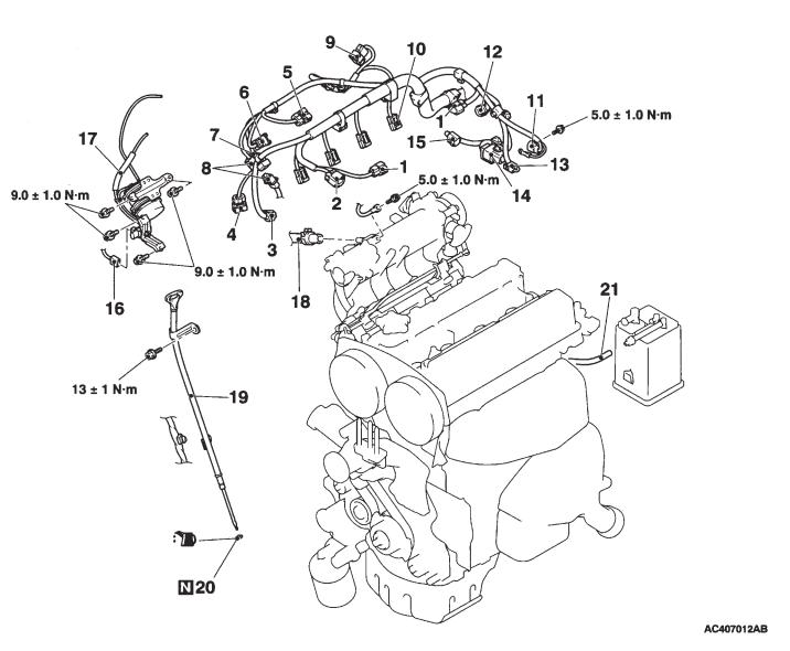
1.Ignition coil connector
2.O2 sensor connector
3.Oil feeder control valve connector
4.Crank angle sensor connector
5.Manifold absolute pressure sensor connector
6.Fuel pressure solenoid valve connector
7.Knock sensor connector
8.Purge control solenoid valve connector
9.Throttle position sensor connector
10.Injector connector
11.Exhaust camshaft position sensor connector
12.Inlet camshaft position sensor connector
13.Water temperature gauge unit connector
14.Joint control harness and transmission harness
15.Water temperature sensor connector
16.Secondary air control solenoid valve connector
17.Vacuum tank, solenoid valve, vacuum pipe and hose assembly
18.Brake booster vacuum hose connection
19.Oil level gauge and guide assembly
20.O-ring
21.Purge hose connection

11-16 |
ENGINE – CYLINDER HEAD GASKET |
(engine oil)
(when
cool)
(engine oil)
22. |
Alternator bracket connection |
D |
35. |
Oil return pipe gasket |
23. |
Inlet manifold stay |
|
36. |
Exhaust fitting bracket |
E 24. Eye bolt |
|
• Water outlet fitting and thermostat case |
||
25. |
Gasket |
|
|
assembly (Refer to Section 14: Water hose |
26. |
Eye bolt |
|
|
pipe) |
27. |
Gasket |
|
37. |
Water hose connection |
28. |
Oil feeder control valve pipe |
|
38. |
Heater hose connection |
29. |
Filter |
C |
39. |
Fuel return hose connection |
30. |
Oil pipe joint |
40. |
Fuel high pressure hose connection |
|
31. |
Gasket |
C |
41. |
O-ring |
32. |
Oil return pipe gasket |
A B |
42. |
Cylinder head bolt |
33. |
Oil return pipe |
|
43. |
Cylinder head assembly |
34. |
Oil return pipe gasket |
A |
44. |
Cylinder head gasket |

ENGINE – CYLINDER HEAD GASKET |
11-17 |
Removal guidelines
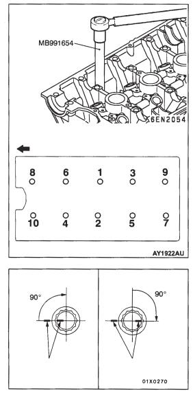
A Removing the cylinder head bolts
Use the special wrench for cylinder head bolts (MB991654) to turn the bolts 2~3 times in order to loosen them, before removing them in the numerical order as shown in the diagram.
Front of engine
Fitting guidelines
A Fitting the cylinder head gasket
1.Remove the gaskets which have been stuck onto the surface of the gasket.
Caution
Do not allow any foreign matter to get into the channels for coolant or oil, or into the cylinder.
2.Fit the cylinder head gasket to the cylinder head, so that the holes in the cylinder head gasket match up with the holes in the cylinder head.
B Fitting the cylinder head bolts
1. |
Check that the length of the body of cylinder head bolts is less |
|
|
|
than the maximum permitted. If the length is in excess of the |
|
|
maximum permitted, replace the bolt with a brand new one. |
(engine oil) |
||
|
|
Maximum length (A): 99.4mm |
|
|
|
2. |
Apply a small amount of engine oil to the screw thread of the |
|
|
|
bolt, and to the washer. |
11-18 |
ENGINE – CYLINDER HEAD GASKET |
Front of engine
Procedure number (4) |
|
Procedure number (5) |
paint mark |
|
paint mark |
|
|
|
3.Use the special wrench for cylinder head bolts (MB991654) to (loosely) tighten the bolts in the following order.
(1)In the order shown in the diagram, tighten the bolts to 78 ± 2 N•m.
(2)In reverse order to that shown in the diagram, completely loosen the bolts.
(3)In the order shown in the diagram, tighten the bolts to 20 ± 2 N•m.
(4)Make a paint mark on the top of the cylinder head bolt, and on the cylinder head, and tighten them to 90° as shown in the diagram.
(5)Tighten the bolts to 90° as shown in the diagram, and check that the paint mark on the top of the cylinder head bolt and the paint
mark on the cylinder head are in line.
Caution
1)If a bolt is tightened to an angle of less than 90° it has not been tightened sufficiently.
2)If the angle of tightening exceeds the regulation level, remove the bolt and start again from procedure number (1).
C Fitting the O-ring/fuel high pressure hose
1.Apply a little fresh engine oil to the O-ring.
Caution
Ensure that engine oil does not get inside the delivery pipe.
2.Without damaging the O-ring, twist the fuel high pressure hose to fit it to the delivery pipe, making sure that it is twisted smoothly.
3.If the hose cannot be twisted smoothly, there is a possibility that it may be biting into the O-ring, so remove the fuel high pressure hose, and check for any damage to the O-ring. If the O-ring is undamaged, reinsert it into the delivery pipe and check once more whether the hose can be turned smoothly.
4.Tighten the mounting bolts for the fuel high pressure hose to the specified torque.
Tightening torque: 5.0 ± 1.0 N•m.
ENGINE – CYLINDER HEAD GASKET |
11-19 |
D Fitting the oil return pipe gasket
Replace the gasket with a new one, and fit it to the protruded part shown in the diagram.
Note:
For the oil return pipe gasket on the turbocharger side, there is no direction for slotting it in.
Protrusion
E Fitting the eyebolts
Caution
When tightening the eyebolts, hold the oil pipe joint in place with a spanner so that it does not turn round as the eyebolts are tightened.
11-20 |
ENGINE – TIMING BELT, TIMING BELT B |
TIMING BELT, TIMING BELT B
Removal and fitting
Caution
If Brembo brake callipers are being used take care that they are not scratched by other components or tools because there is a chance that the paint might peel off. In addition, if any brake fluid gets on the callipers, it should be wiped off immediately.
Jobs to be completed before removal and after fitting
•Removal and refitting of the valence. (Ref Section 51: Front bumper)
•Removal and refitting of the LH side cover.
•Checking and adjustment of the tension of the drive belt. <Only after fitting>
•Removal and refitting of the crankshaft pulley.
•Removal and refitting of the cross member bar.
•Removal and refitting of the front exhaust pipe.
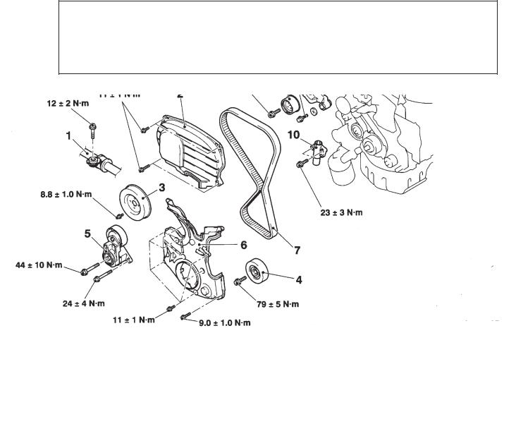
Removal procedure
1.Pressure hose connection
2.Timing belt front upper cover
3.Water pump pulley
4.Idler pulley
5.Drive belt auto-tensioner
6.Timing belt front lower cover
• Remove the engine mount bracketG • Adjust the tension of the timing belt
<Only after fitting>A F 7. Timing belt
E 8. Tensioner pulley
9.Tensioner arm
D 10. Auto-tensioner

ENGINE – TIMING BELT, TIMING BELT B |
11-21 |
(engine oil)
|
10. |
Power steering oil pressure switch connector |
C C 16. |
Crankshaft sprocket |
|
11. |
Heat protector |
C 17. |
Crankshaft sensing blade |
B |
12. |
Power steering oil pump ASSY |
B • |
Adjust the tension of the timing belt B |
|
13. |
Power steering oil pump bracket |
A 18. |
<Only after fitting> |
|
14. |
Idler pulley |
Timing belt B tensioner |
|
|
15. |
Crank angle sensor |
D A 19. |
Timing belt B |
Timing marks
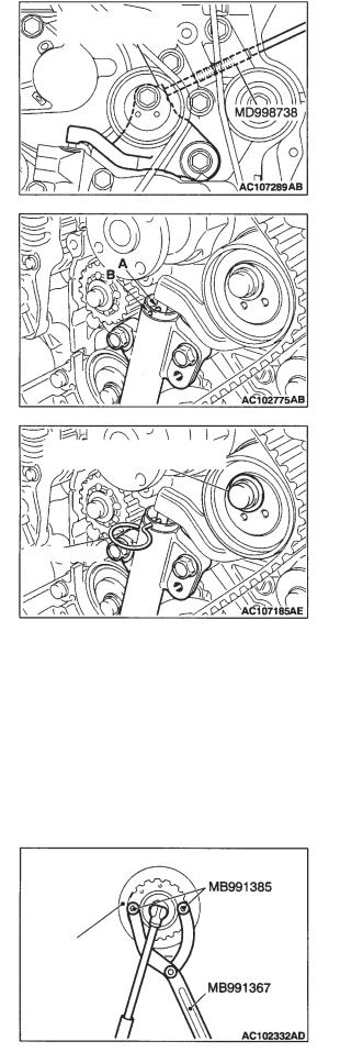
Removal guidelines
A Removing the timing belt
1.Turn the crankshaft in a clockwise direction, and match up all the timing marks until the No.1 cylinder is in the compressor top dead centre position.
Caution
Turn the crankshaft in the normal way.
2.Remove the rubber plug from the rear cover of the timing belt, and prepare the special tool for adjusting bolts (MD998738).
Timing belt valence
11-22 |
ENGINE – TIMING BELT, TIMING BELT B |
timing belt tensioner arm
bolt for fitting the timing belt tensioner
wire or pin
3.Twist the special tool for adjusting bolts (MD998738) by hand until it touches the tensioner arm.
Caution
The special tool for adjusting bolts (MD998738) can be slowly twisted at a rate of about 30° per second but if it is suddenly twisted the auto-tensioner rod cannot be easily withdrawn, and this may lead to problems with twisting and the possibility that the special tool for adjusting bolts (MD998738) may become bent.
4.Twist the special tool for adjusting bolts (MD998738) a little, and align the auto-tensioner rod with setting hole A, and the tensioner cylinder with setting hole B.
5.Insert a wire or a pin into the aligned holes.
6.Remove the special tool for adjusting bolts (MD998738), and then loosen the bolt for fitting the timing belt tensioner, and remove the timing belt.
Caution
If a timing belt is being re-used, check and make a note of the direction of the arrows indicating the rotational direction (clockwise direction) on the back of the belt.
B Removing the power steering oil pump ASSY
Remove the power steering oil pump ASSY from its bracket, with the hose intact.
Note
Secure the removed power steering oil pump ASSY with string, and put it somewhere where it will not hinder the removal or fitting of the timing belt.
C Removing the crankshaft sprocket
1.Hold the crankshaft sprocket in place using the special spanner (MB991367) and the special pin (MB991385).
2.Remove the crankshaft sprocket.
Crankshaft sprocket

ENGINE – TIMING BELT, TIMING BELT B |
11-23 |
timing marks
side of belt under tension
timing marks
balancer shaft sprocket
crankshaft sprocket
centre of the pulley
centre of the mounting bolt
D Removing timing belt B
Caution
If planning to re-use a timing belt B, ensure that it will be refitted the same way round, by marking the back of the belt with chalk arrows indicating the direction of movement.
Fitting guidelines
A Fitting timing belt B and the timing belt B tensioner
1.Check that the timing marks for the crankshaft sprocket and the balancer shaft sprocket are aligned.
2.Fit timing belt B onto the crankshaft sprocket and the balancer shaft sprocket. Ensure that the side of the belt under tension is not slack.
3.As a temporary step, fit the timing belt B tensioner pulley so that its centre is to the upper left of the centre of the mounting bolt, and so that the flange of the pulley is facing towards the front of the engine.
4.Adjust the tension of timing belt B.
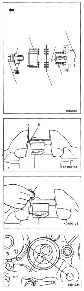
B Adjusting the tension of timing belt B
1.Hold the timing belt B tensioner between fingertips and in the direction of the arrows, apply tension torque (3.0 ± 0.4 N·m) to timing belt B until the side of the belt under tension becomes taught. In this condition, tighten the mounting bolt to the specified torque, and fit the tensioner.
Tightening torque: 19 ± 3 N·m Caution
When tightening the mounting bolt, ensure that the tensioner does not turn round with it. If the tensioner turns with the mounting bolt, it could cause the tension in the belt to become too high.

11-24 |
ENGINE – TIMING BELT, TIMING BELT B |
approx. 100 N
amount of give
pull lightly with fingertips
2. <Measuring the amount of give>
(1)As shown in the diagram, apply a force of about 100N to the middle of the belt between the sprockets (indicated by the arrow), and check that the amount of give is as specified.
Specified values:
<when adjusted> 5~7mm <when replaced> 5~7mm
(2)If the specified values are not met, readjust the tension of the belt.
3. <When using MUT-II/III>
(1)Connect the special belt tension meter set (MB991668) to the MUT-II/III.
(2)Connect the special battery harness (MB991704) to the MUTII/III, and also connect it to the batteries.
(3)Give the crankshaft two turns in a clockwise direction, and check that the No.1 cylinder is in the top dead centre position, and that the timing marks on each sprocket are aligned.
(4)Select the “belt tension measurement” option from the display on the MUT-II/III.
(5)As shown in the diagram hold the special belt tension meter set (MB991668) in the middle of the belt between the sprockets (indicated by the arrow), 10~20mm away from the outer side of the belt and vertically to the belt (not leaning more than ±15° away from vertical).
(6)As shown in the diagram, lightly pull the middle of the belt between the sprockets (indicated by the arrow) using fingertips and check that the vibration frequency of the belt is within the limits specified.
Specified values: 76 ~ 92 Hz Caution
(1)The meter may give an incorrect reading if the microphone is affected by a strong wind, or if there are loud noises nearby, while testing is taking place.
(2)The meter may give an incorrect reading if testing is performed while the microphone is touching the belt.
(7)If the specified values are not met, readjust the tension of the belt.
ENGINE – TIMING BELT, TIMING BELT B |
11-25 |
|
Front of engine |
|
|
|
|
|
|
|
|
|
|
|
|
|
|
|
|
|
|
|
crankshaft |
|
|
|
|
|
|
|
|
|
|
|
crankshaft sprocket |
|
|
|
|
|
|
|
|
|
|
|
|
|
|
|
|
|
|
|
|
|
|
|
|
|
|
clean |
|
||
washer |
|
|
here |
|
|
||
|
|
|
remove |
|
|
|
|
grease |
|
|
|
|
|
|
|
|
|
|
|
crankshaft bolt |
|
|
|
|
|
crankshaft |
|
||
|
|
|
||
|
|
sensing |
|
|
|
|
blade |
|
|
|
|
|
|
|
|
|
|
|
|
wire or pin
C Fitting the crankshaft sensing blade and the crankshaft sprocket
1.Clean, and remove any grease from the crankshaft sensing blade, the crankshaft sprocket, and the surface of the crankshaft to which the crankshaft sprocket will be fitted.
2.Fit the crankshaft sensing blade and the crankshaft sprocket in the direction shown in the diagram.
3.Clean the screw hole in the crankshaft.
4.Place the washer with the larger surface side in the direction as shown in the diagram, and fit it to the crankshaft bolt.
5.Apply a small quantity of engine oil to the top and to the screw thread parts of the crankshaft bolt.
6.In the same way as when it was removed, hold the crankshaft sprocket using the special tool, and tighten the crankshaft bolt to the specified torque.
Tightening torque: 167 N·m
D Fitting the auto-tensioner
1.If the auto-tensioner rod remains in an extended state, install it using the following procedure.
(1)Using a press or a vice, slowly compress the autotensioner rod and align the rod with setting hole A and the tensioner cylinder with setting hole B.
Caution
If the speed of compression is too fast, there is a chance that the rod may break, so carry out this operation slowly.
(2)Insert a wire or pin into the aligned holes. Note
If a brand new or a replacement auto-tensioner is being used, use a pin to set the auto-tensioner in place.
2.Fit the auto-tensioner into the engine and tighten the mounting bolt to the specified torque. Do not remove the wire or pin until the tension of the timing belt has been adjusted.
Tightening torque: 23 ± 3 N·m
E Fitting the tensioner pulley
As a temporary step, fit the tensioner pulley as shown in the diagram.
tensioner pulley holes
 Loading...