


Lossnay LGH-50RX3
Mitsubishi Electric Lossnay LGH-50RX3, Lossnay LGH-100RX3-50, Lossnay LGH-25RX3, Lossnay LGH-35RX3, Lossnay LGH-150RX3 Technical Manual
...
TECHNICAL MANUAL

i
CONTENTS
CHAPTER 1 Ventilation for Healthy Living
1. Necessity of Ventilation ...................................................................................................................................... 2
2. Ventilation Standards .......................................................................................................................................... 4
3. Ventilation Method .............................................................................................................................................. 5
4. Ventilation Performance ...................................................................................................................................... 8
5. Outdoor Air (ventilation) Load .............................................................................................................................. 10
CHAPTER 2 Lossnay Construction and Principle
1. Construction and Features of Lossnay .............................................................................................................. 16
2. Construction and Principle of Core ...................................................................................................................... 16
3. Calculation of the Total Heat Recovery Efficiency .............................................................................................. 18
4. What is a Psychrometric Chart? ........................................................................................................................ 19
5. Calculation of Lossnay Heat Recovery .............................................................................................................. 20
CHAPTER 3 General Technical Considerations
1. Lossnay Heat Recovery Effect ............................................................................................................................ 22
2. Example Heat Recovery Calculation .................................................................................................................. 24
3. Calculation of Lossnay Economical Effects ........................................................................................................ 26
4. Psychrometric Chart .......................................................................................................................................... 28
5. The Result of No Bacerial Cross Contamination for the Lossnay Core and Determining
Resistance of the Lossnay Core to Molds .......................................................................................................... 29
6. Flame-proofing Properties of Lossnay Core ...................................................................................................... 31
7. Lossnay Core’s Soundproofing Properties Test .................................................................................................. 33
8. Change in Lossnay Core Over Time .................................................................................................................. 34
9. Comparison of Heat Recovery Techniques ........................................................................................................ 36
CHAPTER 4 Characteristics
1. How to Read the LGH Series Lossnay Characteristic Curves ............................................................................ 40
2. Obtaining the Static Pressure Loss .................................................................................................................... 40
3. How to Obtain Efficiency from Characteristic Curves ........................................................................................ 44
4. Sound .................................................................................................................................................................. 45
5. NC Curves (LGH-RX
3 Series) ............................................................................................................................ 51
6. List of Models ...................................................................................................................................................... 55
CHAPTER 5 System Design Recommendations
1. Lossnay Usage Conditions ................................................................................................................................ 60
2. Noise Value of Lossnay with Built-in Fans .......................................................................................................... 61
3. Attachment of Air Filter ...................................................................................................................................... 61
4. Duct Construction .............................................................................................................................................. 61
5. By-pass Ventilation ............................................................................................................................................ 61
6. Transmission Rate of Various Gases and Related Maximum Workplace Concentration .................................. 62
7. Solubility of Odors and Toxic Gases, etc., in Water and Effect on Lossnay Core .............................................. 63
8. Positioning of the Supply/Exhaust Fans and the Air Transmission Rate
(excluding moisture resistant total heat recovery units) ...................................................................................... 64
9. Combined Operation with other Air Conditioners ................................................................................................ 65
10. Automatic Ventilation Switching .......................................................................................................................... 66
11. Vertical Installation of LGH Series ...................................................................................................................... 67
12. Installation of Supplementary Fan Devices After Lossnay Unit .......................................................................... 68

ii
CHAPTER 6 Examples of Lossnay Applications
1. Large Office Building .......................................................................................................................................... 70
2. Medium Size Office Building .............................................................................................................................. 73
3. Multipurpose Tenant Building .............................................................................................................................. 76
4. Urban Small-Scale Building ................................................................................................................................ 79
5. Hospitals ............................................................................................................................................................ 80
6. Schools .............................................................................................................................................................. 82
7. Hotels (convention halls, wedding halls) ............................................................................................................ 84
8. Public Halls (combination facilities such as day-care centres) ............................................................................ 85
CHAPTER 7 Installation Considerations
1. LGH-Series Lossnay Ceiling Embedded-Type (LGH-RX3 Series) ...................................................................... 88
2. Business Lossnay Suspended Exposed-Type .................................................................................................... 91
3. Building Lossnay Pack-type (LP-200B, 350B · 500B · 750B · 1000B) ................................................................ 92
4. Building Lossnay Unit Vertical-type (LUT-2302 · 2303 · 3002 · 3003) ................................................................ 95
5. Building Lossnay Unit Horizontal-type (LU-80 · 160 · 500) ................................................................................ 97
6. Industrial Moisture Resistant Lossnay (LUP-80 · 160 · 500) .............................................................................. 100
CHAPTER 8 Filtering for Freshness
1. Necessity of Filters .............................................................................................................................................. 104
2. Data Regarding Dust .......................................................................................................................................... 104
3. Calculation Table for Dust Collection Efficiency of Each Lossnay Filter ............................................................ 105
4. Comparison of Dust Collection Efficiency Measurement Methods .................................................................... 107
5. Calculation of Dust Concentration ...................................................................................................................... 109
CHAPTER 9 Service Life and Maintenance
1. Service Life ........................................................................................................................................................ 112
2. Cleaning the Lossnay Core and Pre-filter .......................................................................................................... 112
CHAPTER 10 Ventilation Standards in Each Country
1. Ventilation Standards in Each Country ................................................................................................................ 114
2. U.S. ...................................................................................................................................................................... 125
3. U.K. ...................................................................................................................................................................... 125
CHAPTER 11 Lossnay Q and A

CHAPTER 1
Ventilation for Healthy Living
2
CHAPTER 1 ● Ventilation for Healthy Living
Fresh outdoor air must be introduced constantly at a set ratio in an air conditioning system. This fresh air is introduced to be
mixed with the return air from the room, to adjust the temperature and humidity, supply oxygen, reduce body and other odors,
remove tobacco smoke and to increase the cleanness of the air.
The standard ventilation (outdoor air intake) volume is determined according to the type of application, estimated number of
persons in the room, room area, and relevant regulations. Systems which accurately facilitate these requirements are
increasingly being required to be installed in buildings.
1. Necessity of Ventilation
The purpose of ventilation is basically divided into “oxygen supply”, “cleaning of air”, “temperature control” and “humidity
control”. Cleaning of the air includes the elimination of “odors”, “gases”, “dust” and “bacteria”. The needs of ventilation are
divided into “personal comfort”, “assurance of environment for animals and plants”, and “assurance of environments for
machinery and constructed materials”.
In Japan legal regulations regarding ventilation are set in the Building Srandard Law Enforcement Ordinance and the “Building
Management Law” for securing a sanitary environment in buildings. These are in general agreeance with similar regulations in
other countries.
1.1 Room air environment in buildings
In Japan, the Building Management Law, a law concerning the sanitary environment of buildings, designates eleven
applications including offices, shops, and schools with a total floor area of 3,000 m
2
or more, as buildings. According to this
law maintenance and management of the ventilation and water supply and discharge according to the Environmental
Sanitation Management Standards is obligatory.
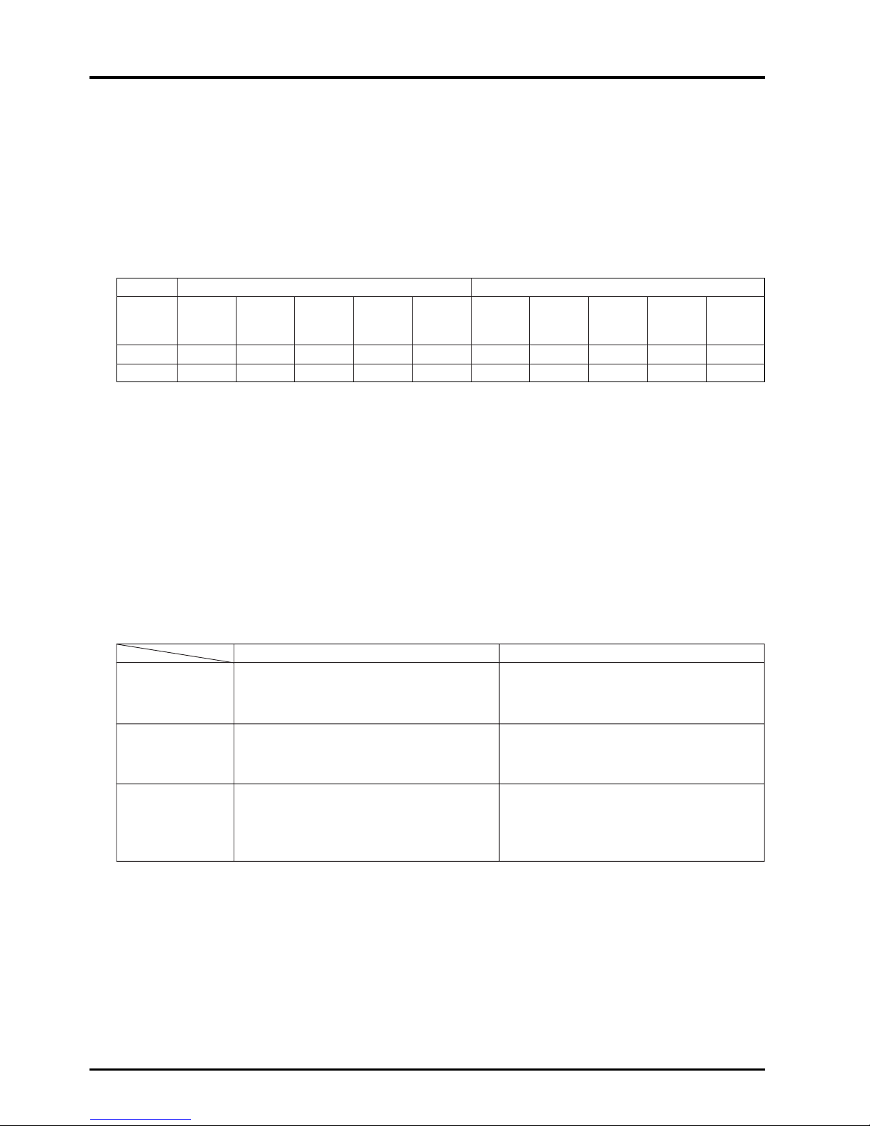
The following table gives a specific account of buildings in Tokyo.
(Tokyo Food and Environment Guidance Center Report)
Specific Account of Buildings in Tokyo (March, 1993)
Number of buildings %
Offices 2,346 65.4
Shops 344 9.6
Department Stores 73 2.0
Schools 388 10.8
Inns 164 4.6
Theaters 84 2.3
Libraries 30 0.8
Museums 15 0.4
Assembly Halls 95 2.6
Art Museums 7 0.2
Amusement Centers 42 1.2
Total 3,588 100.0
Note: Excludes buildings with an expanded floor space of 3,000 to 5,000 m2in particular areas.
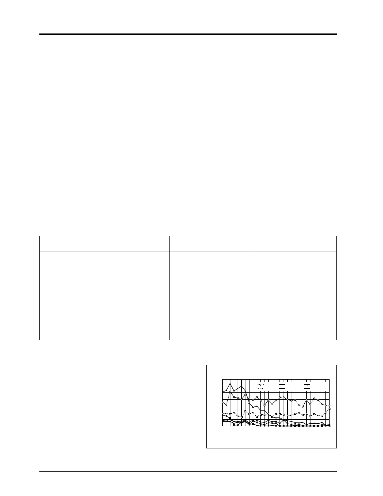
The ratio of results of the air quality measurement public
inspection and the standard values that were not met (percentage
of unsuitability) for the approximately 500 buildings examined in
1980 is shown in the chart at the right.
There was a large decrease in unsuitable percentages of floating
particles, but there was almost no change in temperature and
carbon dioxide. Values for temperature, ventilation, and carbon
monoxide almost entirely cleared the standard values, and are
excluded. The study from 1989 shows the item with the highest
percentage of unsuitability as temperature with 37%, followed by
carbon dioxide at 15%.
76 77 78 79 80 8171 72 73 74 75
82
83 84
85
86
87
88
899091 92 93 94 95 96 97 98 99
70
60
50
40
30
20
10
0
relative humidity
carbon dioxide
temperature
carbon monoxide
ventilation
floating particles
Percentage of unsuitability (%)
Percentage of unsiutability of air quality by year
(according to the Tokyo Food and Environment Guidance Center)
3
CHAPTER 1 ● Ventilation for Healthy Living
Effect of carbon monoxide (CO) 10,000 ppm = 1%
Concentration (ppm)
Effect of concentration changes
0.01 - 0.2 Standard atmosphere.
5 Considered to be the long-term tolerable value.
10
The Building Standard Law of Japan, Law for Maintenance of Sanitation in Buildings.
Environmental standard 24-hour average.
20
Considered to be the short-term tolerable value.
Environmental standard 8-hour average.
50
Tolerable concentration for labor environment.
(Japan Industrial Sanitation Association)
100
No effect for 3 hours. Effect noticed after 6 hours.
Headache, illness after 9 hours; harmful for long-term but not fatal.
200 Light headache in the forehead in 2 to 3 hours.
400 Headache in the forehead, nausea in 1 to 2 hours; headache in the back of head in 2.5 to 3 hours.
800 Headache, dizziness, nausea, convulsions in 45 minutes. Comatose in 2 hours.
1,600 Headache, dizziness in 20 minutes. Death in 2 hours.
3,200 Headache, dizziness in 5 to 10 minutes. Death in 30 minutes.
6,400 Death in 10 to 15 minutes.
12,800 Death in 1 to 3 minutes.
Several 10,000 ppm
This level may be found in automobile exhaust.
(Several %)
Apprpx. 5 ppm is
an annual
average value in
city areas.
This value may
exceed 100 ppm
near roads, in
tunnels and
parking areas.
Concentration (%) Standards and effect of concentration changes
Approx. 21 Standard atmosphere.
20.5
Ventilation air volume standard will be a guideline where concentration does not decrease more than 0.5%
from normal value. (The Building Standard Law of Japan)
20 - 19
An oxygen deficiency of this amount does not directly endanger life in a normal air pressure, but if there is a
combustion device in the area, the generation of CO will increase rapidly due to incomplete combustion.
18 Industrial Safety and Health Act. (Hypoxia prevention regulations.)
16 Normal concentration in exhaled air.
16 - 12 Increase in pulse and breathing resulting in dizziness and headaches.
15 Flame in combustion devices will extinguish.
12 Threat to life in short term.
7 Fatal
In the case of Japan, an Instruction Guideline based on these regulations has been issued, and unified guidance is carried out.
Part of the Instruction Guideline regarding ventilation is shown below.
●
The fresh outdoor air intake must be 10 m or higher from ground level, and be distanced appropriately from the exhaust air
outlet. (Neighbouring buildings must also be considered.)
●
The fresh outdoor air intake volume must be 25 to 30 m3/h·person in design.
●
An air volume measurement hole must be installed at an effective position to measure the treated air volume of the
ventilating device.
●
The position and shape of the supply diffuser and return grille must be selected so the air environment in the room is
distributed evenly.
1.2 Effect of air contamination on human bodies
Effect of oxygen (O
2) concentration

4
CHAPTER 1 ● Ventilation for Healthy Living
Effect of carbon dioxide (CO2)
Note: According to Facility Check List published by Kagekuni-sha.
1.3 Effect of air contamination in buildings
●
Dirtiness of interior
New ceilings, walls and ornaments will turn yellow in one to two years. This is caused by dust and the tar in tobacco smoke.
2. Ventilation Standards
The legal standards for ventilation differ according to each country. Please follow the standards set by the country. In the US,
Ashrae revised their standards in 1989 becoming more strict.
In Japan, regulations are set in the The Building Standard Law of Japan Enforcement Ordinance, the so-called “Building
Management Law” for securing a sanitary environment in buildings. According to the Building Standards Law, a minimum of
20 m
3
/h per person of ventilation air is required.
Concentration (%) Effect of concentration changes
0.03 (0.04) Standard atmosphere.
0.04 - 0.06 City air.
0.07 Tolerable concentration when many people stay for long time.
0.10
General tolerable concentration.
The Building Standard Law of Japan, Law for Maintenance of Sanitation in Buildings.
0.15 Tolerable concentration used for ventilation calculations.
0.2 - 0.5 Observed as relatively poor.
0.5 or more Observed as the poorest.
0.5 Long-term safety limits (U.S. Labor Sanitation) ACGIH, regulation of laborer offices.
2 Depth of breathing and inhalation volume increases 30%.
3 Work and physical functions deteriorate, breathing doubles.
4 Normal exhalation concentration.
4 - 5
The respiratory center is stimulated; depth and times of breathing increases. Dangerous if breathed in for a
long period. If an O
2 deficiency also occurs, trouble will occur sooner and be more dangerous.
8
When breathed in for 10 minutes, breathing difficulties, redness in the face and headaches will occur.
The trouble will worsen when there is also a deficiency of O
2.
18 or more Fatal
There is no toxic level in
CO2 alone.
However, these tolerable
concentrations are a
guideline of the
contamination estimated
when the physical and
chemical properties of
the air deteriorate in
proportion to the
increase of CO2
.
5
CHAPTER 1 ● Ventilation for Healthy Living
3. Ventilation Method
3.1 Ventilation class and selection points
An appropriate ventilation method must be selected according to the purpose.
Ventilation is composed of “Supply air” and “Exhaust air” functions. These functions are classified according to natural flow or
mechanical ventilation using a fan (forced ventilation).
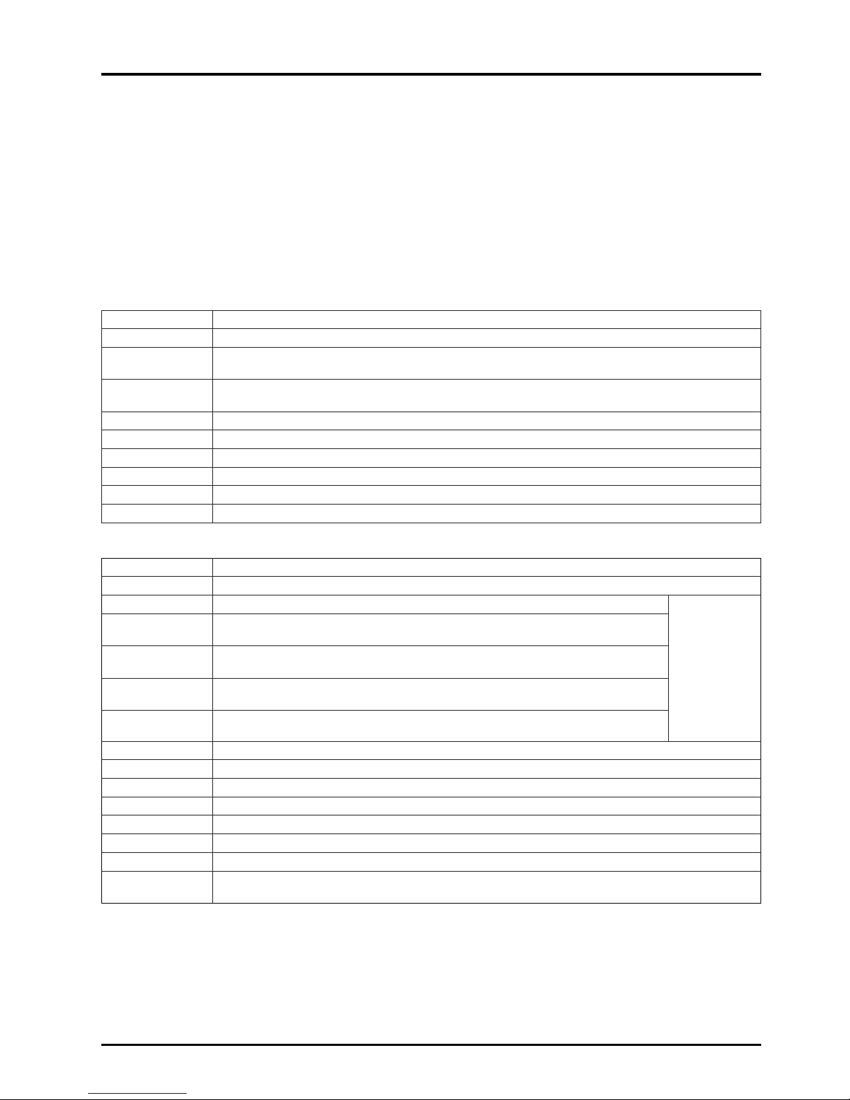
Classification of mechanical ventilation
Classification of ventilation (according to Building Standards Law)
1. Class 1 ventilation
Fresh outdoor air is mechanically
brought in and simultaneously the
stale air in the room is mechanically
discharged.
2. Class 2 ventilation
Fresh outdoor air is mechanically
brought in and the exhaust air is
discharged from the exhaust air
outlet (natural).
3. Class 3 ventilation
The stale air in the room is
mechanically discharged and
simultaneously fresh outdoor air is
mechanically introduced from the
supply air diffuser (natural).
Ex. of application
• Ventilation of air
conditioned rooms.
(buildings, hospitals,
etc.)
• Ventilation of room
not facing an outer
wall. (basement,
etc.)
• Ventilation of large
room. (office, large
conference room,
hall, etc.)
• Surgery theatre.
• Clean rooms.
• Foodstuff processing
factories.
• Local ventilation in
kitchens.
• Ventilation of hot
exhaust air from
machine room, etc.
• Ventilation of humid
exhaust air from
indoor pools, bathrooms, etc.
• General simple
ventilation.
System effect
By changing the
balance of the supply
fan and exhaust fan’s
air volumes, the
pressure in the room
can be balanced
freely, and the
interrelation with
neighboring spaces
can be set freely.
As the room is
pressurized, the flow
of odors and dust,
etc., from neighboring
areas can be
prevented.
The exhaust air is
removed from a local
position in the room,
and dispersion of the
stale air can be
prevented by applying
an entire negative
pressure.
Design and construction
properties
•
An ideal design in which
the supply air diffuser
and exhaust air outlet
position relation and air
volume, etc., can be set
freely is possible.
• A system which adjusts
the temperature and
humidity of the supply
air diffuser flow to the
room environment can
be incorporated.
•
The supply and
exhaust volume can be
set freely according to
the changes in
conditions.
• The position and
shape of the supply
air diffuser can be
set.
• The temperature and
humidity of the
supply air diffuser
flow can be set
accordingly, and
dust can be removed
as required.
• Effective exhausting
of dispersed stale air
generation sites is
possible from a local
exhaust air outlet.
• Ventilation in which
the air flow is not felt
is possible with the
supply air diffuser
setting method.
Selection points
• Accurate supply air
diffuser can be
maintained.
• The room pressure
balance can be
maintained.
• The supply air
diffuser temperature
and humidity can be
adjusted and dust
treatment is
possible.
• The pressure is
positive.
•
The supply air diffuser
temperature and
humidity can be
adjusted, and dust
treatment is possible.
•
The positional relation
of the exhaust air
outlet to the supply air
diffuser is important.
• The room pressure
is negative.
• Local exhaust is
possible.
• Ventilation without
dispersing stale air is
possible.
• Ventilation with
reduced air flow is
possible.
•
The positional relation
of the exhaust air
outlet to the supply air
diffuser is important.
Supply
air
diffuser
Exhaust
fan
Exhaust
air
outlet
Exhaust
fan
Exhaust
fan
Stale
air
Fresh
outdoor
air
Supply Exhaust Ventilation volume Room pressure
Class 1 Mechanical Mechanical Random (constant) Random
Class 2 Mechanical Natural Random (constant) Positive pressure
Class 3 Natural Mechanical Random (constant) Negative pressure
Class 4 Natural Mechanical & natural Limited (inconstant) Negative pressure
1) System operation with cassette-type air conditioner
2) System operation with ceiling embedded-type air conditioner
3) Independent operation with ceiling suspended-type air conditioner
6
CHAPTER 1 ● Ventilation for Healthy Living
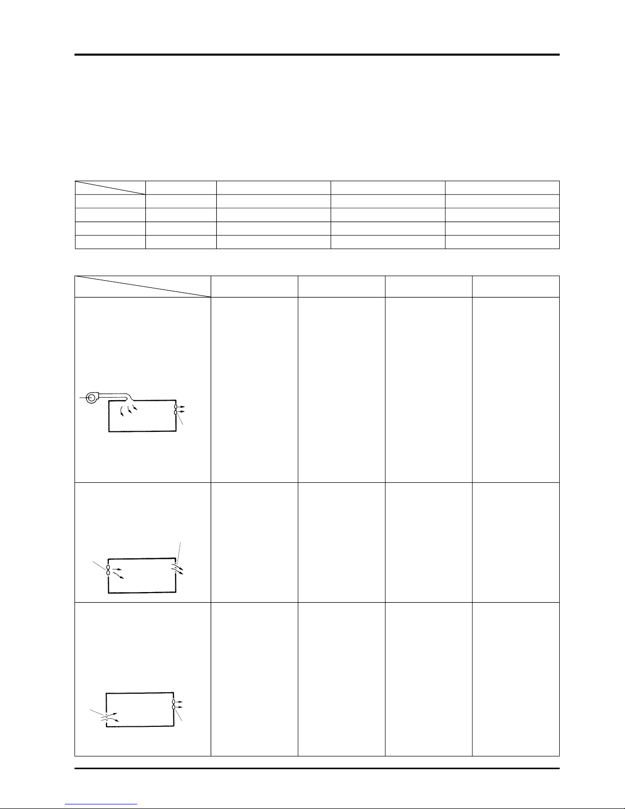
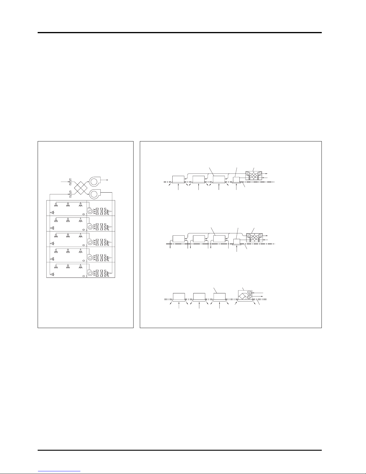
3.2 Comparison of ventilation methods
There are two main types of ventilation methods.
Centralized ventilation method
This is mainly used in large buildings, with the fresh outdoor air intake being installed in one machine room. For this method,
primary treatment of the fresh outdoor air, such as heat recovery to the intake air and dust removal is performed being
distribution to the building by ducts.
Independent zoned ventilation method
This is mainly used in small to medium sized buildings, with areas being ventilated using fresh outdoor air intakes formed of
independent ventilation devices. The rate of use of this method has recently increased as independent control is becoming
ever more feasible.
Centralised ventilation method Independent zoned ventilation method
Air intake
(fresh out-
door air)
Filters
Air exhaust
(stale air)
Cassette-type package air
conditioner or fan coil unit
Cassette-type or ceiling suspended-type
package air conditioner or fan coil unit
Ceiling-mounted type Lossnay or
ceiling embedded-type Lossnay
Exhaust grill
Ceiling recessedtype Lossnay
Exhaust air
Fresh outdoor air
Finished ceiling
Fresh outdoor air
Exhaust air
Finished ceiling
Lossnay
Supply fan
Exhaust
Each unit
Ceiling embedded-type package
air conditioner or fan coil unit
Ceiling recessedtype Lossnay
Exhaust grill
Exhaust air
Fresh outdoor air
Finished ceiling

7
CHAPTER 1 ● Ventilation for Healthy Living
Comparison of centralised ventilation method and independent zoned ventilation method
Centralized ventilation method
The air transfer distance is long thus requiring
much fan power.
• Independent equipment room is required.
• Duct space is required.
• Penetration of floors with vertical shaft is not
desired in terms of fire prevention.
Generalized per system.
• Design of outer wall is not lost.
• The indoor supply air diffuser and return grille
can be selected freely for an appropriate design.
As there are many common-use areas, if the
building is a tenant building, an accurate
assessment of operating cost is difficult.
• As the usage time setting and ventilation volume
control, etc., is performed in a central monitoring
room, the user’s needs may not be met
appropriately.
• A large amount of ventilation is required even for
a few persons.
• An ideal supply air diffuser and return grille
position can be selected as the supply air
diffuser and return grilles can be laid out freely.
• The only noise in the room is the aerodynamic
sound.
• Anti-vibration measures must be taken as the
fan in the equipment room is large.
• Centralized management is easy as it can be
performed in the equipment room.
• The equipment can be inspected at any time.
• Large as the entire system is affected.
• Immediate inspection can be performed in the
equipment room.
Fan power
Installation space
Zoning
Designability
Clarification of costs
Controllability
Comfort
Maintenance and
management
Trouble correspondence
Independent zoned ventilation method
As the air transfer distance is short, the fan power
is small.
• Independent equipment room is not required.
• Piping space is required only above the ceiling.
Can be utilised for any one area.
• The number of intakes and exhaust air outlets
on the outer wall will increase; design must be
considered.
• The design will be fixed due to the installation
fittings, so the design of the intakes and exhaust
air outlets must be considered.
Invoicing for each zone separately is possible,
even in a tenant building.
• The user in each zone can operate the ventilator
freely.
• The ventilator can be operated even during offpeak hours.
• Consideration must be made of the noise from
the main unit.
• Anti-vibration measures are often not required
as the unit is compact and the vibration
generated can be dispersed.
• Work efficiency is poor as the equipment is not
centrally located.
• An individual unit can be inspected only when
the room it serves is vacant.
• Limited as only independent units are affected.
• Consultation with the tenant is required prior to
inspection of an individual unit.

8
CHAPTER 1 ● Ventilation for Healthy Living
4. Ventilation Performance
The ventilation performance is largely affected by the installation conditions. Ample performance may not be achieved unless
the model and usage methods are selected according to the conditions.
Generally, the ventilation performance is expressed by “Air volume” and “wind pressure (static pressure)”, and these are
necessary when considering ventilation.
4.1 Air volume
Air volume expresses the volume of air exhausted (or supplied) by the unit in a given period. Generally, this is expressed as
m
3
/hr (hour).
4.2 Wind pressure
When a piece of paper is placed in front of a fan and let go, the piece of paper will be blown away. The force that blows the
paper away is called the wind pressure, and this is normally expressed in units of mmH2O or mmAq {Pa (Pascal) in SI unit
system: 1 mmH2O = approx. 9.8Pa}. The wind pressure is divided into the following three types:
4.2.1 Static pressure
This is the force that presses the surroundings when the air is still such as in an automobile tyre or rubber balloon. For
example, in a water gun, the hydraulic pressure increases when pressed by a piston, and if there is a small hole, the water
sprays out with force. The pressure of this water is equivalent to the static pressure for air. The higher the pressure is, the
further the water (air) can be sprayed.
4.2.2 Dynamic pressure
This expresses the speed at which air flows, and can be thought of as the force at which a typhoon presses against a building.
4.2.3 Total pressure
This is the total force that wind has, and is the sum of the static pressure and dynamic pressure.
9
CHAPTER 1 ● Ventilation for Healthy Living
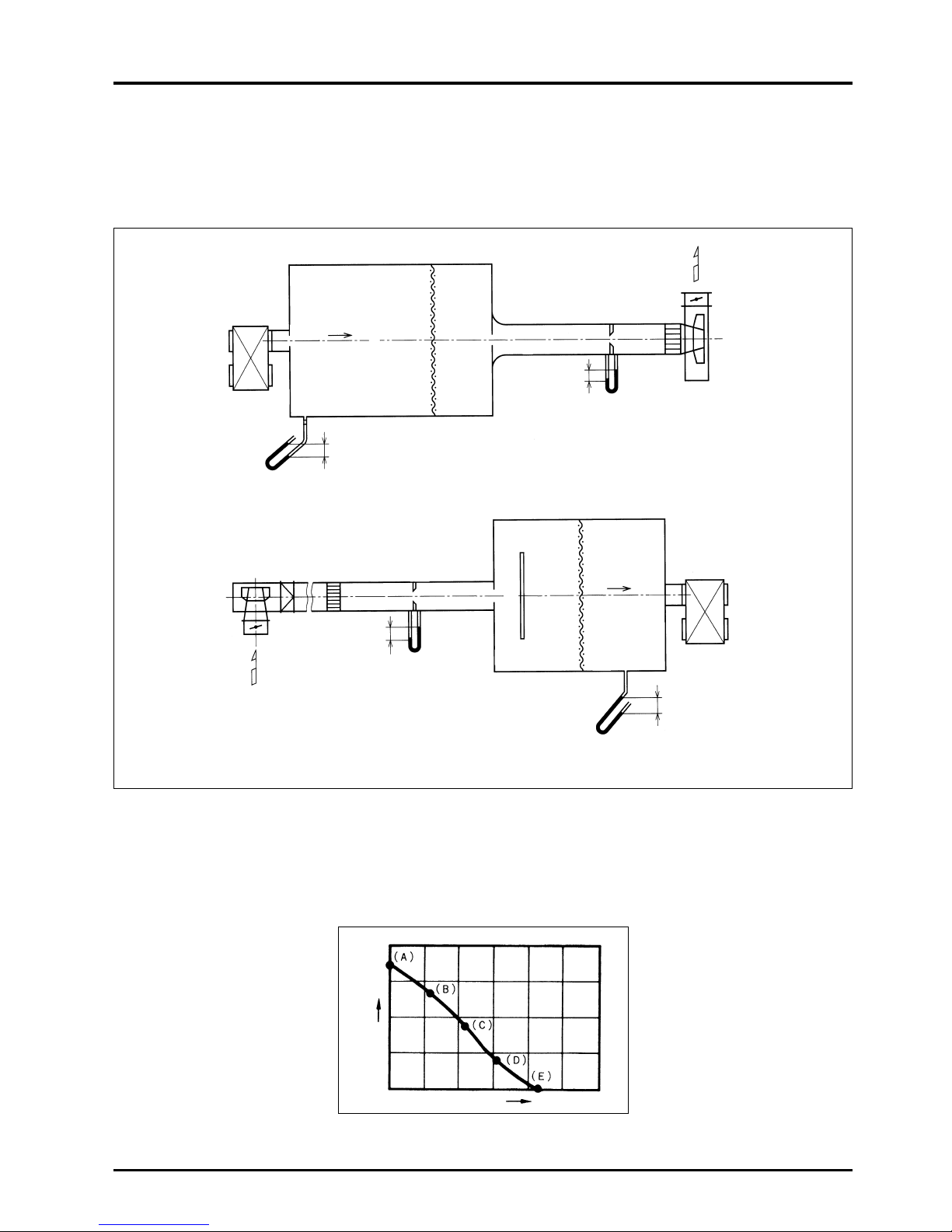
4.3 Measurement of the air volume and wind pressure
Mitsubishi measures the machine’s air volume and wind pressure with a device as shown below according to the Japan
Industrial Standards (JIS B 8628).
Measuring device using orifice (JIS B 8628 standards)
Static pressure (
H
)
Air volume (Q)
Measurement method
The unit is operated with the throttle device fully closed. There is no air flow at this time, and the air volume is 0. The maximum
point of the static pressure (A point, the static pressure at this point is called the totally closed pressure) can be obtained. Next,
the throttle device is gradually opened, the auxiliary fan is operated, and the middle points (points B, C and D) are obtained.
Finally, the throttle device is completely opened, and the auxiliary fan is operated until the static pressure in the chamber
reaches 0. The maximum point of the air volume (point E, the air volume at this point is called the fully opened air volume) is
obtained. The points are connected as shown below, and are expressed as air volume, static pressure curves (Q-H curve).
Connection
Wind dispersing place
Connection
Rectifying
grid
Rectifying
grid
Supply
Air
(SA)
Chamber
Return
Air
(RA)
Rectifying
net
Rectifying
net
Wind gauge
duct path
Orifice
Wind gauge
duct path
Orifice
Damper
Blower
Blower
Test unit
Test unit
Static pressure in chamber
(Static pressure measurement)
Static pressure in chamber
(Static pressure measurement)
Pressure
difference before
and after orifice
(Air volume
measurement)
A) When measuring the supply air volume (with the orifice plate)
B) When measuring the return air volume (with the orifice plate)
10
CHAPTER 1 ● Ventilation for Healthy Living
5. Outdoor Air (ventilation) Load
5.1 How to calculate each approximate load
The outdoor air load can be calculated with the following formula if the required outside air intake volume Q m3/h to be
introduced is known:
(Outdoor air load) = γ · QF · (iO - iR)
= γ [kg/m
3
] × S[m2] × k × n [person/m2] × Vf [m3/h·person] × (iO
- iR): ∆i [kJ/kg (kcal/kg)]
γ : Specific gravity of air - 1.2 kg/m
3
S : Building’s airconditioned area
k : Thermal coefficient; generally 0.7 - 0.8.
n : The average population concentration is the inverse of the occupancy area per person. If the number of persons in the
room is unclear, refer to the Floor space per person table below.
Vf : Outdoor air intake volume per person
Refer to the Required outdoor air intake volume per person table below.
iO : Outdoor air enthalpy - kJ/kg (kcal/kg’)
iR : Indoor enthalpy - kJ/kg (kcal/kg’)
Floor space per person table (m
2
)
(According to the Japan Federation of Architects and Building Engineers Associations)
Required outdoor air intake volume per person table (m
3
/h·person)
Caution
The application of this table to each type of room should be carefully considered in relation to the degree of smoking in
the room.
Office building
Department store, shop
Restaurant
Teatre or
Average Crowded Empty
cinema hall
General design 4 - 7 0.5 - 2 0.5 - 2 5 - 8 1 - 2 0.4 - 0.6
value
5 3.0 1.0 6.0 1.5 0.5
Application example
Required ventilation volume
Degree of smoking
Recommended value Minimum value
Broker’s office
Extremely heavy Newspaper editing room 85 51
Conference room
Quite heavy
Bar
51 42.5
Cabaret
Heavy
Office
25.5
17
Restaurant 20
Light
Shop
25.5 17
Department store
None
Theatre 25.5 17
Hospital room 34 25.5
Cooling load per unit area
When the volume of outdoor air per person is 25 m
3
/h, and the number of persons per 1 m2is 0.2, the cooling load will be
approximately 157.0 W/m
2
(135 kcal/h·m2).
How these values are determined can be seen as follows:
● Outdoor air load
Air conditions <Standard design air conditions in Tokyo>
11
CHAPTER 1 ● Ventilation for Healthy Living
Example calculations of determining ventilation load during both cooling and heating are given as follows:
5.2 Ventilation load during cooling (in general office building)
● Classification of cooling load
(a) is the heat infiltrating the room, and often is 30 to 40% of the entire cooling load.
(b) is the heat generated in the room.
(c) is applies only when reheating is necessary.
(d) is the heat generated when outdoor air is mixed into part of the supply air diffuser volume and introduced into the room.
The outdoor air is introduced to provide ventilation for the people in the room, and is referred to as the ventilating load.
Typical load values (during cooling)
Type of load Load
Outdoor air load 53.0 W/m
2
(45.6 kcal/h·m2)
Indoor
People 26.4 W/m
2
(22.7 kcal/h·m2)
generated heat
Lighting equipment 30.0 W/m
2
(25.8 kcal/h·m2)
Indoor infiltration heat 47.6 W/m
2
(40.9 kcal/h·m2)
Total 157.0 W/m
2
(135.0 kcal/h·m2)
Conditions: Middle floor of a general office building facing south.
Class
Heat from walls (q
WS)
(a) Indoor infiltration heat Heat from glass
from direct sunlight (qGS)
from conduction & convection (q
GS)
Accumulated heat load in walls (q
SS
)
Generated heat from people
Sensible heat (q
HS)
(b) Indoor generated heat
Latent heat (q
HL)
Genarated heat from electrical equipment Sensible heat (q
ES)
Latent heat (q
EL)
(c) Reheating load (q
RL)
(d) Outdoor air load
Sensible heat (q
FS)
Latent heat (qFL)
}
}
}
}
Dry bulb temp.
Relative humidity
Wet bulb temp. Enthalpy Enthalpy difference
Cooling
Outdoor air 33 °C 63% 27 °C 85 kJ/kg (20.3 kcal/kg’)
31.8 kJ/kg
Indoors 26 °C 50% 18.7 °C 53.2 kJ/kg (12.7 kcal/kg’)
(7.6 kcal/kg’)
When the load per floor area of 1 m2with a ventilation volume of 25 m3/h·person is calculated with the above air conditions, the
following is obtained:
Outdoor air (ventilation) load = 1.2 kg/m
3
(Specific gravity of air) × 0.2 persons/m2(no. of persons per 1 m2)
× 25 m
3
/h·person (outdoor air volume) × 31.8 kJ/kg (7.6 kcal/kg’) (air enthalpy difference indoors/outdoors)
= 190.8 kJ/h·m
2
(530 W/m2)
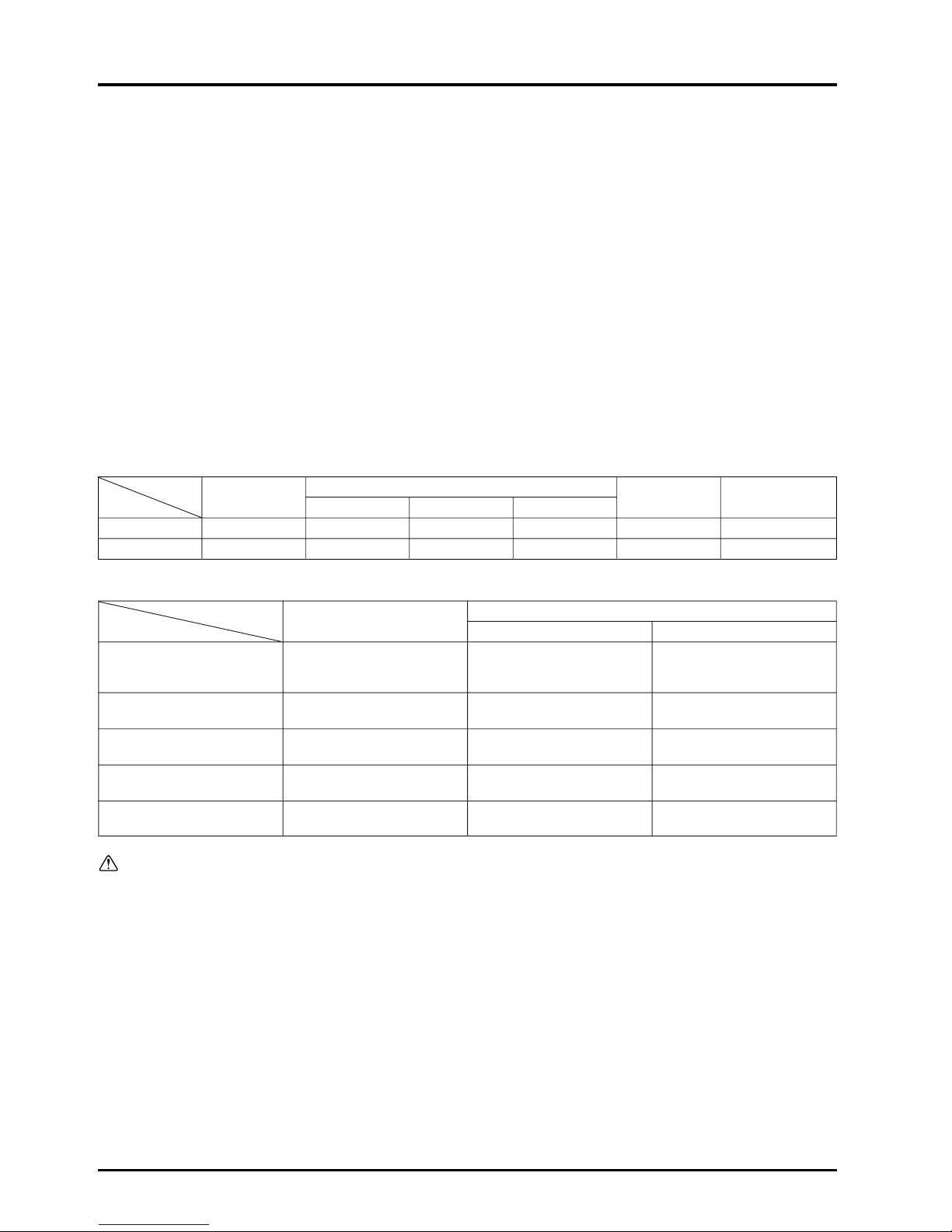
The Lossnay recuperates approximately 70% of the exhaust air load and saves on approximately 20% of the total load.
Outdoor air
load 33.8%
53.0 W/m
2
(45.6 kcal/h·m2)
Indoor
infiltration
heat 30.3%
47.6 W/m
2
(41.8 kcal/h·m2)
Indoor
generated heat
(people, lighting
equipment) 35.9%
56.4 W/m
2
156.5 W/m
2
(135.0 kcal/h·m2)

12
CHAPTER 1 ● Ventilation for Healthy Living
● Determining internal heat gain
When classifying loads, the internal heat gain (indoor generated heat + indoor infiltration heat) will be the value of the outdoor
air load subtracted from the approximate cooling load when it is assumed that there is no reheating load.
(Internal heat gain)
= 157.0 W/m
2
(135 kcal/h·m2) – 53.0 W/m2(45.6 kcal/h·m2) = 104.0 W/m2(89.4 kcal/h·m2)
●
This value of internal heat gain is based on assumptions for typical loads. To determine individual levels of internal heat
gain, the following is suggested:
● Indoor generated heat
(1) Heat generated from people
Heat generation design value per person in office
Sensible heat (SH)= 63.0 W·person (54 kcal/h·person)
Latent heat (LH) = 69.0 W·person (59 kcal/h·person)
Total heat (TH) = 132.0 W·person (113 kcal/h·person)
The heat generated per 1 m
2
of floor space is
(heat generated from people)
= 132.0 W·person (113 kcal/h·person) × 0.2 person/m
2
= 26.4 W/m2(22.6 kcal/h·m2)
(2) Heat generated from electrical equipment (lighting)
The approximate value of the room illuminance and power for lighting for a general office with illuminance of 300 350 Lux, is 20 - 30 W/m
2
.
● Indoor infiltration heat
This is the heat that infiltrates into the building from outside. This can be determined by subtracting the amount of heat
generated by people and lighting from the internal heat gain.
(Indoor infiltration heat)
= 104.0 – (26.4 + 30.0) = 47.6 W/m
2
(40.9 kcal/h·m2)
The Lossnay recuperates approximately 70% of the outdoor air load and saves on approximately 20% of the total load.
13
CHAPTER 1 ● Ventilation for Healthy Living
5.3 Ventilation load during heating
●
Classification of heating load
Class
Heat lost from walls (q
WS)
(a)
Indoor heat
Heat lost from glass (q
GS)
loss
Heat loss from conduction & convection (q
GS)
Accumulated heat load in walls (q
SS)
(b)
Outdoor air
Sensible heat (q
FS)
load
Latent heat (q
FL)
During heating, the heat generated by people and electrical equipment in the room can be subtracted from the heating load.
However, as the warming up time at the start of heating is short, this generated heat may be ignored in some cases.
Percentage of load
Internal heat loss
In terms of load classification, the internal heat loss is the value of the outdoor air load subtracted from the approximate
heating load.
Internal heat loss = 133.7 W/m
2
(115.0 kcal/h·m2) – 56.0 W/m2(48.2 kcal/h·m2) = 77.7 W/m2(66.8 kcal/h·m2)
Heating load per unit area
When the outdoor air volume per person is 25 m
3
/h, and the number of persons per 1 m2is 0.2 persons, the approximate
heating load will be approximately 133.7 W/m
2
(115 kcal/h·m2).
●
Outdoor air load
Air conditions <Standard design air conditions in Tokyo>
Type of load Load
Outdoor air load 56.0 W/m
2
(48.2 kcal/h·m2)
Internal heat 77.7 W/m
2
(66.8 kcal/h·m2)
Total 133.7 W/m
2
(115.0 kcal/h·m2)
Conditions: Middle floor of a general office building facing south.
Dry bulb temp.
Relative humidity
Wet bulb temp. Enthalpy Enthalpy difference
Heating
Outdoor air 0 °C 50% –3 °C 5.0 kJ/kg (1.2 kcal/kg’)
33.5 kJ/kg
Indoors 20 °C 50% 13.7 °C 38.5 kJ/kg (9.2 kcal/kg’)
(8.0 kcal/kg’)
When the load per 1 m2of floor area with a ventilation volume of 25 m3/h·person is calculated with the above air conditions, the
following is obtained:
Outdoor air (ventilation) load = 1.2 kg/m
3
× 0.2 persons/m2× 25 m3/h·person × 33.5 kJ/kg (8.0 kcal/kg’)
= 201.0 kJ/h·m
2
(56 W/m2)
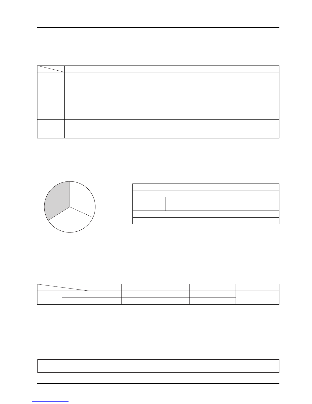
The Lossnay recuperates approximately 70% of the outdoor air load and saves on approximately 30% of the total load.
Outdoor
air load 41.9%
56.0 W/m
2
(48.0 kcal/h·m2)
Indoor heat
loss 58.1%
77.7 W/m
2
(67.0 kcal/h·m2)
133.7 W/m
2
(115.0 kcal/h·m2)


CHAPTER 2
Lossnay Construction and Principle
16
CHAPTER 2 ● Lossnay Construction and Principle
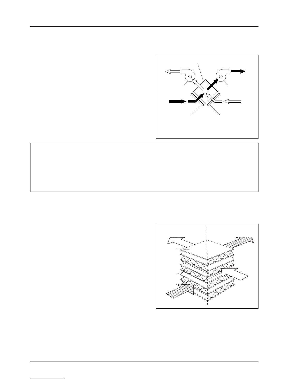
1. Construction and Features of Lossnay
● Lossnay construction
The Lossnay is constructed so that the exhaust air passage from
the indoor side to the outdoor side (RA → EA) and the fresh air
passage from the outdoor side to the indoor side (OA → SA)
cross. The Lossnay heat recovery unit (Lossnay Core) is installed
at this cross point, and recovers the heat by conduction through
the separating medium between these airflows. This enables the
heat loss during exhaust to be greatly reduced.
* RA : Return Air
EA : Exhaust Air
OA : Outdoor Air
SA : Supply Air
SA
(Supply air diffuser)
Supply fan
RA
(Return air)
Exhaust side filter
Lossnay Core
Intake side filter
OA
(Outdoor air)
Exhaust fan
EA
(Exhaust air)
Main Features of Lossnay
(1) Cooling and heating maintenance fees are saved while ventilating.
(2) The capacity and performance of the air conditioner can be reduced.
(3) Dehumidifying during summer, and humidifying during winter is possible.
(4) Comfortable ventilation is possible, (the outdoor air being adjusted to the room temperature.)
(5) Effective sound-proofing.
Note: The dust inlet and outlet are linear in the
actual product.
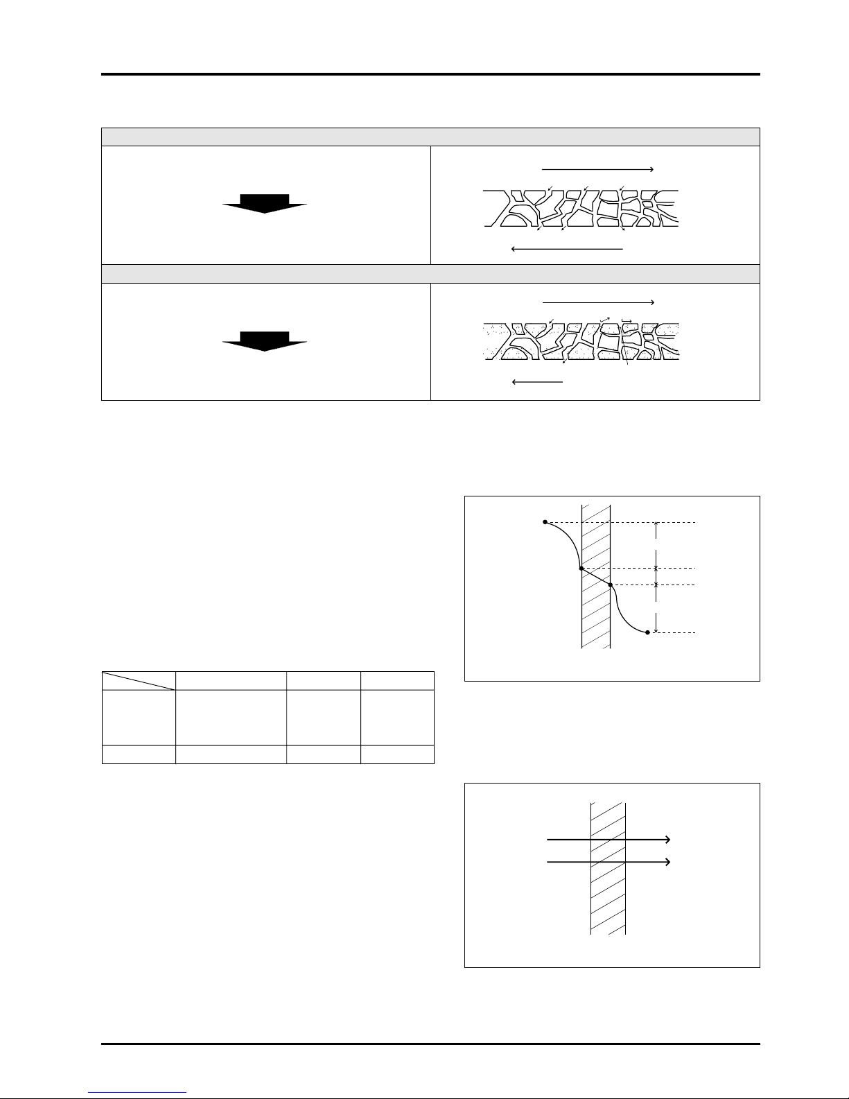
2. Construction and Principle of Core
● Simple construction
The Lossnay Core is a cross-flow total heat recovery unit
constructed of plates and fins made of treated paper.
The fresh air and exhaust air passages are totally separated
allowing the fresh air to be introduced without mixing with the
exhaust air.
●
Principle
The Lossnay Core uses the heat transfer properties and moisture
permeability of the treated paper. Total heat (sensible heat plus
latent heat) is transferred from the stale exhaust air to the fresh air
being introduced into the system when they pass through the
Lossnay. Try this simple experiment. Roll a piece of paper into a
tube and blow through it. Your hand holding the paper will
immediately feel warm. If cold air is blown through the tube, your
hand will immediately feel cool. Lossnay is a total heat exchanger
that utilizes these special properties of paper.
●
Treated paper
The paper partition plates are treated with special chemicals so that the Lossnay Core is an appropriate heat recovery unit for
the ventilator. This paper differs from ordinary paper, and has the following unique properties.
(1) The paper is incombustible and is strong.
(2) The paper has selective hydroscopicity and moisture permeability that permits the passage of water vapor only (including
some water-soluble gases).
(3) The paper has gas barrier properties that does not pass gases such as CO
2.
SA
Supply air diffuser
(Fresh cold or warm air)
Partition
plate
(Treated
paper)
Spacer plate
(Treated paper)
RA
Return air
(Stale cold or warm air)
Indoors Outdoors
EA
Exhaust air
(Stale air)
OA
Outdoor air
(Fresh air)
17
CHAPTER 2 ● Lossnay Construction and Principle
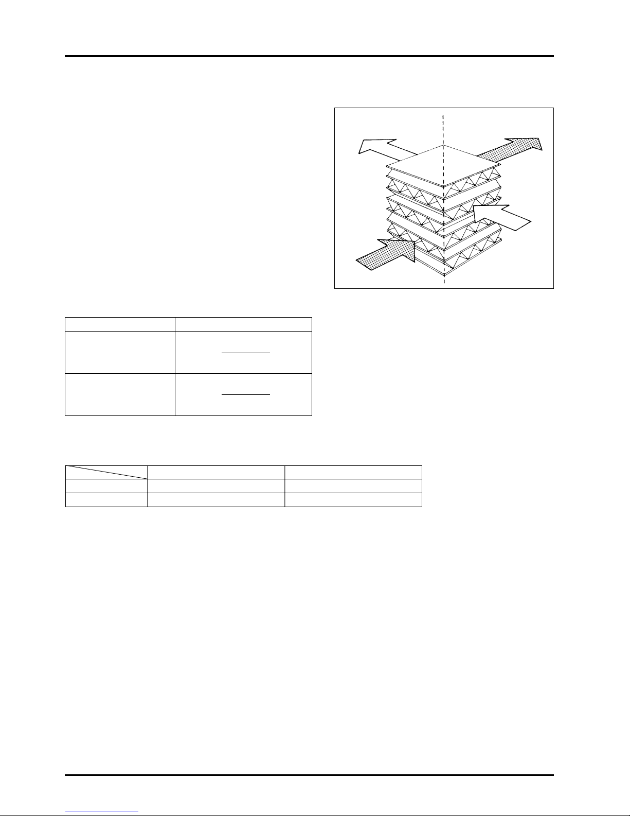
A comparison of the ordinary paper and the Lossnay Core plates is as shown in the table.
Ordinary paper
Water vapor is transferred, but gas elements that are easily
dissolved in water such as CO
2, NO2 are also transferred.
The contaminated air passes through the plates during
ventilation and returns to the room.
Treated paper
Water vapor is transferred, but gas elements such as CO
2,
NO
2 are not transferred.
The contaminated air does not return to the room when
ventilated.
Highly humid air
Water vapor
Water vapor
CO2 NO2
CO2 NO2
CO2 NO2Water vapor
Water vapor
Treatment
(Selective permeable film)
(Incombustible specifications)
Low humid air
Highly humid air
Cellulose
fibers
Low humid air
● Total heat recovery mechanism
Sensible heat and latent heat
The heat that enters and leaves in accordance with changing temperature (rise or drop) is called sensible heat. The heat that
enters and leaves due to the changes in a matter’s physical properties (evaporation, condensation) is called latent heat.
(1) Temperature (sensible heat) recovery
1) Heat conduction and heat passage is performed through a
partition plate from the high temperature to low temperature
side.
2) As shown on the right, the heat recovery efficiency is affected
by the resistance of the boundary layer, and for the Lossnay
there is little difference when compared to materials such as
copper or aluminium which also have high thermal
conductivity.
Heat resistance coefficients
t1
t2
Ra1
Ra2
Rp
Partition plate
Ra1+Ra2
»Rp
Treated paper Cu Al
Ra
1 10 10 10
Rp 1 0.00036 0.0006
Ra
2 10 10 10
Total 21 20.00036 20.0006
(2) Humidity (latent heat) recovery
●
Water vapor is moved through the partition plate from the
high humidity to low humidity side by means of the
differential pressure in the vapor.
High humidity side
Low humidity side
Partition plate
18
CHAPTER 2 ● Lossnay Construction and Principle
3. Calculation of the Total Heat Recovery Efficiency
The Lossnay Core’s heat recovery efficiency can be considered
using the following three transfer rates:
(1) Temperature (sensible heat) recovery efficiency
(2) Humidity (latent heat) recovery efficiency
(3) Enthalpy (total heat) recovery efficiency
The heat recovery effect can be calculated if two of the above
efficiencies is known. (The temperature and enthalpy efficiencies
are indicated in the applicable catalogue.)
●
Each recovery efficiency can be calculated with the formulas
given below.
●
When the supply air volume and exhaust air volume are equal,
the heat recovery efficiencies on the supply and exhaust sides
are the same.
●
When the supply air volume and exhaust air volume are not
equal, the total heat recovery efficiency is low if the exhaust
volume is lower, and high if the exhaust volume is higher.
Refer to the Heat Recovery Efficiency Correction Curve in the
applicable catalogue for more details.
SA
Supply air
(Fresh cold or warm air)
RA
Return air
(Stale cold or warm air)
Indoors Outdoors
EA
Exhaust air
(Stale air)
OA
Outdoor air
(Fresh air)
Item Formula
Temperature recovery
efficiency (%)
ηt =
t (
OA) - t (SA)
× 100
t (
OA) - t (RA)
Enthalpy recovery
efficiency (%)
ηi =
i (
OA) - i (SA
)
× 100
i (
OA) - i (
RA)
η: Efficiency (%)
t : Dry bulb temperature (°C)
i : Enthalpy (kJ/kg) (kcal/kg’)
Calculation of air conditions after passing through Lossnay
If the Lossnay heat recovery efficiency and the conditions of the room and outdoor air are known, the conditions of the air
entering the room and the air exhausted outdoors can be determined with the following formulas.
Supply side Exhaust side
Temperature t
SA = tOA - (tOA - tRA) · ηttEA = tRA + (tOA - tRA) · ηt
Enthalpy i
SA = iOA - (iOA - iRA) · ηiiEA = iRA + (iOA - iRA) · ηi
19
CHAPTER 2 ● Lossnay Construction and Principle
4. What is a Psychrometric Chart?
The chart which shows the properties of humid air is called a psychrometric chart. The psychrometric chart can be used to
find the (1) Dry bulb temperature, (2) Wet bulb temperature, (3) Absolute humidity, (4) Relative humidity, (5) Dew point and (6)
Enthalpy (total heat) of a certain air condition. If two of these values are known beforehand, the other values can be found with
this chart. The way that the air will change when it is heated, cooled, humidified or dehumidified can also be seen easily on
the chart.
(1) Dry bulb temperature t (°C)
Generally referred to as standard temperature this is
measured with a dry bulb thermometer (conventional
thermometer). The obtained value is the dry bulb
temperature.
(2) Wet bulb temperature t’ (°C)
When a dry bulb thermometer’s heat sensing section is
wrapped in a piece of wet gauze and an ample air flow
(3 m/s or more) is applied, the heat applied to the wet bulb by
the air and the heat of the water vapor that evaporates from
the wet bulb will balance at an equal state. The temperature
indicated at this time is called the wet bulb temperature.
(3) Absolute humidity x (kg/kg’)
The weight (kg) of the water vapor that corresponds to the
weight (kg’) of the dry air in the humid air is called the
absolute humidity.
(4) Relative humidity ϕ (%)
The ratio of the water vapor pressure Pw in the humid air and
the water vapor pressure Pws in the saturated air at the same
temperature is called the relative humidity. This is obtained
with the following formula:
ϕR = PW/PWS × 100
(5) Dew point t” (°C)
The water content in the air will start to condense when air is
cooled.
The dry bulb temperature at this time is called the dew point.
(6) Enthalpy i (kJ/kg) (kcal/kg’)
Physical matter has a set heat when it is at a certain
temperature and state. This retained heat is called the
enthalpy, with dry air at 0 °C being set at 0.
Temperature (°C)
Absolute humidity x (kg/kg’)
Wet bulb temperature
(dew point) t’ (°C)
Relative humidity ϕ (%)
The dew point t” of the air at point A is the
temperature of the point at the same absolute humidity
as point A on the saturation curve.
t” °C dew point
(kJ/kg)
Enthalpy i (kcal/kg’)
A
t”
Parallel to absolute
temperature scale line
20
CHAPTER 2 ● Lossnay Construction and Principle
5. Calculation of Lossnay Heat Recovery
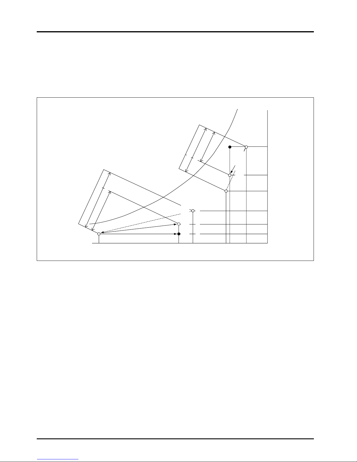
The following figure shows the conditions of various air states when fresh air is introduced through the Lossnay Core. If a
conventional sensible heat recovery unit is used alone and is assumed to have the same heat recovery efficiency as Lossnay,
the condition of the air supplied to the room is expressed by point A in the figure. This point shows that the air is very humid in
summer and very dry in winter.
The air supplied to the room with Lossnay is indicated by point S in the figure. The air is precooled and dehumidified in the
summer and preheated and humidified in the winter before it is introduced to the room.
iSA
iOA
tOA tSA
A
S
O
R
i
RA
iSA
iOA
tRA tRA
S
R
AO
t
SA tOA
XOA
XSA
XRA
XRA
XSA
XOA
iRA
The quantity of heat recovered by using the Lossnay Core can be calculated with the following formula.
Total heat recovered: q
T = γ · Q · (iOA - iSA) [W (kcal/h)]
= γ · Q · (i
OA
- i
RA) ×ηi
Where γ = Specific weight of air under standard conditions 1.2 (kg/m
3
)
Q = Treated air volume (m
3
/h)
t = Temperature (°C)
x = Absolute humidity (kg/kg’)
i = Enthalpy (kJ/kg) (kcal/kg’)
η = Heat recovery efficiency (%)
●
Suffix meanings
OA : Outdoor air
RA : Return air
SA : Supply air
Enthalpy
(kJ/kg) (kcal/kg
’)
Outdoor air load
Lossnay Core heat recovery
Enthalpy
(kJ/kg) (kcal/kg
’)
Outdoor air load
Lossnay Core heat recovery
Outdoor air
condition in
winter
Supply air condition of
the Lossnay
Supply air condition of
the Lossnay
Room air
condition
in summer
Outdoor air condition
in summer
Absolute
humidity (kg/kg’)
Room air condition in winter
Dry bulb temperature (°C)

CHAPTER 3
General Technical Considerations
1. Lossnay Heat Recovery Effect
1.1 Comparison of outdoor air load of various ventilators
Examples of formulas to compare the heat recovered and outdoor air load when ventilating with the Lossnay (total heat
recovery unit), sensible heat recovery ventilation (sensible HRV) and conventional ventilators are shown below.
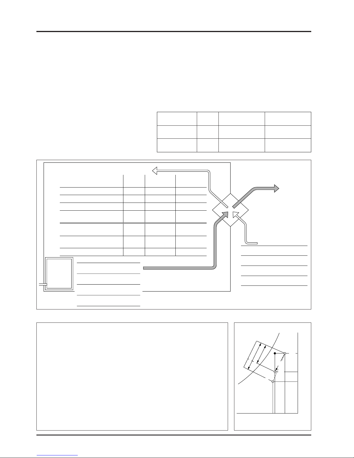
(1) Cooling during summer
Conditions
●
Model LGH-50R type
●
Heat recovery efficiency table (%)
(at 50Hz, high speed) (For summer)
●
Ventilation rate: 500 m3/h
(specific gravity of air
ρ
= 1.2 kg/m3)
22
CHAPTER 3 ● General Technical Considerations
Lossnay Sensible HRV
Conventional
ventilator
Temperature
77 77 –
(sensible heat)
Enthalpy
61.5 18.2* –
(total heat)
hOA
hSA
hRA
85.0
65.4
53.2
tOA
33
tSA
27.6
tRA
26
R
S
AO
X
OA
0.0203
XSA
0.0148
XRA
0.0105
●
Lossnay
(Supply air diffuser temperature)
tSA = 33°C – (33°C – 26°C) × 0.77 = 27.6°C
(Supply air diffuser enthalpy)
hSA = 85.0 – (85.0 – 53.2) × 0.615 = 65.4 kJ/kg
Heat recovered
(85.0 – 65.4) × 1.2 × 500 = 11,760 kJ/h = 3.3 kW (2,809 kcal/h)
Outdoor air load
(65.4 – 53.2) × 1.2 × 500 = 7,320 kJ/h = 2.0 kW (1,749 kcal/h)
●
Sensible HRV
(Supply air diffuser temperature)
tSA = 33°C – (33°C – 26°C) × 0.77 = 27.6°C
(Supply air diffuser enthalpy)
hSA
= 79.2 kJ/kg (18.9 kcal/kg) (from psychrometric chart)
Heat recovered
(85.0 – 79.2) × 1.2 × 500 = 3,480 kJ/kg = 1.0kW (831 kcal/h)
Outdoor air load
(79.2 – 53.2) × 1.2 × 500 = 15,600 kJ/H = 4.3 kW (3,727 kcal/h)
[Calculated enthulpy recovery efficiency 3,480 ÷ (3,480 + 15,600) × 100 = 18.2]
●
Conventional ventilator
If a conventional ventilator is used, the heat recovered will be 0 as the supply air
diffuser is equal to the outdoor air.
The outdoor air load is:
(85.0 – 53.2)
×
1.2 ×500 = 19,080 kJ/h = 5.3 kW (4558 kcal/h)
Calculation example Summer conditions
Absolute humidity (kg/kg’)
Room air condition in summer
Outdoor air condition
in summer
Supply air condition
of the Lossnay
Dry bulb temperature (°C)
L
o
s
sn
a
y h
e
a
t re
c
o
ve
ry
Outdoor air load
Enthalpy
kJ/kg
Supply air
Room air
Air
conditioner
Lossnay Sensible HRV
Conventional
ventilator
Dry bulb
temperature
Absolute
humidity
Relative
humidity
Enthalpy
26°C
27.6 27.6 33
14.8 20.3 20.3
63 86 63
65.4 79.2 85.0
(15.6) (18.9) (20.3)
3.3 1.0
0
(2,809) (831)
2.0 4.3 5.3
(1,749) (3,727) (4,558)
38.5 82 100
10.5 g/kg’
50%
53.2 kJ/kg
(12.7 kcal/kg’)
Outdoor air
Exhaust air
Dry bulb
temperature
Absolute
humidity
Relative
humidity
Enthalpy
33°C
20.3 g/kg’
63%
85.0 kJ/kg
(20.3 kcal/kg’)
Dry bulb temperature (°C)
Absolute humidity (g/kg’)
Relative humidity (%)
Enthalpy
(kJ/kg)
(kcal/kg’)
Outdoor air load
(kW)
(kcal/h)
Outdoor air load ratio (%)
Total heat recovered
(kW)
(kcal/h)
* Calculated volume under below conditions.
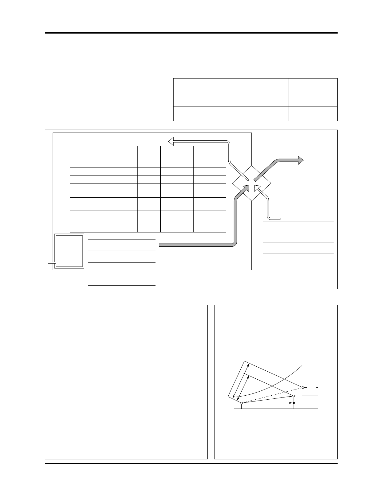
(2) Heating during winter
Conditions:
●
Model LGH-50R type
●
Heat recovery efficiency table (%)
(at 50Hz, high speed) (For winter)
●
Ventilation rate: 500 m3/h
(Specific gravity of air
ρ
= 1.2 kg/m3)
23
CHAPTER 3 ● General Technical Considerations
Lossnay Sensible HRV
Conventional
ventilator
Temperature
77 77 –
(sensible heat)
Enthalpy
67 44.2* –
(total heat)
Supply air
Room air
Air
conditioner
Lossnay Sensible HRV
Conventional
ventilator
Dry bulb
temperature
Absolute
humidity
Relative
humidity
Enthalpy
20°C
15.4 15.4 0
4.6 1.8 1.8
43 17 50
27.4 19.8 5.0
(6.5) (4.7) (1.2)
3.7 2.4
0
(3,211) (2,121)
1.9 3.2 5.6
(1,591) (2,680) (4,802)
33 57 100
7.2 g/kg’
50%
38.5 kJ/kg
(9.2 kcal/kg’)
Outdoor air
Exhaust air
Dry bulb
temperature
Absolute
humidity
Relative
humidity
Enthalpy
0°C
1.8 g/kg’
50%
5.0 kJ/kg
(1.2 kcal/kg’)
Dry bulb temperature (°C)
Absolute humidity (g/kg’)
Relative humidity (%)
Enthalpy
(kJ/kg)
(kcal/kg’)
Outdoor air load
(kW)
(kcal/h)
Outdoor air load ratio (%)
Total heat recovered
(kW)
(kcal/h)
●
Lossnay
(Supply air diffuser temperature) tSA=
(20°C – 0°C) × 0.77 + 0°C = 15.4°C
(Supply air diffuser
enthalpy)
hSA=
(38.5 – 5.0) × 0.67 + 5.0
=
27.4 kJ/kg
Heat recovered (27.4 – 5.0) × 1.2 × 500
= 13,440 kJ/h = 3.7 kW (3,211 kcal/h)
Outdoor air load (38.5 – 27.4) × 1.2 × 500
=
6,660 kJ/h = 1.9 kW (1,591 kcal/h)
●
Sensible HRV
(Supply air diffuser temperature) tSA=
(20°C – 0°C) × 0.77 + 0°C = 15.4°C
(Supply air diffuser
enthalpy)
hSA=
19.8 kJ/kg (4.7 kcal/kg’)
(from psychrometric chart)
Heat recovered (19.8 – 5.0) × 1.2 × 500
= 8,880 kJ/h = 2.5 kW (2,121kcal/h)
Outdoor air load (38.5 – 19.8) × 1.2 × 500
= 11,200 kJ/h = 3.1 kW (2,681 kcal/h)
[Calculated enthulpy recovery efficiency 8,880 ÷ (8,880 + 11,200) × 100 = 44.2]
●
Conventional ventilator
If a conventional ventilator is used, the supply air diffuser is the same
as the outdoor air and the exhaust is the same as the room air.
Thus the heat recovered is 0 kcal and the outdoor air load is
(38.5 – 5.0) × 1.2 × 500 = 20,100 kJ/h = 5.6 kW (4,802 kcal/h)
Calculation example Winter conditions
hRA
iOA
tOA
0
tSA
15.4
tRA
20
R
S
O
A
X
RA 0.0072
XSA 0.0046
XOA 0.0018
hSA
38.5
5.6
27.4
Absolute humidity (kg/kg’)
Outdoor air
condition in
winter
Room air condition
in winter
Supply air condition
of the Lossnay
Dry bulb temperature (°C)
Lossnay
heat recovery
Outdoor air load
Enthalpy
kJ/kg
* Calculated volume under below conditions.
24
CHAPTER 3 ● General Technical Considerations
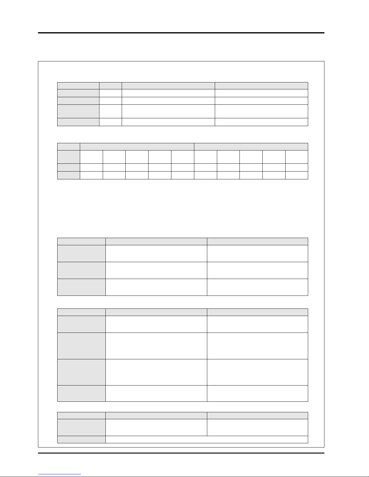
2. Example Heat Recovery Calculation
(1) Setting of conditions
(Note: Tokyo Power, industrial power 6 kV supply)
●
Return air volume (RA) = 7,200 m3/Hr
●
Outdoor air volume (OA) = 8,000 m3/Hr
●
Air volume ratio (RA/OA) = 0.9
●
Air conditions
(2) Selection of Lossnay model (select from treatment air volume catalogue)
●
Model name: LU-160 with combination of LU-1605 × 1 unit
●
Processing air volume per unit RA = 7,200 m3/Hr, OA = 8,000 m3Air volume ratio (RA/OA) = 0.9
●
Heat recovery efficiency : Heat recovery efficiency = 73%, Enthalpy recovery efficiency (cooling) = 62%,
Enthalpy recovery efficiency (heating) = 67%
●
S
tatic pressure loss (unit-type) RA = 156.9 Pa, OA = 186.3 Pa (Note: Each with filters)
●
Power consumption (pack-type) = none because of unit type
(3) State of indoor supply air
(4) Outdoor air load and heat recovered
(5) Recovered money (power rates)
Units When Heating When Cooling
Operation time (h/yr)
10h/day × 26 days/mo. × 5 mo./yr. = 1,300 h/yr 10h/day × 26 days/mo. × 4 mo./yr. = 1,040 h/yr
Electricity fee
(yen/kWh)
16.22 17.84
Capacity per
(kW/kW) 3.1 2.6
1 kW of electricity
Energy unit cost
(yen/kWh)
16.22/3.1 = 5.23 17.84/2.6 = 6.86
Season Winter heating Summer cooling
Item
Dry bulb temp. Wet bulb temp.
Relative humidity Absolute humidity
Enthalpy h Dry bulb temp. Wet bulb temp.
Relative humidity Absolute humidity
Enthalpy h
DB [°C] WB [°C] RH [%] × [kg/kg (DA)] [kJ/kg (DA)] DB [°C] WB [°C] RH [%] × [kg/kg (DA)] [kJ/kg (DA)]
Outdoors 0 –2.7 50 0.0018 5.0 (1.2) 33 27.1 63 0.0202
85.0 (20.3)
Indoors 20 13.8 50 0.0072 38.5 (9.2) 26 18.7 50 0.0105
53.0 (12.7)
Heating Cooling
= { 20 (Indoor temperature) – 0 (outdoor air temperature)} × = 33
(Outdoor air temperature) – { 33 (outdoor air temperature) –
Temperature [°C] 0.73 (heat recovery efficiency) + 0 (outdoor air temperature) 26 (indoor temperature)} × 0.73 (heat recovery efficiency)
= 14.6 = 27.89
Enthalpy
= {38.5 (Indoor enthalpy) – 5.0 (outdoor air enthalpy)} × = 85 (Outdoor air enthalpy) – { 85 (outdoor air enthalpy) –
[kJ/kg (DA)]
0.67 (enthalpy recovery efficiency) + 5.0(outdoor air enthalpy)
53.2
(indoor enthalpy)} × 0.62 (enthalpy recovery efficiency)
= 27.4 = 65.3
Numerical value obtained •Dry-bulb temperature = 14.6 °C •Wet-bulb temperature = 9.2 °C•Dry-bulb temperature = 27.89 °C •Wet-bulb temperature = 22.4 °C
from above equation and •Relative humidity = 49% •Absolute humidity = 0.005 kg/kg (DA)•Relative humidity = 62% •Absolute humidity = 0.0146 kg/kg (DA)
psychometric chart
•
Enthalpy = 27.4 kJ/kg (DA)
•
Enthalpy = 65.3 kJ/kg (DA)
Heating Cooling
Fresh air load without
= 1.2 (Air specific gravity) × 8,000 (outdoor air volume) × = 1.2 (Air specific gravity) × 8,000 (outdoor air volume) ×
Lossnay (q
1)
{ 38.5 (indoor enthalpy) – 5.0 (outdoor air enthalpy) } { 85.0 (outdoor air enthalpy) – 53.2 (indoor enthalpy) }
= 321,600 kJ/h = 89.3 kW = 305,280 kJ/h = 84.8 kW
= 89.3 (Outdoor air load) (q
1) × = 84.8 (Outdoor air load) (q1) ×
Outdoor air load with
{ 1 – 0.67 (enthalpy recovery efficiency)} { 1 – 0.62 (enthalpy recovery efficiency) }
Lossnay (q
2)
= 29.5kW = 32.2 kW
or or
=
Air specific gravity × outdoor air volume × (indoor enthalpy – indoor blow enthalpy)= Air specific gravity × outdoor air volume × (indoor enthalpy – indoor blow enthalpy)
= q
1
– q2 = q1 – q2
= 89.3 – 29.5 = 84.8 – 32.2
Heat recovered (q
3)
= 59.8 = 56.2 kW
or or
= Outdoor air load (q1) × enthalpy recovery efficiency = Outdoor air load (q1) × enthalpy recovery efficiency
•
Outdoor air load = 89.3 kW = 100%
•
Outdoor air load =84.8 kW = 100%
(%) outdoor air load•Outdoor air load with Lossnay = 29.5 kW = 33%
•
Outdoor air load with Lossnay = 32.2 kW = 38%
•
Heat recovered = 59.8 kW = 67%
•
Heat recovered = 52.6 kW = 62%
Heating Cooling
=
Heat recovered: kW ×Unit price yen/W ×operation time Hr/year = Heat recovered: kW × Unit price yen/W × operation time Hr/year
Yearly saved money = 59.8 kW × 5.232 yen/kWh × (1,300hr/year) = 52.6 kW × 6.86 yen × (1,040hr/year)
= 406,580 yen = 375,269 yen
Remarks If recovered heat is converted to electricity : heating = 59.8 kW/3.1 = 19.3 kW/h cooling = 52.6 kW/2.6 = 20.2 kW/h
Caution: See the psychrometric chart on the next page.

25
CHAPTER 3 ● General Technical Considerations
●
Psychrometric chart for calculating Lossnay economical effect
The following can be determined from the above calculation results:
●
Saving of 59.8 kW of the heating load, and 52.6 kW of the cooling load is possible.
The heat source equipment and related ventilator capacity that is equivalent to this saved amount can be reduced, thus the
operation and maintenance costs can also be saved.
●
Approximately 400,000 yen can be saved in operation and maintenance costs during heating and 370,000 yen during
cooling, for a total savings of approximately 770,000 yen. Furthermore, as 20.2 kW can be saved from the basic power rates
during cooling, approximately 370,000 yen (20.2 × 1,560 yen/month × 12 months) can be saved annually.
27.4
38.5
53.2
65.3
85.0
5.0
0 14.6 20 26 33
0.0018
0.005
0.0072
0.0105
0.0146
0.0203
27.89
0.00.000
0.001
0.002
0.003
0.004
0.005
0.006
0.007
0.008
0.009
0.010
0.011
0.012
0.013
0.014
0.015
0.016
0.017
0.018
0.019
0.020
0.021
0.022
0.023
0.024
0.025
0.026
0.027
0.028
0.029
0.030
0.031
0.032
0.033
0.034
0.035
0.036
0.037
0.1
0.5
1.0
1.5
2.0
2.5
3.0
3.5
4.0
4.5
5.0
5.5
T.FUJITA
1987
VaporpressurePw[kPa]
Absolutehumidity x [kg/kg(DA)]
50494847464544434240 41393837363534333230 31292827262524232220 21191817161514131210 11987654320–1–2–3–4–9–10
0.75 0.76 0.77 0.78 0.79 0.80 0.81 0.82 0.83 0.84 0.85 0.86 0.87 0.88 0.89 0.90 0.91
–7–8 –5–6 1
1
8
1
9
2
0
5
5
6
0
6
5
7
0
2
2
2
1
2
3
2
4
2
5
7
5
8
0
2
6
2
7
8
5
9
0
2
8
2
9
9
5
1
0
0
1
0
5
1
1
0
3
1
1
1
5
1
2
0
3
3
3
2
3
4
3
5
1
2
5
3
0
5
0
4
5
4
0
3
5
1
1
1
0
9
8
7
6
4
5
3
2
1
0
–
1
–
2
–
4
–
5
–5
0
5
10
90
80
70
60
50
40
30
25
6
0
5
5
6
5
7
0
7
5
8
0
8
5
9
5
9
0
8
5
8
0
7
5
7
0
6
5
60
5
5
ψ
5
0
ψ
50
45
4
0
4
0
4
5
3
5
3
0
25
20
15
10
5
35
30
2
5
20
15
20
10
5
15
15
25
30
2
0
–
8
1
0
5
0
1
5
2
0
2
5
3
0
1
2
1
3
1
4
1
5
1
6
1
7
±
∞
–
400
00
40000
20000
15000
10000
7
00
0
6
0
0
0
50
00
4500
4
2
0
0
4
0
0
0
3800
–20000
–10000
–
5000
–2000
–
1
0
0
0
–500
0
500
1000
1200
1400
1
60
0
1800
2000
2200
2400
2600
2
8
0
0
3000
3200
3
4
0
0
3600
3
8
0
0
1.0
0
.9
0.8
0.7
0
.6
0.5
0.4
0
.3
Comparativeenthalpy
h[kJ/kg(DA)]
Humid air psychrometric chart
(-10 to +50°C, atmospheric pressure 101.325 kPa)
H
eatw
aterra
tio
u = ––
[kJ/kg]
dh
dx
Sensibleheatratio
SFH
S
a
tu
ra
tio
n
[%
]
0.94
0.92
0.93
0.96
0.95
Wetbulbtemperaturet'[°C]
Drybulbtemperaturet[°C]
Relativehum
idity
[%
]
C
h
ille
d
Water
Specificcapacityv [m
3
/kg(DA)]
26
CHAPTER 3 ● General Technical Considerations
3. Calculation of Lossnay Economical Effects
The following is a sample questionnaire from which it is possible to assess the economical benefits of using the Lossnay in
particular applications.
(1) Setting of conditions
●
Return air volume (RA) = m3/Hr
●
Outdoor air volume (OA) = m3/Hr
●
Air volume ratio (RA/OA) =
●
Air conditions
●
Operation time: Heating = hours/day × days/month × months/year = hours/year
Cooling = hours/day × days/month × months/year = hours/year
●
Energy: Heating = Type: Electricity Cost: ¥ /kWh
Cooling = Type: Electricity Cost: ¥ /kWh
Power rates: Winter: ¥/kWh Summer: ¥ /kWh
(2) Selection of Lossnay model (select from treatment air volume catalog)
●
Model name:
●
Processing air volume per unit RA = m3/Hr, OA = m3, Air volume ratio (RA/OA) =
●
Heat recovery efficiency :
Heat recovery efficiency = %,
Enthalpy recovery efficiency (cooling) = %,
Enthalpy recovery efficiency (heating) = %
●
Static pressure loss (unit-type) RA= mm H
2O OA = mm H
2O (Note: Each with filters)
●
Power consumption (pack-type) = none because of unit type
(3) State of indoor blow air
Season Winter heating Summer cooling
Dry bulb Wet bulb Relative Absolute Enthalpy Dry bulb Wet bulb Relative Absolute Enthalpy
Item temp. temp. humidity humidity i kJ/kg temp. temp. humidity humidity i kJ/kg
DB [°C] WB [°C] RH [%] × [kg/kg’] (kcal/kg’) DB [°C] WB [°C] RH [%] × [kg/kg’] (kcal/kg’)
Outdoors
Indoors
Heating Cooling
= (Indoor temperature – outdoor air temperature) × = Outdoor air temperature – (outdoor air
Temperature [°C]
heat recovery efficiency + outdoor air temperature – indoor temperature) ×
temperature heat recovery efficiency
==
= (Indoor enthalpy – outdoor air enthalpy) × = Outdoor air enthalpy – (outdoor air
Enthalpy enthalpy recovery efficiency + outdoor air enthalpy – indoor enthalpy) ×
[kJ/kg(kcal/kg)] enthalpy enthalpy recovery efficiency
==
Numerical value
●
Dry-bulb temperature = °C
●
Dry-bulb temperature = °C
obtained from above
●
Wet-bulb temperature = °C
●
Wet-bulb temperature = °C
equation and
●
Relative humidity = %
●
Relative humidity = %
psychometric chart
●
Absolute humidity = kg/kg’
●
Absolute humidity = kg/kg’
●
Enthalpy = kg/kg
(kcal/kg)●Enthalpy = kg/kg
(kcal/kg)

27
CHAPTER 3 ● General Technical Considerations
(4) Outdoor air load and heat recovery
Heating Cooling
Fresh air load without
= Air specific gravity × outdoor air volume = Air specific gravity × outdoor air volume
Lossnay (q
1)
× (indoor enthalpy
–
outdoor air enthalpy) × (outdoor air enthalpy – indoor enthalpy)
==
= Outdoor air load (q
1) = Outdoor air load (q1)
× ( 1 – enthalpy recovery efficiency) × ( 1 – enthalpy recovery efficiency)
Outdoor air load with = =
Lossnay (q
2
)or or
= Air specific gravity × outdoor air volume = Air specific gravity × fresh air volume
× (indoor enthalpy
–
indoor blow enthalpy) × (indoor blow enthalpy – indoor enthalpy)
=q
1
–
q2 =q1
–
q2
=
–
=
–
Heat recovery (q3)
==
or or
= Outdoor air load (q
1) = Outdoor air load (q1)
× enthalpy recovery efficiency × enthalpy recovery efficiency
● Outdoor air load = W = % ● Outdoor air load = W = %
(%) to outdoor air
● Outdoor air load with Lossnay ● Outdoor air load with Lossnay
load = W = % = W = %
● Heat recovered = W = % ● Heat recovered = W = %
(5) Recovered money (power rates)
Heating Cooling
=
Heat recovered: kW × Unit price ¥/kWh ×
=
Heat recovered: kW × Unit price ¥/kWh ×
Yearly saved money
operation
time Hr/year = kW ×¥/
kWh
×
operation
time Hr/year = kW ×¥/
kWh
×
¥
= Hr/year = Hr/year
==
 Loading...