


 Loading...
16-1
ENGINE
ELECTRICAL
CONTENTS
CHARGING SYSTEM . . . . . . . . . . . . . . . . |
2 IGNITION SYSTEM . . . . . . . . . . . . . . . . . |
26 |
GENERAL INFORMATION . . . . . . . . . . . . . . . . 2 SERVICE SPECIFICATIONS . . . . . . . . . . . . . . . 3 SPECIAL TOOL . . . . . . . . . . . . . . . . . . . . . . . . . . 3 ON-VEHICLE SERVICE . . . . . . . . . . . . . . . . . . . 4
Alternator Output Line Voltage Drop Test . . . . . . 4 Output Current Test . . . . . . . . . . . . . . . . . . . . . . . . 5 Regulated Voltage Test . . . . . . . . . . . . . . . . . . . . . 7 Waveform Check Using An Analyzer . . . . . . . . . . 8
ALTERNATOR . . . . . . . . . . . . . . . . . . . . . . . . . . 10
STARTING SYSTEM . . . . . . . . . . . . . . . . 17
GENERAL INFORMATION . . . . . . . . . . . . . . . 17 SERVICE SPECIFICATIONS . . . . . . . . . . . . . . 17 ON-VEHICLE SERVICE . . . . . . . . . . . . . . . . . . 18 STARTER . . . . . . . . . . . . . . . . . . . . . . . . . . . . . . 18
GENERAL INFORMATION . . . . . . . . . . . . . . . 26
SERVICE SPECIFICATIONS . . . . . . . . . . . . . . 27
SPECIAL TOOL . . . . . . . . . . . . . . . . . . . . . . . . . 27
ON-VEHICLE SERVICE . . . . . . . . . . . . . . . . . . 28
Ignition Coil (With Built-in Power Transistor)
Check . . . . . . . . . . . . . . . . . . . . . . . . . . . . . . . . . . . 28
Resistive Cord Check . . . . . . . . . . . . . . . . . . . . . 28
Spark Plug Check, Cleaning and Replacement 29
Camshaft Position Sensor Check . . . . . . . . . . . 29
Crank Angle Sensor Check . . . . . . . . . . . . . . . . 29
Detonation Sensor Check . . . . . . . . . . . . . . . . . . 29
Waveform Check Using An Analyzer . . . . . . . . 30
IGNITION COIL . . . . . . . . . . . . . . . . . . . . . . . . . 34 CAMSHAFT POSITION SENSOR . . . . . . . . . 35 CRANK ANGLE SENSOR . . . . . . . . . . . . . . . . 35 DETONATION SENSOR . . . . . . . . . . . . . . . . . 37

16-2 |
ENGINE ELECTRICAL - Charging System |
|
|
CHARGING SYSTEM
GENERAL INFORMATION
The charging system uses the alternator output to keep the battery charged at a constant level under various electrical loads.
Voltage
Approximately
14.4 V
OPERATION
Rotation of the excited field coil generates AC voltage in the stator.
This alternating current is rectified through diodes to DC voltage having a waveform shown in the illustration at left. The average output voltage fluctuates slightly with the alternator load condition.
Time
When the ignition switch is turned on, current flows in the field coil and initial excitation of the field coil occurs.
When the stator coil begins to generate power after the engine is started, the field coil is excited by the output current of the stator coil.
The alternator output voltage rises as the field current increases and it falls as the field current decreases. When the battery voltage (alternator S terminal voltage) reaches a regulated voltage
of approximately 14.4 V, the field current is cut off. When the battery voltage drops below the regulated voltage, the voltage regulator regulates the output voltage to a constant level by controlling the field current.
In addition, when the field current is constant, the alternator output voltage rises as the engine speed increases.
SYSTEM DIAGRAM
|
B |
|
|
Stator coil |
|
|
|
|
Engine-ECU |
|
|
Field coil |
G |
|
|
|
S |
|
|
Voltage |
L |
|
|
FR |
|
|
|
regulator |
Ignition |
Battery |
|
|
Charging |
switch |
|
|
warning lamp |
|
|

|
ENGINE ELECTRICAL - Charging System |
16-3 |
|||||||
|
|
|
|
|
|
|
|
|
|
ALTERNATOR SPECIFICATIONS |
|
|
|
|
|
|
|||
|
|
|
|
|
|
|
|
|
|
Items |
|
|
|
Specifications |
|
|
|
||
|
|
|
|
|
|
|
|
|
|
Type |
|
|
|
Battery voltage sensing |
|
||||
|
|
|
|
|
|
|
|
|
|
Rated output V/A |
|
|
|
12/90 |
|
|
|
|
|
|
|
|
|
|
|
|
|
|
|
Voltage regulator |
|
|
|
Electronic built-in type |
|
||||
|
|
|
|
|
|
|
|
|
|
SERVICE SPECIFICATIONS |
|
|
|
|
|
|
|||
|
|
|
|
|
|
|
|
|
|
Items |
|
|
|
|
Standard value |
|
Limit |
|
|
|
|
|
|
|
|
|
|
|
|
Alternator output line voltage drop (at 30 A) V |
|
- |
|
|
max. 0.3 |
|
|||
|
|
|
|
|
|
|
|
|
|
Regulated voltage ambient |
- 20_C |
|
14.2 |
- 15.4 |
|
- |
|
||
temp. at voltage regulator |
V |
|
|
|
|
|
|
|
|
20_C |
|
13.9 |
-14.9 |
|
- |
|
|||
|
|
|
|
|
|||||
|
|
|
|
|
|
|
|
|
|
|
|
60_C |
|
13.4 |
- 14.6 |
|
- |
|
|
|
|
|
|
|
|
|
|
|
|
|
|
80_C |
|
13.1 |
- 14.5 |
|
- |
|
|
|
|
|
|
|
|
|
|
|
|
Output current |
|
|
|
|
- |
|
|
70 % of normal output current |
|
|
|
|
|
|
|
|
|
|
|
Rotor coil resistance Ω |
|
|
|
|
Approx. 3 - 5 |
|
- |
|
|
|
|
|
|
|
|
|
|
|
|
Protrusion length of brush mm |
|
- |
|
|
2 |
|
|||
|
|
|
|
|
|
|
|
|
|
SPECIAL TOOL |
|
|
|
|
|
|
|
|
|
|
|
|
|
|
|
|
|||
Tool |
Number |
|
Name |
|
Use |
|
|||
|
|
|
|
|
|||||
|
MB991519 |
|
Alternator test |
Checking the alternator (S terminal voltage) |
|||||
|
|
|
|
harness |
|
|
|
||
|
|
|
|
|
|
|
|
|
|

16-4 |
ENGINE ELECTRICAL - Charging System |
|
|
ON-VEHICLE SERVICE
ALTERNATOR OUTPUT LINE VOLTAGE DROP TEST
+ |
- |
Alternator |
Ammeter |
Voltmeter |
|
|
+ |
- |
Battery |
Terminal B |
|
||
|
|
|
|
|
|
|
|
This test determines whether the wiring from the alternator “B” terminal to the battery (+) terminal (including the fusible line) is in a good condition or not.
(1)Always be sure to check the following before the test.
D Alternator installation
D Alternator drive belt tension
(Refer to GROUP 11 - On-vehicle Service.) D Fusible link
D Abnormal noise from the alternator while the engine is running
(2)Turn the ignition switch to the “LOCK” (OFF) position.
(3)Disconnect the negative battery cable.
(4)Disconnect the alternator output wire from the alternator “B” terminal and connect a DC test ammeter with a range of 0 - 100 A in series
between the “B” terminal and the disconnected output wire. (Connect the (+) lead of the ammeter to the “B” terminal, and then connect the (-) lead of the ammeter to the disconnected output wire.)
NOTE
An inductive-type ammeter which enables measurements to be taken without disconnecting the alternator output wire should be recommended. Using this equipment will lessen the possibility of a voltage drop caused by a loose “B” terminal connection.
(5)Connect a digital-type voltmeter between the alternator “B” terminal and the battery (+) terminal. (Connect the (+) lead of the voltmeter to the “B” terminal and the connect the (-) lead of the voltmeter to the battery (+) cable.)
ENGINE ELECTRICAL - Charging System |
16-5 |
|
|
(6)Reconnect the negative battery cable.
(7)Connect a tachometer or the MUT-II. (Refer to GROUP 11 - On-vehicle Service.)
(8)Leave the hood open.
(9)Start the engine.
(10)With the engine running at 2,500 r/min, turn the headlamps and other lamps on and off to adjust the alternator load so that the value displayed on the ammeter is slightly above 30 A.
Adjust the engine speed by gradually decreasing it until the value displayed on the ammeter is 30 A. Take a reading of the value displayed on the voltmeter at this time.
Limit: max. 0.3 V
NOTE
When the alternator output is high and the value displayed on the ammeter does not decrease until 30 A, set the value to 40 A. Read the value displayed on the voltmeter at this time. When the value range is 40 A, the limit is max. 0.4 V.
(11)If the value displayed on the voltmeter is above the limit value, there is probably a malfunction in the alternator output wire, so check the wiring between the alternator “B” terminal and the battery (+) terminal (including fusible link).
If a terminal is not sufficiently tight or if the harness has become discolored due to overheating, repair and then test again.
(12)After the test, run the engine at idle. (13)Turn off all lamps and the ignition switch. (14)Remove the tachometer or the MUT-II. (15)Disconnect the negative battery cable. (16)Disconnect the ammeter and voltmeter. (17)Connect the alternator output wire to the
alternator “B” terminal.
(18)Connect the negative battery cable.
OUTPUT CURRENT TEST
Load
Voltmeter
Ammeter
Charging warning lamp
Ignition switch
- |
+ |
+ |
- |
Alternator relay
B
FR
L
S
G
Battery
Alternator
Engine-ECU

16-6 |
ENGINE ELECTRICAL - Charging System |
|
|
This test determines whether the alternator output current is normal.
(1)Before the test, always be sure to check the following.
D Alternator installation
D Battery (Refer to GROUP 54 - Battery.)
NOTE
The battery should be slightly discharged. The load needed by a fully-charged battery is insufficient for an accurate test.
DAlternator drive belt tension
(Refer to GROUP 11 - On-vehicle Service.)
D Fusible link
DAbnormal noise from the alternator while the engine is running.
(2)Turn the ignition switch to the “LOCK” (OFF) position.
(3)Disconnect the negative battery cable.
(4)Disconnect the alternator output wire from the alternator “B” terminal. Connect a DC test ammeter with a range of 0 - 100 A in series between the “B” terminal and the disconnected output wire. (Connect the (+) lead of the ammeter to the “B” terminal. Connect the (-) lead of the ammeter to the disconnected output wire.)
Caution
Never use clips but tighten bolts and nuts to connect the line. Otherwise loose connections (e.g. using clips) will lead to a serious accident because of high current.
NOTE
An inductive-type ammeter which enables measurements to be taken without disconnecting the alternator output wire should be recommended.
(5)Connect a voltmeter with a range of 0 - 20 V between the alternator “B” terminal and the earth. (Connect the (+) lead of the voltmeter to the “B” terminal, and then connect the (-) lead of the voltmeter to the earth.)
(6)Connect the negative battery cable.
(7)Connect a tachometer or the MUT-II. (Refer to GROUP 11 - On-vehicle Service.)
(8)Leave the hood open.
(9)Check that the reading on the voltmeter is equal to the battery voltage.
NOTE
If the voltage is 0 V, the cause is probably an open circuit in the wire or fusible link between the alternator “B” terminal and the battery (+) terminal.
(10)Turn the light switch on to turn on headlamps and then start the engine.
(11)Immediately after setting the headlamps to high beam and turning the heater blower switch to the high revolution position, increase the engine speed to 2,500 r/min and read the maximum current output value displayed on the ammeter.
Limit: 70 % of normal current output
NOTE
D For the nominal current output, refer to the Alternator Specifications.
DBecause the current from the battery will soon drop after the engine is started, the
above step should be carried out as quickly as possible in order to obtain the maximum current output value.
DThe current output value will depend on the electrical load and the temperature of
the alternator body.
DIf the electrical load is small while testing, the specified level of current may not be output even though the alternator is normal. In such cases, increase the electrical load by leaving the headlamps turned on for some time to discharge the battery or by using the lighting system in another vehicle,
and then test again.
DThe specified level of current also may not be output if the temperature of the alternator body or the ambient temperature is too high. In such cases, cool the alternator and then test again.
(12)The reading on the ammeter should be above the limit value. If the reading is below the limit value and the alternator output wire is normal, remove the alternator from the engine and check the alternator.
(13)Run the engine at idle after the test. (14)Turn the ignition switch to the “LOCK” (OFF)
position.
(15)Remove the tachometer or the MUT-II. (16)Disconnect the negative battery cable. (17)Disconnect the ammeter and voltmeter.
(18)Connect the alternator output wire to the alternator “B” terminal.
(19)Connect the negative battery cable.
ENGINE ELECTRICAL - Charging System |
16-7 |
|
|
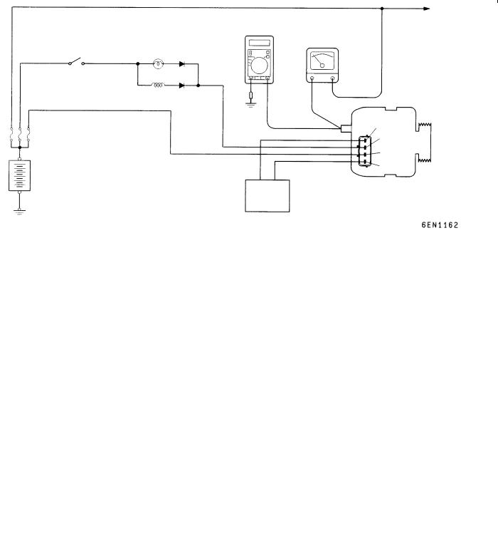
REGULATED VOLTAGE TEST
|
|
|
|
|
|
Load |
|
|
Ammeter |
|
|
||
Ignition |
|
|
|
|
|
|
MB991519 |
|
|
|
|
||
switch |
|
|
|
|
|
|
|
|
|
|
|
|
|
|
|
|
|
|
||
|
|
Black |
|
|
|
|
|
|
|
|
B |
FR |
Alternator |
|
|
|
|
|
L |
|
|
|
|
|
|
S |
|
|
|
|
|
|
G |
|
|
Voltmeter |
|
|
|||
|
Blue |
|
||||
Battery |
|
Red Yellow |
|
|||
|
|
|
||||
Engine-ECU
This test determines whether the voltage regulator is correctly controlling the alternator output voltage.
(1)Always be sure to check the following before the test.
D Alternator installation
D Check that the battery installed in the vehicle is fully charged.
(Refer to GROUP 54 - Battery.) D Alternator drive belt tension
(Refer to GROUP 11 - On-vehicle Service.) D Fusible link
D Abnormal noise from the alternator while the engine is running
(2)Turn the ignition switch to the “LOCK” (OFF) position.
(3)Disconnect the negative battery cable.
(4)Use the special tool (Alternator test harness: MB991519) to connect a digital voltmeter between the alternator S terminal and earth. (Connect the (+) lead of the voltmeter to the “S” terminal, and then connect the (−) lead of the voltmeter to a secure earth or to the battery (−) terminal.)
(5)Disconnect the alternator output wire from the alternator “B” terminal.
(6)Connect a DC test ammeter with a range of 0 - 100 A in series between the “B” terminal and the disconnected output wire. (Connect the (+) lead of the ammeter to the “B” terminal. Connect the (-) lead of the ammeter to the disconnected output wire.)
(7)Reconnect the negative battery cable.
(8)Connect a tachometer or the MUT-II. (Refer to GROUP 11 - On-vehicle Service.)
(9)Turn the ignition switch to the ON position and check that the reading on the voltmeter is equal to the battery voltage.
NOTE
If the voltage is 0 V, the cause is probably an open circuit in the wire or fusible link between the alternator “S” terminal and the battery (+) terminal.
(10)Turn all lamps and accessories off. (11)Start the engine.
(12)Increase the engine speed to 2,500 r/min. (13)Read the value displayed on the voltmeter when
the alternator output current alternator becomes 10 A or less.
16-8 |
ENGINE ELECTRICAL - Charging System |
|
|
(14)If the voltage reading conforms to the value in the voltage regulation, then the voltage regulator is operating normally.
If the voltage is not within the standard value, there is a malfunction of the voltage regulator or of the alternator.
(15)After the test, lower the engine speed to the idle speed.
(16)Turn the ignition switch to the “LOCK” (OFF) position.
Voltage Regulation Table
Standard value:
(17)Remove the tachometer or the MUT-II. (18)Disconnect the negative battery cable. (19)Disconnect the ammeter and voltmeter.
(20)Connect the alternator output wire to the alternator “B” terminal.
(21)Remove the special tool, and return the connector to the original condition.
(22)Connect the negative battery cable.
Inspection terminal |
Voltage regulator ambient temperature _C |
Voltage V |
||
|
|
|
|
|
Terminal “S” |
- 20 |
14.2 |
- 15.4 |
|
|
|
|
|
|
|
20 |
13.9 |
- 14.9 |
|
|
|
|
|
|
|
60 |
13.4 |
- |
14.6 |
|
|
|
|
|
|
80 |
13.1 |
- |
14.5 |
|
|
|
|
|
|
|
|
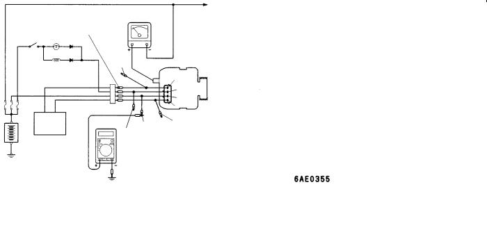
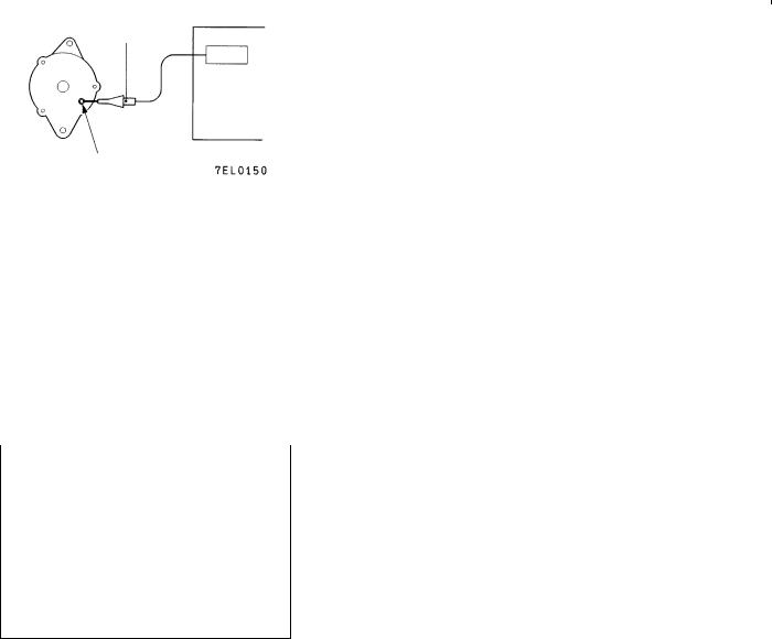
WAVEFORM CHECK USING AN ANALYZER |
|
|
Special |
Analyzer |
||
Alternator |
patterns |
MEASUREMENT METHOD |
||
|
||||
pickup |
|
|||
|
|
|
Connect the analyzer special patterns pick-up to the alternator |
|
|
|
|
B terminal. |
B terminal
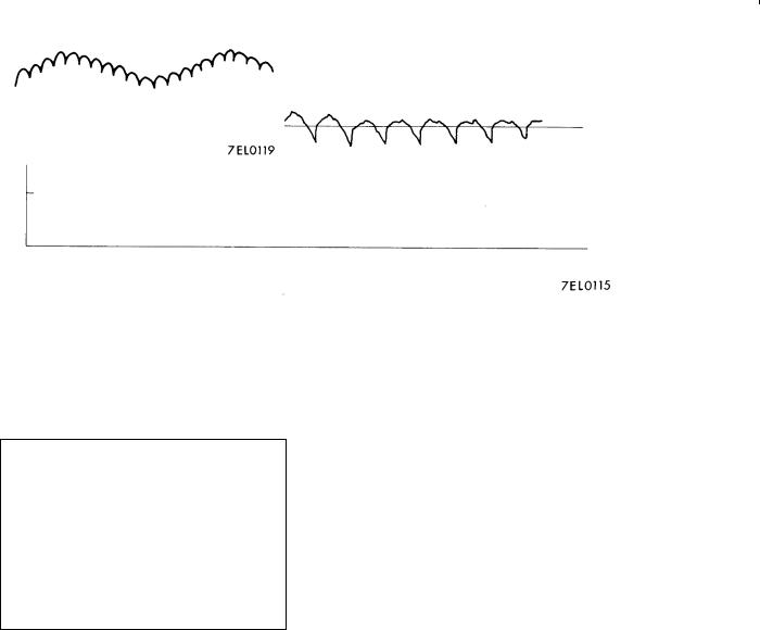
STANDARD WAVEFORM
Observation Conditions
FUNCTION |
SPECIAL PATTERNS |
|
|
PATTERN HEIGHT |
VARIABLE |
|
|
VARIABLE knob |
Adjust while viewing the wave- |
|
form. |
|
|
PATTERN SELECTOR |
RASTER |
|
|
Engine speed |
Curb idle speed |
|
|
ENGINE ELECTRICAL - Charging System |
16-9 |
|
|
0.4
0.2
Voltage at alternator 0 B terminal
-0.2
-0.4
Time
NOTE
The voltage waveform of the alternator B terminal can undulate as shown at left. This waveform is produced when the regulator operates according to fluctuations in the alternator load (current), and is normal for the alternator.
In addition, when the voltage waveform reaches an excessively high value (approximately 2 V or higher at idle), it often indicates an open circuit due to a brown fuse between alternator B terminal and battery, but not a defective alternator.

16-10 |
ENGINE ELECTRICAL - Charging System |
|
|
EXAMPLES OF ABNORMAL WAVEFORMS
NOTE
1.The size of the waveform patterns differs largely, depending on the adjustment of the variable knob on the analyzer.
2.Identification of abnormal waveforms is easier when there is a large output current (regulator is not operating). (Waveforms can be observed when the headlamps are illuminated.)
3.Check the conditions of the charging warning lamp (illuminated/not illuminated). Also, check the charging system totally.
Abnormal waveforms |
Problem |
Abnormal waveforms |
Problem |
|
cause |
|
cause |
|
|
|
|
Example 1 |
Open diode |
Example 4 |
Short in |
|
|
|
stator coil |
|
|
|
|
Example 2 |
Short in diode |
Example 5 |
Open |
|
|
|
supplementa- |
|
|
|
ry diode |
|
|
|
|
Example 3 |
Broken wire |
|
|
|
in stator coil |
|
|
|
|
At this time, the charging warning lamp |
|
|
|
is illuminated. |
|
|
|
|
|
ALTERNATOR
REMOVAL AND INSTALLATION
Caution
If the vehicle is equipped with the Brembo disc brake, during maintenance, take care not to contact the parts or tools to the caliper because the paint of caliper will be scratched.
Pre-removal and Post-installation Operation
D Under Cover Removal and Installation (Refer to GROUP 51 - Front Bumper.)
D Drive Belt Tension Check (Refer to GROUP 11A - On-vehicle Service.) <After installation only> D Strut Tower Bar Removal and Installation (Refer to GROUP 42.)
D Crossmember Bar Removal and Installation (Refer to GROUP 32 - Engine Roll Stopper, Centermember.) D Front Exhaust Pipe Assembly Removal and Installation (Refer to GROUP 15.)

ENGINE ELECTRICAL - Charging System |
16-11 |
|
|
13 ± 1
22
|
Removal steps |
|
|
|
|
|
1. |
Oil level gauge and guide assembly |
|
10. |
Insulator |
|
2. |
O-ring |
|
11. |
Insulator |
|
3. |
Fuel pressure solenoid valve |
AB" |
12. |
Drive belt |
|
|
connector |
|
13. |
Alternator connector |
|
4. |
Fuel pressure solenoid valve |
|
D |
Engine mounting |
|
|
assembly |
|
|
(Refer to GROUP 32.) |
|
5. |
Detonation sensor connector |
AC" |
14. |
Alternator |
|
6. |
Purge control solenoid valve |
|
15. |
Water pump pulley |
|
|
connector |
|
16. |
Alternator brace |
|
7. |
Purge control solenoid valve assembly |
|
17. |
Oxygen sensor connector |
|
8. |
Injector connector |
|
18. |
Alternator brace stay |
AA" |
9. Delivery pipe, injector, and fuel |
|
|
|
|
|
|
pressure regulator assembly |
|
|
|
16-12 |
ENGINE ELECTRICAL - Charging System |
|
|
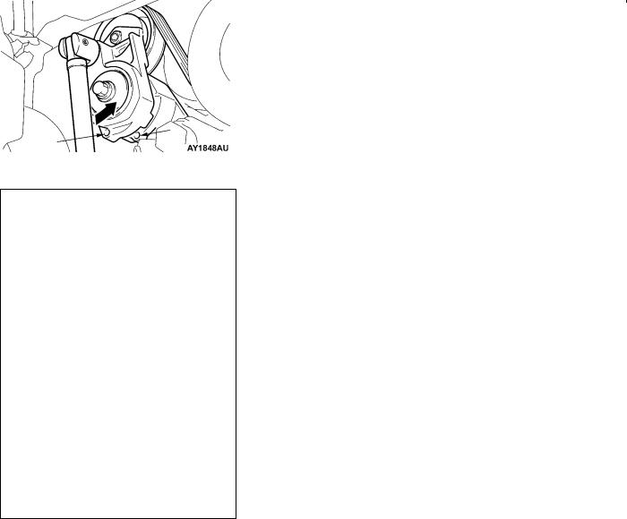
Hole B
L-shaped hexagon wrench
REMOVAL SERVICE POINTS
AA" DELIVERY PIPE, INJECTOR, AND FUEL
PRESSURE REGULATOR ASSEMBLY REMOVAL
After loosening the installed parts, set the related parts aside to make some space for removing the alternator.
AB" DRIVE BELT REMOVAL
Due to the adoption of the Serpentine drive system with the auto-tensioner, the following operation is required:
1.Insert the 12.7sq. spinner handle into the tool hole of the auto-tensioner and rotate it counterclockwise until the auto-tensioner reaches to the stopper.
2.Align hole A with hole B for fixing by inserting the L-shaped hexagon wrench, then remove the drive belt.
Caution
When the drive belt is reused, use a chalk to indicate an arrow of rotation direction on the back of the belt so that it can be re-assembled in the same direction as before.
AC"ALTERNATOR REMOVAL
Push up the engine with a garage jack to the top and remove the alternator upward from the engine room.
Loading...