


LANCER
WORKSHOP MANUAL
SUPPLEMENT
FOREWORD
This Workshop manual contains procedures for service mechanics, including removal, disassembly, inspection, adjustment, reassembly and installation. Use the following manuals in combination with this manual as required.
TECHNICAL INFORMATION MANUAL PYME0302 PYME0302-A PYME0302-B
WORKSHOP MANUAL
CHASSIS GROUP PWME0302 PWME0302-A PWME0302-B
BODY REPAIR MANUAL PBME0302 PBME0302-A PBME0302-B
PARTS CATALOGUE
B606K006A_
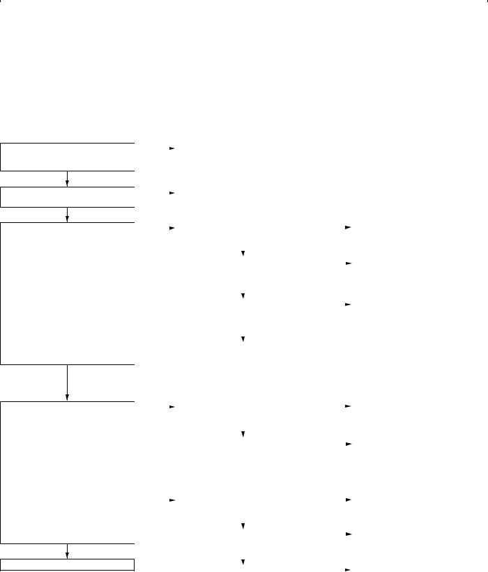
GROUP INDEX
General . . . . . . . . . . . . . . . . . . . . . . . . 00
Fuel . . . . . . . . . . . . . . . . . . . . . . . . . . . 13
All information, illustrations and product descriptions contained in this manual are current as at the time of publication. We, however, reserve the right to make changes at any time without prior notice or obligation.
©Mitsubishi Motors Corporation |
Oct. 2005 |

00-1
GROUP 00
GENERAL
CONTENTS
VEHICLE IDENTIFICATION . . . . . . . |
00-2 GENERAL DATA AND |
|
|
SPECIFICATIONS . . . . . . . . . . . . . . . |
00-3 |
00-2 |
GENERAL |
|
VEHICLE IDENTIFICATION |
VEHICLE IDENTIFICATION
MODELS |
|
|
|
M1001000401448 |
|
|
|
|
|
||
|
|
|
|
|
|
Model code |
Engine model |
Price class |
Transmission model |
Fuel supply |
|
|
|
|
|
|
system |
CS9A |
SRHML6 |
4G63-DOHC (1,997 mL) |
Intense |
F4A4B |
MPI |
|
|
|
|
<2WD, 4A/T> |
|
|
|
|
|
|
|
MODEL CODE
CS 9 W L N H M L 6
1 2 3 4 5 6 7 8 9
AC303950AC
No. |
Item |
Content |
1 |
Development |
CS: MITSUBISHI LANCER |
|
|
|
2 |
Engine type |
9: 1,997mL |
|
|
|
3 |
Sort |
A: Passenger car |
|
|
|
4 |
Body style |
S: 4-door sedan |
|
|
|
5 |
Transmission |
R: 4-speed automatic |
|
type |
transmission |
|
|
|
6 |
Trim level |
H: Intense |
|
|
|
7 |
Specification |
M: MPI-DOHC |
|
engine feature |
|
|
|
|
8 |
Steering wheel |
L: Left hand |
|
location |
|
|
|
|
9 |
Destination |
6: For Europe |
|
|
|
GENERAL |
00-3 |
GENERAL DATA AND SPECIFICATIONS |
|
GENERAL DATA AND SPECIFICATIONS
M1001000901197
7 |
1 |
2 |
8
3 |
4 |
5 |
|
6 |
|
9 |
AC303990AB
Items |
|
|
|
|
CS9A |
|
|
|
|
|
SRHML6 |
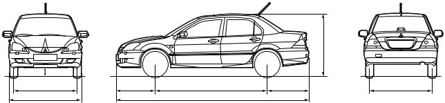
Vehicle dimensions mm |
Front track |
|
1 |
1,470 |
|
|
|
|
|
|
|
|
Overall width |
|
2 |
1,715 |
|
|
|
|
|
|
|
|
Front overhang |
|
3 |
965 |
|
|
|
|
|
|
|
|
Wheel base |
|
4 |
2,600 |
|
|
|
|
|
|
|
|
Rear overhang |
|
5 |
970 |
|
|
|
|
|
|
|
|
Overall length |
|
6 |
4,535 |
|
|
|
|
|
||
|
Ground clearance (unladen) |
7 |
135 |
||
|
|
|
|
||
|
Overall height (unladen) |
8 |
1,415 |
||
|
|
|
|
|
|
|
Rear track |
|
9 |
1,470 |
|
|
|
|
|
|
|
Vehicle weight kg |
Kerb weight |
|
|
1,295 |
|
|
|
|
|
||
|
Max. gross vehicle weight |
|
1,770 |
||
|
|
|
|
||
|
Max. axle weight rating-front |
|
930 |
||
|
|
|
|
||
|
Max. axle weight rating-rear |
|
840 |
||
|
|
|
|
|
|
|
Max. trailer weight |
|
With brake |
|
1,000 |
|
|
|
|
|
|
|
|
|
Without brake |
400 |
|
|
|
|
|
|
|
|
Max. trailer-nose weight |
|
|
|
60 |
|
|
|
|
|
|
Seating capacity |
|
|
|
|
5 |
|
|
|
|
|
|
Engine |
Model code |
|
|
4G63 |
|
|
|
|
|
|
|
|
Total displacement mL |
|
|
1,997 |
|
|
|
|
|
||
|
Maximum output kW/r/min |
|
99/5,750 |
||
|
|
|
|
||
|
Maximum torque N m/r/min |
|
176/4,500 |
||
|
|
|
|
|
|
Transmission |
Model code |
|
|
F4A4B |
|
|
|
|
|
|
|
|
Type |
|
|
4-speed automatic |
|
|
|
|
|
|
|
Fuel system |
Fuel supply system |
|
|
MPI |
|
|
|
|
|
|
|
Maximum speed km/h |
|
|
|
|
187 |
|
|
|
|
|
|
Minimum turning radius m |
|
|
|
|
5.7 |
|
|
|
|
|
|

NOTES

13D-1
MULTIPOINT FUEL INJECTION (MPI)
<4G63>
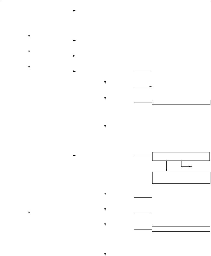
CONTENTS
GENERAL . . . . . . . . . . . . . . . . . . . . . . . . . . . . . . . . . 2
Outline of Change . . . . . . . . . . . . . . . . . . . . . . . . . . . . 2
GENERAL INFORMATION . . . . . . . . . . . . . . . . . . . 3 SERVICE SPECIFICATIONS . . . . . . . . . . . . . . . . . 6 SEALANT . . . . . . . . . . . . . . . . . . . . . . . . . . . . . . . . . . 6 SPECIAL TOOLS . . . . . . . . . . . . . . . . . . . . . . . . . . . 7 TROUBLESHOOTING . . . . . . . . . . . . . . . . . . . . . . 10 ON-VEHICLE SERVICE . . . . . . . . . . . . . . . . . . . . 90
Throttle Body (Throttle Valve Area)
Cleaning . . . . . . . . . . . . . . . . . . . . . . . . . . . . . . . . . . . 90
Throttle Position Sensor Adjustment . . . . . . . . . . . . 90
Basic Idle Speed Adjustment . . . . . . . . . . . . . . . . . . 91
Fuel Pressure Test . . . . . . . . . . . . . . . . . . . . . . . . . . . 92
Component Location . . . . . . . . . . . . . . . . . . . . . . . . . 95
Engine Control Relay Continuity Check . . . . . . . . . 96
Fuel Pump Relay Continuity Check . . . . . . . . . . . . . 96
Intake Air Temperature Sensor Check . . . . . . . . . . 97
Engine Coolant Temperature Sensor Check . . . . . 98
Throttle Position Sensor Check . . . . . . . . . . . . . . . . 98
Oxygen Sensor Check . . . . . . . . . . . . . . . . . . . . . . . 99
Injector Check . . . . . . . . . . . . . . . . . . . . . . . . . . . . . . 101
Idle Speed Control (ISC) Servo (Stepper Motor)
Check . . . . . . . . . . . . . . . . . . . . . . . . . . . . . . . . . . . . . 102
Purge Control Solenoid Valve Check . . . . . . . . . . 104 EGR Control Solenoid Valve Check . . . . . . . . . . . 104

13D-2 |
MPI <4G63> ï General |
GENERAL
OUTLINE OF CHANGE
Following service procedures have been established due to the addition of vehicles with 4G63-MPI engine for Russia.

MPI <4G63> ï General Information |
13D-3 |
GENERAL INFORMATION
The Multipoint Fuel Injection System consists of sensors which detect the engine conditions, the engine-A/T-ECU which controls the system based on signals from these sensors, and actuators which operate under the control of the engine-A/T-ECU. The engine-A/T-ECU
FUEL INJECTION CONTROL
The injector drive times and injection timing are controlled so that the optimum air/fuel mixture is supplied to the engine to correspond to the continually-changing engine operation conditions.
A single injector is mounted at the intake port of each cylinder. Fuel is sent under pressure from the fuel tank by the fuel pump, with the pressure being regulated by the fuel pressure regulator. The fuel thus regulated is distributed to each of the injectors.
Fuel injection is normally carried out once for each cylinder for every two rotations of the crankshaft. The firing order is 1ï3ï4ï2. This is called sequential fuel injection. The
IDLE AIR CONTROL
The idle speed is kept at the optimum speed by controlling the amount of air that bypasses the throttle valve in accordance with changes in idling conditions and engine load during idling. The engine-A/T-ECU drives the idle speed control motor to keep the engine running at the pre-set idle target speed in accordance with the engine coolant temperature and air
IGNITION TIMING CONTROL
The power transistor located in the ignition primary circuit turns ON and OFF to control the primary current flow to the ignition coil. This controls the ignition timing in order to provide the optimum ignition timing with respect to the
SELF-DIAGNOSIS FUNCTION
DWhen an abnormality is detected in one of the sensors or actuators related to
emission control, the engine warning lamp (check engine lamp) illuminates as a warning to the driver.
DWhen an abnormality is detected in one of the sensors or actuators, a diagnosis
carries out activities such as fuel injection control, idle speed control and ignition timing control. In addition, the engine-A/T-ECU is equipped with several diagnosis modes which simplify troubleshooting when a problem develops.
engine-A/T-ECU provides a richer air/fuel mixture by carrying out “open-loop” control when the engine is cold or operating under high load conditions in order to maintain engine performance. In addition, when the engine is warm or operating under normal conditions, the engine-A/T-ECU controls the air/fuel mixture by using the oxygen sensor signal to carry out “closed-loop” control in order to obtain the theoretical air/fuel mixture ratio that provides the maximum cleaning performance from the three way catalyst.
conditioner load. In addition, when the air conditioner switch is turned off and on while the engine is idling, the idle speed control motor operates to adjust the throttle valve bypass air amount in accordance with the engine load conditions in order to avoid fluctuations in the engine speed.
engine operating conditions. The ignition timing is determined by the engine-A/T-ECU from the engine speed, intake air volume, engine coolant temperature and atmospheric pressure.
code corresponding to the abnormality is output.
DThe RAM data inside the engine-A/T-ECU that is related to the sensors and actuators can be read by means of the M.U.T.-II/III. In addition, the actuators can be force-driven under certain circumstances.

13D-4 MPI <4G63> ï General Information
OTHER CONTROL FUNCTIONS
1.Fuel Pump Control
Turns the fuel pump relay ON so that current is supplied to the fuel pump while the engine is cranking or running.
2.A/C Relay Control
Turns the compressor clutch of the A/C ON and OFF.
3.Fan Motor Control
The revolutions of the radiator fan and condenser fan are controlled in response to the engine coolant temperature and vehicle speed.
4.Purge Control Solenoid Valve Control
5.EGR Control Solenoid Valve Control
GENERAL SPECIFICATIONS
Item |
|
Specification |
|
|
|
Throttle body |
Throttle bore mm |
60 |
|
|
|
|
Throttle position sensor |
Variable resistor type |
|
|
|
|
Idle speed control servo |
Stepper motor type |
|
|
|
Engine-A/T- |
Identification No. |
E6T37983 |
ECU |
|
|
|
|
|
Sensors |
Air flow sensor |
Karman vortex type |
|
|
|
|
Barometric pressure sensor |
Semiconductor type |
|
|
|
|
Intake air temperature sensor |
Thermistor type |
|
|
|
|
Engine coolant temperature sensor |
Thermistor type |
|
|
|
|
Oxygen sensor |
Zirconia type |
|
|
|
|
Inhibitor switch |
Contact switch type |
|
|
|
|
Camshaft position sensor |
Hall element type |
|
|
|
|
Crank angle sensor |
Hall element type |
|
|
|
|
Detonation sensor |
Piezoelectric type |
|
|
|
|
Power steering fluid pressure switch |
Contact switch type |
|
|
|
Actuators |
Engine control relay |
Contact switch type |
|
|
|
|
Fuel pump relay |
Contact switch type |
|
|
|
|
Injector type and number |
Electromagnetic type, 4 |
|
|
|
|
Injector identification mark |
HDA250E |
|
|
|
|
EGR control solenoid valve |
Duty cycle type solenoid valve |
|
|
|
|
Purge control solenoid valve |
Duty cycle type solenoid valve |
|
|
|
Fuel pressure |
Regulator pressure kPa |
328 |
regulator |
|
|
|
|
|
|
|
MPI <4G63> ï General Information |
13D-5 |
||||||
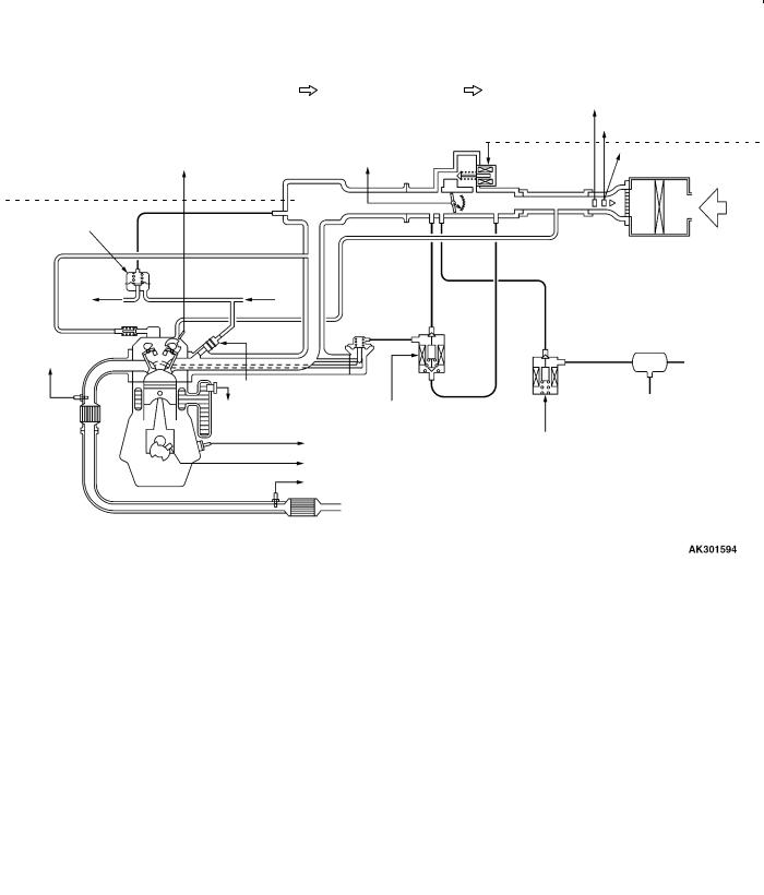
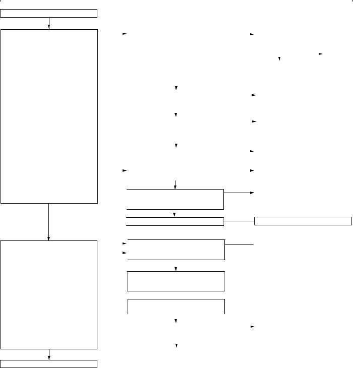
MULTI-POINT FUEL INJECTION SYSTEM DIAGRAM |
|
|
|
|
|||||
|
|
|
|
|
|
|
|
|
|
|
L1 |
Oxygen sensor (front) |
|
|
|
l1 Injector |
|
|
|
|
L2 |
Oxygen sensor (rear) |
|
|
|
l2 Idle speed control servo |
|
||
|
L3 |
Air flow sensor |
|
Engine-A/T-ECU |
|
|
(Stepper motor) |
|
|
|
L4 Intake air temperature sensor |
|
|
|
l3 EGR control solenoid valve |
|
|||
|
L5 |
Throttle position sensor |
|
|
|
l4 Purge control solenoid valve |
|
||
|
L6 Camshaft position sensor |
|
|
|
|
|
|
|
|
|
L7 Crank angle sensor |
|
|
|
|
|
|
|
|
|
L8 Barometric pressure sensor |
|
|
|
D |
Engine control relay |
|
||
|
L9 Engine coolant temperature sensor |
|
|
|
|
||||
|
L10 Detonation sensor |
|
|
|
D |
Fuel pump relay |
|
||
|
|
|
|
|
|
D |
A/C compressor relay |
|
|
|
D |
Power supply |
|
|
|
D |
Ignition |
coil |
|
|
|
|
|
D |
Fan controller |
|
|||
|
D |
Ignition switch-IG |
|
|
|
D Air flow sensor filter reset signal |
|
||
|
D |
Ignition switch-ST |
|
|
|
D |
Engine warning lamp |
|
|
|
D |
A/C switch |
|
|
|
D |
Diagnosis output |
|
|
|
D |
A/C load signal |
|
|
|
D |
Alternator G terminal |
|
|
|
D Power steering fluid pressure switch |
|
|
|
D |
Oxygen sensor (front) heater |
|
||
|
D |
Alternator FR terminal |
|
|
|
D |
Oxygen sensor (rear) heater |
|
|
|
D |
Vehicle speed sensor |
|
|
|
D |
Tachometer |
|
|
|
|
|
|
|
|
|
|
|
|
|
|
|
|
|
|
|
|
|
|
|
|
L4 Intake air temperature sensor |
|
|
l2 Idle speed control servo |
L3 Air flow sensor |
|
|
(Stepper motor) |
L8 Barometric |
|
|
L5 Throttle position |
|
|
L6 Camshaft position sensor |
|
pressure sensor |
|
|
sensor |
|
|
Fuel pressure |
|
|
Air |
regulator |
M M |
A |
|
|
|
||
To
fuel tank
L1 Oxygen sensor (front)
Catalytic converter
From fuel pump
EGR valve
|
|
|
Canister |
l1 Injector |
|
|
|
L9 Engine coolant |
|
l3 EGR control |
|
temperature sensor |
solenoid valve |
|
|
L10 Detonation sensor |
l4 Purge control |
||
L7 |
Crank angle sensor |
solenoid valve |
|
|
|||
L2 |
Oxygen sensor (rear) |
|
|
Catalytic converter
13D-6 |
MPI <4G63> ï Service Specifications/Sealant |
|||
SERVICE SPECIFICATIONS |
|
|||
|
|
|
|
|
Items |
|
|
|
Specifications |
|
|
|
|
|
Basic idle speed |
r/min |
|
|
750 r 50 |
|
|
|
|
|
Throttle position sensor adjusting voltage |
mV |
535 ï 735 |
||
|
|
|
|
|
Throttle position sensor resistance k: |
|
3.5 ï 6.5 |
||
|
|
|
||
Idle speed control servo coil resistance (at 20_C) : |
28 ï 33 |
|||
|
|
|
|
|
Intake air temperature sensor |
ï20_C |
|
13 ï 17 |
|
resistance k: |
|
|
|
|
|
0_C |
|
5.3 ï 6.7 |
|
|
|
|
||
|
|
|
|
|
|
|
20_C |
|
2.3 ï 3.0 |
|
|
|
|
|
|
|
40_C |
|
1.0 ï 1.5 |
|
|
|
|
|
|
|
60_C |
|
0.56 ï0.76 |
|
|
|
|
|
|
|
80_C |
|
0.30 ï 0.42 |
|
|
|
|
|
Engine coolant temperature |
ï20_C |
|
14 ï 17 |
|
sensor resistance |
k: |
|
|
|
0_C |
|
5.1 ï 6.5 |
||
|
|
|
||
|
|
|
|
|
|
|
20_C |
|
2.1 ï 2.7 |
|
|
|
|
|
|
|
40_C |
|
0.9 ï 1.3 |
|
|
|
|
|
|
|
60_C |
|
0.48 ï 0.68 |
|
|
|
|
|
|
|
80_C |
|
0.26 ï 0.36 |
|
|
|
|
|
Oxygen sensor output voltage (at racing) |
V |
0.6 ï 1.0 |
||
|
|
|
|
|
Oxygen sensor heater |
front |
|
4.5 ï 8.0 |
|
resistance (at 20_C) : |
|
|
|
|
rear |
|
11 ï 18 |
||
|
|
|
||
|
|
|
||
Fuel pressure kPa |
Vacuum hose disconnection |
324 ï 343 at kerb idle |
||
|
|
|
|
|
|
|
Vacuum hose connection |
Approximately 265 at kerb idle |
|
|
|
|
|
|
Injector coil resistance (at 20_C) : |
|
10.5 ï 13.5 |
||
|
|
|
|
|
SEALANT
Item |
Specified sealant |
Remark |
|
|
|
Engine coolant temperature sensor |
3M Nut Locking Part No. 4171 or equivalent |
Drying sealant |
threaded portion |
|
|
|
|
|

|
|
MPI <4G63> ï Special Tools |
13D-7 |
|||
SPECIAL TOOLS |
|
|
|
|
|
|
|
|
|
|
|
|
|
Tool |
|
Number |
Name |
Use |
|
|
|
|
|
|
|
|
|
|
|
MB991502 |
M.U.T.-II sub |
D |
Reading diagnosis code |
|
|
|
|
assembly |
D |
MPI system inspection |
|
|
|
|
|
D Measurement of fuel pressure |
|
|
|
|
|
|
|
|
|
MB991955 |
M.U.T.-III sub |
D |
Reading diagnosis code |
A: MB991824 |
assembly |
D |
MPI system inspection |
B: MB991827 |
|
D Measurement of fuel pressure |
|
|
|
|
|
C: MB991910 |
|
|
|
D: MB991911 |
|
|
|
E: MB991825 |
|
|
|
F: MB991826 |
|
|
|
M.U.T.-III sub |
|
|
|
assembly |
|
|
|
A:Vehicle communication interface (V.C.I.)
B:M.U.T.-III USB cable
C:M.U.T.-III main harness A (Vehicles with CAN communication system)
D:M.U.T.-III main harness B (Vehicles without CAN communication system)
E:M.U.T.-III measurement adapter
F:M.U.T.-III trigger harness
|
MB991348 |
Test harness set |
D Inspection using an oscilloscope |
|
|
|
|

13D-8 |
MPI <4G63> ï Special Tools |
||||
|
|
|
|
|
|
Tool |
Number |
Name |
|
Use |
|
|
|
|
|
|
|
|
MB991709 |
Test harness |
D |
Measurement of voltage during |
|
|
|
|
|
|
troubleshooting |
|
|
|
|
D |
Inspection using an oscilloscope |
|
|
|
|
D |
Check of idle speed control servo |
|
|
|
|
|
|
|
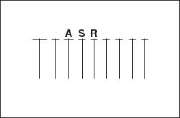
MD998478 |
Test harness |
D |
Measurement of voltage during |
|
|
|
(3-pin, triangle) |
|
Troubleshooting |
|
|
|
|
|
D |
Inspection using an oscilloscope |
|
|
|
|
|
|
|
MB991536 |
Check harness for |
D |
Measurement of voltage during |
|
|
|
throttle |
position |
|
Troubleshooting |
|
|
sensor adjustment |
D |
Adjusting of throttle position sensor |
|
|
|
|
|
|
|
|
MD998464 |
Test harness |
D |
Measurement of voltage during |
|
|
|
(4-pin, square) |
|
Troubleshooting |
|
|
|
|
|
D |
Inspection of oxygen sensor (front) |
|
|
|
|
|
|
|
MB991658 |
Test harness |
D |
Measurement of voltage during |
|
|
|
|
|
|
Troubleshooting |
|
|
|
|
D |
Inspection of oxygen sensor (rear) |
|
|
|
|
|
|
|
MB991223 |
Harness set |
D |
Check at the ECU terminals |
|
|
A: MB991219 |
A: Test harness |
A: |
Connector pin contact pressure inspection |
|
|
B: MB991220 |
B: LED harness |
B: |
Power circuit inspection |
|
|
C: |
Power circuit inspection |
|||
|
C: MB991221 |
C: LED harness |
|||
|
D: |
Commercial tester connection |
|||
|
D: MB991222 |
adapter |
|
||
|
|
|
|
||
|
|
D: Probe |
|
|
|
|
|
|
|
|
|
|
MPI <4G63> ï Special Tools |
13D-9 |
||
|
|
|
|
|
Tool |
Number |
Name |
Use |
|
|
|
|
|
|
|
MD998709 |
Adaptor hose |
Measurement of fuel pressure |
|
|
|
|
|
|
|
MD998742 |
Hose adaptor |
|
|
|
|
|
|
|
|
MB991637 |
Fuel pressure |
|
|
|
|
gauge set |
|
|
|
|
|
|
|
|
MB991981 |
Fuel pressure |
|
|
|
|
gauge set |
|
|
|
|
|
|
|
|
MB992076 |
Injector test set |
Checking the spray condition of injectors |
|
|
|
|
|
|
|
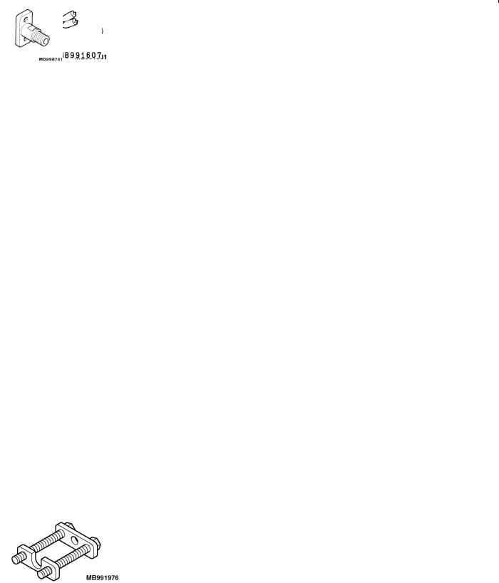
MB991607 |
Injector test |
|
|
|
|
harness |
|
|
|
|
|
|
|
|
MD998741 |
Injector test |
|
|
|
|
adaptor |
|
|
|
|
|
|
|
|
MB991976 |
Injector test holder |
|
|
|
|
assembly |
|
|
|
|
|
|
|

13D-10 |
MPI <4G63> ï Troubleshooting |
Engine warning lamp (check engine lamp)
TROUBLESHOOTING
DIAGNOSIS TROUBLESHOOTING FLOW
Refer to GROUP 00 ï How to Use Troubleshooting/Inspection Service Point.
NOTE
If the engine-A/T-ECU is replaced, ring antenna with built in immobilizer-ECU should be replaced, ignition key can be kept, but must be registered.
DIAGNOSIS FUNCTION
ENGINE WARNING LAMP (CHECK ENGINE LAMP)
If an abnormality occurs in any of the following items related to the MPI system, the engine warning lamp will illuminate or flash. If the lamp remains illuminated or if the lamp illuminates while the engine is running, check the diagnosis code output.
However, the warning lamp will illuminate as bulb check for five seconds whenever the ignition switch is turned to the ON position.
Engine warning lamp inspection items
Engine-A/T-ECU
Oxygen sensor (front)
Air flow sensor
Intake air temperature sensor
Throttle position sensor
Engine coolant temperature sensor
Crank angle sensor
Camshaft position sensor
Barometric pressure sensor
Detonation sensor
Ignition coil, power transistor unit
Injector
Immobilizer system
Oxygen sensor (rear)
NOTE
If the engine warning lamp illuminates because of a malfunction of the engine-A/T-ECU, communication between M.U.T.-II/III and the engine-A/T-ECU is impossible. In this case, the diagnosis code cannot be read.

MPI <4G63> ï Troubleshooting |
13D-11 |
METHOD OF READING AND ERASING DIAGNOSIS
CODES
Refer to GROUP 00 ï How to Use Troubleshooting/Inspection
Service Points.
INSPECTION USING M.U.T.-II/III DATA LIST AND
ACTUATOR TESTING
1.Carry out inspection by means of the data list and the actuator test function. If there is an abnormality, check and repair the chassis harnesses and components.
2.After repairing, re-check using the M.U.T.-II/III and check that the abnormal input and output have returned to normal as a result of the repairs.
3.Erase the diagnosis code memory.
4.Remove the M.U.T.-II/III, and then start the engine again and carry out a road test to confirm that the problem has disappeared.
FAIL-SAFE FUNCTION REFERENCE TABLE
When the main sensor malfunctions are detected by the diagnosis function, the vehicle is controlled by means of the pre-set control logic to maintain safe conditions for driving.
Malfunctioning item |
Control contents during malfunction |
|
|
Air flow sensor |
1. Uses the throttle position sensor signal and engine speed signal (crank angle sensor |
|
signal) to take reading of the basic injector drive time and basic ignition timing from |
|
the pre-set mapping. |
|
2. Fixes the ISC servo in the appointed position so idle control is not performed. |
|
|
Intake air temperature |
Controls as if the intake air temperature is 25_C. |
sensor |
|
|
|
Throttle position |
No increase in fuel injection amount during acceleration due to the throttle position sensor |
sensor (TPS) |
signal. |
|
|
Engine coolant |
Controls as if the engine coolant temperature is 80_C. |
temperature sensor |
|
|
|
Camshaft position |
Injects fuel into the cylinders in the order 1-3-4-2 with irregular timing. |
sensor |
(However, after the ignition switch is turned to ON, the No. 1 cylinder top dead centre is not |
|
detected at all.) |
|
|
Barometric pressure |
Controls as if the barometric pressure is 101 kPa. |
sensor |
|
|
|
Detonation sensor |
Switches the ignition timing from ignition timing for super petrol to ignition timing for standard |
|
petrol. |
|
|
Ignition coil, power |
Cuts off the fuel supply to cylinders with an abnormal ignition. |
transistor |
|
|
|
Alternator FR terminal |
Does not control the output of the alternator according to an electrical load. (works as a |
|
normal alternator) |
|
|

13D-12 |
MPI <4G63> ï Troubleshooting |
|
INSPECTION CHART FOR DIAGNOSIS CODES |
|
|
|
|
|
Code No. |
Diagnosis item |
Reference page |
|
|
|
11 |
Oxygen sensor (front) system |
13D-13 |
|
|
|
12 |
Air flow sensor system |
13D-15 |
|
|
|
13 |
Intake air temperature sensor system |
13D-16 |
|
|
|
14 |
Throttle position sensor system |
13D-18 |
|
|
|
21 |
Engine coolant temperature sensor system |
13D-20 |
|
|
|
22 |
Crank angle sensor system |
13D-22 |
|
|
|
23 |
Camshaft position sensor system |
13D-23 |
|
|
|
24 |
Vehicle speed signal system |
13D-25 |
|
|
|
25 |
Barometric pressure sensor system |
13D-26 |
|
|
|
31 |
Detonation sensor system |
13D-28 |
|
|
|
41 |
Injector system |
13D-29 |
|
|
|
44 |
Ignition coil (power transistor) system |
13D-30 |
|
|
|
54 |
Immobilizer system |
13D-31 |
|
|
|
59 |
Oxygen sensor (rear) system |
13D-32 |
|
|
|
64 |
Alternator FR terminal system |
13D-34 |
|
|
|
NOTE
1.Do not replace the engine-A/T-ECU until a through terminal check reveals there are no short/open circuit.
2.Check that the engine-A/T-ECU earth circuit is normal before checking for the cause of the problem.
MPI <4G63> ï Troubleshooting |
13D-13 |
||
INSPECTION PROCEDURE FOR DIAGNOSIS CODE |
|
|
|
|
|
|
|
Code No. 11 Oxygen sensor (front) system |
|
Probable cause |
|
|
|
|
|
Range of Check |
|
D Malfunction of the oxygen sensor (front) |
|
D More than 3 minutes passed after completion of start of engine |
|
D Oxygen sensor (front) circuit disconnection, |
|
D The engine coolant temperature is approximately more than 80_C. |
|
short-circuit, or connector contact defect. |
|
D Intake air temperature 0 ï 55_C. |
|
D Malfunction of the engine-A/T-ECU |
|
D The engine speed is more than 1,800 ï 3,500 r/min. |
|
|
|
D The volumetric efficiency is 16 ï 60% or more. |
|
|
|
Set Conditions |
|
|
|
D For 30 seconds, the oxygen sensor output voltage continues to be 0.5 V or |
|
|
|
lower, or 0.5 V or higher. |
|
|
|
D The Engine-A/T-ECU monitors for this condition once during the drive cycle. |
|
|
|
|
|
|
|
M.U.T.-II/III Data list
DNo. 11 Oxygen sensor (front) (Refer to P.13D-66.)
NG
Check the following connector:
B-17
OK
Measure at the B-17 oxygen sensor (front) connector.
DDisconnect connector to measure at the harness side
DResistance between terminal No. 2 and earth.
OK: Less than 2 :
OK
Measure at the B-17 oxygen sensor (front) connector.
DUsing the test harness (MD998464), connect the
connector, and measure at the pickup harness.
D Engine: After warm-up
(1)Voltage between terminal No. 2 and earth
OK: Less than 0.5 V
(2)Voltage between terminal No. 4
and the earth
D At rapid deceleration from 4,000 r/min
OK: 200 mV or less
DDuring rapid racing OK: 600 ï 1,000 mV
OK
To the next page
|
OK |
|
|
|
|
|
||
|
Intermittent malfunction |
|
|
|
|
|||
|
|
|
|
|
|
|
||
|
|
|
|
|
|
|
||
|
|
|
(Refer to GROUP 00 ï Points to Note |
|
|
|
|
|
|
|
|
for Intermittent Malfunctions.) |
|
|
|
|
|
|
|
|
|
|
|
|
||
|
NG |
|
|
|
|
|||
|
|
|
|
|
||||
|
|
|
Repair |
NG |
|
|
|
|
|
NG |
|
Repair |
|||||
|
|
|
||||||
|
|
|
|
|||||
|
Check the following connector: |
|
||||||
|
|
|
|
|
||||
|
|
|
|
|
||||
|
|
|
C-124 |
|
|
|
|
|
|
|
|
|
|
|
|
|
|
|
|
|
|
OK |
|
|
|
|
|
|
|
|
|
NG |
|
|
|
|
|
|
Check the harness between the |
|
Repair |
|||
|
|
|
|
|
||||
|
|
|
|
|
||||
|
|
|
oxygen sensor (front) and |
|
|
|
|
|
|
|
|
engine-A/T-ECU. |
|
|
|
|
|
|
|
|
|
|
|
|
|
|
|
|
|
|
OK |
|
|
|
|
|
|
|
|
|
NG |
|
|
|
|
|
|
M.U.T.-II/III Data list |
|
|
Replace the engine-A/T-ECU. |
|
|
|
|
|
D No. 11 Oxygen sensor (front) |
|
|
|
|
|
|
|
|
|
|
|
|
||
|
|
|
(Refer to P.13D-66.) |
|
|
|
|
|
|
|
|
|
|
|
|
|
|
|
|
|
|
OK |
|
|
|
|
|
|
|
|
|
|
|
|
|
|
|
|
Intermittent malfunction |
|
|
|
|
|
|
|
|
(Refer to GROUP 00 ï Points to Note |
|
|
|
|
|
|
(1) NG |
for Intermittent Malfunctions.) |
NG |
|
Repair |
|||
|
|
|||||||
|
|
|
||||||
|
|
|
|
|||||
|
Check the following connector: |
|
||||||
|
|
|
|
|
||||
|
|
|
|
|
||||
|
|
|
C-124 |
|
|
|
|
|
|
|
|
|
|
|
|
|
|
|
|
|
|
OK |
|
|
|
|
|
|
|
|
|
NG |
|
|
|
|
|
|
Check the harness between the |
|
Repair |
|||
|
|
|
|
|
||||
|
|
|
|
|
||||
|
|
|
oxygen sensor (front) and |
|
|
|
|
|
|
|
|
engine-A/T-ECU. |
|
|
|
|
|
|
(2) NG |
|
NG |
|
|
|
||
|
|
|
|
|
|
|||
|
|
|
Check the oxygen sensor (front). |
|
|
Replace the oxygen sensor (front). |
||
|
|
|
(Refer to P.13D-99.) |
|
|
|
|
|
|
|
|
|
|
|
|
|
|
|
|
|
|
OK |
|
|
|
|
|
|
|
|
|
NG |
|
Repair |
|
|
|
|
Check the following connector: |
|
|
|||
|
|
|
C-126 |
|
|
|
|
|
|
|
|
|
|
|
|
||
|
|
|
|
|
|
|
|
|
|
|
|
|
OK |
|
|
|
|
|
|
|
|
|
NG |
|
Repair |
|
|
|
|
|
|
|
|||
|
|
|
Check the harness between the |
|
|
|||
|
|
|
oxygen sensor (front) and |
|
|
|
|
|
|
|
|
engine-A/T-ECU. |
|
|
|
|
|
|
|
|
|
|
|
|
|
|

13D-14 |
MPI <4G63> ï Troubleshooting |
From the previous page |
|
|
|
|
|
||||
|
|
|
|
|
|
|
|
|
|
|
|
OK |
|
|
|
|
|||
|
|
|
NG |
|
|
|
NG |
||
Measure at the C-126 engine-A/T-ECU |
|
|
|
Check the following connector: |
|
Repair |
|||
|
|
|
|
||||||
connector. |
|
C-126 |
|
|
|||||
D Measure the engine-A/T-ECU |
|
|
|
|
|
||||
|
|
OK |
|
|
|||||
|
terminal voltage. |
|
|
|
|||||
|
|
|
|
|
|||||
D |
Engine: After warm-up |
Check and repair the harness between |
|
|
|||||
D |
Voltage between terminal No. 71 |
|
|
||||||
the oxygen sensor (front) and |
|
|
|||||||
|
and earth. |
|
|
||||||
|
engine-A/T-ECU. |
|
|
||||||
D |
At rapid deceleration from 4,000 |
|
|
||||||
|
|
|
|
||||||
|
r/min |
|
|
|
|
||||
|
OK: 200 mV or less |
|
|
|
|
||||
DDuring rapid racing OK: 600 ï 1,000 mV
|
OK |
|
|
|
|
|
NG |
||
Check the following connectors: |
|
|
Repair |
|
|
|
|||
C-124, C-126 |
|
|
|
|
|
|
|
|
|
|
OK |
|
|
|
|
|
NG |
|
|
M.U.T.-II/III Data list |
|
|
Replace the engine-A/T-ECU. |
|
D No. 11 Oxygen sensor (front) |
|
|
|
|
|
|
|
||
(Refer to P.13D-66.) |
|
|
|
|
|
OK |
|
|
|
|
|
|
|
|
Intermittent malfunction |
|
|
|
|
(Refer to GROUP 00 ï Points to Note |
|
|
|
|
for Intermittent Malfunctions.) |
|
|
|
|
|
|
|
|
|

MPI <4G63> ï Troubleshooting |
13D-15 |
|
|
|
|
Code No. 12 Air flow sensor system |
Probable cause |
|
|
|
|
Range of Check |
D Malfunction of the air flow sensor |
|
D The engine speed is more than 500 r/min |
D Air flow sensor circuit disconnection, short-circuit, |
|
Set Condition |
or connector contact defect |
|
D The sensor output frequency is less than 3.3 Hz for 4 seconds. |
D Malfunction of the engine-A/T-ECU |
|
|
|
|
M.U.T.-II/III Data list
DNo. 12 Air flow sensor (Refer to P.13D-66.)
NG
Check the following connector:
B-08
OK
Measure at the B-08 air flow sensor connector.
DDisconnect the connector to measure at the harness side
(1)Voltage between terminal No. 3 and earth
(Ignition switch: ON) OK: 4.9 ï 5.1 V
(2)Voltage between terminal No. 4 and earth
(Ignition switch: ON) OK: System voltage
(3)Resistance between terminal No. 5 and earth
OK: Less than 2 :
OK
To the next page
OK
 Intermittent malfunction
(Refer to GROUP 00 ï Points to Note for Intermittent Malfunctions.)
NG
 Repair
(1) NG |
|
|
|
OK |
||
Measure at the C-124 engine-A/T-ECU |
||||||
|
|
|
||||
|
||||||
|
|
connector. |
|
|||
|
|
D Measure the voltage of the |
|
|||
|
|
|
engine-A/T-ECU terminal. |
|
||
|
|
D |
Ignition switch: ON |
|
||
|
|
D Voltage between terminal No. 65 |
|
|||
|
|
|
and earth. |
|
||
|
|
|
OK: 4.9 ï 5.1 V |
|
||
|
|
|
|
|
|
|
|
|
|
|
NG |
||
|
|
|
|
|
|
|
Check the following connector: NG C-124
OK
 NG Check the harness between the air
flow sensor and engine-A/T-ECU.
OK
NG
M.U.T.-II/III Data list
DNo. 12 Air flow sensor (Refer to P.13D-66.)
|
|
|
OK |
|
|
|
|
|
|
|
|||
|
Intermittent malfunction |
|
|
|||
|
(Refer to GROUP 00 ï Points to Note |
|
|
|||
|
for Intermittent Malfunctions.) |
|
|
|||
(2) NG |
|
|
|
|
|
NG |
|
|
|
|
|
||
Check the following connector: |
|
|||||
|
|
|
||||
|
B-16X |
|
|
|
|
|
|
|
|
|
|
|
|
|
|
|
OK |
|
|
|
|
|
|
|
|
||
|
Check the harness between the air |
|
|
|||
|
flow sensor and engine control relay. |
|
|
|||
(3) NG |
|
|
|
|
|
NG |
|
|
|
|
|
||
|
Check the following connector: |
|
|
|
||
|
|
|
||||
|
C-122 |
|
|
|
|
|
|
|
|
|
|
|
|
|
|
|
OK |
|
|
|
|
|
|
|
|
|
NG |
|
Check the harness between the air |
|
|
|
||
|
flow sensor and engine-A/T-ECU. |
|
|
|
||
|
|
|
|
|
|
|
|
|
|
OK |
|
NG |
|
|
|
|
|
|
|
|
|
M.U.T.-II/III |
Data list |
||||
|
|
|
||||
DNo. 12 Air flow sensor (Refer to P.13D-66.)
OK
Intermittent malfunction
(Refer to GROUP 00 ï Points to Note for Intermittent Malfunctions.)
 Check the following connector:
C-124
OK NG
Repair
Check and repair the harness between the air flow sensor and engine-A/T- ECU.
 Repair
 Repair

 Replace the engine-A/T-ECU.
 Repair
 Repair
 Repair
 Replace the engine-A/T-ECU.
13D-16 |
MPI <4G63> ï Troubleshooting |
|
|
|
||||||||||||
|
|
|
|
|
|
|
|
|
|
|
|
|
|
|||
From the previous page |
|
|
|
|
|
|
|
|
|
|
|
|
|
|
||
|
|
|
|
|
|
|
|
|
|
|
|
|
|
|
|
|
|
|
OK |
|
|
|
|
|
NG |
|
|
|
|
||||
|
|
|
|
NG |
|
|
|
|
|
|
|
|
|
|||
Measure at the B-08 air flow sensor |
|
|
|
Check the following connector: |
|
|
|
Repair |
|
|||||||
connector. |
|
|
|
C-122 |
|
|
|
|
||||||||
D |
Using the test harness |
|
|
|
|
OK |
|
|
|
|||||||
|
(MB991709), connect the |
|
|
|
|
|
|
|
||||||||
|
|
|
|
|
|
|
NG |
|
|
|
||||||
|
connector, and measure at the |
|
|
|
Check the harness between the air |
|
|
Repair |
||||||||
D |
pickup. |
|
|
|
flow sensor and engine-A/T-ECU. |
|
|
|
|
|||||||
Ignition switch: ON |
|
|
|
|
|
|
|
|
|
|
|
|
|
|||
|
|
|
OK |
|
|
|
||||||||||
D Voltage between terminal No. 7 |
|
|
|
|
|
|
|
|||||||||
|
|
|
|
|
|
|
|
|
|
|
|
|
||||
|
and earth. |
|
|
|
|
|
|
|
|
|
|
|
|
|
||
|
|
|
Replace the air flow sensor. |
|
|
|
|
|
|
|
|
|||||
|
OK: 7 ï 8 V |
|
|
|
|
|
|
|
||||||||
|
|
|
|
|
|
|
|
|
|
|
|
|
|
|||
|
|
|
|
|
|
|
|
|
|
|
|
|
||||
|
|
|
|
|
|
|
|
|
|
|
|
|
|
|
|
|
|
|
OK |
|
|
|
|
|
|
|
|
|
|
|
|
||
|
|
|
|
NG |
|
|
|
|
|
NG |
|
|
|
|
||
|
|
|
|
|
|
|
|
|
|
|
|
|||||
Measure at the B-08 air flow sensor |
|
|
|
Check the following connector: |
|
|
|
Repair |
|
|||||||
connector. |
|
|
|
C-122 |
|
|
|
|
|
|
|
|||||
D |
Using the test harness |
|
|
|
|
|
|
|
|
|
|
|
|
|
||
|
|
|
|
OK |
|
|
|
|||||||||
|
(MB991709), connect the |
|
|
|
|
|
|
|
||||||||
|
|
|
|
|
|
|
NG |
|
|
|
||||||
|
connector, and measure at the |
|
|
|
|
|
|
Repair |
||||||||
|
pickup harness. |
|
|
|
Check the harness between air flow |
|
|
|
|
|
||||||
|
|
|
|
sensor and engine-A/T-ECU. |
|
|
|
|
|
|
|
|
||||
D Voltage between terminal No. 7 |
|
|
|
|
|
|
|
|
|
|
||||||
|
|
|
|
|
|
|
|
|
|
|
|
|
||||
|
|
|
OK |
|
|
|
||||||||||
|
and earth. |
|
|
|
|
|
|
|
||||||||
|
OK: Engine: idle |
|
|
|
|
|
|
NG |
|
|
|
|||||
|
0 ï 1 V |
|
|
|
M.U.T.-II/III Data list |
|
|
|
|
|
Replace the engine-A/T-ECU. |
|
||||
|
Engine: 3,000 r/min |
|
|
|
D No. 12 Air flow sensor |
|
|
|
|
|
|
|
|
|||
|
6 ï 9 V |
|
|
|
(Refer to P.13D-66.) |
|
|
|
|
|
|
|
|
|||
|
|
OK |
|
|
|
OK |
|
|
|
|||||||
|
|
|
|
|
|
|
|
|
|
|
|
|
|
|||
|
|
|
|
|
|
|
|
|
|
|
|
|
|
|
|
|
|
|
|
|
|
|
|
Intermittent malfunction |
|
|
|
|
|
|
|
|
|
|
|
|
|
|
|
|
(Refer to GROUP 00 ï Points to Note |
|
|
|
|
|
|
|
|
|
|
|
|
|
|
|
|
for Intermittent Malfunctions.) |
|
|
|
|
|
|
|
|
|
Measure the output waveform at the B-08 air flow sensor connector (using an analyzer).
D Using the test harness (MB991709), connect the connector, and measure at the pickup harness.
D Engine: Idle
DVoltage between terminal No. 3 and earth.
OK: Output the waveform as shown on P.13D-79 (inspection procedure by analyzer), and check that there is noise in the output waveform.
OK
M.U.T.-II/III Data list
DNo. 12 Air flow sensor (Refer to P.13D-66.)
OK
Intermittent malfunction
(Refer to GROUP 00 ï Points to Note for Intermittent Malfunctions.)
NG
 Replace the air flow sensor.
|
|
OK |
|
Check the trouble symptom. |
|
End |
|
|
|||
|
|
|
|
|
NG |
|
|
|
|
NG |
|
|
|
||
Check the following connectors: |
|
Repair |
|
|
|||
B-16X, C-122, C-124 |
|
|
|
|
|
|
|
|
OK |
|
|
|
|
NG |
|
Check the harness between the air |
|
Repair |
|
|
|||
flow sensor and engine control relay. |
|
|
|
|
|
|
|
|
OK |
|
|
|
|
|
|
Check the harness between the air flow sensor and engine-A/T-ECU.
NG
 Replace the engine-A/T-ECU.
Code No. 13 Intake air temperature sensor system |
Probable cause |
|
|
|
|
Range of Check |
D Malfunction of the intake air temperature sensor |
|
D 60 seconds after the ignition switch is set to the “ON” position, or after the |
D Intake air temperature sensor circuit disconnection, |
|
completion of the start of engine. |
short-circuit, or connector contact defect |
|
Set Conditions |
D Malfunction of the engine-A/T-ECU |
|
D The sensor output voltage is more than 4.6 V for 4 seconds (Equivalent to intake |
||
|
||
air temperature less than ï40_C) |
|
|
or |
|
|
D The sensor output voltage is less than 0.2 V for 4 seconds (Equivalent to intake |
|
|
air temperature of more than 120_C) |
|
|
|
|
MPI <4G63> ï Troubleshooting |
13D-17 |
|
|
|
OK |
|
|
|
|
|
M.U.T.-II/III Data list |
|
|
Intermittent malfunction |
|
|
|||
D No. 13 Intake air temperature |
|
(Refer to GROUP 00 ï Points to Note |
|
|
||||
sensor |
|
for Intermittent Malfunctions.) |
|
|
||||
OK: Ambient temperature (More |
|
|
|
|
|
|||
|
|
|
|
|
|
|
||
or less the same as the air |
|
|
|
|
|
|||
temperature) |
|
|
|
|
|
|||
|
|
|
|
|
|
|
|
|
|
NG |
|
|
|
|
|||
|
|
|
NG |
Repair |
|
|
||
|
|
|
|
|
||||
Check the following connector: |
|
|
|
|
||||
B-08 |
|
|
|
|
|
|
||
|
|
|
|
|
|
|
|
|
|
OK |
|
|
|
|
|||
|
|
|
NG |
|
|
|
|
|
Check the intake air temperature |
|
|
|
Replace the intake air temperature |
|
|
||
sensor alone. (Refer to P.13D-97.) |
|
|
|
sensor. |
|
|
||
|
|
|
|
|
|
|
|
|
|
OK |
|
|
|
|
|||
|
|
|
(1) NG |
|
|
|
NG |
|
Measure at the B-08 air flow sensor |
Check the following connector: |
|
||||||
|
|
|
|
|||||
|
|
|
|
|||||
connector. |
|
|
C-122 |
|
|
|||
D Disconnect the connector to |
|
|
|
|
|
|
||
|
|
|
OK |
|
|
|||
measure at the harness side |
|
|
|
|
|
|||
|
|
|
|
|
NG |
|||
(1) Resistance between terminal No. |
|
|
|
|
|
|||
|
|
Check the harness between the air |
|
|||||
|
|
|
|
|||||
5 and earth |
|
|
|
|
||||
|
|
flow sensor and engine-A/T-ECU. |
|
|
||||
OK: Less than 2 : |
|
|
|
|
||||
|
|
|
|
|
|
|||
|
|
|
|
|||||
(2) Voltage between terminal No. 6 |
|
|
|
OK |
|
|
||
and earth |
|
|
|
|
|
NG |
||
(Ignition switch: ON) |
|
|
M.U.T.-II/III Data list |
|
|
|||
OK: 4.5 ï 4.9 V |
|
|
D No. 13 Intake air temperature |
|
|
|||
|
|
|
|
|
sensor |
|
|
|
|
|
|
|
|
OK: Ambient temperature (More |
|
|
|
|
|
|
|
|
or less the same as the air |
|
|
|
|
|
|
|
|
temperature) |
|
|
|
|
|
|
|
|
|
|
|
|
|
|
|
|
|
|
OK |
|
|
|
|
|
|
|
|
|
|
|
|
|
|
|
|
Intermittent malfunction |
|
|
|
|
|
|
|
|
(Refer to GROUP 00 ï Points to Note |
|
|
|
|
|
|
|
|
for Intermittent Malfunctions.) |
|
|
|
|
|
|
(2) NG |
|
|
|
OK |
|
|
|
|
Measure at the C-124 engine-A/T-ECU |
|
||||
|
|
|
|
|
|
|
||
|
|
|
|
|
|
|
||
|
|
|
|
|
connector. |
|
|
|
|
|
|
|
|
D Measure the engine-A/T-ECU |
|
|
|
|
|
|
|
|
terminal voltage. |
|
|
|
|
|
|
|
|
D Disconnect the B-08 air flow |
|
|
|
|
|
|
|
|
sensor connector. |
|
|
|
|
|
|
|
|
D Ignition switch: ON |
|
|
|
|
|
|
|
|
D Voltage between terminal No. 64 |
|
|
|
|
|
|
|
|
and earth. |
|
|
|
|
|
|
|
|
OK: 4.5 ï 4.9 V |
|
|
|
|
|
|
|
|
|
NG |
|
|
|
|
|
|
|
|
|
|
NG |
|
|
|
|
|
Check the following connector: |
|
||
|
|
|
|
|
|
|
||
|
|
|
|
|
C-124 |
|
|
|
|
|
|
|
|
|
|
|
|
|
|
|
|
|
|
OK |
|
NG |
|
OK |
|
|
|
||||
|
|
|
|
|
Check the harness between the air |
|
|
|
|
|
|
|
|
|
|
||
To the next page |
|
|
flow sensor and engine-A/T-ECU. |
|
|
|||
|
|
|
|
|
|
|
|
|
|
|
|
|
|
|
OK |
|
|
|
|
|
|
|
|
|
|
NG |
|
|
|
|
|
|
|
||
|
|
|
|
|
M.U.T.-II/III Data list |
|
||
|
|
|
|
|
|
|
||
|
|
|
|
|
D No. 13 intake air temperature |
|
|
|
|
|
|
|
|
sensor |
|
|
|
|
|
|
|
|
OK: Ambient temperature (More |
|
|
|
|
|
|
|
|
or less the same as air |
|
|
|
|
|
|
|
|
temperature) |
|
|
|
|
|
|
|
|
|
|
|
|
|
|
|
|
|
|
OK |
|
|
|
|
|
|
|
|
|
|
|
|
|
|
|
|
Intermittent malfunction |
|
|
|
|
|
|
|
|
(Refer to GROUP 00 ï Points to Note |
|
|
|
|
|
|
|
|
for Intermittent Malfunctions.) |
|
|
|
 Repair
Repair
 Replace the engine-A/T-ECU.
 Check the following connector:
C-124
OK NG
Repair
Check and repair the harness between the air flow sensor and engine-A/T- ECU.
 Repair
 Repair

 Replace the engine-A/T-ECU.

13D-18 |
MPI <4G63> ï Troubleshooting |
|
|
||||||||
|
|
|
|
|
|
|
|
|
|||
From the previous page |
|
|
|
|
|
|
|
|
|
|
|
|
|
|
|
|
|
|
|
|
|
|
|
|
OK |
|
|
|
|
|
|
|
|||
|
|
|
|
NG |
|
|
|
|
NG |
|
|
Measure at the B-08 air flow sensor |
|
|
|
|
Check the following connectors: |
|
Repair |
|
|||
connector. |
|
|
C-122, C-124 |
|
|
|
|||||
D Using the test harness |
|
|
|
|
|
|
|
||||
|
|
|
OK |
|
|
||||||
(MB991709), connecting only |
|
|
|
|
|
||||||
|
|
|
|
|
|
|
|||||
connector terminals No. 5 and |
|
|
|
|
|
|
|
||||
|
|
Check and repair the harness between |
|
|
|
||||||
No. 6, and measure at the |
|
|
|
|
|
||||||
|
|
the air flow sensor and engine-A/T- |
|
|
|
||||||
pickup harness. |
|
|
|
|
|
||||||
|
|
ECU. |
|
|
|
||||||
D Ignition switch: ON |
|
|
|
|
|
||||||
|
|
|
|
|
|
|
|||||
|
|
|
|
|
|
|
|||||
DVoltage between terminal No. 6
and earth.
OK: Ambient temperature ï20_C
3.8 |
ï 4.4 V |
|
|
|
|
Ambient temperature 0_C |
|
|
|
||
3.2 |
ï 3.8 V |
|
|
|
|
Ambient temperature 20_C |
|
|
|
||
2.3 |
ï 2.9 V |
|
|
|
|
Ambient temperature 40_C |
|
|
|
||
1.5 |
ï 2.1 V |
|
|
|
|
Ambient temperature 60_C |
|
|
|
||
0.8 |
ï 1.4 V |
|
|
|
|
Ambient temperature 80_C |
|
|
|
||
0.4 |
ï 1.0 V |
|
|
|
|
|
|
|
|
|
|
|
|
OK |
|
|
|
|
|
|
NG |
|
|
M.U.T.-II/III |
Data list |
|
|
Replace the engine-A/T-ECU. |
|
D No. 13 intake air temperature |
|
|
|
||
|
|
|
|||
sensor |
|
|
|
|
|
OK: Ambient temperature (More |
|
|
|
||
or less the same as the air |
|
|
|
||
temperature) |
|
|
|
||
|
|
|
|
|
|
|
|
OK |
|
|
|
|
|
|
|
|
|
Intermittent malfunction |
|
|
|
||
(Refer to GROUP 00 ï Points to Note |
|
|
|
||
for Intermittent Malfunctions.) |
|
|
|
||
|
|
|
|
|
|
Code No. 14 Throttle position sensor system |
Probable cause |
|||||||
|
|
|
|
|
|
|
|
|
Range of Check |
|
|
|
|
|
D Malfunction of the throttle position sensor |
||
D 60 seconds after the ignition switch is set to the “ON” position, or after the |
D Improper connector contact, open circuit or |
|||||||
completion of start of engine. |
|
|
|
|
|
short-circuited harness wire |
||
Set Conditions |
|
|
|
|
|
D Malfunction of the engine-A/T-ECU |
||
D The sensor output voltage is 4.3 V or more for 4 seconds and volumetric |
|
|
||||||
efficiency 40 % or less. |
|
|
|
|
|
|
|
|
or |
|
|
|
|
|
|
|
|
D The sensor output voltage is 0.2 V or less for 2 seconds |
|
|
||||||
|
|
|
|
|
|
|
|
|
|
|
OK |
|
|
|
|||
M.U.T.-II/III Data list |
|
|
|
|
Intermittent malfunction |
|
|
|
14 Throttle position sensor |
|
|
|
|
(Refer to GROUP 00 ï Points to |
|
||
(Refer to P.13D-66, DATA LIST |
|
|
|
|
Note for Intermittent Malfunctions.) |
|
||
REFERENCE TABLE.) |
|
|
|
|
|
|
|
|
|
|
|
|
|
|
|
|
|
|
NG |
|
|
|
|
|
|
|
|
|
NG |
|
|
||||
|
|
|
|
|||||
Check the throttle position sensor. |
|
|
|
|
Replace |
|
|
|
|
|
|
|
|||||
(Refer to P.13D-98.) |
|
|
|
|
|
|
|
|
|
|
|
|
|
|
|
|
|
|
OK |
|
|
|
|
|
|
|
|
|
NG |
|
|
||||
Check the following connector: |
|
|
|
|
Repair |
|
|
|
B-06 |
|
|
|
|
|
|
|
|
|
|
|
|
|
|
|
|
|
|
OK |
|
|
|
|
|
|
|
|
|
|
|
|
|
|
|
|
To the next page |
|
|
|
|
|
|
|
|
|
|
|
|
|
|
|
|
|
MPI <4G63> ï Troubleshooting |
13D-19 |
From the previous page
OK
Measure at throttle position sensor connector B-06.
DDisconnect the connector and measure at the harness side.
(1)Voltage between terminal 1 and earth
(Ignition switch: ON) OK: 4.9 ï 5.1 V
(2)Resistance between terminal 4 and earth
OK: 2 : or less
OK
Measure at throttle position sensor connector B-06.
DUse test harness (MB991536) to connect the connector, and
measure at the pick-up harness. D Ignition switch: ON
(1)Voltage between terminal 1 and
earth
OK: 4.9 ï 5.1 V
(2)Voltage between terminal 4 and earth
OK: 0.5 V or less
(3)Voltage between terminal 2 and earth
OK: Accelerator pedal fully released: 0.335 ï 0.935 V
Accelerator pedal fully depressed: 4.4 ï 5.3 V
OK
To the next page
(1) NG |
|
|
|
|
OK |
|
|
|
|
|
||||
|
|
|
Measure at engine-A/T-ECU |
|
|
|
Check the following connector: |
|
||||||
|
|
|
connector C-124. |
|
|
|
C-124 |
|
|
|
|
|||
|
|
|
D |
Measure the voltage at the |
|
|
|
|
|
|
|
|
|
|
|
|
|
|
|
|
|
OK |
NG |
|
|||||
|
|
|
|
engine-A/T-ECU terminals. |
|
|
|
|
|
|||||
|
|
|
|
|
|
|
|
|
|
Repair |
|
|||
|
|
|
D |
Ignition switch: ON |
|
|
|
|
|
|
|
|||
|
|
|
|
|
|
|
|
|
|
|
|
|||
|
|
|
D |
Voltage between terminal 46 and |
|
|
|
|
|
|
|
|
|
|
|
|
|
|
|
|
Check the harness wire between the |
|
|||||||
|
|
|
|
earth |
|
|
|
|
||||||
|
|
|
|
|
|
|
throttle position sensor and the |
|
||||||
|
|
|
|
OK: 4.9 ï 5.1 V |
|
|
|
|
||||||
|
|
|
|
|
|
|
engine-A/T-ECU, and repair if |
|
||||||
|
|
|
|
|
|
|
|
|
|
|||||
|
|
|
|
|
NG |
|
|
|
necessary. |
|
|
|
|
|
|
|
|
|
|
|
|
NG |
|
|
|
|
|
||
|
|
|
|
|
|
|
|
|
|
|
||||
|
|
|
Check the following connector: |
|
|
|
Repair |
|
|
|
|
|||
|
|
|
|
|
|
|
|
|
|
|||||
|
|
|
C-124 |
|
|
|
|
|
|
|
|
|
||
|
|
|
|
|
|
|
|
|
|
|
|
|
|
|
|
|
|
|
|
OK |
|
|
|
|
|
|
|
|
|
|
|
|
|
|
|
|
NG |
|
|
|
|
|||
|
|
|
|
|
|
|
|
|
|
|||||
|
|
|
Check the harness wire between the |
|
|
|
Repair |
|
|
|
|
|||
|
|
|
|
|
|
|
|
|
||||||
|
|
|
throttle position sensor and the |
|
|
|
|
|
|
|
|
|
||
|
|
|
engine-A/T-ECU. |
|
|
|
|
|
|
|
|
|
||
|
|
|
|
|
OK |
|
NG |
|
|
|
|
|
|
|
|
|
|
|
|
|
|
|
|
|
|
|
|
||
|
|
|
|
|
|
|
|
|
|
|||||
(2) NG |
|
Check the trouble symptoms. |
|
|
|
Replace the engine-A/T-ECU. |
|
|||||||
|
|
|
|
|
NG |
|
|
|
|
|
|
|||
|
|
|
|
|
|
|
|
|
||||||
|
|
|
Check the following connector: |
|
|
|
Repair |
|
|
|
|
|||
|
|
|
|
|
|
|
|
|
|
|||||
|
|
|
C-124 |
|
|
|
|
|
|
|
|
|
||
|
|
|
|
|
|
|
|
|
|
|
|
|
|
|
|
|
|
|
OK |
|
|
|
Check the harness wire between the |
|||
|
|
||||
|
|
throttle position sensor and the |
|||
|
|
engine-A/T-ECU. |
|||
|
|
|
|
OK |
|
|
|
Check the trouble symptoms. |
|||
(1) NG |
|
Check the following connector: |
|||
|
|||||
|
|
||||
(2) NG |
|||||
|
C-124 |
||||
|
|
||||
|
|
|
|
OK |
|
|
|
|
|
||
|
|
|
|
|
|
NG Repair
NG
 Replace the engine-A/T-ECU.
NG
 Repair
Check the harness wire between the throttle position sensor and the engine-A/T-ECU.
(3) NG
 Adjust the throttle position sensor. (Refer to P.13D-98.)
|
|
NG |
||
Check the following connector: |
||||
|
Repair |
|||
|
||||
C-126 |
|
|
||
|
|
|
|
|
|
OK |
|
|
|
|
|
|
|
|
|
|
|
|
|
Check the harness wire between the |
|
|
||
throttle position sensor and the |
|
|
||
engine-A/T-ECU, and repair if |
|
|
||
necessary. |
|
|
||
|
|
|
|
|
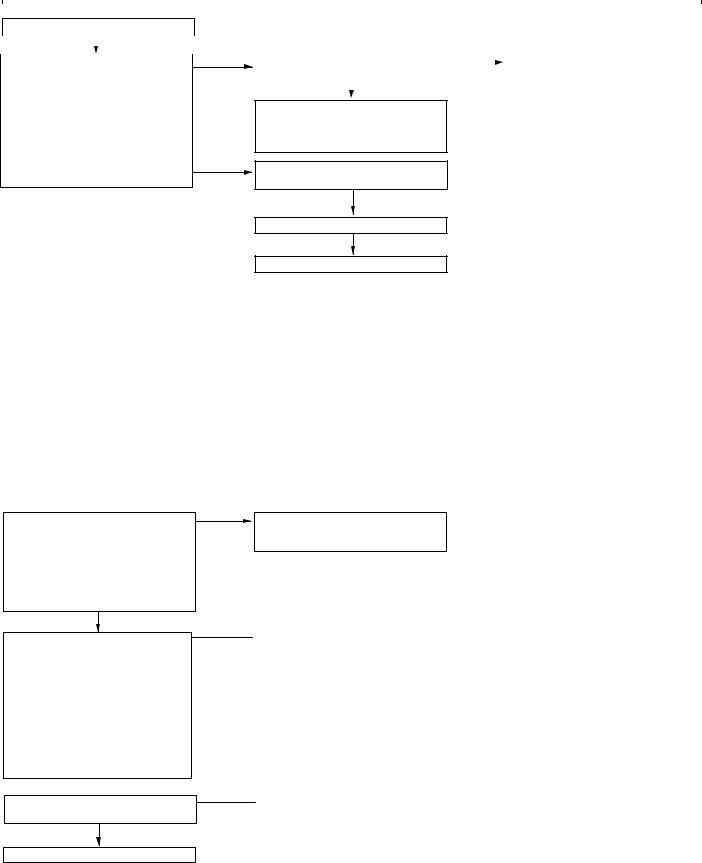
13D-20 |
MPI <4G63> ï Troubleshooting |
From the previous page
|
|
OK |
|
|
|
|
|
|
NG |
|
Measure at the engine-A/T-ECU |
|
||
|
|
|
||
|
connector C-126 |
|
|
|
DMeasure voltage at the engine-A/T-ECU terminal.
D Ignition switch: ON
DVoltage between terminal 78 and earth
OK: Accelerator pedal fully re-
leased: 0.335 ï 0.935 V Accelerator pedal fully de- OK pressed: 4.4 ï 5.3 V
|
|
NG |
||
Check the following connector: |
||||
|
Repair |
|||
|
||||
C-126 |
|
|||
|
|
|||
|
|
|
|
|
|
OK |
|
|
|
|
|
|
|
|
Check the harness wire between the throttle position sensor and the engine-A/T-ECU, and repair if necessary.
NG
Check the following connectors:  Repair
C-124, C-126
OK
Check the trouble symptoms.
NG
Replace the engine-A/T-ECU.
Code No. 21 Engine coolant temperature sensor system |
Probable cause |
|
|
Range of Check |
D Malfunction of the engine coolant temperature |
D 60 seconds after the ignition switch is set to the “ON” position, or after the |
sensor |
completion of start of engine. |
D Open or short circuit in the engine coolant |
Set Conditions |
temperature sensor circuit or loose connector |
D The sensor output voltage is 4.6 V or more for 4 seconds (equivalent to |
contact |
ï45_C or lower of engine coolant temperature) |
D Malfunction of the engine-A/T-ECU |
or |
|
D The sensor output voltage is 0.1 V or less for 4 seconds (equivalent to |
|
140_C or higher of engine coolant temperature) |
|
|
|
Range of Check |
|
D Engine: After starting |
|
Set Condition |
|
D The engine coolant temperature has reduced from over 40_C to less than |
|
40_C, and that condition has lasted for five minutes or more. |
|
|
|
M.U.T.-II/III Data list
21 Engine coolant temperature sensor
OK: When the engine is cold, the temperature is roughly the same as ambient temperature. If warm, it is 80 ï 120_C.
NG
Measure at engine coolant temperature sensor connector B-111.
D Disconnect the connector and measure at the sensor side.
DResistance between terminals 1 and 2
OK: At 20_C of engine coolant temperature: 2.1 ï 2.7 k: At 80_C of engine coolant temperature:
0.26ï 0.36 k:
 OK
OK
Check the following connector:
B-111
OK
To the next page
OK
Intermittent malfunction
(Refer to GROUP 00 ï Points to Note for Intermittent Malfunctions.)
NG
 Replace
NG
 Repair

|
|
|
|
|
|
MPI <4G63> ï Troubleshooting |
|
|
|
|
|
13D-21 |
||||||||||||||
|
|
|
|
|
|
|
|
|
|
|
|
|
|
|
|
|
|
|
|
|
|
|
||||
|
From the previous page |
|
|
|
|
|
|
|
|
|
|
|
|
|
|
|
|
|
|
|
|
|
||||
|
|
|
|
|
|
|
|
|
|
|
|
|
|
|
|
|
|
|
|
|
|
|
|
|
|
|
|
|
|
|
|
OK |
|
|
|
|
|
|
|
|
|
OK |
|
|
|
|
|
|
|
|
|
||
|
|
|
|
|
|
(1) NG |
|
|
|
|
|
|
|
|
|
|
|
|
|
|
|
|||||
|
Measure at engine coolant |
|
|
|
|
Measure at engine-A/T-ECU |
|
|
|
|
|
|
|
Check the following connector: |
|
|||||||||||
|
|
|
|
|
|
|
|
|
|
|
|
|||||||||||||||
|
|
|
|
|
|
|
|
|
|
|
|
C-124 |
|
|
|
|
||||||||||
|
temperature sensor connector B-111. |
|
|
|
|
connector C-124. |
|
|
|
|
|
|
|
|
|
|
|
|||||||||
|
|
|
|
|
|
|
|
|
|
|
|
|
|
|
|
|
|
|||||||||
|
D |
Disconnect the connector and |
|
|
|
|
D |
Measure the voltage at the |
|
|
|
|
|
|
|
|
OK |
NG |
||||||||
|
|
measure at the harness side. |
|
|
|
|
D |
|
engine-A/T-ECU terminal. |
|
|
|
|
|
|
|
|
|
|
Repair |
||||||
|
|
|
|
|
|
|
|
|
|
|
|
|
|
|
|
|
||||||||||
|
(1) Voltage between terminal 1 and |
|
|
|
|
|
Disconnect connector B-111. |
|
|
|
|
|
|
|
|
|
|
|
|
|
||||||
|
|
earth |
|
|
|
|
D |
|
Ignition switch: ON |
|
|
|
|
|
|
|
Check the harness wire between the |
|
||||||||
|
|
(Ignition switch: ON) |
|
|
|
|
D |
Voltage between terminal 44 and |
|
|
|
|
|
|
|
engine coolant temperature sensor |
|
|||||||||
|
|
OK: 4.5 ï 4.9 V |
|
|
|
|
|
|
earth |
|
|
|
|
|
|
|
and the engine-A/T-ECU, and repair |
|
||||||||
|
(2) Resistance between terminal 2 |
|
|
|
|
|
|
OK: 4.5 ï 4.9 V |
|
|
|
|
|
|
|
if necessary. |
|
|
|
|
||||||
|
|
and earth |
|
|
|
|
|
|
|
NG |
|
|
|
|
|
|
|
|
|
|
|
|
|
|||
|
|
OK: 2 : or less |
|
|
|
|
|
|
|
|
|
|
|
|
|
|
|
|
|
|
|
|
||||
|
|
|
|
|
|
|
|
|
|
|
|
|
|
|
|
|
|
|
|
|
|
|
||||
|
|
|
|
|
|
|
|
|
|
|
|
|
|
|
NG |
|
|
|
|
|
|
|
|
|
||
|
|
|
|
|
|
|
|
|
|
Check the following connector: |
|
|
|
|
Repair |
|
|
|
|
|||||||
|
|
|
|
|
|
|
|
|
|
|
|
|
|
|
|
|
|
|
|
|
||||||
|
|
|
|
|
|
|
|
|
|
C-124 |
|
|
|
|
|
|
|
|
|
|
|
|||||
|
|
|
|
|
|
|
|
|
|
|
|
|
|
|
|
|
|
|
|
|
|
|
||||
|
|
|
|
|
|
|
|
|
|
|
|
|
|
|
|
|
|
|
|
|
|
|
|
|
|
|
|
|
|
|
|
|
|
|
|
|
|
|
|
OK |
|
|
|
|
|
|
|
|
|
|
|
|
|
|
|
|
|
|
|
|
|
|
|
|
|
|
|
|
|
|
|
|
|
|
|
|
|
|||
|
|
|
|
|
|
|
|
|
|
Check the harness wire between the |
|
|
NG |
|
|
|
Repair |
|
|
|
|
|||||
|
|
|
|
|
|
|
|
|
|
engine coolant temperature sensor |
|
|
|
|
|
|
|
|
|
|
|
|||||
|
|
|
|
|
|
|
|
|
|
and the engine-A/T-ECU. |
|
|
|
|
|
|
|
|
|
|
|
|
|
|||
|
|
|
|
|
|
|
|
|
|
|
|
|
|
|
|
|
|
|
|
|
|
|
|
|
|
|
|
|
|
|
|
|
|
|
|
|
|
|
|
OK |
|
|
|
|
|
|
|
|
|
|
|
|
|
|
|
|
|
|
|
|
|
|
|
|
|
|
|
|
|
NG |
|
|
|
|
|
|
|
|
|
|
|
|
|
|
|
|
(2) NG |
|
|
Check the trouble symptoms. |
|
|
|
|
|
Replace the engine-A/T-ECU. |
|||||||||||
|
|
|
|
|
|
|
|
|
|
NG |
|
|
|
|||||||||||||
|
|
|
|
|
|
|
|
|
|
|
|
|
|
|
|
|
|
|
|
|
|
|||||
|
|
|
|
|
|
|
|
|
|
|
|
|
|
|
|
|
|
|
|
|
||||||
|
|
|
|
|
|
|
|
|
Check the following connector: |
|
|
|
|
|
|
|
Repair |
|
|
|
|
|||||
|
|
|
|
|
|
|
|
|
|
|
|
|
|
|
|
|
|
|
|
|||||||
|
|
|
|
|
|
|
|
|
C-124 |
|
|
|
|
|
|
|
|
|
|
|
||||||
|
|
|
|
|
|
|
|
|
|
|
|
|
|
|
|
|
|
|
|
|
|
|||||
|
|
|
|
|
|
|
|
|
|
|
|
|
|
|
|
|
|
|
|
|
|
|
|
|
|
|
|
|
|
|
|
|
|
|
|
|
|
|
|
OK |
|
|
|
|
|
|
|
|
|
|
|
|
|
|
|
|
|
|
|
|
|
|
|
|
|
|
|
|
|
|
|
|
|
|
|
|
|
|
||
|
|
|
|
|
|
|
|
|
|
Check the harness wire between the |
|
|
|
NG |
|
|
|
Repair |
|
|
|
|
||||
|
|
|
|
|
OK |
|
|
|
|
engine coolant temperature sensor |
|
|
|
|
|
|
|
|
|
|
|
|||||
|
|
|
|
|
|
|
|
|
|
and the engine-A/T-ECU. |
|
|
|
|
|
|
|
|
|
|
|
|
|
|||
|
|
|
|
|
|
|
|
|
|
|
|
|
OK |
|
|
|
|
|
|
|
|
|
|
|
|
|
|
|
|
|
|
|
|
|
|
|
|
|
|
|
|
|
|
NG |
|
|
|
|
|
|
|
|
|
|
|
|
|
|
|
|
|
|
|
Check the trouble symptoms. |
|
|
|
|
|
|
Replace the engine-A/T-ECU. |
|||||||||
|
|
|
|
|
|
|
|
|
|
|
|
|
|
|
|
|
||||||||||
|
|
|
|
|
|
|
|
|
|
|
|
|
|
|
||||||||||||
|
|
|
|
|
|
NG |
|
|
|
|
|
|
|
NG |
|
|
|
|
|
|
|
|
|
|||
|
Measure at engine coolant |
|
|
|
|
Check the engine coolant |
|
|
|
|
|
|
Repair |
|
|
|
|
|||||||||
|
|
|
|
|
|
|
|
|
|
|
|
|
|
|||||||||||||
|
temperature sensor connector B-111. |
|
|
|
|
temperature sensor. |
|
|
|
|
|
|
|
|
|
|
|
|||||||||
|
|
|
|
|
|
|
|
|
|
|
|
|
|
|
|
|||||||||||
|
|
|
|
|
|
|
|
|
|
|
|
|
|
|
|
|
|
|||||||||
|
D Use test harness (MB991658) to |
|
|
|
|
(Refer to P.13D-98.) |
|
|
|
|
|
|
|
|
|
|
|
|
|
|||||||
|
|
connect the connector, and |
|
|
|
|
|
|
|
OK |
|
|
|
|
|
|
|
|
|
|
|
|
|
|||
|
|
measure at the pick-up harness. |
|
|
|
|
|
|
|
|
|
|
|
|
|
|
|
|
|
|
|
|
||||
|
|
|
|
|
|
|
|
|
|
|
|
|
|
|
|
|
|
|
|
|
|
|
||||
|
D |
Ignition switch: ON |
|
|
|
|
Check the following connector: |
|
|
|
NG |
|
|
Repair |
|
|
|
|
||||||||
|
D |
Voltage between terminal 1 and |
|
|
|
|
C-124 |
|
|
|
|
|
|
|
|
|
|
|||||||||
|
|
|
|
|
|
|
|
|
|
|
|
|
|
|
|
|
|
|||||||||
|
|
earth |
|
|
|
|
|
|
|
|
|
|
|
|
|
|
|
|
|
|||||||
|
|
|
|
|
|
|
|
|
|
|
|
|
|
|
|
|
|
|
|
|
|
|
||||
|
|
|
|
|
|
|
|
|
OK |
|
|
|
|
|
|
|
|
|
|
|
|
|
||||
|
|
OK: At 0_C of engine coolant |
|
|
|
|
|
|
|
|
|
|
|
|
|
|
|
|
|
|
|
|
||||
|
|
|
|
|
|
|
|
|
|
|
|
|
|
|
|
|
|
|
|
|
|
|
||||
|
|
temperature: 3.2 ï 3.8 V |
|
|
|
|
|
|
|
|
|
|
|
|
|
|
|
|
|
|
|
|
|
|||
|
|
|
|
|
|
Check the harness wire between the |
|
|
|
|
|
|
|
|
|
|
|
|
|
|||||||
|
|
At 20_C of engine coolant |
|
|
|
|
|
|
|
|
|
|
|
|
|
|
|
|
|
|||||||
|
|
|
|
|
|
engine coolant temperature sensor |
|
|
|
|
|
|
|
|
|
|
|
|
|
|||||||
|
|
temperature: 2.3 ï 2.9 V |
|
|
|
|
|
|
|
|
|
|
|
|
|
|
|
|
|
|||||||
|
|
|
|
|
|
and the engine-A/T-ECU, and repair |
|
|
|
|
|
|
|
|
|
|
|
|
|
|||||||
|
|
At 40_C of engine coolant |
|
|
|
|
|
|
|
|
|
|
|
|
|
|
|
|
|
|||||||
|
|
|
|
|
|
if |
necessary. |
|
|
|
|
|
|
|
|
|
|
|
|
|
||||||
|
|
temperature: 1.3 ï 1.9 V |
|
|
|
|
|
|
|
|
|
|
|
|
|
|
|
|
|
|||||||
|
|
|
|
|
|
|
|
|
|
|
|
|
|
|
|
|
|
|
|
|
|
|
||||
|
|
|
|
|
|
|
|
|
|
|
|
|
|
|
|
|
|
|
|
|
|
|
||||
|
|
At 80_C of engine coolant |
|
|
|
|
|
|
|
|
|
|
|
|
|
|
|
|
|
|
|
|
|
|||
|
|
temperature: 0.3 ï 0.9 V |
|
|
|
|
|
|
|
|
|
|
|
|
|
|
|
|
|
|
|
|
|
|||
|
|
|
|
OK |
|
|
|
|
|
|
|
|
|
|
|
|
|
|
|
|
|
|
|
|
|
|
|
|
|
|
|
|
NG |
|
|
|
|
|
|
|
|
|
|
|
|
|
|
|
|
|
|||
|
Check the trouble symptoms. |
|
|
|
|
Replace the engine-A/T-ECU. |
|
|
|
|
|
|
|
|
|
|
|
|
|
|||||||

13D-22 |
MPI <4G63> ï Troubleshooting |
|
|
|
|
|||||||||||||||||
|
|
|
|
|
|
|
|
|
|
|
|
|
|
|
|
|
|
|
|
|||
|
Code No. 22 Crank angle sensor system |
|
Probable cause |
|
|
|
|
|||||||||||||||
|
|
|
|
|
|
|
|
|
|
|
|
|
|
|
|
|
|
|
|
|||
|
Range of Check |
|
|
|
|
|
|
|
D Malfunction of the crank angle sensor. |
|
||||||||||||
|
D |
Engine is cranking |
|
|
|
|
|
|
|
D Open or short circuit in the crank angle sensor |
|
|||||||||||
|
Set Condition |
|
|
|
|
|
|
|
|
circuit or loose connector contact. |
|
|
|
|
||||||||
|
D |
Sensor output voltage does not change for 4 seconds (no pulse signal input). |
|
D |
Malfunction of the engine-A/T-ECU |
|
||||||||||||||||
|
|
|
|
|
|
|
|
|
|
|
|
|
|
|
|
|
|
|
|
|
|
|
|
|
|
|
OK |
|
|
|
|
|
|
|
|
|
|
|
|
|
|
|
|
||
|
M.U.T.-II/III Data list |
|
|
|
Intermittent malfunction |
|
|
|
|
|
|
|
|
|
|
|
|
|||||
|
|
|
|
|
|
|
|
|
|
|
|
|
|
|
|
|||||||
|
22 Crank angle sensor |
|
|
|
(Refer to GROUP 00 ï Points to |
|
|
|
|
|
|
|
|
|
|
|
||||||
|
|
OK: Refer to P.13D-66, DATA |
|
|
|
Note for Intermittent Malfunctions.) |
|
|
|
|
|
|
|
|
|
|
|
|||||
|
|
LIST REFERENCE TABLE. |
|
|
|
|
|
|
|
|
|
|
|
|
|
|
|
|
|
|
|
|
|
|
|
|
|
|
|
|
|
|
|
|
|
|
|
|
|
|
|
|
|
||
|
|
|
|
|
|
|
|
|
|
|
|
|
|
|
|
|
|
|
|
|
|
|
|
|
|
NG |
|
|
|
|
|
|
|
|
|
|
|
|
|
|
|
|
|
|
|
|
|
|
|
NG |
|
|
|
|
|
|
|
|
|
|
|
|
|
|
|
|||
|
Check the following connector: |
|
|
|
Repair |
|
|
|
|
|
|
|
|
|
|
|
|
|||||
|
|
|
|
|
|
|
|
|
|
|
|
|
|
|
||||||||
|
B-116 |
|
|
|
|
|
|
|
|
|
|
|
|
|
|
|
|
|
|
|
||
|
|
|
|
|
|
|
|
|
|
|
|
|
|
|
|
|
|
|
|
|
|
|
|
|
|
OK |
|
|
|
|
|
|
|
|
|
|
|
|
|
|
|
|
|
|
|
|
|
|
|
(1) NG |
|
|
|
|
|
|
|
|
|
|
|
|
|
|
|
|
|
|
|
Measure at the crank angle sensor |
|
|
|
Check the harness between the |
|
|
|
|
|
|
|
|
|
|
|
|
|||||
|
|
|
|
|
|
|
|
|
|
|
|
|
|
|
||||||||
|
connector B-116. |
|
|
|
crank angle sensor and earth, and |
|
|
|
|
|
|
|
|
|
|
|
||||||
|
D |
Disconnect the connector and |
|
|
|
repair if necessary. |
|
|
|
|
|
|
|
|
|
|
|
|
||||
|
|
measure at the harness side. |
|
|
|
|
|
|
|
|
|
|
|
|
|
|
|
|
|
|
|
|
|
|
|
|
|
|
|
|
|
|
|
|
|
|
|
|
|
|
|
|
|
||
|
(1) The resistance between terminal |
(2) NG |
|
|
|
|
|
|
|
OK |
|
|
|
|
|
|||||||
|
|
1 and earth |
|
|
|
Measure at the engine-A/T-ECU |
|
|
|
|
|
Check the following connector: |
|
|
||||||||
|
|
|
|
|
|
|
|
|
|
|||||||||||||
|
|
OK: 2 : or less |
|
|
|
connector C-124. |
|
|
|
|
|
C-124 |
|
|
|
|
||||||
|
(2) The voltage between terminal 2 |
|
|
|
D |
Measure the voltage at the |
|
|
|
|
|
|
OK |
|
NG |
|||||||
|
|
and earth |
|
|
|
|
engine-A/T-ECU terminal. |
|
|
|
|
|
|
|
||||||||
|
|
|
|
|
|
|
|
|
|
|
|
|
|
|
Repair |
|||||||
|
|
(Ignition switch: ON) |
|
|
|
D |
Disconnect the connector B-116 |
|
|
|
|
|
|
|
|
|||||||
|
|
|
|
|
|
|
|
|
|
|
|
|
|
|
|
|||||||
|
|
OK: 4.9 ï 5.1 V |
|
|
|
D |
Ignition switch: ON |
|
|
|
|
|
|
|
|
|
|
|
|
|||
|
|
|
|
|
|
|
|
|
|
Check the harness wire between the |
|
|
||||||||||
|
(3) The voltage between terminal 3 |
|
|
|
D |
The voltage between terminal 45 |
|
|
|
|
|
|
||||||||||
|
|
|
|
|
|
|
|
crank angle sensor and the |
|
|
||||||||||||
|
|
and earth |
|
|
|
|
and earth |
|
|
|
|
|
|
|
||||||||
|
|
|
|
|
|
|
|
|
|
|
engine-A/T-ECU, and repair if |
|
|
|||||||||
|
|
(Ignition switch: ON) |
|
|
|
|
OK: 4.9 ï 5.1 V |
|
|
|
|
|
|
|
||||||||
|
|
|
|
|
|
|
|
|
|
|
necessary. |
|
|
|
|
|||||||
|
|
OK: System voltage |
|
|
|
|
|
NG |
|
|
|
|
|
|
|
|
|
|
|
|
||
|
|
|
|
|
|
|
|
|
|
|
|
|
|
|
|
|
|
|
|
|
||
|
|
|
|
|
|
|
|
|
|
|
|
|
|
NG |
|
|
|
|
||||
|
|
|
|
|
|
|
Check the following connector: |
|
|
|
|
Repair |
|
|
|
|
||||||
|
|
|
|
|
|
|
|
|
|
|
|
|
|
|
||||||||
|
|
|
|
|
|
|
C-124 |
|
|
|
|
|
|
|
|
|
|
|
|
|||
|
|
|
|
|
|
|
|
|
|
|
|
|
|
|
|
|
|
|
|
|
|
|
|
|
|
|
|
|
|
|
|
OK |
|
|
|
|
|
|
|
|
|
|
|
|
|
|
|
|
|
|
|
|
|
|
|
|
|
|
|
NG |
|
|
|
|
||||
|
|
|
|
|
|
|
Check the harness wire between the |
|
|
|
|
Repair |
|
|
|
|
||||||
|
|
|
|
|
|
|
|
|
|
|
|
|
|
|
||||||||
|
|
|
|
|
|
|
|
|
|
|
|
|
|
|
|
|
|
|||||
|
|
|
|
|
|
|
crank angle sensor and the |
|
|
|
|
|
|
|
|
|
|
|
|
|||
|
|
|
|
|
|
|
engine-A/T-ECU. |
|
|
|
|
|
|
|
|
|
|
|
|
|||
|
|
|
|
|
|
|
|
|
|
|
|
|
|
|
|
|
|
|
|
|
|
|
|
|
|
|
|
|
|
|
|
OK |
|
|
|
|
|
|
|
|
|
|
|
|
|
|
|
|
|
|
|
|
|
|
|
|
|
|
|
NG |
|
|
|
|
|
|
|
|
|
|
|
|
|
|
|
Check the trouble symptoms. |
|
|
|
|
|
Replace the engine-A/T-ECU. |
|
|
|||||||
|
|
|
|
|
|
|
|
|
|
|
|
|
|
|
|
|
|
|
|
|
|
|
|
|
|
|
(3) NG |
|
|
|
|
|
|
|
|
NG |
|
|
|
|
|||||
|
|
|
|
|
|
|
Check the following connector: |
|
|
|
|
Repair |
|
|
|
|
||||||
|
|
|
|
|
|
|
|
|
|
|
|
|
|
|
||||||||
|
|
|
|
|
|
|
B-16X |
|
|
|
|
|
|
|
|
|
|
|
|
|||
|
|
|
|
|
|
|
|
|
|
|
|
|
|
|
|
|
|
|
|
|
|
|
|
|
|
|
|
|
|
|
|
OK |
|
|
|
|
|
|
|
|
|
|
|
|
|
|
|
|
|
|
|
|
|
|
|
|
|
|
|
|
|
|
|
|
||||
|
|
|
|
|
|
|
Check the harness wire between the |
|
|
|
|
|
|
|
|
|
||||||
|
|
|
OK |
|
|
|
|
|
|
|
|
|
|
|
|
|||||||
|
|
|
|
|
|
crank angle sensor and the engine |
|
|
|
|
|
|
|
|
|
|
|
|||||
|
|
|
|
|
|
|
control relay, and repair if necessary. |
|
|
|
|
|
|
|
|
|
||||||
|
To the next page |
|
|
|
|
|
|
|
|
|
|
|
|
|
|
|
|
|
|
|
||
|
|
|
|
|
|
|
|
|
|
|
|
|
|
|
|
|
|
|
|
|
|
|

|
|
|
|
|
MPI <4G63> ï Troubleshooting |
13D-23 |
||||||||
|
|
|
|
|
|
|
|
|
|
|
|
|||
From the previous page |
|
|
|
|
|
|
|
|
|
|
|
|
||
|
|
|
|
|
|
|
|
|
|
|
|
|
|
|
|
|
OK |
|
|
|
|
|
|
|
|
|
|
||
|
|
|
|
NG |
|
|
|
|
|
|
|
NG |
Replace |
|
|
|
|
|
|
|
|
|
|
||||||
Use an analyzer to measure the |
|
|
|
Check the crank angle sensor vane. |
|
|
|
|||||||
|
|
|
|
|
|
|||||||||
|
|
|
|
|
||||||||||
output waveform at the crank angle |
|
|
|
|
|
|
|
|
|
|
|
|
||
|
|
|
|
|
OK |
|
||||||||
sensor connector B-116. |
|
|
|
|
|
|
||||||||
|
|
|
|
|
|
|
|
|
|
|
|
|||
D |
Use the test harness |
|
|
|
|
|
|
|
|
|
|
|
|
|
|
|
Replace the crank angle sensor. |
|
|
|
|
|
|||||||
|
(MD998478) to connect the |
|
|
|
|
|
|
|
||||||
|
|
|
|
|
|
|
|
|
|
|
|
|
||
|
connector, and measure at the |
|
|
|
|
|
|
|
|
|
|
|
|
|
|
pick-up harness side. |
|
|
|
|
|
|
|
|
|
|
|
|
|
D |
|
|
Check the trouble symptoms. |
|
|
|
|
|
||||||
Engine: Idling |
|
|
|
|
|
|
|
|||||||
|
|
|
|
|
|
|
|
|
|
|
|
|||
D The voltage between terminal 2 |
|
|
|
|
|
NG |
|
|||||||
|
and earth |
|
|
|
|
|
|
|
|
|
NG |
Repair |
||
|
|
|
Check the following connectors: |
|
||||||||||
|
OK: A normal waveform should |
|
|
|
|
|
|
|
||||||
|
|
|
|
|
|
|
|
|||||||
|
|
|
|
|
B-16X, C-124 |
|
|
|
|
|||||
|
be displayed as described |
|
|
|
|
|
|
|
||||||
|
|
|
|
|
|
|
|
|
|
|
|
|
||
|
on P.13D-81 (Inspection |
|
|
|
|
|
OK |
|
||||||
|
Procedure Using an Ana- |
|
|
|
|
|
|
|||||||
|
|
|
|
|
|
|
|
|
|
|
|
|
||
|
lyzer). Its maximum value |
|
|
|
|
Check the harness wires between |
|
|
|
|||||
|
should be 4.8 V or more, |
|
|
|
|
the crank angle sensor and the |
|
|
|
|||||
|
and its minimum value |
|
|
|
|
engine-A/T-ECU, crank angle sensor |
|
|
|
|||||
|
should be 0.6 V or less |
|
|
|
|
and the engine control relay, and the |
|
|
|
|||||
|
with no noise in waveform. |
|
|
|
|
crank angle sensor and earth. Then, |
|
|
|
|||||
|
|
OK |
|
|
repair if necessary. |
|
|
|
||||||
|
|
|
|
|
|
|
|
|
|
|
|
|||
|
|
|
|
|
|
|
|
|
|
|
|
|
|
|
Check the trouble symptoms.
NG
Replace the engine-A/T-ECU.

13D-24 |
MPI <4G63> ï Troubleshooting |
|
|
|
|
Code No. 23 Camshaft position sensor system |
Probable cause |
|
|
|
|
Range of Check |
|
D Malfunction of the camshaft position sensor |
D During engine cranking and driving |
|
D Open or short circuit in the camshaft position |
Set Condition |
|
sensor circuit or loose connector contact. |
D The sensor output voltage does not change for 4 seconds (no pulse signal |
D Malfunction of the engine-A/T-ECU |
|
input). |
|
|
|
|
|
Check the following connector:
B-107
OK
Measure at camshaft position sensor connector B-107.
DDisconnect the connector and measure at the harness side.
(1)The voltage between terminal 3 and earth
(Ignition switch: ON) OK: System voltage
(2)The voltage between terminal 2 and earth
(Ignition switch: ON) OK: 4.9 ï 5.1 V
(3)The resistance between terminal 1 and earth
OK: 2 : or less
OK
NG
|
|
|
Repair |
NG |
|||
(1) NG |
|||||||
|
|||||||
|
|
|
Check the following connector: |
|
Repair |
||
|
|
||||||
|
|
|
B-16X |
|
|
||
|
|
|
|
|
|
|
|
|
|
|
|
OK |
|
|
|
|
|
|
|
|
|
|
|
Check the harness wire between the camshaft position sensor connector and the engine control relay, and repair if necessary.
(2) NG
Measure at the engine-A/T-ECU connector C-124.
DMeasure the voltage at the engine-A/T-ECU terminal.
D Disconnect connector B-107.
D Ignition switch: ON
DThe voltage between terminal 56
and earth
OK: 4.9 ï 5.1 V
NG
Check the following connector:
C-124
OK
Check the harness wire between the intermediate connector and the engine-A/T-ECU.
OK
Check the trouble symptoms.
(3) NG
 Check the harness wire between the camshaft position sensor connector and earth, and repair if necessary.
OK |
|
Check the following connector: |
|
|
C-124 |
|
|
|
|
|
|
|
|
|
|
|
|
OK |
NG |
 Repair
Check the harness wire between the camshaft position sensor connector and the engine-A/T-ECU, and repair if necessary.
NG
 Repair
NG
 Repair
NG
Replace the engine-A/T-ECU.
NG
Use an analyzer to measure the output waveform at camshaft position sensor connector B-107.
DUse test harness (MB991709) to connect the connector, and
measure at the pick-up harness. D Engine: Idling
DThe voltage between terminal 2 and earth
OK: A normal waveform should be displayed as described on P.13D-81 (Inspection Procedure Using an Analyzer), its maximum value should be 4.8 V or more, and its minimum value should be 0.6 V or less with no noise in waveform.
OK
OK
Check the trouble symptoms.
NG
Replace the engine-A/T-ECU.
NG
Check the camshaft position sensing  Replace cylinder.
OK
Replace the camshaft position sensor.
Check the trouble symptoms. |
|
|
|
|
|
|
|
|
NG |
|
|
|
|
NG |
|
|
|
||
Check the following connectors: |
|
Repair |
|
B-16X, C-124 |
|
|
|
|
|
|
|
|
OK |
|
|
Check the harness wires between the camshaft position sensor connector and the engine-A/T-ECU, the camshaft position sensor connector and the engine control relay, and the camshaft position sensor connector and earth. Then, repair if necessary.
 Intermittent malfunction
(Refer to GROUP 00 ï Points to Note for Intermittent Malfunctions.)

|
MPI <4G63> ï Troubleshooting |
13D-25 |
|||||||
|
|
|
|
|
|
|
|
|
|
Code No. 24 Vehicle speed signal system |
|
|
|
|
Probable cause |
|
|
||
|
|
|
|
|
|
|
|
||
Range of Check |
|
|
|
|
D Malfunction of the output shaft speed sensor |
||||
D 60 seconds after the ignition switch is set to the “ON” position, or after the |
D |
Open or short circuit in the output shaft speed |
|||||||
completion of start of engine. |
|
|
|
|
|
sensor circuit or loose connector contact |
|||
D The engine speed is more than 2,300 r/min. |
|
|
|
|
D |
Malfunction of the engine-A/T-ECU |
|
|
|
D Volumetric efficiency 50 % or more |
|
|
|
|
|
|
|
|
|
Set Condition |
|
|
|
|
|
|
|
|
|
D The vehicle speed signal does not change for 4 seconds (no pulse signal |
|
|
|
|
|
||||
input.) |
|
|
|
|
|
|
|
|
|
|
|
|
|
|
|
|
|
|
|
|
|
YES |
|
|
|
|
|
|
|
M.U.T.-II/III Self-Diag code |
|
|
D |
Automatic transmission system check |
|
|
|||
|
|
|
|
||||||
D Is diagnosis code of automatic transmission system output? |
|
|
|
(Refer to GROUP 23B ï Troubleshooting ï Inspection |
|
||||
|
|
|
|
|
chart for diagnosis codes) |
|
|
||
|
NO |
OK |
|
|
|
||||
|
|
|
|
|
|
|
|||
|
|
|
|
|
|
|
|||
|
|
|
|
|
|
|
|
||
|
|
|
|
|
|
|
|||
Check the trouble symptoms. |
|
|
Intermittent malfunction. (Refer to GROUP 00 ï Points to Note |
|
|||||
|
|
||||||||
|
|
|
|
for |
Intermittent Malfunctions.) |
|
|
||
|
NG |
|
|
|
|
||||
|
|
|
|
|
|
|
|
|
|
|
|
|
|
|
|
|
|
|
|
|
|
|
|
|
|
|
|
|
|
|
|
|
|
|
|
|
|
|
|
Replace the engine-A/T-ECU. |
|
|
|
|
|
|
|
|
|
|
|
|
|
|
|
|
|
|
|
 Loading...